1
1
7
2
3
6
4
5
26
10
8
SUPPLY PORT
3/8” P.T.
9
12 & 13
25
27
11
14
SECTION VIEW OF SUPPLY PORT
15
16
23
24
22
21
20
18
17
19
Key No.
1
Description
Screw
Key No.
10
Description
Retaining Ring
Key No.
19
Description
Cover
2
3
Cover
Exhaust Diaphragm
11
12
O-Ring Retainer
O-Ring
20
21
Shims
Inner Spring
4
5
Cap Screw
Lock Washer
13
14
O-Ring
Spring
22
23
Outer Spring
Balance Piston
6
7
Cover
Control Piston
15
16
Spring Seat
Valve Body
24
25
O-Ring
Retaining Ring
8
9
Retaining Ring
Inlet/Exhaust Assy.
17
18
Cap Screws
Lockwashers
26
27
Supply Adapter
O-Ring
FIGURE 2
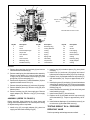
4. Remove large retaining ring from body (8) and remove
inlet/exhaust valve assembly (9).
5. Remove retaining ring from inlet/exhaust valve assembly.
Remove o-ring retainer (11), remove inner and outer
o-rings (12 & 13) from retainer. Remove spring (14) and
spring seat (15) from valve body (16).
6. Remove four cap screws (17) with lockwashers (18) from
opposite end and remove cover (19).
7. Remove shims (20) and inner (21) and outer (22) springs.
8. Remove balance piston (23). Remove o-ring (24) from
balance piston.
9. Remove retaining ring (25) from supply port. Remove
supply adapter (26). Remove o-ring (27) from supply
adapter.
ASSEMBLY (REFER TO FIGURE 2)
Before assembly, lightly lubricate all o-rings, bores and
mating surfaces with (Bendix Pc. No. 291126) Dow Coming
55-M pneumatic grease or equivalent.
1. Install o-ring (27) on supply adapter (26), place into
supply port and install retaining ring (25).
2. Install o-ring (24) on balance piston (23), place piston
into body.
3. Install inner (21) and outer (22) springs into base of
balance piston and place shims (20) on top of springs.
4. Replace cover (19) and attach with four cap screws (17)
with lockwashers (18). Torque to approximately 45 in.
lbs.
5. Install spring seat (15) and spring (14) onto inlet/exhaust
valve body (9). Install o-rings (12 & 13) onto o-ring retainer
(11) and place on top of spring (14), compress and install
retaining ring (10).
6. Install inlet/exhaust assembly (9) into valve body and
install retaining ring (8).
7. Install control piston (7) into valve body.
8. Replace cover (6) and attach with four cap screws (4)
and lockwashers (5). Torque to approximately 100 in.
lbs.
9. Install exhaust diaphragm (3) and exhaust cover (2) on
to valve cover (6) and attach with screw (1).
TESTING REBUILT RV-4™ PRESSURE
REDUCING VALVE
Perform operating and leakage tests as outlined.
3