1
6. Devices with stripped threads or damaged parts should
be replaced. Repairs requiring machining should not be
attempted.
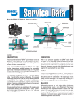
REMOVING THE QR-N™ VALVE
ASSEMBLY
1. Place the supply port of the upper body down on a clean,
level work surface. Install the flat circular diaphragm in
the upper body making certain it is CENTERED.
1. Park the vehicle on a level surface. Block the wheels
and/or hold the vehicle by means other than the air
brakes.
2. If applicable, install and center the diaphragm follower
with its flat flange side against the diaphragm. Install
the spring on the diaphragm follower.
2. Drain all air brake system reservoirs.
3. Install the sealing ring on the lower body and carefully
install the lower body on the upper body. Make certain
that the diaphragm remains centered in the upper body
and the sealing ring enters its groove in the upper body.
3. Identify, mark and disconnect all air lines from the valve.
4. Remove all tubing or hose fittings from the valve.
5. Remove the valve mounting hardware and the valve.
DISASSEMBLY
The following disassembly procedure is provided as a
reference. Before disassembling the QR-N™ valve, a Bendix
maintenance kit or genuine replacement parts should be
available.
1. Remove the four 1/4" flange nuts and bolts that secure
the upper and lower body halves. NOTE: Before removing
the last two nuts and bolts completely, check the opening
between the body halves to determine if the QR-N™ valve
has a differential spring installed. If so, a light spring
load should be anticipated and can be easily controlled
by manually holding the body halves together.
2. Separate the body halves and remove the diaphragm
(and diaphragm follower and spring if so equipped).
3. Remove the sealing ring between the body halves.
4. Install the four 1/4" flange nuts and bolts and torque to
60 inch pounds (6.78 N.M).
INSTALLING THE QR-N™ VALVE
1. Mount the QR-N™ valve on the vehicle.
2. Install the tubing or hose fittings in the upper body of the
QR-N™ valve. If a thread sealant is used, make certain
that this material will not enter the valve during use.
IMPORTANT: WHEN INSTALLING FITTINGS, DO NOT
TORQUE BEYOND;
12 ft. lbs. (16.3 N.M) for the supply port
10 ft. lbs. (13.6 N.M) for the delivery ports
OR DAMAGE TO THE UPPER BODY MAY RESULT.
3. Connect the air lines to the QR-N™ valve as identified in
Step 4 of the “Removal”.
4. Perform the “Operating and Leakage Tests” before placing
the vehicle in service.
CLEANING & INSPECTION
1. Clean the upper and lower body halves; also diaphragm
follower and spring (if applicable) in mineral spirits. Do
not immerse nonmetallic components for a prolonged
period of time (no more than 10 minutes). Dry all parts
thoroughly.
2. It is recommended that the diaphragm and sealing ring
be replaced after disassembly.
3. Inspect the upper body for galled threads and cracks. If
found, the entire QR-N™ valve should be replaced.
4. Inspect the interior valve portion of the lower body for
heavy corrosion and pitting. If found, replace the entire
QR-N™ valve assembly.
5. If applicable, inspect the diaphragm follower and spring
(if applicable) for any corrosion and pitting, replace if
necessary.
3