1
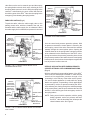
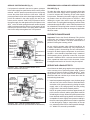
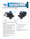
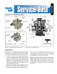
SERVICE SYSTEM FAILURE (Fig. 5)
EMERGENCY APPLICATION WITH SERVICE SYSTEM
If air pressure is reduced in the service system, pressure
in the trailer supply line (and likewise in the tractor) will be
reduced, until the pressure protection piston and spring
moves the piston and closes the inlet valve. With the
pressure protection inlet valve closed approximately 50-60
psi will be retained in the trailer supply line and in the
tractor service reservoir. With 50-60 psi pressure held in
the trailer supply line and against the control piston in the
SR-2™ valve, the trailer spring brakes will remain released
while low pressure warning will occur in the tractor (60 psi
minimum) to warn the driver. The spring brake reservoir
check valve will protect against loss of air pressure.
FAILURE (Fig. 6)
To brake the trailer after the service system failure has
occurred, the trailer supply valve or parking control valve
is used to exhaust the remaining 55 psi trailer supply
line pressure. Exhausting the trailer supply line removes
air pressure from the control piston of the SR-2™ valve
allowing the control inlet valve to seat and opening the
exhaust valve. The spring brake emergency section is then
exhausted through the SR-2™ valve. Sufficient pressure will
be maintained in the spring brake reservoir to release the
spring brake at least once after an emergency application
has been made.
PREVENTIVE MAINTENANCE
SERVICE
RESERVOIR
CHECK VALVE
PRESS.
PROTECTION
VALVE
PRESS.
PROTECTION
INLET VALVE
CONTROL
PISTON
SPRING BRAKE
RESERVOIR
CHECK VALVE
SPRING
BRAKE
RESERVOIR
SERVICE
RESERVOIR
TRAILER SUPPLY
LINE
TRAILER SERVICE
LINE
CONTROL INLET &
EXHAUST VALVE
SPRING BRAKE
RELAY VALVE OR
MODULATOR
Important: Review the Bendix Warranty Policy before
performing any intrusive maintenance procedures. A
warranty may be voided if intrusive maintenance is
performed during the warranty period.
No two vehicles operate under identical conditions, as
a result, maintenance intervals may vary. Experience is
a valuable guide in determining the best maintenance
interval for air brake system components. At a minimum,
the SR-2™ valve should be inspected every 6 months or
1500 operating hours, whichever comes first, for proper
operation. Should the SR-2™ valve not meet the elements
of the operational tests noted in this document, further
investigation and service of the valve may be required.
SERVICE AND LEAKAGE TESTS
FIGURE 5 - SR-2™ TRAILER SPRING BRAKE VALVE
SERVICE RESERVOIR FAILURE
SERVICE
RESERVOIR
CHECK VALVE
PRESS.
PROTECTION
VALVE
PRESS.
PROTECTION
INLET VALVE
CONTROL
PISTON
SPRING BRAKE
RESERVOIR
CHECK VALVE
SPRING
BRAKE
RESERVOIR
SERVICE
RESERVOIR
TRAILER SUPPLY
LINE
CONTROL INLET &
EXHAUST VALVE
SPRING BRAKE
TRAILER SERVICE
LINE
RELAY VALVE OR
MODULATOR
FIGURE 6 - SR-2™ TRAILER SPRING BRAKE VALVE
SPRING BRAKES APPLIED (FAILED SERVICE RESERVOIR)
Check the tractor dash gauge against a test gauge known
to be accurate prior to performing these tests. Connect
the tractor air lines to the trailer on which the SR-2™ trailer
spring brake valve is to be tested. Block all wheels or
otherwise hold both vehicles by a means other than air
brakes during these tests.
1. Install two separate test gauges or one dual test gauge
with one line to the service reservoir. Build the tractor
and trailer to full system pressure by placing the trailer
supply valve in the charge position and the parking
control valve in the brakes released position.
NOTE: As system pressure reaches approximately 55
psi, the service reservoir and the spring brake reservoir
should begin to charge. When full system pressure has
been obtained and the spring brakes are released, it is
acceptable to have a slightly lower pressure reading in
the service and spring brake reservoir than is registered
on the dash gauge. Apply a soap solution to the cap
nut, exhaust port and vent to detect possible leakage.
A 1” bubble in 5 seconds is permissible.
3