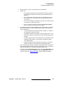
1
cpk=pÉêáÉë
rëÉêÛë=dìáÇÉ
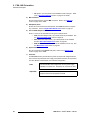
•
•
Manual #: 26-0702000-00
Revision: 01
cpk=pÉêáÉë==√==rëÉêÛë=dìáÇÉ
`çéóêáÖÜí
© Barco. March 31, 2010
All rights reserved. No part of this document may be copied, reproduced or translated. It
shall not otherwise be recorded, transmitted or stored in a retrieval system without the prior
written consent of Barco.
kçíáÅÉ
Barco provides this manual “as is” without warranty of any kind, either expressed or
implied, including but not limited to the implied warranties or merchantability and fitness for
a particular purpose. Barco may make improvements and/or changes to the product(s) and/
or the program(s) described in this publication at any time without notice.
This publication could contain technical inaccuracies or typographical errors. Changes are
periodically made to the information in this publication; these changes are incorporated in
new editions of this publication.
cÉÇÉê~ä=`çããìåáÅ~íáçåë=`çããáëëáçå=Ec``F=pí~íÉãÉåí
This equipment has been tested and found to comply with the limits for a class A digital
device, pursuant to Part 15 of the FCC rules. These limits are designed to provide
reasonable protection against harmful interference when the equipment is operated in a
commercial environment. This equipment generates, uses, and can radiate radio frequency
energy and, if not installed and used in accordance with the instruction manual, may cause
harmful interference to radio communications. Operation of this equipment in a residential
area may cause harmful interference, in which case the user will be responsible for
correcting any interference.
dì~ê~åíÉÉ=~åÇ=`çãéÉåë~íáçå
Barco provides a guarantee relating to perfect manufacturing as part of the legally
stipulated terms of guarantee. On receipt, the purchaser must immediately inspect all
delivered goods for damage incurred during transport, as well as for material and
manufacturing faults Barco must be informed immediately in writing of any complaints.
The period of guarantee begins on the date of transfer of risks, in the case of special
systems and software on the date of commissioning, at latest 30 days after the transfer of
risks. In the event of justified notice of compliant, Barco can repair the fault or provide a
replacement at its own discretion within an appropriate period. If this measure proves to be
impossible or unsuccessful, the purchaser can demand a reduction in the purchase price or
cancellation of the contract. All other claims, in particular those relating to compensation for
direct or indirect damage, and also damage attributed to the operation of software as well
as to other services provided by Barco, being a component of the system or independent
service, will be deemed invalid provided the damage is not proven to be attributed to the
absence of properties guaranteed in writing or due to the intent or gross negligence or part
of Barco.
If the purchaser or a third party carries out modifications or repairs on goods delivered by
Barco, or if the goods are handled incorrectly, in particular if the systems are commissioned
operated incorrectly or if, after the transfer of risks, the goods are subject to influences not
2
FSN Series • User’s Guide • Rev 01
agreed upon in the contract, all guarantee claims of the purchaser will be rendered invalid.
Not included in the guarantee coverage are system failures which are attributed to
programs or special electronic circuitry provided by the purchaser, e.g. interfaces. Normal
wear as well as normal maintenance are not subject to the guarantee provided by Barco
either.
The environmental conditions as well as the servicing and maintenance regulations
specified in this manual must be complied with by the customer.
qê~ÇÉã~êâë
Brand and product names mentioned in this manual may be trademarks, registered
trademarks or copyrights of their respective holders. All brand and product names
mentioned in this manual serve as comments or examples and are not to be understood as
advertising for the products or their manufactures.
`çãé~åó=^ÇÇêÉëë
Barco, Inc.
11101 Trade Center Drive
Rancho Cordova, California 95670
USA
•
•
•
Phone: (916) 859-2500
Fax: (916) 859-2515
Website: www.barco.com
Barco N.V.
Noordlaan 5
8520 Kuurne
BELGIUM
•
•
Phone: +32 56.36.82.11
Fax: +32 56.35.16.51
Technical Support
•
•
•
Customer Service Portal — www.barco.com/esupport
(866) 374-7878 — Events (24/7)
(866) 469-8036 — Digital Cinema (24/7)
FSN Series • User’s Guide • Rev 01
3
léÉê~íçêë=p~ÑÉíó=pìãã~êó
The general safety information in this summary is for operating personnel.
aç=kçí=oÉãçîÉ=`çîÉêë=çê=m~åÉäë
There are no user-serviceable parts within the unit. Removal of the top cover will expose
dangerous voltages. To avoid personal injury, do not remove the top cover. Do not operate
the unit without the cover installed.
mçïÉê=pçìêÅÉ
This product is intended to operate from a power source that will not apply more than 230
volts rms between the supply conductors or between both supply conductor and ground. A
protective ground connection by way of grounding conductor in the power cord is essential
for safe operation.
dêçìåÇáåÖ=íÜÉ=mêçÇìÅí
This product is grounded through the grounding conductor of the power cord. To avoid
electrical shock, plug the power cord into a properly wired receptacle before connecting to
the product input or output terminals. A protective-ground connection by way of the
grounding conductor in the power cord is essential for safe operation.
rëÉ=íÜÉ=mêçéÉê=mçïÉê=`çêÇ
Use only the power cord and connector specified for your product. Use only a power cord
that is in good condition. Refer cord and connector changes to qualified service personnel.
rëÉ=íÜÉ=mêçéÉê=cìëÉ
To avoid fire hazard, use only the fuse having identical type, voltage rating, and current
rating characteristics. Refer fuse replacement to qualified service personnel.
aç=kçí=léÉê~íÉ=áå=bñéäçëáîÉ=^íãçëéÜÉêÉë
To avoid explosion, do not operate this product in an explosive atmosphere.
4
FSN Series • User’s Guide • Rev 01
qÉêãë=få=qÜáë=j~åì~ä=~åÇ=bèìáéãÉåí=j~êâáåÖ=
t^okfkd
Highlights an operating procedure, practice, condition, statement, etc., which, if not strictly
observed, could result in injury to or death of personnel.
Note
Highlights an essential operating procedure, condition or
statement.
`^rqflk
The exclamation point within an equilateral triangle is intended to alert the user to the
presence of important operating and maintenance (servicing) instructions in the literature
accompanying the appliance.
^sboqfppbjbkq>
Le point d´exclamation dans un triangle equilatéral signale à alerter l´utilisateur qu´il y a
des instructions d´operation et d´entretien tres importantes dans la litérature qui
accompagne l´appareil.
slopf`eq
Ein Ausrufungszeichen innerhalb eines gleichwinkeligen Dreiecks dient dazu, den
Benutzer auf wichtige Bedienungs-und Wartungsanweisungen in der Dem Great
beiliegenden Literatur aufmerksam zu machen.
FSN Series • User’s Guide • Rev 01
5
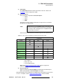
`Ü~åÖÉ=eáëíçêó
The table below lists the changes to the FSN Series User’s Guide.
Table 0-1. Change History
Rev
6
Date
ECP #
Description
Approved By
00
3/24/09
567874
FSN Series User’s Guide
R. Pellicano
01
3/31/10
577427
FSN Series User’s Guide revisions:
• New feature summary, explanations, links (Ch. 1)
• New DVE chapter
R. Pellicano
FSN Series • User’s Guide • Rev 01
q~ÄäÉ=çÑ=`çåíÉåíë
`Ü~éíÉê=N
fåíêçÇìÅíáçå =K=K=K=K=K=K=K=K=K=K=K=K=K=K=K=K=K=K=K=K=K=K=K=K=K=K=K=K=K=K=K=K=K=K=K=K=K=K=K=K=K=NT
In This Chapter . . . . . . . . . . . . . . . . . . . . . . . . . . . . . . . . . . . . . . . . . . . . . . . .
Software Version . . . . . . . . . . . . . . . . . . . . . . . . . . . . . . . . . . . . . . . . . . . . . .
Chapter Structure . . . . . . . . . . . . . . . . . . . . . . . . . . . . . . . . . . . . . . . . . . . . . .
How to Use This Guide. . . . . . . . . . . . . . . . . . . . . . . . . . . . . . . . . . . . . . . . . .
Navigating . . . . . . . . . . . . . . . . . . . . . . . . . . . . . . . . . . . . . . . . . . . . . .
Table of Contents and Index . . . . . . . . . . . . . . . . . . . . . . . . . . . . . . . .
Conventions . . . . . . . . . . . . . . . . . . . . . . . . . . . . . . . . . . . . . . . . . . . . . . . . . .
Glossary of Switcher Terms . . . . . . . . . . . . . . . . . . . . . . . . . . . . . . . . . . . . . .
About the FSN Series. . . . . . . . . . . . . . . . . . . . . . . . . . . . . . . . . . . . . . . . . . .
Overview . . . . . . . . . . . . . . . . . . . . . . . . . . . . . . . . . . . . . . . . . . . . . . .
Control Features . . . . . . . . . . . . . . . . . . . . . . . . . . . . . . . . . . . . . . . . .
System Configuration . . . . . . . . . . . . . . . . . . . . . . . . . . . . . . . . . . . . .
Basic FSN Series System . . . . . . . . . . . . . . . . . . . . . . . . . . .
Required Cards . . . . . . . . . . . . . . . . . . . . . . . . . . . . . . . . . . .
Optional Cards . . . . . . . . . . . . . . . . . . . . . . . . . . . . . . . . . . .
M/E Features. . . . . . . . . . . . . . . . . . . . . . . . . . . . . . . . . . . . .
New Feature Review . . . . . . . . . . . . . . . . . . . . . . . . . . . . . . . . . . . . . . . . . . .
Version 3.0 Features . . . . . . . . . . . . . . . . . . . . . . . . . . . . . . . . . . . . . .
Connectivity Diagrams . . . . . . . . . . . . . . . . . . . . . . . . . . . . . . . . . . . . . . . . . .
System 1 — Basic . . . . . . . . . . . . . . . . . . . . . . . . . . . . . . . . . . . . . . . .
System 2 — Multiple Destinations . . . . . . . . . . . . . . . . . . . . . . . . . . . .
Application Questions . . . . . . . . . . . . . . . . . . . . . . . . . . . . . . . . . . . . . . . . . . .
`Ü~éíÉê=O
17
18
18
19
19
19
19
20
23
23
24
25
25
25
26
26
27
27
30
30
31
32
cpkJNQMM=lêáÉåí~íáçå =K=K=K=K=K=K=K=K=K=K=K=K=K=K=K=K=K=K=K=K=K=K=K=K=K=K=K=K=K=K=K=PP
In This Chapter . . . . . . . . . . . . . . . . . . . . . . . . . . . . . . . . . . . . . . . . . . . . . . . .
Hardware Description . . . . . . . . . . . . . . . . . . . . . . . . . . . . . . . . . . . . . . . . . . .
Chassis Overview . . . . . . . . . . . . . . . . . . . . . . . . . . . . . . . . . . . . . . . .
Card Slot Allocation and System Flexibility . . . . . . . . . . . . . . . . . . . . .
Input Flexibility. . . . . . . . . . . . . . . . . . . . . . . . . . . . . . . . . . . .
Auxiliary Output Flexibility . . . . . . . . . . . . . . . . . . . . . . . . . . .
Chassis Front Door . . . . . . . . . . . . . . . . . . . . . . . . . . . . . . . . . . . . . . .
Air Filter . . . . . . . . . . . . . . . . . . . . . . . . . . . . . . . . . . . . . . . . .
Door Removal and Re-installation. . . . . . . . . . . . . . . . . . . . .
Chassis Front. . . . . . . . . . . . . . . . . . . . . . . . . . . . . . . . . . . . . . . . . . . .
Chassis Rear . . . . . . . . . . . . . . . . . . . . . . . . . . . . . . . . . . . . . . . . . . . .
Card Descriptions . . . . . . . . . . . . . . . . . . . . . . . . . . . . . . . . . . . . . . . . . . . . . .
System Card . . . . . . . . . . . . . . . . . . . . . . . . . . . . . . . . . . . . . . . . . . . .
FSN Series Ethernet Connections . . . . . . . . . . . . . . . . . . . .
M/E Card . . . . . . . . . . . . . . . . . . . . . . . . . . . . . . . . . . . . . . . . . . . . . . .
Clean Feed Output Selection . . . . . . . . . . . . . . . . . . . . . . . .
Native Input Card. . . . . . . . . . . . . . . . . . . . . . . . . . . . . . . . . . . . . . . . .
Universal Input Card . . . . . . . . . . . . . . . . . . . . . . . . . . . . . . . . . . . . . .
FSN Series • User’s Guide • Rev 01
33
34
34
35
35
36
37
38
38
39
41
43
44
48
49
52
53
55
7
Table of Contents
Digital Video Effects Card . . . . . . . . . . . . . . . . . . . . . . . . . . . . . . . . . .
Universal Output Card . . . . . . . . . . . . . . . . . . . . . . . . . . . . . . . . . . . . .
Native Aux Output Card . . . . . . . . . . . . . . . . . . . . . . . . . . . . . . . . . . . .
Multiviewer Card . . . . . . . . . . . . . . . . . . . . . . . . . . . . . . . . . . . . . . . . .
Card LEDs . . . . . . . . . . . . . . . . . . . . . . . . . . . . . . . . . . . . . . . . . . . . . . . . . . .
Analog Format Connection Table. . . . . . . . . . . . . . . . . . . . . . . . . . . . . . . . . .
`Ü~éíÉê=P
57
58
60
62
64
65
`çåíêçä=m~åÉä=lêáÉåí~íáçå K=K=K=K=K=K=K=K=K=K=K=K=K=K=K=K=K=K=K=K=K=K=K=K=K=K=K=K=K=ST
In This Chapter . . . . . . . . . . . . . . . . . . . . . . . . . . . . . . . . . . . . . . . . . . . . . . . . 67
Control Panel Descriptions . . . . . . . . . . . . . . . . . . . . . . . . . . . . . . . . . . . . . . . 68
FSN-150 Overview . . . . . . . . . . . . . . . . . . . . . . . . . . . . . . . . . . . . . . . 68
FSN-150 Control Panel Sections . . . . . . . . . . . . . . . . . . . . . . . . . . . . . 70
Functional Control Panel Sections. . . . . . . . . . . . . . . . . . . . . . . . . . . . 72
Display Section . . . . . . . . . . . . . . . . . . . . . . . . . . . . . . . . . . . 73
PGM Bank . . . . . . . . . . . . . . . . . . . . . . . . . . . . . . . . . . . . . . . 74
PGM Transition Section . . . . . . . . . . . . . . . . . . . . . . . . . . . . 76
M/E Bank . . . . . . . . . . . . . . . . . . . . . . . . . . . . . . . . . . . . . . . . 81
M/E Transition Section . . . . . . . . . . . . . . . . . . . . . . . . . . . . . 83
Aux Section . . . . . . . . . . . . . . . . . . . . . . . . . . . . . . . . . . . . . . 91
Custom Control Section . . . . . . . . . . . . . . . . . . . . . . . . . . . . 93
Memory Section . . . . . . . . . . . . . . . . . . . . . . . . . . . . . . . . . . 94
Joystick . . . . . . . . . . . . . . . . . . . . . . . . . . . . . . . . . . . . . . . . . 98
Control Panel Rear . . . . . . . . . . . . . . . . . . . . . . . . . . . . . . . . . . . . . . . . . . . . 99
Control Panel Bottom . . . . . . . . . . . . . . . . . . . . . . . . . . . . . . . . . . . . . . . . . . 101
Touch Screen Connector Panel . . . . . . . . . . . . . . . . . . . . . . . . . . . . . . . . . . 102
`Ü~éíÉê=Q
fåëí~ää~íáçå =K=K=K=K=K=K=K=K=K=K=K=K=K=K=K=K=K=K=K=K=K=K=K=K=K=K=K=K=K=K=K=K=K=K=K=K=K=K=K=K=KNMP
In This Chapter . . . . . . . . . . . . . . . . . . . . . . . . . . . . . . . . . . . . . . . . . . . . . . .
Safety Precautions . . . . . . . . . . . . . . . . . . . . . . . . . . . . . . . . . . . . . . . . . . . .
Shipping Information. . . . . . . . . . . . . . . . . . . . . . . . . . . . . . . . . . . . . . . . . . .
Unpacking and Inspection . . . . . . . . . . . . . . . . . . . . . . . . . . . . . . . . . . . . . .
Site Preparation . . . . . . . . . . . . . . . . . . . . . . . . . . . . . . . . . . . . . . . . . . . . . .
Cable and Adapter Information. . . . . . . . . . . . . . . . . . . . . . . . . . . . . . . . . . .
FSN-1400 Cables . . . . . . . . . . . . . . . . . . . . . . . . . . . . . . . . . . . . . . .
FSN-150 Cables . . . . . . . . . . . . . . . . . . . . . . . . . . . . . . . . . . . . . . . .
Optional Adapters . . . . . . . . . . . . . . . . . . . . . . . . . . . . . . . . . . . . . . .
Control Panel Installation . . . . . . . . . . . . . . . . . . . . . . . . . . . . . . . . . . . . . . .
Touch Screen Installation . . . . . . . . . . . . . . . . . . . . . . . . . . . . . . . . . . . . . . .
Display Mount Options . . . . . . . . . . . . . . . . . . . . . . . . . . . . . . . . . . . . . . . . .
FSN-1400 Rack-Mount Procedure . . . . . . . . . . . . . . . . . . . . . . . . . . . . . . . .
FSN-1400 System Connections . . . . . . . . . . . . . . . . . . . . . . . . . . . . . . . . . .
Power Cord/Line Voltage Selection . . . . . . . . . . . . . . . . . . . . . . . . . .
Card and Rear Panel Installation . . . . . . . . . . . . . . . . . . . . . . . . . . . . . . . . .
Rear Panel Insertion . . . . . . . . . . . . . . . . . . . . . . . . . . . . . . . . . . . . .
Rear Panel Removal . . . . . . . . . . . . . . . . . . . . . . . . . . . . . . . . . . . . .
Card Insertion . . . . . . . . . . . . . . . . . . . . . . . . . . . . . . . . . . . . . . . . . .
Card Removal . . . . . . . . . . . . . . . . . . . . . . . . . . . . . . . . . . . . . . . . . .
Signal Connections. . . . . . . . . . . . . . . . . . . . . . . . . . . . . . . . . . . . . . . . . . . .
Output Connections . . . . . . . . . . . . . . . . . . . . . . . . . . . . . . . . . . . . . .
Aux Output Connections . . . . . . . . . . . . . . . . . . . . . . . . . . . . . . . . . .
8
103
104
104
104
105
105
105
105
105
106
107
109
110
112
115
116
117
117
118
120
121
122
124
FSN Series • User’s Guide • Rev 01
Table of Contents
External DSK Input Connections . . . . . . . . . . . . . . . . . . . . . . . . . . . .
Native Input Connections. . . . . . . . . . . . . . . . . . . . . . . . . . . . . . . . . .
Universal Input Connections . . . . . . . . . . . . . . . . . . . . . . . . . . . . . . .
Analog Format Connection Table . . . . . . . . . . . . . . . . . . . .
Multiviewer Connections . . . . . . . . . . . . . . . . . . . . . . . . . . . . . . . . . .
`Ü~éíÉê=R
125
126
127
128
129
jÉåì=lêáÉåí~íáçå=K=K=K=K=K=K=K=K=K=K=K=K=K=K=K=K=K=K=K=K=K=K=K=K=K=K=K=K=K=K=K=K=K=K=KNPN
In This Chapter . . . . . . . . . . . . . . . . . . . . . . . . . . . . . . . . . . . . . . . . . . . . . . .
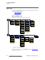
Menu Tree . . . . . . . . . . . . . . . . . . . . . . . . . . . . . . . . . . . . . . . . . . . . . . . . . .
High Level Menu Tree . . . . . . . . . . . . . . . . . . . . . . . . . . . . . . . . . . . .
System Menu Tree . . . . . . . . . . . . . . . . . . . . . . . . . . . . . . . . . . . . . .
Using the Menu System . . . . . . . . . . . . . . . . . . . . . . . . . . . . . . . . . . . . . . . .
Buttons, Tables and Matrices . . . . . . . . . . . . . . . . . . . . . . . . . . . . . . . . . . . .
Button Categories and Colors . . . . . . . . . . . . . . . . . . . . . . . . . . . . . .
Latching, Momentary and Conditional Buttons . . . . . . . . . . . . . . . . .
Value Buttons . . . . . . . . . . . . . . . . . . . . . . . . . . . . . . . . . . . . . . . . . .
Toggle Buttons. . . . . . . . . . . . . . . . . . . . . . . . . . . . . . . . . . . . . . . . . .
Pop-up Buttons . . . . . . . . . . . . . . . . . . . . . . . . . . . . . . . . . . . . . . . . .
Location Buttons . . . . . . . . . . . . . . . . . . . . . . . . . . . . . . . . . . . . . . . .
Summary of Button Types . . . . . . . . . . . . . . . . . . . . . . . . . . . . . . . . .
Tables . . . . . . . . . . . . . . . . . . . . . . . . . . . . . . . . . . . . . . . . . . . . . . . .
Matrices . . . . . . . . . . . . . . . . . . . . . . . . . . . . . . . . . . . . . . . . . . . . . . .
Notes and Error Messages . . . . . . . . . . . . . . . . . . . . . . . . . . . . . . . .
Using the Keypad . . . . . . . . . . . . . . . . . . . . . . . . . . . . . . . . . . . . . . . . . . . . .
Using the Pop-up Keyboard . . . . . . . . . . . . . . . . . . . . . . . . . . . . . . . . . . . . .
Transition Menu . . . . . . . . . . . . . . . . . . . . . . . . . . . . . . . . . . . . . . . . . . . . . .
Transition Menu Access . . . . . . . . . . . . . . . . . . . . . . . . . . . . . . . . . .
Transition Rate Adjustment . . . . . . . . . . . . . . . . . . . . . . . . . . . . . . . .
Transition Curve Adjustment . . . . . . . . . . . . . . . . . . . . . . . . . . . . . . .
Wipe Menu . . . . . . . . . . . . . . . . . . . . . . . . . . . . . . . . . . . . . . . . . . . . . . . . . .
Wipe Menu Access . . . . . . . . . . . . . . . . . . . . . . . . . . . . . . . . . . . . . .
Wipe Patterns . . . . . . . . . . . . . . . . . . . . . . . . . . . . . . . . . . . . . . . . . .
Wipe Functions and Modifiers . . . . . . . . . . . . . . . . . . . . . . . . . . . . . .
Bank . . . . . . . . . . . . . . . . . . . . . . . . . . . . . . . . . . . . . . . . . .
Direction . . . . . . . . . . . . . . . . . . . . . . . . . . . . . . . . . . . . . . .
Edge . . . . . . . . . . . . . . . . . . . . . . . . . . . . . . . . . . . . . . . . . .
Edge Color . . . . . . . . . . . . . . . . . . . . . . . . . . . . . . . . . . . . .
Keyer Menu . . . . . . . . . . . . . . . . . . . . . . . . . . . . . . . . . . . . . . . . . . . . . . . . .
Keyer Menu Access. . . . . . . . . . . . . . . . . . . . . . . . . . . . . . . . . . . . . .
Keyer Status Table . . . . . . . . . . . . . . . . . . . . . . . . . . . . . . . . . . . . . .
Keyer Functions and Modifiers . . . . . . . . . . . . . . . . . . . . . . . . . . . . .
Keyer Selection . . . . . . . . . . . . . . . . . . . . . . . . . . . . . . . . . .
Type . . . . . . . . . . . . . . . . . . . . . . . . . . . . . . . . . . . . . . . . . .
Clip, Gain, Opacity . . . . . . . . . . . . . . . . . . . . . . . . . . . . . . .
Key Fill. . . . . . . . . . . . . . . . . . . . . . . . . . . . . . . . . . . . . . . . .
DVE Keyer Functions . . . . . . . . . . . . . . . . . . . . . . . . . . . . .
Swap Key Settings . . . . . . . . . . . . . . . . . . . . . . . . . . . . . . .
External Key . . . . . . . . . . . . . . . . . . . . . . . . . . . . . . . . . . . .
Copy Key Settings . . . . . . . . . . . . . . . . . . . . . . . . . . . . . . . .
Advanced Key Functions . . . . . . . . . . . . . . . . . . . . . . . . . . . . . . . . . .
Color Background Menu. . . . . . . . . . . . . . . . . . . . . . . . . . . . . . . . . . . . . . . .
FSN Series • User’s Guide • Rev 01
131
132
132
133
134
136
136
137
138
138
139
139
141
142
143
143
144
147
148
149
149
150
151
152
152
152
153
153
155
156
157
158
158
159
159
160
161
162
164
165
166
167
168
169
9
Table of Contents
Color Background Menu Access . . . . . . . . . . . . . . . . . . . . . . . . . . . .
Color Background Functions . . . . . . . . . . . . . . . . . . . . . . . . . . . . . . .
Color Background Selection . . . . . . . . . . . . . . . . . . . . . . . .
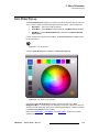
Color Chips . . . . . . . . . . . . . . . . . . . . . . . . . . . . . . . . . . . . .
Color Wheel. . . . . . . . . . . . . . . . . . . . . . . . . . . . . . . . . . . . .
Fine Tuning . . . . . . . . . . . . . . . . . . . . . . . . . . . . . . . . . . . . .
User Colors . . . . . . . . . . . . . . . . . . . . . . . . . . . . . . . . . . . . .
Color Picker Pop-up . . . . . . . . . . . . . . . . . . . . . . . . . . . . . . . . . . . . . . . . . . .
Memory Menu. . . . . . . . . . . . . . . . . . . . . . . . . . . . . . . . . . . . . . . . . . . . . . . .
Memory Menu Access . . . . . . . . . . . . . . . . . . . . . . . . . . . . . . . . . . . .
Memory Menu Description. . . . . . . . . . . . . . . . . . . . . . . . . . . . . . . . .
Enables Menu Description. . . . . . . . . . . . . . . . . . . . . . . . . . . . . . . . .
Enable Descriptions . . . . . . . . . . . . . . . . . . . . . . . . . . . . . .
M/E 1 and M/E 2 Enables . . . . . . . . . . . . . . . . . . .
PGM Enables . . . . . . . . . . . . . . . . . . . . . . . . . . . .
System Enables . . . . . . . . . . . . . . . . . . . . . . . . . .
Aux Enables . . . . . . . . . . . . . . . . . . . . . . . . . . . . .
DVE Enables. . . . . . . . . . . . . . . . . . . . . . . . . . . . .
Selecting Registers . . . . . . . . . . . . . . . . . . . . . . . . . . . . . . . . . . . . . .
Naming Registers . . . . . . . . . . . . . . . . . . . . . . . . . . . . . . . . . . . . . . .
Advanced Memory Functions . . . . . . . . . . . . . . . . . . . . . . . . . . . . . .
Locking and Unlocking Registers . . . . . . . . . . . . . . . . . . . .
Deleting Registers . . . . . . . . . . . . . . . . . . . . . . . . . . . . . . . .
Aux Menu . . . . . . . . . . . . . . . . . . . . . . . . . . . . . . . . . . . . . . . . . . . . . . . . . . .
System Menu . . . . . . . . . . . . . . . . . . . . . . . . . . . . . . . . . . . . . . . . . . . . . . . .
System Menu Description . . . . . . . . . . . . . . . . . . . . . . . . . . . . . . . . .
System Menu Access . . . . . . . . . . . . . . . . . . . . . . . . . . . . .
System Menu Functions . . . . . . . . . . . . . . . . . . . . . . . . . . .
Status Tables . . . . . . . . . . . . . . . . . . . . . . . . . . . . . . . . . . .
Communications Setup Menu . . . . . . . . . . . . . . . . . . . . . . . . . . . . . .
Reference and Output Setup Menu . . . . . . . . . . . . . . . . . . . . . . . . . .
Input Menu. . . . . . . . . . . . . . . . . . . . . . . . . . . . . . . . . . . . . . . . . . . . .
Rear I/O View Description . . . . . . . . . . . . . . . . . . . . . . . . . .
Connector Colors . . . . . . . . . . . . . . . . . . . . . . . . . . . . . . . .
Input Table Description . . . . . . . . . . . . . . . . . . . . . . . . . . . .
Input Menu Functions . . . . . . . . . . . . . . . . . . . . . . . . . . . . .
Default Naming Conventions . . . . . . . . . . . . . . . .
Input Setup Menu for Native Inputs. . . . . . . . . . . . . . . . . . .
Input Color Correction Section . . . . . . . . . . . . . . .
Input Sync Section . . . . . . . . . . . . . . . . . . . . . . . .
Understanding Sync Mode . . . . . . . . . . .
Input Mask Section . . . . . . . . . . . . . . . . . . . . . . . .
Input Setup Menu for Universal Inputs . . . . . . . . . . . . . . . .
Input Capture and Process Panel . . . . . . . . . . . . .
Input Capture and Timing Section . . . . .
Input Processing Section . . . . . . . . . . . .
Input Sizing and Scaling Panel . . . . . . . . . . . . . . .
Input Color Correction Panel. . . . . . . . . . . . . . . . .
Input Setup Menu Tool Bar Functions. . . . . . . . . . . . . . . . .
Input Setup Notes . . . . . . . . . . . . . . . . . . . . . . . . . . . . . . . .
Map Buttons Menu. . . . . . . . . . . . . . . . . . . . . . . . . . . . . . . . . . . . . . .
Button Map Table . . . . . . . . . . . . . . . . . . . . . . . . . . . . . . . .
Map Buttons Menu Functions . . . . . . . . . . . . . . . . . . . . . . .
Map Buttons Keypad . . . . . . . . . . . . . . . . . . . . . . . . . . . . . .
10
170
170
170
170
171
171
172
173
174
175
176
178
180
180
181
182
182
183
183
184
185
185
185
186
188
189
189
190
192
194
197
202
203
204
205
206
208
209
210
211
211
213
214
215
215
218
219
223
223
223
224
225
226
227
FSN Series • User’s Guide • Rev 01
Table of Contents
Mapping Luma Keys and Linear Keys. . . . . . . . . . . . . . . . .
External DSK Setup Menu. . . . . . . . . . . . . . . . . . . . . . . . . . . . . . . . .
External DSK Table. . . . . . . . . . . . . . . . . . . . . . . . . . . . . . .
DSK Cut Setup . . . . . . . . . . . . . . . . . . . . . . . . . . . . . . . . . .
DSK Fill Setup . . . . . . . . . . . . . . . . . . . . . . . . . . . . . . . . . . .
Clean Feed Setup Menu . . . . . . . . . . . . . . . . . . . . . . . . . . . . . . . . . .
Clean Feed Outputs . . . . . . . . . . . . . . . . . . . . . . . . . . . . . .
Assign Button . . . . . . . . . . . . . . . . . . . . . . . . . . . . . . . . . . .
Tally Setup Menu. . . . . . . . . . . . . . . . . . . . . . . . . . . . . . . . . . . . . . . .
Tally Table. . . . . . . . . . . . . . . . . . . . . . . . . . . . . . . . . . . . . .
Tally Setup Menu Functions . . . . . . . . . . . . . . . . . . . . . . . .
DVE Assign Menu . . . . . . . . . . . . . . . . . . . . . . . . . . . . . . . . . . . . . . .
Multiviewer Setup Menu . . . . . . . . . . . . . . . . . . . . . . . . . . . . . . . . . .
Aux Setup Menu . . . . . . . . . . . . . . . . . . . . . . . . . . . . . . . . . . . . . . . .
Rear I/O View Description . . . . . . . . . . . . . . . . . . . . . . . . . .
Aux Table Description . . . . . . . . . . . . . . . . . . . . . . . . . . . . .
Aux Setup Menu Functions . . . . . . . . . . . . . . . . . . . . . . . . .
UOC Setup Menu . . . . . . . . . . . . . . . . . . . . . . . . . . . . . . . .
Output and Process Panel . . . . . . . . . . . . . . . . . .
Output Section . . . . . . . . . . . . . . . . . . . .
Output Processing Section . . . . . . . . . . .
Output Status Section. . . . . . . . . . . . . . .
Output and Process Tool Bar Functions.
Advanced UOC Output Setup Menu . . .
Output Sizing and Scaling Panel . . . . . . . . . . . . .
Output Color Correction Panel . . . . . . . . . . . . . . .
Other Setup Menu . . . . . . . . . . . . . . . . . . . . . . . . . . . . . . . . . . . . . . .
User Preferences Menu . . . . . . . . . . . . . . . . . . . . . . . . . . . . . . . . . . .
User Preferences Table . . . . . . . . . . . . . . . . . . . . . . . . . . .
User Preferences Functions . . . . . . . . . . . . . . . . . . . . . . . .
Diagnostics Menu . . . . . . . . . . . . . . . . . . . . . . . . . . . . . . . . . . . . . . .
T-Bar, Joystick and Knobs . . . . . . . . . . . . . . . . . . . . . . . . .
Calibrate Touch Screen. . . . . . . . . . . . . . . . . . . . . . . . . . . .
LEDs, Buttons and Displays . . . . . . . . . . . . . . . . . . . . . . . .
Tallies . . . . . . . . . . . . . . . . . . . . . . . . . . . . . . . . . . . . . . . . .
GPIO . . . . . . . . . . . . . . . . . . . . . . . . . . . . . . . . . . . . . . . . . .
View Errors . . . . . . . . . . . . . . . . . . . . . . . . . . . . . . . . . . . . .
View Log . . . . . . . . . . . . . . . . . . . . . . . . . . . . . . . . . . . . . . .
Software Menu. . . . . . . . . . . . . . . . . . . . . . . . . . . . . . . . . . . . . . . . . .
Software Table . . . . . . . . . . . . . . . . . . . . . . . . . . . . . . . . . .
Software Functions . . . . . . . . . . . . . . . . . . . . . . . . . . . . . . .
Output Test Patterns Menu . . . . . . . . . . . . . . . . . . . . . . . . . . . . . . . .
Lock/Unlock Panel . . . . . . . . . . . . . . . . . . . . . . . . . . . . . . . . . . . . . . .
Save All . . . . . . . . . . . . . . . . . . . . . . . . . . . . . . . . . . . . . . . . . . . . . . .
Backup and Restore Menu . . . . . . . . . . . . . . . . . . . . . . . . . . . . . . . .
Reset Menu . . . . . . . . . . . . . . . . . . . . . . . . . . . . . . . . . . . . . . . . . . . .
Factory Default Settings . . . . . . . . . . . . . . . . . . . . . . . . . . .
System Shutdown . . . . . . . . . . . . . . . . . . . . . . . . . . . . . . . . . . . . . . .
Help Menu and Shortcuts . . . . . . . . . . . . . . . . . . . . . . . . . . . . . . . . . . . . . . .
Shortcuts . . . . . . . . . . . . . . . . . . . . . . . . . . . . . . . . . . . . . . . . . . . . . .
FSN Series • User’s Guide • Rev 01
228
229
230
230
231
232
232
233
235
236
237
238
239
240
241
241
242
243
244
244
245
245
246
247
249
252
253
254
255
255
257
258
259
260
262
263
264
266
268
269
269
270
272
272
273
274
275
276
277
278
11
Table of Contents
`Ü~éíÉê=S
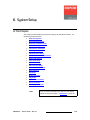
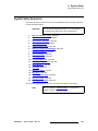
póëíÉã=pÉíìéK=K=K=K=K=K=K=K=K=K=K=K=K=K=K=K=K=K=K=K=K=K=K=K=K=K=K=K=K=K=K=K=K=K=K=K=K=K=KOTV
In This Chapter . . . . . . . . . . . . . . . . . . . . . . . . . . . . . . . . . . . . . . . . . . . . . . .
Setup Prerequisites . . . . . . . . . . . . . . . . . . . . . . . . . . . . . . . . . . . . . . . . . . .
System Setup Sequence . . . . . . . . . . . . . . . . . . . . . . . . . . . . . . . . . . . . . . .
Power Up and Status Check . . . . . . . . . . . . . . . . . . . . . . . . . . . . . . . . . . . .
Return to Factory Default . . . . . . . . . . . . . . . . . . . . . . . . . . . . . . . . . . . . . . .
Touch Screen Calibration . . . . . . . . . . . . . . . . . . . . . . . . . . . . . . . . . . . . . . .
Communications Setup . . . . . . . . . . . . . . . . . . . . . . . . . . . . . . . . . . . . . . . .
Restoring the System . . . . . . . . . . . . . . . . . . . . . . . . . . . . . . . . . . . . . . . . . .
Reference Video and Output Setup . . . . . . . . . . . . . . . . . . . . . . . . . . . . . . .
Output Test Patterns . . . . . . . . . . . . . . . . . . . . . . . . . . . . . . . . . . . . . . . . . .
Clean Feed Setup. . . . . . . . . . . . . . . . . . . . . . . . . . . . . . . . . . . . . . . . . . . . .
Native Input Setup . . . . . . . . . . . . . . . . . . . . . . . . . . . . . . . . . . . . . . . . . . . .
Universal Input Setup . . . . . . . . . . . . . . . . . . . . . . . . . . . . . . . . . . . . . . . . . .
External DSK Input Setup. . . . . . . . . . . . . . . . . . . . . . . . . . . . . . . . . . . . . . .
Button Mapping . . . . . . . . . . . . . . . . . . . . . . . . . . . . . . . . . . . . . . . . . . . . . .
Aux Setup . . . . . . . . . . . . . . . . . . . . . . . . . . . . . . . . . . . . . . . . . . . . . . . . . . .
Multiviewer Setup . . . . . . . . . . . . . . . . . . . . . . . . . . . . . . . . . . . . . . . . . . . . .
Tally Setup . . . . . . . . . . . . . . . . . . . . . . . . . . . . . . . . . . . . . . . . . . . . . . . . . .
User Preferences Setup . . . . . . . . . . . . . . . . . . . . . . . . . . . . . . . . . . . . . . . .
Saving the Setup . . . . . . . . . . . . . . . . . . . . . . . . . . . . . . . . . . . . . . . . . . . . .
Backing up the System . . . . . . . . . . . . . . . . . . . . . . . . . . . . . . . . . . . . . . . . .
`Ü~éíÉê=T
léÉê~íáçåë =K=K=K=K=K=K=K=K=K=K=K=K=K=K=K=K=K=K=K=K=K=K=K=K=K=K=K=K=K=K=K=K=K=K=K=K=K=K=K=K=KPMT
In This Chapter . . . . . . . . . . . . . . . . . . . . . . . . . . . . . . . . . . . . . . . . . . . . . . .
Quick Setup and Operations . . . . . . . . . . . . . . . . . . . . . . . . . . . . . . . . . . . .
Quick Function Reference . . . . . . . . . . . . . . . . . . . . . . . . . . . . . . . . . . . . . .
Understanding Button Color . . . . . . . . . . . . . . . . . . . . . . . . . . . . . . . . . . . . .
Understanding Switcher Layers . . . . . . . . . . . . . . . . . . . . . . . . . . . . . . . . . .
Understanding Flip-flop Mode . . . . . . . . . . . . . . . . . . . . . . . . . . . . . . . . . . .
Understanding Tally . . . . . . . . . . . . . . . . . . . . . . . . . . . . . . . . . . . . . . . . . . .
Understanding Error Messages . . . . . . . . . . . . . . . . . . . . . . . . . . . . . . . . . .
Working with Pop-ups. . . . . . . . . . . . . . . . . . . . . . . . . . . . . . . . . . . . . . . . . .
Using the Keypad . . . . . . . . . . . . . . . . . . . . . . . . . . . . . . . . . . . . . . . . . . . . .
Understanding Press and Hold. . . . . . . . . . . . . . . . . . . . . . . . . . . . . . . . . . .
Understanding Lookahead Preview . . . . . . . . . . . . . . . . . . . . . . . . . . . . . . .
Lookahead Preview Overview . . . . . . . . . . . . . . . . . . . . . . . . . . . . . .
Lookahead Preview Tutorial . . . . . . . . . . . . . . . . . . . . . . . . . . . . . . .
Example 1: BG Lookahead . . . . . . . . . . . . . . . . . . . . . . . .
Example 2: KEY 1 Lookahead . . . . . . . . . . . . . . . . . . . . . .
Example 3: KEY 2 Lookahead . . . . . . . . . . . . . . . . . . . . . .
Example 4: BG Lookahead, Transition Under Key. . . . . . .
Example 5: Combined Lookahead . . . . . . . . . . . . . . . . . . .
Example 6: Continued Practice . . . . . . . . . . . . . . . . . . . . .
Understanding the T-Bar and Transition LEDs. . . . . . . . . . . . . . . . . . . . . . .
Manual Transitions . . . . . . . . . . . . . . . . . . . . . . . . . . . . . . . . . . . . . .
Automatic Transitions . . . . . . . . . . . . . . . . . . . . . . . . . . . . . . . . . . . .
Physical and Virtual T-Bar Position . . . . . . . . . . . . . . . . . . . . . . . . . .
Example 1: Normal T-Bar movement . . . . . . . . . . . . . . . . .
Example 2: T-Bar movement with memory registers . . . . .
12
279
280
281
282
283
284
285
286
287
289
290
291
293
296
297
298
301
303
304
305
305
307
308
310
311
312
314
315
316
317
317
318
319
319
320
320
321
322
323
324
324
325
325
325
326
326
327
FSN Series • User’s Guide • Rev 01
Table of Contents
Transition LED Notes. . . . . . . . . . . . . . . . . . . . . . . . . . . . . . . . . . . . .
Using Re-entry . . . . . . . . . . . . . . . . . . . . . . . . . . . . . . . . . . . . . . . . . . . . . . .
Working with Cuts. . . . . . . . . . . . . . . . . . . . . . . . . . . . . . . . . . . . . . . . . . . . .
Setting Transition Rates and Curves . . . . . . . . . . . . . . . . . . . . . . . . . . . . . .
Working with Mixes. . . . . . . . . . . . . . . . . . . . . . . . . . . . . . . . . . . . . . . . . . . .
Manual Mix . . . . . . . . . . . . . . . . . . . . . . . . . . . . . . . . . . . . . . . . . . . .
Automatic Mix . . . . . . . . . . . . . . . . . . . . . . . . . . . . . . . . . . . . . . . . . .
Working with Wipes . . . . . . . . . . . . . . . . . . . . . . . . . . . . . . . . . . . . . . . . . . .
Wipe Setup . . . . . . . . . . . . . . . . . . . . . . . . . . . . . . . . . . . . . . . . . . . .
Manual Wipe . . . . . . . . . . . . . . . . . . . . . . . . . . . . . . . . . . . . . . . . . . .
Automatic Wipe . . . . . . . . . . . . . . . . . . . . . . . . . . . . . . . . . . . . . . . . .
Working with Keys . . . . . . . . . . . . . . . . . . . . . . . . . . . . . . . . . . . . . . . . . . . .
Key Setup . . . . . . . . . . . . . . . . . . . . . . . . . . . . . . . . . . . . . . . . . . . . .
Manual Mix Key . . . . . . . . . . . . . . . . . . . . . . . . . . . . . . . . . . . . . . . . .
Automatic Mix Key . . . . . . . . . . . . . . . . . . . . . . . . . . . . . . . . . . . . . . .
Manual Wipe Key. . . . . . . . . . . . . . . . . . . . . . . . . . . . . . . . . . . . . . . .
Automatic Wipe Key . . . . . . . . . . . . . . . . . . . . . . . . . . . . . . . . . . . . .
Direct Control Keys . . . . . . . . . . . . . . . . . . . . . . . . . . . . . . . . . . . . . .
Working with Memory Registers . . . . . . . . . . . . . . . . . . . . . . . . . . . . . . . . . .
Memory Register Overview . . . . . . . . . . . . . . . . . . . . . . . . . . . . . . . .
Storing Memory Registers . . . . . . . . . . . . . . . . . . . . . . . . . . . . . . . . .
Store, Bypass Enables, Use Default Name. . . . . . . . . . . . .
Store, Bypass Enables, Enter Custom Name . . . . . . . . . . .
Store, Set Enables, Enter Custom Name . . . . . . . . . . . . . .
Memory Store Notes . . . . . . . . . . . . . . . . . . . . . . . . . . . . . .
Recalling Memory Registers . . . . . . . . . . . . . . . . . . . . . . . . . . . . . . .
Recall, Bypass Enables. . . . . . . . . . . . . . . . . . . . . . . . . . . .
Recall, Adjust Enables . . . . . . . . . . . . . . . . . . . . . . . . . . . .
Memory Recall Notes . . . . . . . . . . . . . . . . . . . . . . . . . . . . .
Viewing Memory Registers . . . . . . . . . . . . . . . . . . . . . . . . . . . . . . . .
Locking and Unlocking Memory Registers . . . . . . . . . . . . . . . . . . . .
Deleting Memory Registers . . . . . . . . . . . . . . . . . . . . . . . . . . . . . . . .
Working with Aux Buses . . . . . . . . . . . . . . . . . . . . . . . . . . . . . . . . . . . . . . . .
Selecting Clean Feed Outputs . . . . . . . . . . . . . . . . . . . . . . . . . . . . . . . . . . .
Using Custom Control Functions . . . . . . . . . . . . . . . . . . . . . . . . . . . . . . . . .
M/E 2 Control on the FSN-150 . . . . . . . . . . . . . . . . . . . . . . . . . . . . . . . . . . .
Backing Up and Restoring the System . . . . . . . . . . . . . . . . . . . . . . . . . . . . .
Backing Up the System . . . . . . . . . . . . . . . . . . . . . . . . . . . . . . . . . . .
Restoring the System . . . . . . . . . . . . . . . . . . . . . . . . . . . . . . . . . . . .
`Ü~éíÉê=U
327
328
329
330
331
331
331
332
332
332
332
333
334
335
335
335
336
336
337
337
339
339
340
340
341
342
342
342
343
344
344
345
346
347
348
349
350
350
351
asb=léÉê~íáçåëK=K=K=K=K=K=K=K=K=K=K=K=K=K=K=K=K=K=K=K=K=K=K=K=K=K=K=K=K=K=K=K=K=K=K=K=KPRP
In This Chapter . . . . . . . . . . . . . . . . . . . . . . . . . . . . . . . . . . . . . . . . . . . . . . .
Introduction to the DVE . . . . . . . . . . . . . . . . . . . . . . . . . . . . . . . . . . . . . . . .
DVE Workflow Overview . . . . . . . . . . . . . . . . . . . . . . . . . . . . . . . . . .
DVE Modes and Features . . . . . . . . . . . . . . . . . . . . . . . . . . . . . . . . .
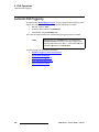
Multiple Ways to Trigger . . . . . . . . . . . . . . . . . . . . . . . . . . . . . . . . . .
M/E Bank Triggers. . . . . . . . . . . . . . . . . . . . . . . . . . . . . . . .
PGM Bank Triggers. . . . . . . . . . . . . . . . . . . . . . . . . . . . . . .
DVE Effect Durations . . . . . . . . . . . . . . . . . . . . . . . . . . . . . . . . . . . . .
DVE Morphing . . . . . . . . . . . . . . . . . . . . . . . . . . . . . . . . . . . . . . . . . .
DVE Coordinate Space . . . . . . . . . . . . . . . . . . . . . . . . . . . . . . . . . . .
FSN Series • User’s Guide • Rev 01
353
354
354
355
357
357
358
359
359
360
13
Table of Contents
Joystick Control . . . . . . . . . . . . . . . . . . . . . . . . . . . . . . . . . . . . . . . . .
DVE Menu Orientation . . . . . . . . . . . . . . . . . . . . . . . . . . . . . . . . . . . . . . . . .
DVE Assign Menu . . . . . . . . . . . . . . . . . . . . . . . . . . . . . . . . . . . . . . .
DVE Main Menu — Size and Position Panel . . . . . . . . . . . . . . . . . . .
Common DVE Menu Components . . . . . . . . . . . . . . . . . . .
Functional Tabs . . . . . . . . . . . . . . . . . . . . . . . . . .
DVE Status Table . . . . . . . . . . . . . . . . . . . . . . . . .
Keyframe Editing Section . . . . . . . . . . . . . . . . . . .
Tool Bar Functions . . . . . . . . . . . . . . . . . . . . . . . .
Size and Position Adjustments . . . . . . . . . . . . . . . . . . . . . .
Size Presets . . . . . . . . . . . . . . . . . . . . . . . . . . . . .
Position Presets . . . . . . . . . . . . . . . . . . . . . . . . . .
Aspect Ratio . . . . . . . . . . . . . . . . . . . . . . . . . . . . .
Manual Size and Position . . . . . . . . . . . . . . . . . . .
Effect Setup Panel . . . . . . . . . . . . . . . . . . . . . . . . . . . . . . . . . . . . . . .
Pan Zoom Source Panel . . . . . . . . . . . . . . . . . . . . . . . . . . . . . . . . . .
Mask Panel . . . . . . . . . . . . . . . . . . . . . . . . . . . . . . . . . . . . . . . . . . . .
Border Shadow Opacity Panel. . . . . . . . . . . . . . . . . . . . . . . . . . . . . .
Border Section. . . . . . . . . . . . . . . . . . . . . . . . . . . . . . . . . . .
Shadow Section . . . . . . . . . . . . . . . . . . . . . . . . . . . . . . . . .
Opacity Section . . . . . . . . . . . . . . . . . . . . . . . . . . . . . . . . . .
Shot Box Menu . . . . . . . . . . . . . . . . . . . . . . . . . . . . . . . . . . . . . . . . .
Advanced DVE Menu — Color Effects Panel . . . . . . . . . . . . . . . . . .
Advanced DVE Menu — DVE Extras Panel . . . . . . . . . . . . . . . . . . .
Keyframe Freeze Behavior . . . . . . . . . . . . . . . . . . . . . . . . .
DVE Links . . . . . . . . . . . . . . . . . . . . . . . . . . . . . . . . . . . . . . . . . . . . .
Assigning DVE Channels to Keyers . . . . . . . . . . . . . . . . . . . . . . . . . . . . . . .
Selecting the Keyer Mode . . . . . . . . . . . . . . . . . . . . . . . . . . . . . . . . . . . . . .
Programming DVE Effects . . . . . . . . . . . . . . . . . . . . . . . . . . . . . . . . . . . . . .
Programming Single Keyframe Effects . . . . . . . . . . . . . . . . . . . . . . .
Programming Dual Keyframe Effects . . . . . . . . . . . . . . . . . . . . . . . .
Creating Dual Keyframe Effects from the Shot Box. . . . . . . . . . . . . .
Editing Keyframes . . . . . . . . . . . . . . . . . . . . . . . . . . . . . . . . . . . . . . . . . . . .
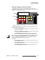
Automatic DVE Triggering . . . . . . . . . . . . . . . . . . . . . . . . . . . . . . . . . . . . . .
Automatic Triggering via the Control Panel . . . . . . . . . . . . . . . . . . . .
Trigger Setup and Display . . . . . . . . . . . . . . . . . . . . . . . . . . . . . . . . .
Trigger Only Transition . . . . . . . . . . . . . . . . . . . . . . . . . . . .
Mix-key-trigger Transition . . . . . . . . . . . . . . . . . . . . . . . . . .
Wipe-key-trigger Transition . . . . . . . . . . . . . . . . . . . . . . . . .
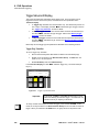
Automatic DVE Trigger Rules . . . . . . . . . . . . . . . . . . . . . . . . . . . . . .
Using Automatic DVE Triggers . . . . . . . . . . . . . . . . . . . . . . . . . . . . .
Trigger an Effect on Keyer 1 Only . . . . . . . . . . . . . . . . . . . .
Trigger an Effect on Keyer 2 Only . . . . . . . . . . . . . . . . . . . .
Trigger Effects on both Keyers . . . . . . . . . . . . . . . . . . . . . .
Mix Key and Trigger an Effect on Keyer 1. . . . . . . . . . . . . .
Mix Key and Trigger an Effect on Keyer 2. . . . . . . . . . . . . .
Mix Key and Trigger Effects on both Keyers . . . . . . . . . . . .
Mix BG and Keyer 1, and Trigger Effect on Keyer 1 . . . . . .
Mix BG and Keyer 2, and Trigger Effect on Keyer 2 . . . . . .
Mix BG and both Keyers, Trigger Effects on both Keyers. .
Wipe Trigger Options . . . . . . . . . . . . . . . . . . . . . . . . . . . . .
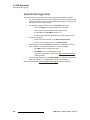
Tap In, Tap Out Functions . . . . . . . . . . . . . . . . . . . . . . . . . . . . . . . . .
Tap In, Tap Out Rules . . . . . . . . . . . . . . . . . . . . . . . . . . . . .
14
361
362
363
365
366
366
367
367
368
369
369
370
370
371
372
373
375
377
378
379
380
381
383
385
387
388
389
390
391
391
392
393
394
396
397
398
398
399
399
400
401
401
402
402
403
403
404
404
405
405
406
407
407
FSN Series • User’s Guide • Rev 01
Table of Contents
Tap in, Tap Out Examples. . . . . . . . . . . . . . . . . . . . . . . . . .
Mix KEY 1 and trigger KEY 2 . . . . . . . . . . . . . . . .
Mix BG, trigger KEY 1, mix-key-trigger KEY 2 . . .
Wipe-key-trigger KEY 1, wipe KEY 2 . . . . . . . . . .
`Ü~éíÉê=V
jìäíáîáÉïÉê=léÉê~íáçåë =K=K=K=K=K=K=K=K=K=K=K=K=K=K=K=K=K=K=K=K=K=K=K=K=K=K=K=K=KQNN
In This Chapter . . . . . . . . . . . . . . . . . . . . . . . . . . . . . . . . . . . . . . . . . . . . . . .
Introduction to the Multiviewer . . . . . . . . . . . . . . . . . . . . . . . . . . . . . . . . . . .
Multiviewer Menu Orientation . . . . . . . . . . . . . . . . . . . . . . . . . . . . . . . . . . . .
Multiviewer Setup Menu . . . . . . . . . . . . . . . . . . . . . . . . . . . . . . . . . .
Multiviewer Output Setup Menu. . . . . . . . . . . . . . . . . . . . . . . . . . . . .
Select Layout Menu . . . . . . . . . . . . . . . . . . . . . . . . . . . . . . . . . . . . . .
Select Colors Menu . . . . . . . . . . . . . . . . . . . . . . . . . . . . . . . . . . . . . .
Clock Setup Menu . . . . . . . . . . . . . . . . . . . . . . . . . . . . . . . . . . . . . . .
Assign Source Keypad . . . . . . . . . . . . . . . . . . . . . . . . . . . . . . . . . . .
Multiviewer Setup . . . . . . . . . . . . . . . . . . . . . . . . . . . . . . . . . . . . . . . . . . . . .
Multiviewer Memory . . . . . . . . . . . . . . . . . . . . . . . . . . . . . . . . . . . . . . . . . . .
`Ü~éíÉê=NM
411
412
414
415
417
418
420
421
422
423
423
réÇ~íáåÖ=pçÑíï~êÉ K=K=K=K=K=K=K=K=K=K=K=K=K=K=K=K=K=K=K=K=K=K=K=K=K=K=K=K=K=K=K=K=K=KQOR
In This Chapter . . . . . . . . . . . . . . . . . . . . . . . . . . . . . . . . . . . . . . . . . . . . . . .
Software Update Overview . . . . . . . . . . . . . . . . . . . . . . . . . . . . . . . . . . . . . .
Hardware Requirements. . . . . . . . . . . . . . . . . . . . . . . . . . . . . . . . . . . . . . . .
Downloading Software . . . . . . . . . . . . . . . . . . . . . . . . . . . . . . . . . . . . . . . . .
Via FTP Site. . . . . . . . . . . . . . . . . . . . . . . . . . . . . . . . . . . . . . . . . . . .
Via Web Site . . . . . . . . . . . . . . . . . . . . . . . . . . . . . . . . . . . . . . . . . . .
Updating Control Panel Software . . . . . . . . . . . . . . . . . . . . . . . . . . . . . . . . .
Updating FSN-1400 Software. . . . . . . . . . . . . . . . . . . . . . . . . . . . . . . . . . . .
Conditional Updates . . . . . . . . . . . . . . . . . . . . . . . . . . . . . . . . . . . . . . . . . . .
^ééÉåÇáñ=^=
408
408
409
409
425
426
426
427
427
428
429
430
430
péÉÅáÑáÅ~íáçåëK=K=K=K=K=K=K=K=K=K=K=K=K=K=K=K=K=K=K=K=K=K=K=K=K=K=K=K=K=K=K=K=K=K=K=K=K=K=KQPN
In This Appendix. . . . . . . . . . . . . . . . . . . . . . . . . . . . . . . . . . . . . . . . . . . . . .
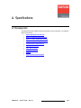
System Specifications Overview . . . . . . . . . . . . . . . . . . . . . . . . . . . . . . . . .
Reference Video Input Specifications. . . . . . . . . . . . . . . . . . . . . . . . . . . . . .
Reference Video Output Specifications . . . . . . . . . . . . . . . . . . . . . . . . . . . .
Physical and Electrical Specifications . . . . . . . . . . . . . . . . . . . . . . . . . . . . .
FSN-1400 . . . . . . . . . . . . . . . . . . . . . . . . . . . . . . . . . . . . . . . . . . . . .
FSN-150 . . . . . . . . . . . . . . . . . . . . . . . . . . . . . . . . . . . . . . . . . . . . . .
Touch Screen Display . . . . . . . . . . . . . . . . . . . . . . . . . . . . . . . . . . . .
Touch Screen Display Stand . . . . . . . . . . . . . . . . . . . . . . . . . . . . . . .
Communications Specifications . . . . . . . . . . . . . . . . . . . . . . . . . . . . . . . . . .
Agency Specifications . . . . . . . . . . . . . . . . . . . . . . . . . . . . . . . . . . . . . . . . .
Cable Specifications . . . . . . . . . . . . . . . . . . . . . . . . . . . . . . . . . . . . . . . . . . .
Delay Specifications . . . . . . . . . . . . . . . . . . . . . . . . . . . . . . . . . . . . . . . . . . .
NIC Delay . . . . . . . . . . . . . . . . . . . . . . . . . . . . . . . . . . . . . . . . . . . . .
UIC Delay . . . . . . . . . . . . . . . . . . . . . . . . . . . . . . . . . . . . . . . . . . . . .
Pinouts . . . . . . . . . . . . . . . . . . . . . . . . . . . . . . . . . . . . . . . . . . . . . . . . . . . . .
Analog 15-pin D Connector . . . . . . . . . . . . . . . . . . . . . . . . . . . . . . . .
DVI-I Connector . . . . . . . . . . . . . . . . . . . . . . . . . . . . . . . . . . . . . . . . .
FSN Series • User’s Guide • Rev 01
431
432
433
434
435
435
435
436
436
437
437
437
438
438
438
439
439
440
15
Table of Contents
Ethernet Connector . . . . . . . . . . . . . . . . . . . . . . . . . . . . . . . . . . . . . .
Serial Connectors . . . . . . . . . . . . . . . . . . . . . . . . . . . . . . . . . . . . . . .
Tally Connector . . . . . . . . . . . . . . . . . . . . . . . . . . . . . . . . . . . . . . . . .
GPIO Connector . . . . . . . . . . . . . . . . . . . . . . . . . . . . . . . . . . . . . . . .
Input and Output Format Tables. . . . . . . . . . . . . . . . . . . . . . . . . . . . . . . . . .
UIC Input and UOC Output Formats . . . . . . . . . . . . . . . . . . . . . . . . .
NIC Input Formats, UIC Input Formats (BNC) . . . . . . . . . . . . . . . . . .
Output Formats . . . . . . . . . . . . . . . . . . . . . . . . . . . . . . . . . . . . . . . . .
^ééÉåÇáñ=_=
`çåí~Åí=fåÑçêã~íáçå=K=K=K=K=K=K=K=K=K=K=K=K=K=K=K=K=K=K=K=K=K=K=K=K=K=K=K=K=K=K=K=K=KQRN
In This Appendix. . . . . . . . . . . . . . . . . . . . . . . . . . . . . . . . . . . . . . . . . . . . . .
Warranty . . . . . . . . . . . . . . . . . . . . . . . . . . . . . . . . . . . . . . . . . . . . . . . . . . . .
Return Material Authorization (RMA) . . . . . . . . . . . . . . . . . . . . . . . . . . . . . .
Contact Information . . . . . . . . . . . . . . . . . . . . . . . . . . . . . . . . . . . . . . . . . . .
fåÇÉñ
16
441
442
443
444
445
445
449
449
451
451
451
452
=K=K=K=K=K=K=K=K=K=K=K=K=K=K=K=K=K=K=K=K=K=K=K=K=K=K=K=K=K=K=K=K=K=K=K=K=K=K=K=K=K=K=K=K=K=K=K=K=K=K=K=KQRP
FSN Series • User’s Guide • Rev 01
NK==fåíêçÇìÅíáçå
få=qÜáë=`Ü~éíÉê
This chapter is designed to introduce you to the FSN Series User’s Guide. Areas to be
covered are:
•
•
•
•
•
•
•
•
•
Software Version
Chapter Structure
How to Use This Guide
Conventions
Glossary of Switcher Terms
About the FSN Series
New Feature Review
Connectivity Diagrams
Application Questions
FSN Series • User’s Guide • Rev 01
17
NK==fåíêçÇìÅíáçå
Software Version
pçÑíï~êÉ=sÉêëáçå
This version of the FSN Series User’s Guide is based on software version 3.0.
`Ü~éíÉê=píêìÅíìêÉ
The following chapters provide instructions for all aspects of FSN Series operations:
18
•
Chapter 1, “Introduction” provides a system overview, a list of features, and
system connectivity diagrams.
•
Chapter 2, “FSN-1400 Orientation” on page 33 provides detailed explanations of
the system’s chassis and internal cards.
•
Chapter 3, “Control Panel Orientation” on page 67 provides detailed
explanations of each control panel’s sections and functions.
•
Chapter 4, “Installation” on page 103 provides comprehensive system installation
instructions.
•
Chapter 5, “Menu Orientation” on page 131 provides menu trees, plus
comprehensive explanations of each menu and function.
•
Chapter 6, “System Setup” on page 279 provides detailed instructions for setting
up system inputs, outputs and communications.
•
Chapter 7, “Operations” on page 307 provides comprehensive system operating
instructions.
•
Chapter 8, “DVE Operations” on page 353 provides full instructions on setting up
and operating the optional 2D DVE.
•
Chapter 9, “Multiviewer Operations” on page 411 provides full instructions on
setting up and operating the optional Multiviewer.
•
Chapter 10, “Updating Software” on page 425 outlines procedures for upgrading
system software components.
•
•
Appendix A, “Specifications” on page 431 lists the FSN Series’ specifications.
Appendix B, “Contact Information” on page 451 lists important Barco contact,
RMA, warranty and technical support details.
FSN Series • User’s Guide • Rev 01
NK==fåíêçÇìÅíáçå
How to Use This Guide
eçï=íç=rëÉ=qÜáë=dìáÇÉ
This section provides important tips for streamlining your use of this User’s Guide in its
electronic “PDF” form.
k~îáÖ~íáåÖ
Use Acrobat Reader’s “bookmarks” to navigate to the desired location. All chapter files
have the same bookmark structure for instant navigation to any section. Please note:
•
•
Extensive hyperlinks are provided within the chapters.
•
Use the “Previous Page” and “Next Page” buttons to go to the previous or next
page within a file.
•
Use Acrobat’s extensive search capabilities, such as the “Find” tool and “Search
Index” tool to perform comprehensive searches as required.
Use Acrobat’s “Go to Previous View” and “Return to Next View” buttons to trace
your complete navigational path.
q~ÄäÉ=çÑ=`çåíÉåíë=~åÇ=fåÇÉñ
Use the Table of Contents bookmarks to navigate a desired topic. Click any item to
instantly jump to that section of the guide. You can also use the Index to jump to specific
topics within a chapter. Each page number in the Index is a hyperlink.
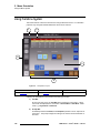
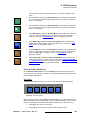
`çåîÉåíáçåë=
The following conventions are used throughout this guide:
•
•
•
The symbol denotes an operations procedure.
The symbol S denotes an example.
Entries written in bold-face letters denote physical buttons, chassis connectors
and “sections” on the control panel.
S Press DSK to ...
•
Entries written between braces denote buttons on the Touch Screen.
S Press {Edge Color} to ...
•
A sequence of button presses on the control panel is denoted by the button
names, separated by commas.
S Press STORE, M/E 1, #, ENTER to ...
•
A “press and hold” sequence involving two buttons is denoted by the + symbol in
between button names.
S Press MIX + FX TRIG to ...
•
A sequence of button presses on the Touch Screen is denoted by the button
names, separated by arrows.
S Press {System} > {Input Setup} to ...
FSN Series • User’s Guide • Rev 01
19
NK==fåíêçÇìÅíáçå
Glossary of Switcher Terms
däçëë~êó=çÑ=pïáíÅÜÉê=qÉêãë=
The following terms and abbreviations are used throughout this guide:
•
3G — A 3 Gbit/s serial digital 10-bit or 12-bit video interface (SMPTE 424M and
425M).
•
AUX (Auxiliary) Bus — AUX buses are extra switching buses that allow video
signals connected to the switcher to be routed to external equipment such as
VTRs, monitors, projectors, etc.
•
Bank — a name for the three combined individual buses in an M/E, including the
PGM bus, the PST bus and the KEY bus.
•
BG (Background) — The switcher bus on an M/E bank that selects the on-line (or
on-air) output signal.
•
Chroma Key — A type of key where the hole-cutting information is derived from a
color rather than from a video level. An common example on television, is when
the weatherman appears to be standing in front of a map. The map itself is a
video signal, and the weatherman is in fact standing in front of a green (or blue)
screen. On the switcher, the Chroma Key process electronically subtracts the
color from the foreground image, and replaces it with video from the background
image to form a composite image.
•
Clip, Gain, Opacity — In switcher terminology, the process of fine-tuning a key of
any type (luminance, linear, or chroma). Clipping sets the threshold for the holecutting circuitry, while "gain" defines the range and sensitivity of adjustment. The
"opacity" is the transparency or density of the key, as revealed over a background.
•
Chassis Cards — In addition to the required M/E and System cards, the
following cards that can be installed in the chassis, enabling you to configure the
switcher in many flexible ways. These cards are abbreviated as follows:
~
~
~
~
~
20
NIC (Native Input Card) — provides eight native video inputs.
UIC (Universal Input Card) — provides two universal scaler inputs.
UOC (Universal Output Card) — provides two universal auxiliary outputs.
NAC (Native Aux Output Card) — provides eight native auxiliary outputs.
DVE (Digital Video Effects) — provides two “2D” DVE channels.
•
CLN (Clean Feed) — An output of an M/E that originates upstream of the M/E’s
keyers. For example, if the output of M/E 1 is Camera 1 plus a key, the “clean”
output is Camera 1 only, minus the key.
•
Computer Video — A generic term indicating video that originates from a
computer platform. A progressive scan signal that follows VESA (Video
Electronics Standards Association) standards, with typical resolutions of 800 x
600, 1024 x 768, 1280 x 1024, etc.
•
Crosspoint — The video switch (or button) that selects the input required on a
particular switcher bus.
•
•
Cut — an instantaneous switch from one video source to another.
•
DSK (Downstream Keyer) — A DSK is a key that is electronically located after all
other switcher functions — visually on top of all other layers and buses. Any
operations performed “upstream” on the switcher M/Es will not affect the
downstream key video.
DA (Distribution Amplifier) — A video device that inputs one video signal, and
outputs multiple “identical” signals.
FSN Series • User’s Guide • Rev 01
NK==fåíêçÇìÅíáçå
Glossary of Switcher Terms
•
DVE (Digital Video Effects) — A special effects generator with the ability to create
PIP effects, reduce and enlarge images, create borders and shadows around
those images, and create keyframes for motion paths. See PIP and Keyframe for
additional information.
•
•
•
EXT (External) — A digital key input that is dedicated to the DSK.
•
GPIO (General Purpose Input/Output) — One or more communications ports that
control input and output "triggering." For example, with a GPI (input) trigger, an
external peripheral device can trigger a specified switcher function. With a GPO
(output) trigger, the switcher can trigger an external device.
•
GUI (Graphical User Interface) — A term that describes a status display based on
graphics and icons, rather than strictly on numbers and letters.
•
HD-SDI (High Definition Serial Digital Interface) — a high definition SDI signal
(SMPTE 292M). Example formats are 720p, 1080i, and 1080p.
•
Keyframe — In a PIP “move,” a keyframe is a point where an action or change
occurs. For example, when a PIP moves from the upper right corner to full
screen, keyframe 1 is the upper right position, and keyframe 2 is the full screen
position of the PIP.
•
Keying — The process of superimposing video from one source (the foreground)
on top of another source (the background).
•
Key Fill — The video which fills the hole cut by the keying circuitry. Typically,
switchers provide a variety of choices for the fill source — internal mattes, external
video, or "self" fill are several examples.
•
Key Mask — A key modification system that protects a portion of the foreground
video from being keyed, using the switcher’s internal pattern system.
•
Key Signal — also known as Key Source. The signal that electronically cuts the
hole in the background video signal. Key signals typically originate from external
inputs such as character generators or cameras.
•
Linear Key — a keying mode in which the edges of anti-aliased key sources
(such as character generators) are reproduced clearly. Typically, two separate
signals are required from a linear key source: a cut and a fill.
•
M/E (Mix/Effects) — The section (or "bank") of a video switcher where video
signals are processed to select inputs and create mixes, wipes, keys and other
effects. An M/E is essentially a video layer that can be combined with other M/Es
(layers) to form the entire output of the switcher.
•
Menu — A term used to describe buttons and functions on the high-resolution
color LCD touch screen.
•
Mix — also known as a Dissolve. A transition between two video sources in
which one source fades out as the other fades in.
•
Multiviewer (MVR) — a monitoring system that enables multiple sources (input
and outputs) to be displayed on one or two monitors, eliminating the need for
individual source monitors. By utilizing different arrays of PIPs, users can select
the preferred multiviewer “look,” and streamline control room operations.
•
Native Resolution — The resolution to which all processing is set within the
switcher frame, e.g., SD-SDI (SMPTE 259M, Level C) or HD-SDI (SMPTE 292M).
Fader — see T-Bar.
FTB (Fade to Black) — The button which enables the TD (Technical Director) to
fade everything on Program, including the DSK, to or from black.
FSN Series • User’s Guide • Rev 01
21
NK==fåíêçÇìÅíáçå
Glossary of Switcher Terms
•
NTSC — National Television Standards Committee. The oldest standard for color
picture broadcasting. NTSC is a standard definition format that operates at a
frequency of 60Hz, with 525 lines, 60 fields and 30 frames per second.
•
PAL — Phase Alternating Line. PAL is the predominant TV standard in Europe.
PAL is a standard definition format that operates at a frequency of 50Hz, with 625
lines, 50 fields, and 25 frames per second.
•
PGM (Program) — The switcher bus on the Program bank that selects the on-line
(or on-air) output signal from that bank.
•
PGM Bank — The entire PGM bank, including the PGM bus, PST bus, DSK, the
PGM transition section and FTB.
•
PIP (Picture-in-Picture) — An on-screen “look” in which one picture (typically of
reduced size) is positioned or keyed over another background image — or
another PIP. PIPs can overlap each other, depending on their visual priority.
•
PST (Preset) — The switcher bus that selects the video that will appear next online (or on-air).
•
•
RGB — The red, green and blue color signal components.
•
RGBS — Defines a connection with four signals, to transmit video and sync
information. Vertical and horizontal sync are combined on a single channel
•
RGsB — Defines a connection with three signals, to transmit video and sync
information. Here, the sync information is transmitted on the green channel.
•
SD-SDI — (Standard Definition Serial Digital Interface) — a standard definition
SDI signal with a data rate of 270 Mbit/s only (SMPTE 259M). Example formats
are 480i and 525i.
•
SDI (Serial Digital Video) — A digital representation of the video signal that is
distributed via a single coaxial cable with BNC connectors.
•
T-Bar — Also known as a Fader, the T-Bar is the lever on a switcher that manually
controls the progress of an effect. The position of the fader controls the amount of
the BG (Background) Bus signal and the PST (Preset) Bus signal that contributes
to the mix, wipe or key.
•
•
TD (Technical Director) — the person who operates the FSN Series switcher.
•
22
RGBHV — Defines a connection scheme with five lines: one for red, one for
green, one for blue, one for the horizontal sync and one for the vertical sync. This
is the standard used in VGA and other analog PC computer monitors.
Wipe — a transition between two video sources that uses a selected pattern to
determine the edge between the two sources.
Y/C — A video signal in which color and brightness information is transmitted
separately (luminance Y, chrominance C).
FSN Series • User’s Guide • Rev 01
NK==fåíêçÇìÅíáçå
About the FSN Series
^Äçìí=íÜÉ=cpk=pÉêáÉë
The following topics are discussed in this section:
•
•
•
Overview
Control Features
System Configuration
lîÉêîáÉï
The FSN Series integrates HD, SD and computer sources in a professional multi-format
production switcher. General features include:
•
The ability to add computer inputs and HD/SD cross-conversion capability to
traditional video switcher functionality, with seamless switching and mixing.
•
The ability to select the native output video format (e.g., 480i, 576i, 720p, 1080i).
In this manner, the switcher can:
~
Operate as an HD-SDI switcher with internal SD and computer video
conversion to HD.
~
Operate as an SD-SDI switcher with internal HD and computer video
conversion to SD.
•
An intuitive control surface, with sections and functions that are familiar to the
video production switching community.
•
A user-configurable video processor (chassis) that uses field-installable cards,
providing superior input and output flexibility.
•
•
•
•
•
All cards, power supplies and fans are front-serviceable and hot-swappable.
Video reference input, plus auto-timing of reference locked sources (+/- 0.5 lines).
Six native resolution Aux outputs as standard.
Minimal video delay for native resolution sources that are locked to reference.
Built-in test patterns.
Please note:
•
To ensure trouble-free orientation, installation and operation of your FSN Series
switcher, please follow all procedures in the following chapters:
~
~
~
~
~
~
~
~
•
Chapter 2, “FSN-1400 Orientation” on page 33.
Chapter 3, “Control Panel Orientation” on page 67.
Chapter 4, “Installation” on page 103.
Chapter 5, “Menu Orientation” on page 131.
Chapter 6, “System Setup” on page 279.
Chapter 7, “Operations” on page 307.
Chapter 8, “DVE Operations” on page 353.
Chapter 9, “Multiviewer Operations” on page 411.
If you have questions regarding the FSN Series, please consult with customer
service. Refer to Appendix B, “Contact Information” on page 451.
FSN Series • User’s Guide • Rev 01
23
NK==fåíêçÇìÅíáçå
About the FSN Series
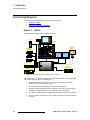
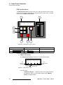
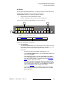
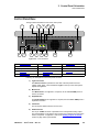
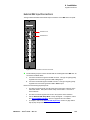
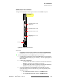
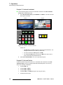
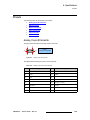
`çåíêçä=cÉ~íìêÉë
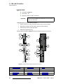
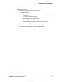
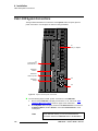
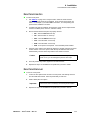
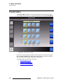
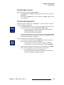
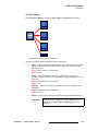
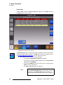
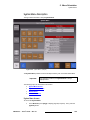
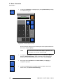
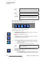
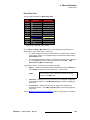
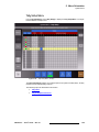
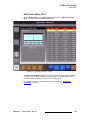
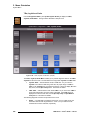
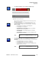
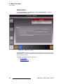
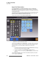
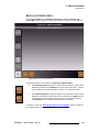
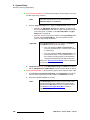
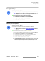
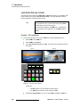
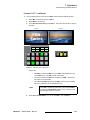
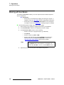
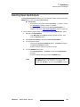
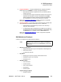
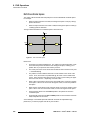
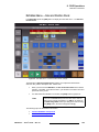
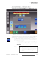
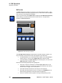
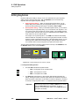
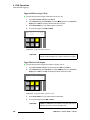
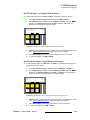
Two different control surfaces are available for the FSN Series:
•
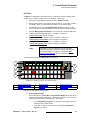
The FSN-150 is a 1.5 M/E production switcher providing 20 assignable
crosspoints (10 buttons plus SHIFT).
Figure 1-1. FSN-150 Control Panel
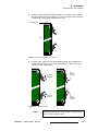
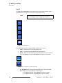
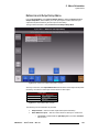
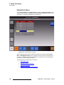
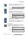
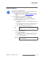
•
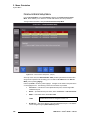
The FSN-250 is a 2.5 M/E production switcher providing 52 assignable
crosspoints (26 buttons plus SHIFT).
Figure 1-2. FSN-250 Control Panel
Additional control features are listed below:
•
•
A high-resolution color LCD touchscreen for setup and parameter adjustment.
•
Programmable LCD source labels for the switcher bus rows.
Programmable “custom” buttons, with LCD displays to indicate the current button
assignments.
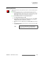
Note
24
The FSN-250 is not available in version 3.0.
FSN Series • User’s Guide • Rev 01
NK==fåíêçÇìÅíáçå
About the FSN Series
póëíÉã=`çåÑáÖìê~íáçå
The following topics are discussed in this section:
•
•
•
•
Basic FSN Series System
Required Cards
Optional Cards
M/E Features
_~ëáÅ=cpk=pÉêáÉë=póëíÉã
Because the FSN Series uses modular components, many flexible system configurations
can be designed to suit your exact production requirements. The basic system consists of
the following:
•
•
•
One FSN-150 control panel.
One FSN-1400 chassis.
One System Card and one Crosspoint M/E Card, both of which are required on
all systems. Refer to the “Required Cards” section below for details.
All other cards are optional, including the NIC, UIC, UOC, DVE, NAC and MVR. Refer to
the “Optional Cards” section on page 26 for details.
oÉèìáêÉÇ=`~êÇë
Required FSN Series cards are described below.
•
System Card — this required card includes:
~
~
~
~
~
Video reference input and loop through.
Configurable video reference output.
Ethernet port (10/100).
One tally connector (24 contact closures).
One GPIO connector (four GPI ports and eight GPO ports).
In Chapter 2, refer to the “System Card” section on page 44 for details.
•
Crosspoint M/E Card — This required card includes:
~
~
~
~
~
~
~
Crosspoint matrix.
M/E and PGM circuitry.
Dedicated DSK cut and fill inputs.
Six Aux outputs.
Four PGM outputs (PGM [2x], PVW and CLN).
Three M/E 1 outputs (PGM 1, PVW 1 and CLN 1).
Three M/E 2 outputs (PGM 2, PVW 2 and CLN 2).
In Chapter 2, refer to the “M/E Card” section on page 49 for details.
FSN Series • User’s Guide • Rev 01
25
NK==fåíêçÇìÅíáçå
About the FSN Series
léíáçå~ä=`~êÇë
Optional FSN Series cards are described below.
•
NIC (Native Input Card)
The NIC provides eight native video input channels, which run at the switcher's
selected native output resolution. In Chapter 2, refer to the “Native Input Card”
section on page 53 for details.
•
UIC (Universal Input Card)
The UIC provides two independent universal scaler channels, each of which is
used to scale input video to the switcher’s selected native output resolution. In
Chapter 2, refer to the “Universal Input Card” section on page 55 for details.
•
UOC (Universal Output Card)
The UOC provides two independent universal scaler output channels. Each card
can output scaled video and/or computer resolutions up to UXGA or 1920 x 1080,
or function as an additional native auxiliary output. In Chapter 2, refer to the
“Universal Output Card” section on page 58 for details.
•
DVE (Digital Video Effects)
The DVE card provides two internal 2-D DVE channels which can be used to
create PIPs, and fly PIPs and keys. In Chapter 2, refer to the “Digital Video
Effects Card” section on page 57 for details.
•
NAC (Native Aux Output Card)
The NAC provides eight auxiliary outputs which run at the system’s native
resolution. In Chapter 2, refer to the “Native Aux Output Card” section on
page 60 for details.
•
MVR (Multiviewer Card)
The MVR provides internal multiviewer capability, with the ability to display up to
16 source PIPs in both single and dual monitor configurations. In Chapter 2, refer
to the “Multiviewer Card” section on page 62 for details.
Important
In Chapter 2, refer to the “Card Slot Allocation and System
Flexibility” section on page 35 for details on maximum card
quantities and slot allocations in the FSN-1400 chassis.
jLb=cÉ~íìêÉë
Each M/E processor features the following capabilities:
•
•
•
A/B background mixer, plus two full function keyers
Pattern system (wipes)
PGM, PVW and assignable CLN outputs
Each PGM bank features the following:
•
•
•
•
•
26
A/B background mixer
Pattern system (wipes)
One downstream key (DSK)
Downstream FTB (Fade to Black)
PGM (2x), PVW and CLN outputs
FSN Series • User’s Guide • Rev 01
NK==fåíêçÇìÅíáçå
New Feature Review
kÉï=cÉ~íìêÉ=oÉîáÉï
The following topics are discussed in this section:
•
Version 3.0 Features
sÉêëáçå=PKM=cÉ~íìêÉë
This section lists the new hardware and software features that have been implemented in
the FSN Series version 3.0 release. Reference links are provided.
•
DVE Functionality
Version 3.0 supports the optional 2D DVE (Digital Video Effects) card, of which
two can be installed in FSN-1400 slots 9 and 10. DVE functionality includes:
~
~
~
~
~
Programming of single and dual keyframe DVE effects.
Ability to create PIPs, and fly PIPs and keys.
Joystick control of PIPs.
New DVE Assign Menu, accessed via the Setup Menu.
Full compliment of DVE programming menus, accessed via the {DVE}
button in the Menu Bar.
Refer to Chapter 8, “DVE Operations” on page 353 for details.
•
NAC Functionality
Version 3.0 supports up to three NACs (Native Aux Output Cards) in chassis slots
11, 12 and/or 13. Each NAC provides eight aux outputs which run at the system’s
native resolution. When installed, the associated Aux outputs are automatically
enabled on the control panel. In Chapter 2, refer to the “Native Aux Output
Card” section for details.
•
UOC Functionality
Version 2.0 supports up to three UOCs (Universal Output Cards) in slots 11, 12
and/or 13. Each UOC provides two independent universal scaler output channels.
In Chapter 2, refer to the “Universal Output Card” section for additional details.
•
MVR Functionality
Version 2.0 supports one MVR (Multiviewer Card) in slot 11. The MVR provides
internal multiviewer capability with the ability to display up to 16 source PIPs in
both single and dual monitor configurations. In Chapter 2, refer to the
“Multiviewer Card” section on page 62 for details.
Important
•
Regarding the NAC, UOC and MVR, refer to the “Card Slot
Allocation and System Flexibility” section for details on
maximum card quantities and slot allocations in the chassis.
Aux Menu
Version 2.0 activates the Aux Menu and the accompanying Aux Setup Menu.
Together, these menus enable you to set up, map, name and view all Aux buses.
In Chapter 5, refer to the “Aux Setup Menu” section for setup menu details, and
the “Aux Menu” section for operating details.
FSN Series • User’s Guide • Rev 01
27
NK==fåíêçÇìÅíáçå
New Feature Review
•
M/E 2 Control
Version 2.0 supports control of M/E 2 from the FSN-150. All M/E 2 outputs on the
FSN-1400 are active, a new M/E Setup Menu is provided, and the M/E 2 button
in the Memory Section is active. In Chapter 5, refer to the “Other Setup Menu”
section for setup details. In Chapter 7, refer to the “M/E 2 Control on the FSN150” section for M/E 2 operating instructions.
•
NIC Gamma Adjustment
Gamma adjustment has been added to all NIC (Native Input Card) inputs. The
adjustment range is 0.5 to 3.0, in .01 increments. In Chapter 5, refer to the “Input
Menu” section on page 202 for details.
•
Ancillary Data Support for SD Rates
For SD (standard definition) formats, for direct NIC-to-AUX output routes, ancillary
data present on NIC inputs is now preserved to SDI Aux outputs. However, if the
signal travels through an M/E, a UIC or the DVE, ancillary data is stripped. Please
note the following important points:
•
~
In Frame Sync mode, if a frame is repeated or dropped, the ancillary
data for that frame is also repeated or dropped.
~
For HD (high definition) video formats, the same rules apply.
Video Reference Output
On the Reference and Output Setup Menu, new features are provided:
~
Users can adjust the reference video output by toggling the {Reference
Out} button to either Black Burst or Tri-level Sync.
Important
~
This change activates the Ref Out BNC connector on the
System Card’s rear panel.
By pressing {Reference Output Timing}, users can adjust H and V
phase relative to video reference input.
Please note:
•
~
In Chapter 2, refer to the “System Card” section on page 44 for
information on the Ref Out connector.
~
The sync out format (as provided on the Ref Out BNC) changes,
depending on the selected native video format. In Appendix A, refer to
the “Reference Video Output Specifications” section on page 434 for
details on each format.
Additional Native Video Output Formats
Three new native video output formats have been added to the system:
~
~
~
1920 x 1080p @ 23.98
1920 x 1080p @ 24
1920 x 1080p @ 25
Please note:
28
~
Use the Reference and Output Setup Menu to select the desired native
output format. In Chapter 5, refer to the “Reference and Output Setup
Menu” section on page 197 for menu details.
~
In Appendix A, refer to the “Output Formats” section on page 449 for a
complete list of all available output formats.
FSN Series • User’s Guide • Rev 01
NK==fåíêçÇìÅíáçå
New Feature Review
•
Additional Test Pattern
The SMPTE RP-219 test pattern has been added to the Output Test Patterns
Menu.
•
Menu Enhancements
The following menus have been enhanced with new features:
•
~
Wipe Menu — In Chapter 5, refer to the “Wipe Menu” section on
page 151 for menu details.
~
Keyer Menu — In Chapter 5, refer to the “Keyer Menu” section on
page 157 for menu details.
Feature Enhancements
In the Memory Section on the FSN-150, pressing STORE now lights all active
buttons in the Module Section automatically. Module buttons toggle on/off in the
normal way. This enhancement enables you to easily store the “entire” switcher.
The RECALL procedure is identical to the previous version.
•
Analog Format Connection Table — Correction
In the Analog Format Connection Table on page 65, the Chroma connection for
the S-Video format has been corrected to indicate Blue, instead of Red.
FSN Series • User’s Guide • Rev 01
29
NK==fåíêçÇìÅíáçå
Connectivity Diagrams
`çååÉÅíáîáíó=aá~Öê~ãë
The following connectivity diagrams are provided in this section:
•
•
System 1 — Basic
System 2 — Multiple Destinations
póëíÉã=N=Ô=_~ëáÅ
The figure below illustrates a basic FSN Series system:
PC
FSN-150
Program
Screen
Cameras
Analog / Digital
Program
Preview
Ethernet
VTR / DVR
Aux 1
Program Record
Server
FSN-1400
Figure 1-3. Block diagram, basic FSN Series system (sample)
This configuration is an ideal basic setup consisting of multiple inputs, a single destination
output and a single Aux output. In the diagram:
30
•
Multiple scaled and un-scaled sources connect to the FSN-1400, including
cameras, PCs, VTRs, DVRs and servers.
•
•
The FSN-1400 and FSN-150 control panel connect via Ethernet.
•
•
The switcher’s SDI (SD-SDI or HD-SDI) Program output connects to the projector.
Program and Preview monitor outputs enable the TD to view the entire output of
the switcher, and preview the “look” that’s coming next on all outputs.
One Aux output is connected to a VTR, providing the ability to record the output of
the event.
FSN Series • User’s Guide • Rev 01
NK==fåíêçÇìÅíáçå
Connectivity Diagrams
póëíÉã=O=Ô=jìäíáéäÉ=aÉëíáå~íáçåë
The figure below illustrates a sample system in which individual Aux outputs are routed to
different destinations.
PC
Left
Screen
Center
Screen
Right
Screen
Aux 1
Aux 2
Aux 3
M/E 1
PGM
M/E 1
FSN-150
Program
Preview
Cameras
Analog / Digital
Ethernet
Aux 4
Aux 5
Green Room
Production
VTR / DVR
Aux 6
ISO Camera Record
Server
FSN-1400
Figure 1-4. Block diagram, multiple destination FSN Series system (sample)
This configuration is ideal for a setup consisting of three projected images behind a
podium. The left and right images are identical (as switched on M/E 1), and the center
image can be identical, or different from the two “wing” projectors (as switched on the PGM
bank). By connecting Aux outputs to different projectors, the TD has complete creative
control over the look, with the ability to display different setups on the projectors.
In the diagram:
•
Multiple scaled and un-scaled sources connect to the FSN-1400, including
cameras, PCs, VTRs, DVRs and servers.
•
•
•
The FSN-1400 and FSN-150 connect via Ethernet.
Aux outputs 1, 2 and 3 connect to the three projectors.
Aux outputs 4, 5 and 6 are connected to peripheral devices, such as monitors and
VTRs. In practice, this enables the TD to provide completely independent stage
or green room monitors, plus the ability to record the output of the entire event.
FSN Series • User’s Guide • Rev 01
31
NK==fåíêçÇìÅíáçå
Application Questions
^ééäáÅ~íáçå=nìÉëíáçåë
At Barco, we take pride in offering unique solutions to demanding technical problems. If
you have application questions, require further information or would like to discuss your
application requirements in more detail, please call (866) 469-8036. Our Customer
Support Engineers will be happy to supply you with the support you need. Refer to
Appendix B, “Contact Information” on page 451 for details.
32
FSN Series • User’s Guide • Rev 01
OK==cpkJNQMM=lêáÉåí~íáçå
få=qÜáë=`Ü~éíÉê
This chapter provides detailed explanations of the FSN-1400 chassis, including all front
and rear chassis cards.
The following topics are discussed:
•
•
•
•
Hardware Description
Card Descriptions
Card LEDs
Analog Format Connection Table
Note
FSN Series • User’s Guide • Rev 01
Once you have reviewed all of the sections in this chapter,
please continue with Chapter 3, “Control Panel Orientation”
on page 67.
33
2. FSN-1400 Orientation
Hardware Description
e~êÇï~êÉ=aÉëÅêáéíáçå
The following topics are discussed in this section:
•
•
•
•
•
Chassis Overview
Card Slot Allocation and System Flexibility
Chassis Front Door
Chassis Front
Chassis Rear
`Ü~ëëáë=lîÉêîáÉï
The FSN Series chassis (FSN-1400) permits a high degree of flexibility in terms of the
number of inputs and outputs that you can configure. Please note:
•
•
All cards are modular and hot-swappable.
The 6RU chassis supports:
~
~
14 rear slots, the configuration of which depends on the type (and
number) of populated front cards.
•
An internal “midplane” architecture allows cards to be plugged in from both the
front and rear of the chassis.
•
•
There are no active components on the midplane or on the plug-in rear panels.
•
The following additional features are provided:
The front door provides a seal for air flow and chassis cooling. There are no
controls on the door, but two status LEDs are provided. Refer to the “Chassis
Front Door” section on page 37 for details.
~
~
~
~
34
14 front cards, including required and optional cards.
Optional dual redundant hot-swappable power supplies.
One tally connector (24 contact closures).
One GPIO connector, with four input (GPI) and eight output (GPO) ports.
Two serial ports.
FSN Series • User’s Guide • Rev 01
2. FSN-1400 Orientation
Hardware Description
`~êÇ=päçí=^ääçÅ~íáçå=~åÇ=póëíÉã=cäÉñáÄáäáíó
Within the FSN-1400 chassis, two card slots are dedicated (System and M/E). The
allocation of the remaining slots is flexible, as illustrated in the following table.
Table 2-1. FSN Series chassis card slot allocations
Card Type
Max. # of Cards per Chassis
Slot Number(s)
System (Required card)
1
14
M/E (Required card)
1
8
NIC (Native Input Card), 8-channel
4
1 - 4 (default slot: 1)
UIC (Universal Input Card), 2-channel
5
3 - 7 (default slot: 7)
MVR (Multiviewer Card)
1
11
UOC (Universal Output Card), 2-channel
3
11, 12, 13 (default slot: 12)
NAC (Native Aux Output Card), 8-channel
3
11, 12, 13 (default slot: 13)
DVE (Digital Video Effects) card, 2-channel
2
9, 10
Because different combinations of cards can be installed in the FSN-1400 chassis, input
and output combinations are highly flexible. Refer to the following two sections for details:
•
•
Input Flexibility
Auxiliary Output Flexibility
Please note:
•
Refer to the “Chassis Front” section on page 39 and the “Chassis Rear” section
on page 41 for detailed information on all chassis card slots.
•
Refer to the “Card Descriptions” section on page 43 for in-depth information of
all cards and their capabilities.
fåéìí=cäÉñáÄáäáíó
The following table outlines the system’s input flexibility, based on the numbers of eight
channel NICs and two channel UICs that can be installed:
Table 2-2. FSN Series input flexibility
Total Inputs (Installed NICs + Installed UICs)
0 UIC
installed
1 UIC
installed
2 UICs
installed
3 UICs
installed
4 UICs
installed
5 UICs
installed
0 NIC installed
0
2
4
6
8
10
1 NIC installed
8
10
12
14
16
18
2 NICs installed
16
18
20
22
24
26
3 NICs installed
24
26
28
30
32
4 NICs installed
32
34
36
38
FSN Series • User’s Guide • Rev 01
35
2. FSN-1400 Orientation
Hardware Description
^ìñáäá~êó=lìíéìí=cäÉñáÄáäáíó
The following two tables outline the system’s auxiliary output flexibility, based on the
number of 2-channel UOC cards installed, the number of 8-channel NAC cards installed,
and whether or not the MVR is installed.
The totals listed below include the six standard native Aux outputs on the M/E card, plus
the number of outputs on the installed UOCs and NACs.
•
With no MVR (Multiviewer) installed in slot 11, three chassis slots (11, 12 and 13)
are available for Aux output cards. The following combinations of Aux outputs are
available:
Table 2-3. Auxiliary output flexibility - Multiviewer is not installed
Total Aux Outputs — Multiviewer Not Installed
0 NACs installed
1 NAC installed
2 NACs installed
3 NACs installed
0 UOCs installed
6
14
22
30
1 UOC installed
8
16
24
2 UOCs installed
10
18
3 UOCs installed
12
•
When the MVR is installed in slot 11, only two slots (12 and 13) are available for
Aux output cards. The following combinations of Aux outputs are available:
Table 2-4. Auxiliary output flexibility - Multiviewer is installed
Total Aux Outputs — Multiviewer Installed
0 NACs installed
1 NAC installed
2 NACs installed
0 UOCs installed
6
14
22
1 UOC installed
8
16
2 UOCs installed
10
Note that when additional Aux output cards are installed, use the Aux Setup Menu to map
Aux outputs to the control panel, and name Aux outputs (if desired). In Chapter 5, refer to
the “Aux Setup Menu” section on page 240 for details.
36
FSN Series • User’s Guide • Rev 01
2. FSN-1400 Orientation
Hardware Description
`Ü~ëëáë=cêçåí=aççê
The figure below illustrates a view of the chassis front door:
1
2
3
FSN-1400
Power
Video Reference
Figure 2-1. FSN Series chassis front door
1)
Door Latch
2)
System Status LEDs
3)
Hinges
Following are descriptions of each section.
1)
Door Latch
One latch is provided to facilitate door opening and closing. See the “Door
Removal and Re-installation” section on page 38 for instructions.
2)
System Status LEDs
The two System Status LEDs are mounted on the System Card, but they are
visible through the slot in the front door — via light pipe.
The Power LED indicates power status for the chassis and the system card.
~
~
~
Green = the system card has power and the card’s software is running.
Red = not used in version 3.0.
Off = one or more of the following conditions are present:
•
There is no power to the FSN-1400.
•
There is no System Card in the FSN-1400.
•
The System Card has failed.
FSN Series • User’s Guide • Rev 01
37
2. FSN-1400 Orientation
Hardware Description
The Video Reference LED indicates the status of the system’s analog video
reference input, via the Vid Ref connector on the System Card’s rear panel.
~
Green = the system is configured for External Reference, a video
reference signal is present and the FSN-1400 is locked to the signal.
~
Red = the system is configured for External Reference, the signal is
missing or the FSN-1400 is not locked to the signal.
~
Off = the system is configured for Free Run.
Note
3)
If the Power LED is off, the Video Reference LED will also
be off.
Hinges
Two hinges are provided on the right side of the door, to facilitate door removal
and re-installation. See the “Door Removal and Re-installation” section below
for door removal and installation instructions.
^áê=cáäíÉê
An air filter is located on the inside of the front door, in the bottom half of the door. Using
the four thumb nuts, this filter can be easily removed and cleaned periodically, as required.
aççê=oÉãçî~ä=~åÇ=oÉJáåëí~ää~íáçå
Use the following steps to open and remove the FSN-1400 front door:
1.
On the Latch, press inwards on the top label that reads “Push.”
2.
Lift the lower portion of the Latch that reads “Lift and Turn.”
3.
Turn the Latch clockwise, and open the door.
4.
To remove the door, lift it up and off of its hinges.
Use the following steps to re-install the FSN-1400 front door:
1.
Align the female hinges on the door with the male hinges on the FSN-1400.
2.
Set the door down on the hinges until it is fully seated.
3.
Close the door.
4.
Turn the Latch counter-clockwise, then push the Latch in to re-seat it.
Important
38
Operating the FSN-1400 without the door fully closed and the
filter installed will cause overheating and possible damage.
FSN Series • User’s Guide • Rev 01
2. FSN-1400 Orientation
Hardware Description
`Ü~ëëáë=cêçåí
The figure below illustrates a sample front view of a fully-loaded chassis (door removed):
1
2
WARNING: Operating the unit without the fan
tray will cause overheating and possible damage .
UNLOCK
Slot: 14
13
12
11
10
UNLOCK
9
8
7
6
5
4
3
2
1
Loaded
NIC
Power
Loaded
NIC
Native Input Card
Native Input Card
Universal Input Card
Power
UIC
Loaded
Loaded
Power
Loaded
UIC
Power
Universal Input Card
Universal Input Card
Universal Input Card
UIC
Power
Power
UIC
Loaded
Power
UIC
Loaded
Power
M/E
Loaded
Loaded
Power
Loaded
DVE
Universal Input Card
Mix / Effects Card
DVE Card
DVE Card
Multiviewer Card
DVE
Power
Loaded
Power
MVR
Loaded
Power
Loaded
UOC
RS-232
Power
NAC
Loaded
SYS
Power
System Card
AC OK
Universal Output Card
Native Aux Output Card
DC OK
DC OK
CPU
IP
AC OK
3
4
5
6
7
Figure 2-2. FSN Series chassis, front view (sample)
1)
Power Supplies
4)
Aux and MVR Card Slots
2)
Fan Tray
5)
DVE Card Slots
3)
System Card Slot
6)
M/E Card Slot
7)
Input Card Slots
Following are descriptions of each section. Note that slots are numbered from right to left,
to correlate with the associated rear slots.
1)
Power Supplies
Two slots are provided for dual redundant hot-swappable power supplies, each
with a 600W capability. Each supply has two LEDs:
~
DC OK LED:
•
Green = DC power (from the supply) is OK.
•
Red = DC power is bad or has failed.
~
AC OK LED:
•
Green = AC power (into the supply) is OK.
•
Red = AC power is bad or has failed.
FSN Series • User’s Guide • Rev 01
39
2. FSN-1400 Orientation
Hardware Description
2)
Fan Tray
For chassis cooling, one slot is provided for the required hot-swappable fan tray.
The integral handle enables the tray to be easily removed and installed.
Important
3)
The fan tray must be installed whenever power is applied to
the chassis. Operating the unit without the fan tray will cause
overheating and possible damage.
System Card Slot
Slot 14 is reserved for the required System Card. Refer to the “System Card”
section on page 44 for details.
4)
Aux and MVR Card Slots
Slots 11, 12 and 13 are reserved for three types of optional cards:
5)
~
UOC (Universal Output Card). Up to three cards can be installed. See
the “Universal Output Card” section on page 58.
~
NAC (Native Aux Output Card). Up to three cards can be installed. See
the “Native Aux Output Card” section on page 60.
~
MVR (Multiviewer Card). One card can be installed in slot 11 only. See
the “Multiviewer Card” section on page 62.
DVE Card Slots
Slots 9 and 10 are reserved for optional 2-D DVE (Digital Video Effects) cards. Up
to two cards can be installed. Refer to the “Digital Video Effects Card” section
on page 57 for details.
6)
M/E Card Slot
Slot 8 is reserved for the required M/E (Mix/Effects) card. Refer to the “M/E Card”
section on page 49 for details.
7)
Input Card Slots
Slots 1 through 7 are reserved two types of input cards:
40
~
NIC (Native Input Card). Up to four cards can be installed in slots 1
through 4. See the “Native Input Card” section on page 53 for details.
~
UIC (Universal Input Card). Up to five cards can be installed in slots 3
through 7. Refer to the “Universal Input Card” section on page 55 for
details.
FSN Series • User’s Guide • Rev 01
2. FSN-1400 Orientation
Hardware Description
`Ü~ëëáë=oÉ~ê
The figure below illustrates a rear view of the FSN Series chassis, with all slots fully loaded
with both required and optional panels:
1
Slot: 1
2
3
4
5
6
7
1
1
1
1
1
8
9
10
11
12
13
14
1
Analog
Analog
Analog
Analog
SDI
Analog
SDI
Analog
PGM
SDI
1
CLN
Fill
PGM
1
Serial 2
4
Ethernet
DVI Digital
4
PGM
M/E 2
DVI Digital
DVI Digital
DVI Digital
DVI Digital
DVI Digital
6
2
2
2
2
CLN
6
1
Loop
LTC Input
8
Ref Out
2
2
3
100 - 240 VAC
8A, 50 - 60 Hz x2
Ref In
2
Analog
5
2
2
6
7
PVW
Analog
Analog
8
Analog
7
GPIO
3
DVI Digital
AUX
5
Analog
8
Tally
2
2
5
Analog
7
SDI
SDI
M/E 1
SDI
SDI
4
CLN
6
Serial 1
3
PVW
5
DVI Digital
Cut
DVI Digital
DSK
DVI Digital
DVI Digital
DVI Digital
DVI Digital
PVW
3
SDI
4
2
SDI
3
1
DVI Digital
2
1
SDI
1
4
5
6
7
Figure 2-3. Sample FSN Series chassis, rear view
1)
Air Vents
4)
DVE (Blank) Panel
2)
Input Card Panels
5)
Aux and MVR Output Card Panels
3)
M/E Card Panel
6)
System Card Panel
7)
AC Power
In the descriptions below, slots are numbered from left to right:
1)
Air Vents
At the top of the chassis, Air Vents are provided to assist with cooling. Air flows
from the front of the chassis to the rear. To prevent overheating, do not block the
air vents.
2)
Input Card Panels
Slots 1 through 7 are reserved for two types of input card panels:
~
NIC panels. Up to four panels can be installed in slots 1 through 4. See
the “Native Input Card” section on page 53 for details.
FSN Series • User’s Guide • Rev 01
41
2. FSN-1400 Orientation
Hardware Description
~
3)
UIC panels. Up to five panels can be installed in slots 3 through 7. Refer
to the “Universal Input Card” section on page 55 for details.
M/E Card Panel
Slot 8 is reserved for the required M/E card panel. Refer to the “M/E Card”
section on page 49 for details.
4)
DVE (Blank) Panel
Slots 9 and 10 are reserved for blank panels, as the DVE card does not require
any connectors. See the “Digital Video Effects Card” section on page 57.
5)
Aux and MVR Output Card Panels
Slots 11, 12 and 13 are reserved for three types of optional cards:
6)
~
UOC (Universal Output Card). Up to three panels can be installed. See
the “Universal Output Card” section on page 58.
~
NAC (Native Aux Output Card). Up to three panels can be installed.
See the “Native Aux Output Card” section on page 60.
~
MVR (Multiviewer Card). One panel can be installed in slot 11 only. See
the “Multiviewer Card” section on page 62.
System Card Panel
Slot 14 is reserved for the System card panel. Refer to the “System Card”
section on page 44 for details.
7)
AC Power
The AC Power section provides two AC power connectors with integral switches.
One connector is provided for each supply, which allows the frame to be powered
from two different circuit breakers in a redundant configuration.
42
Note
The default FSN-1400 configuration has one power supply
installed in the lower slot. The bottom AC connector is used.
Important
Unused rear slots must have blank panels installed for
purposes of thermal management and EMI.
FSN Series • User’s Guide • Rev 01
2. FSN-1400 Orientation
Card Descriptions
`~êÇ=aÉëÅêáéíáçåë
The following required and optional cards are discussed in this section:
•
•
•
•
•
•
•
•
•
•
System Card
M/E Card
Native Input Card
Universal Input Card
Digital Video Effects Card
Universal Output Card
Native Aux Output Card
Multiviewer Card
Card LEDs
Analog Format Connection Table
Note
FSN Series • User’s Guide • Rev 01
On all following card descriptions, remember that all physical
connectors are located on the associated rear panels. Note
also that the DVE (Digital Video Effects) card does not have
any associated rear panel.
43
2. FSN-1400 Orientation
Card Descriptions
póëíÉã=`~êÇ
Card status: Required
Slot number: 14
Maximum number of cards per chassis: 1
Important
This card is pre-installed in the FSN-1400. Do not move the
card to any other slots.
The System Card provides the following functions:
•
•
•
•
System control, CPU, timing, and video reference (input, loop and output).
Ethernet port 10/100, two serial outputs, Tally (24 contact closures).
GPIO (four input ports, eight output ports).
RS-232 port (diagnostics only).
The figure below illustrates the System card’s front edge and rear panel connectors:
1
3
14
System Card
2
Serial 1
9
Tally
Power
4
Loaded
SYS
5
Serial 2
15
10
6
RS-232
Ethernet
GPIO
11
7
Ref In
CPU
12
IP
8
Loop
13
Ref Out
3
Front Edge
Rear Panel
Figure 2-4. System card front edge and rear panel connectors
1)
System Power LED
6)
Diagnostic Port
11)
Ref In
2)
Video Reference LED
7)
CPU Reset Switch
12)
Loop
3)
Ejectors
8)
IP Address Reset Switch
13)
Ref Out
4)
Card Power LED
9)
Serial Ports
14)
Tally Connector
5)
Loaded LED
10)
Ethernet Port
15)
GPIO Connector
44
FSN Series • User’s Guide • Rev 01
2. FSN-1400 Orientation
Card Descriptions
Following are descriptions of all components on the front edge of the System card:
1)
System Power LED
The System Power LED indicates power status for the chassis and the cards.
~
~
Green = all system power is OK.
~
Off = one or more of the following conditions are present:
•
The chassis is turned off.
•
DC output from all power supplies is bad or has failed.
•
Power has failed on the System Card.
Red = one or more of the following conditions are present:
•
DC output from one (of the two) chassis power supplies is bad
or has failed.
•
Power is bad (or has failed) on one or more of the installed
circuit cards.
Note that this LED is carried through to the front door via light pipe.
2)
Video Reference LED
The Video Reference LED indicates the status of the system’s analog video
reference input, via the Vid Ref connector on the System Card’s rear panel.
~
Green = the system is configured for External Reference, a video
reference signal is present and the FSN-1400 is locked to the signal.
~
Red = the system is configured for External Reference, the signal is
missing or the FSN-1400 is not locked to the signal.
~
Off = the system is configured for Free Run.
Note
If the Power LED is off, the Video Reference LED will also
be off.
Note that this LED is carried through to the front door via light pipe.
3)
Ejectors
Use the card’s top and bottom Ejectors to remove (and re-insert) the card.
4)
Card Power LED
The Card Power LED indicates power status for the card. Refer to the “Card
LEDs” section on page 64 for details.
5)
Loaded LED
The Loaded LED indicates the status of all FPGAs on the card. Refer to the
“Card LEDs” section on page 64 for details.
6)
Diagnostic Port
One RS-232 port is provided for diagnostics. This port is not available to the user.
7)
CPU Reset Switch
Using a small tool such as a paper clip, press the CPU Reset Switch to perform a
soft system reset. This function reboots the system, but preserves all setups and
memory registers, and maintains all crosspoint selections on the control panel.
Please note:
~
This is the same as pressing {Soft Reset System} on the Reset Menu.
In Chapter 5, refer to the “Reset Menu” section on page 274 for details.
FSN Series • User’s Guide • Rev 01
45
2. FSN-1400 Orientation
Card Descriptions
8)
IP Address Reset Switch
Using a small tool such as a paper clip, press the IP Address Reset Switch for 5
(five) seconds. This action resets the chassis IP address to the default value of
192.168.0.4, and then performs a factory reset. Please note:
~
This is the same as pressing {Factory Reset} on the Reset Menu. In
Chapter 5, refer to the “Reset Menu” section on page 274 for details.
~
Use the Com Setup Menu to change the IP address if required. In
Chapter 6, refer to the “Communications Setup” section on page 285
for details.
Following are descriptions of all components on the System card’s rear panel:
9)
Serial Ports
Two DB-9 connectors are provided for Serial connections. In Appendix A, refer to
the “Serial Connectors” section on page 442 for details.
Note
This function is currently not implemented.
10) Ethernet Port
One RJ-45 connector is provided for a 10/100 Ethernet connection between the
FSN Series control panel and the FSN-1400. For multiple Ethernet connections,
an Ethernet switch is recommended. There are two LEDs on the connector:
Link Speed
Link/Activity
Figure 2-5. Ethernet Connector
~
When a valid link is present, the amber Link Speed LED indicates
100mb Ethernet speed when lit, and 10mb speed when off.
~
The green Link/Activity LED indicates that a link is present when lit, and
link activity when blinking.
Please note:
~
In Appendix A, refer to the “Ethernet Connector” section on page 441
for Ethernet connector pinout details.
~
Use the Com Setup Menu to change the chassis’ IP address. In
Chapter 6, refer to the “Communications Setup” section on page 285
for details.
~
Refer to the “FSN Series Ethernet Connections” section on page 48 for
more information about Ethernet.
11) Ref In
One BNC is provided for an analog Reference Input connection. Accepted video
reference signals are black burst, SMPTE bi-level sync and tri-level sync.
Note
46
In Appendix A, refer to the “Reference Video Input
Specifications” section on page 433 for detailed information
about the allowed frame rates for the reference input.
FSN Series • User’s Guide • Rev 01
2. FSN-1400 Orientation
Card Descriptions
12) Loop
One BNC connector is provided for a reference Loop connection, which enables
you to loop the incoming reference signal to the next device in your system. If the
reference Loop is not used, connect a 75 ohm terminator to the connector.
13) Ref Out
One BNC connector is provided for a Reference Output signal. Using the
{Reference Out} button on the Reference and Output Setup Menu, this output
can be toggled between Tri-Level Sync and Black Burst.
Important
The sync out format (as provided on the connector) changes,
depending on the selected native video format. In
Appendix A, refer to the “Reference Video Output
Specifications” section on page 434 for details.
14) Tally Connector
One DB-50 connector is provided for tally, with 24 contact closures available. In
Appendix A, refer to the “Tally Connector” section on page 443 for pinouts. In
Chapter 6, refer to the “Tally Setup” section on page 303 for setup details.
15) GPIO Connector
One DB-25 connector is provided for GPIO, with four input ports and eight output
ports. In Appendix A, refer to the “GPIO Connector” section on page 444.
Note
FSN Series • User’s Guide • Rev 01
This function is currently not implemented.
47
2. FSN-1400 Orientation
Card Descriptions
cpk=pÉêáÉë=bíÜÉêåÉí=`çååÉÅíáçåë
This section provides information on all FSN Series Ethernet connections.
Switch
Ethernet Port 1
Ethernet
FSN-1400
FSN-150
Figure 2-6. Basic system Ethernet diagram
•
FSN-1400
The FSN-1400 has a single Ethernet port located on the System card. This port
connects to Ethernet Port 1 on the FSN-150 or FSN-250 control panel, either
directly or via an Ethernet switch. By default, the following conditions are set:
~
~
~
DHCP = OFF
Default IP address: 192.168.0.4
Default Netmask: 255.255.255.0
The user can use the default address, or set a different address.
•
FSN-150 and FSN-250 control panels
Each control panel has two Ethernet ports located on the rear panel:
~
Ethernet Port 1 connects to the FSN-1400, either directly or via an
Ethernet Switch. By default, the following conditions are set:
•
DHCP = OFF
•
Default IP address: 192.168.0.5
•
Default Netmask: 255.255.255.0
The user can use the default address, or set a different address.
~
Ethernet Port 2 can be connected to an outside network, or to your
facility’s “house” network. By default, the following conditions are set:
•
DHCP = ON
An IP address can be obtained automatically from the outside network.
Use the Com Setup Menu to change IP addresses. In Chapter 6, refer to the
“Communications Setup” section on page 285 for details.
48
FSN Series • User’s Guide • Rev 01
2. FSN-1400 Orientation
Card Descriptions
jLb=`~êÇ
Card status: Required
Slot number: 8
Maximum number of cards per chassis: 1
Important
This card is pre-installed in the FSN-1400. Do not move.
The M/E (Mix/Effects) Card provides the following functions:
•
•
•
Dedicated DSK cut and fill inputs. These must be locked to video reference.
•
All outputs run at the system's native video format.
Four PGM/PVW outputs (PGM [2x], PVW and CLN).
Three M/E 1 outputs (PGM, PVW, CLN), three M/E 2 outputs (PGM, PVW, CLN),
six native Aux outputs.
The figure below illustrates the M/E card’s front edge and rear panel connectors:
1
PGM
Mix / Effects Card
DSK
PVW
Cut
14
6
CLN
Fill
PGM
1
7
M/E 1
3
Loaded
Power
13
5
M/E
2
4
4
8
2
PVW
AUX
9
CLN
3
15
10
4
M/E 2
PGM
11
PVW
5
CLN
6
12
1
Front Edge
Rear Panel
Figure 2-7. M/E card front edge and rear panel connectors
1)
Ejectors
6)
Clean Feed Out
11)
M/E 2 Preview Out
2)
Card Power LED
7)
M/E 1 Program Out
12)
M/E 2 Clean Feed Out
3)
Loaded LED
8)
M/E 1 Preview Out
13)
DSK Cut In
4)
Program Out
9)
M/E 1 Clean Feed Out
14)
DSK Fill in
5)
Preview Out
10)
M/E 2 Program Out
15)
Native Aux Outputs
FSN Series • User’s Guide • Rev 01
49
2. FSN-1400 Orientation
Card Descriptions
Following are descriptions of all M/E card components:
1)
Ejectors
Use the card’s top and bottom Ejectors to remove (and re-insert) the card.
2)
Card Power LED
The Card Power LED indicates power status for the card. Refer to the “Card
LEDs” section on page 64 for details.
3)
Loaded LED
The Loaded LED indicates the status of all FPGAs on the card. Refer to the
“Card LEDs” section on page 64 for details.
4)
Program Out
Two BNC connectors are provided for the system’s main Program Output. Each
output is identical.
5)
Preview Out
One BNC is provided for the system’s main Preview Output. This output
provides the Program bank’s “lookahead” preview output. In Chapter 7, refer to
the “Understanding Lookahead Preview” section on page 319 for information.
6)
Clean Feed Out
One BNC is provided for the system’s main Clean Feed Output. Refer to the
“Clean Feed Output Selection” section on page 52 for details.
7)
M/E 1 Program Out
One BNC is provided for the system’s M/E 1 Program Output.
8)
M/E 1 Preview Out
One BNC is provided for the system’s M/E 1 Preview Output. This output
provides M/E 1’s “lookahead” preview output. In Chapter 7, refer to the
“Understanding Lookahead Preview” section on page 319 for information.
9)
M/E 1 Clean Feed Out
One BNC is provided for the system’s M/E 1 Clean Feed Output. Refer to the
“Clean Feed Output Selection” section on page 52 for details.
10) M/E 2 Program Out
One BNC is provided for the system’s M/E 2 Program Output.
11) M/E 2 Preview Out
One BNC is provided for the system’s M/E 2 Preview Output. This output
provides M/E 2’s “lookahead” preview output. In Chapter 7, refer to the
“Understanding Lookahead Preview” section on page 319 for information about
lookahead preview.
Note
On the FSN-150, M/E 2 control must be enabled to fully utilize
these outputs. In Chapter 7, refer to the “M/E 2 Control on
the FSN-150” section on page 349 for details.
12) M/E 2 Clean Feed Out
One BNC is provided for the system’s M/E 2 Clean Feed Output. Refer to the
“Clean Feed Output Selection” section on page 52 for details.
50
FSN Series • User’s Guide • Rev 01
2. FSN-1400 Orientation
Card Descriptions
13) DSK Cut In
One BNC is provided for a dedicated DSK Cut Input. The DSK Cut and DSK Fill
inputs must be locked to the FSN-1400 video reference within ± 0.5 lines, when
the {Output V-Lock} button is turned off (on the Reference and Output Setup
Menu). See the DSK Fill In description below for an important note.
14) DSK Fill in
One BNC is provided for a dedicated DSK Fill Input. The DSK Cut and DSK Fill
inputs must be locked to the FSN-1400 video reference within ± 0.5 lines, when
the {Output V-Lock} button is turned off.
Important
When the {Output V-Lock} button is turned on (on the
Reference and Output Setup Menu), the position of the
DSK Cut and DSK Fill inputs on screen will change.
•
If the user preference “Black on Invalid Video” is
turned on, the DSK turns off — because of the change
in output timing.
•
If the user preference “Black on Invalid Video” is off,
the DSK will be visible — but in a shifted position. In
this condition, the video position can be adjusted by
changing the output timing of the DSK source itself.
In Chapter 5, refer to the “User Preferences Menu” section
on page 254 for details on the Black on Invalid Video mode.
15) Native Aux Outputs
Six BNCs are provided for the system’s six Native Aux Outputs. Source
selection is performed in the Aux Assign Section on the panel. In Chapter 3,
refer to the “Aux Section” heading on page 71 for details.
FSN Series • User’s Guide • Rev 01
51
2. FSN-1400 Orientation
Card Descriptions
`äÉ~å=cÉÉÇ=lìíéìí=pÉäÉÅíáçå
The FSN-1400 provides three Clean Feed Outputs, one each for the PGM, M/E 1 and M/E
2 banks. Each output has selectable points from which the clean feed signal can be
picked, as illustrated in the following diagram.
M/E 1
KEY 1
Mixer
1
M/E 2
2
KEY 1
Mixer
4
PGM
KEY 2
3
M/E 2 Clean Feed Out
KEY 2
5
DSK
Mixer
M/E 1 Clean Feed Out
6
PGM Clean Feed Out
FTB
7
8
Figure 2-8. Clean Feed Output selections
The table below describes each output in detail.
Table 2-5. Clean Feed Output descriptions
Output
Description
1
M/E 1 clean out — pre KEY 1
2
M/E 1 clean out — pre KEY 2
3
M/E 1 out — post KEY 2
4
M/E 2 clean out — pre KEY 1
5
M/E 2 clean out — pre KEY 2
6
M/E 2 out — post KEY 2
7
Program clean out — pre DSK
8
Program out — Post FTB
In Chapter 7, refer to the “Selecting Clean Feed Outputs” section on page 347 for details
on using the Clean Feed Assignment Menu.
52
FSN Series • User’s Guide • Rev 01
2. FSN-1400 Orientation
Card Descriptions
k~íáîÉ=fåéìí=`~êÇ
Card status: Optional
Installs in slots: 1 - 4
Default slot: 1
Maximum number of cards per chassis: 4
The NIC (Native Input Card) is an eight-channel input card that provides the following:
•
•
•
•
Eight native resolution video inputs (BNC).
Frame synchronization for sources that are not locked to reference.
+/- 0.5 line auto-timing for input sources that are locked to video reference.
HD-SDI and SD-SDI capability.
Refer to the “Card Slot Allocation and System Flexibility” section on page 35 for details
on NIC configurations in the FSN-1400.
The figure below illustrates the NIC’s front edge and rear panel connectors:
1
Native Input Card
SDI
1
2
Power
2
Loaded
NIC
3
3
4
4
5
6
7
8
1
Front Edge
Rear Panel
Figure 2-9. NIC front edge and rear panel connectors
1)
Ejectors
3)
Loaded LED
2)
Card Power LED
4)
Native Inputs 1 - 8
Following are descriptions of all NIC components:
1)
Ejectors
Use the card’s top and bottom Ejectors to remove (and re-insert) the card.
FSN Series • User’s Guide • Rev 01
53
2. FSN-1400 Orientation
Card Descriptions
2)
Card Power LED
The Card Power LED indicates power status for the card. Refer to the “Card
LEDs” section on page 64 for details.
3)
Loaded LED
The Loaded LED indicates the status of all FPGAs on the card. Refer to the
“Card LEDs” section on page 64 for details.
4)
Native Inputs 1 - 8
Eight BNC connectors are provided for Native Inputs 1 - 8, and each connector
supports HD-SDI and SD-SDI sources. The video standard of all connections to
the NIC must be the same as the FSN-1400’s native output resolution.
Note
54
In Appendix A, refer to the “Delay Specifications” section on
page 438 for details on NIC delay.
FSN Series • User’s Guide • Rev 01
2. FSN-1400 Orientation
Card Descriptions
råáîÉêë~ä=fåéìí=`~êÇ
Card status: Optional
Installs in slots: 3 - 7
Default slot: 7
Maximum number of cards per chassis: 5
The UIC (Universal Input Card) is a two-channel card that scales non-native inputs (up to
UXGA or 1920 x 1080) to the switcher's native resolution and timing. One UIC provides
two universal scaled video inputs, plus additional capabilities for native resolution sources:
•
•
Frame synchronization for sources not locked to video reference.
For SDI inputs that match the native format, +/- 0.5 line auto-timing for input
sources that are locked to video reference.
Refer to the “Card Slot Allocation and System Flexibility” section on page 35 for details
on UIC configurations in the FSN-1400.
The figure below illustrates the UIC’s front edge and rear panel connectors:
1
DVI Digital
Universal Input Card
Analog
1
4
3
5
Analog
DVI Digital
SDI
Power
2
Loaded
UIC
1
2
Front Edge
Rear Panel
Figure 2-10. UIC front edge and rear panel connectors
1)
Ejectors
3)
Loaded LED
2)
Card Power LED
4)
Universal Input 1
5)
Universal Input 2
Following are descriptions of all UIC components:
1)
Ejectors
Use the card’s top and bottom Ejectors to remove (and re-insert) the card.
FSN Series • User’s Guide • Rev 01
55
2. FSN-1400 Orientation
Card Descriptions
2)
Card Power LED
The Card Power LED indicates power status for the card. Refer to the “Card
LEDs” section on page 64 for details.
3)
Loaded LED
The Loaded LED indicates the status of all FPGAs on the card. Refer to the
“Card LEDs” section on page 64 for details.
4)
Universal Input 1
Three connectors are provided for Universal Input 1 (1 x HD15, 1 x DVI-I, 1 x
BNC). Using these connectors, different combinations of inputs can be connected
to the FSN-1400, as outlined below, but only one of the three connectors can be
used at a time on the control panel.
Cells with check marks denote the connections required for the indicated format.
Table 2-6. UIC connector combinations for selected universal input formats
Connectors
Format
BNC
DVI-I
HD-15
HD-SDI
SD-SDI
DVI *
CVBS
Y/C
YPbPr **
RGsB
RGBS
RGBHV ***
* up to 165 MHz
** NTSC, PAL or HD
*** up to 165 MHz (UXGA)
Please note the following important points regarding the UIC:
~
5)
Refer to the “Analog Format Connection Table” section on page 65 for
additional information on using the HD-15 connector.
Universal Input 2
Input connections for Universal Input 2 are identical to Universal Input 1. Refer
to the explanation of Universal Input 1 for details.
Note
56
In Appendix A, refer to the “Delay Specifications” section on
page 438 for details on UIC delay.
FSN Series • User’s Guide • Rev 01
2. FSN-1400 Orientation
Card Descriptions
aáÖáí~ä=sáÇÉç=bÑÑÉÅíë=`~êÇ
Card status: Optional
Installs in slots: 9, 10
Maximum number of cards per chassis: 2
The DVE (Digital Video Effects) card is an optional 2-D two-channel scaler card. When one
or two DVE cards are installed, the DVE Assign Menu enables you to assign DVE
channels to any keyer on the control panel. Then, using the DVE Menu, you can create
single keyframe and two keyframe DVE effects.
The following rules apply:
•
•
•
One DVE card provides two internal DVE channels.
Two DVE cards provide four available internal DVE channels.
DVE channels can be assigned to a keyer’s “cut” and/or “fill” inputs. This feature
provides a great deal of flexibility. For example:
~
To “fly” a PIP or a luma key, one DVE channel is required. Assign a DVE
channel to the desired keyer’s “cut” signal.
~
To “fly” a linear key, two DVE channels are required. Assign DVE
channels to the desired keyer’s “cut” and “fill” signals.
~
To “fly” a split key, either one or two DVE channels are required
(depending on the effect you want to create). Assign channels to the
desired keyer’s “cut” and/or “fill” signals.
Please note:
•
A rear panel is not required with the DVE card — a blank panel is installed
instead.
•
Because DVE channels are assigned to specific keyers, input selection for the
channels is performed on the keyer’s associated key bus — in the same way that
key sources are selected.
•
LEDs on the DVE card’s front edge provide power and FPGA status. Refer to the
“Card LEDs” section on page 64 for details.
Refer to the “Card Slot Allocation and System Flexibility” section on page 35 for details
on DVE card configurations in the FSN-1400. Refer to Chapter 8, “DVE Operations,” for
complete information on DVE assignment, DVE menus and operations.
FSN Series • User’s Guide • Rev 01
57
2. FSN-1400 Orientation
Card Descriptions
råáîÉêë~ä=lìíéìí=`~êÇ
Card status: Optional
Installs in slots: 11, 12, 13
Default slot: 12
Maximum number of cards per chassis: 3
The UOC (Universal Output Card) is an optional two-channel scaler card that creates
scaled video and/or computer Aux outputs up to UXGA or 1920 x 1080. Users can set the
output resolution to be different from (or the same as) the system’s native resolution.
When UOCs are installed, use the Aux Setup Menu to map Aux outputs to the control
panel, and name Aux outputs (if desired). Refer to the “Card Slot Allocation and System
Flexibility” section on page 35 for details on UOC configurations in the FSN-1400.
The figure below illustrates the UOC’s front edge and rear panel connectors:
1
DVI Digital
Analog
Universal Output Card
1
UOC
5
Analog
DVI Digital
SDI
Power
3
Loaded
2
4
1
2
Front Edge
Rear Panel
Figure 2-11. UOC front edge and rear panel connectors
1)
Ejectors
3)
Loaded LED
2)
Card Power LED
4)
Universal Output 1
5)
Universal Output 2
Following are descriptions of all UOC components:
1)
Ejectors
Use the card’s top and bottom Ejectors to remove (and re-insert) the card.
2)
Card Power LED
The Card Power LED indicates power status for the card. Refer to the “Card
LEDs” section on page 64 for details.
58
FSN Series • User’s Guide • Rev 01
2. FSN-1400 Orientation
Card Descriptions
3)
Loaded LED
The Loaded LED indicates the status of all FPGAs on the card. Refer to the
“Card LEDs” section on page 64 for details.
4)
Universal Output 1
Three connectors are provided for Universal Output 1:
~
~
~
1 x HD15
1 x DVI-I
1 x BNC
Using these connectors, different combinations of outputs can be connected to
the FSN-1400, as outlined below.
Note
Multiple outputs on a single UOC channel can be active at the
same time, provided that the selected format is compatible.
For example, 1920 x 1080i @ 59.94 is a compatible format on
all three output connectors.
Cells with check marks denote the connections required for the indicated format.
Table 2-7. UOC connector combinations for selected universal output formats
Connectors
Format
BNC
DVI-I
HD-15
HD-SDI
SD-SDI
DVI *
CVBS
Y/C
YPbPr **
RGsB
RGBS
RGBHV ***
* up to 165 MHz
** NTSC, PAL or HD
*** up to 165 MHz (UXGA)
Refer to the “Analog Format Connection Table” section on page 65 for
additional information on using the HD-15 connector.
5)
Universal Output 2
Output connections for Universal Output 2 are identical to Universal Output 1.
Refer to the explanation of Universal Output 1 for details.
Note that test patterns can be assigned to any UOC output, and a raster box can be turned
on or off. In Chapter 5, see the “Output Test Patterns Menu” section for details.
FSN Series • User’s Guide • Rev 01
59
2. FSN-1400 Orientation
Card Descriptions
k~íáîÉ=^ìñ=lìíéìí=`~êÇ
Card status: Optional
Installs in slots: 11, 12, 13
Default slot: 13
Maximum number of cards per chassis: 3
The NAC (Native Aux Output Card) is an optional card that provides eight additional
auxiliary outputs that run at the system’s native resolution. When NACs are installed, use
the Aux Setup Menu to map Aux outputs to the control panel, and name Aux outputs (if
desired). Refer to the “Card Slot Allocation and System Flexibility” section on page 35
for details on NAC configurations.
The following additional features are provided on the NAC:
•
Aux outputs switch to black on LOS (loss of signal). In Chapter 7, refer to the
“Understanding Error Messages” section on page 316 for more details.
•
Aux outputs preserve ancillary data from NIC inputs. In Chapter 1, refer to the
“New Feature Review” section on page 27 for details.
•
Test patterns can be assigned to any NAC output, and a raster box can be turned
on or off. In Chapter 5, see the “Output Test Patterns Menu” section for details.
The figure below illustrates the NAC’s front edge and rear panel connectors:
Native Aux Output Card
1
SDI
1
2
Power
2
Loaded
NAC
3
3
4
4
5
6
7
8
1
Front Edge
Rear Panel
Figure 2-12. NAC front edge and rear panel connectors
60
1)
Ejectors
3)
Loaded LED
2)
Card Power LED
4)
Native Aux Outputs
FSN Series • User’s Guide • Rev 01
2. FSN-1400 Orientation
Card Descriptions
Following are descriptions of all NAC components:
1)
Ejectors
Use the card’s top and bottom Ejectors to remove (and re-insert) the card.
2)
Card Power LED
The Card Power LED indicates power status for the card. Refer to the “Card
LEDs” section on page 64 for details.
3)
Loaded LED
The Loaded LED indicates the status of all FPGAs on the card. Refer to the
“Card LEDs” section on page 64 for details.
4)
Native Aux Outputs
Eight BNC connectors are provided for the optional Native Aux Outputs.
FSN Series • User’s Guide • Rev 01
61
2. FSN-1400 Orientation
Card Descriptions
jìäíáîáÉïÉê=`~êÇ
Card status: Optional
Installs in slot: 11
Maximum number of cards per chassis: 1
The MVR (Multiviewer) is an optional card that provides the ability to display up to 16
source PIPs in both single and dual monitor configurations. With the desired monitor(s)
connected to the card, users can set the MVR’s output resolution, and select from a variety
of pre-defined multiviewer layouts.
The figure below illustrates the MVR’s front edge and rear panel connectors:
Multiviewer Card
1
DVI Digital
1
MVR
DVI Digital
SDI
Power
4
3
Loaded
2
5
LTC Input
2
1
Front Edge
6
Rear Panel
Figure 2-13. MVR front edge and rear panel connectors
1)
Ejectors
3)
Loaded LED
5)
MVR Output 2
2)
Card Power LED
4)
MVR Output 1
6)
LTC Input
Following are descriptions of all MVR components:
1)
Ejectors
Use the card’s top and bottom Ejectors to remove (and re-insert) the card.
2)
Card Power LED
The Card Power LED indicates power status for the card. Refer to the “Card
LEDs” section on page 64 for details.
3)
Loaded LED
The Loaded LED indicates the status of all FPGAs on the card. Refer to the
“Card LEDs” section on page 64 for details.
62
FSN Series • User’s Guide • Rev 01
2. FSN-1400 Orientation
Card Descriptions
4)
MVR Output 1
In order to provide multiviewer connections to both SDI and DVI compatible
monitors, two connectors are provided for MVR Output 1:
~
~
1 x DVI-I
1 x BNC
The same output signal appears on both the DVI-I and BNC connectors. MVR
Output 1 can be used in both single and dual multiviewer monitor configurations,
as selected on the Multiviewer Setup Menu:
~
In a single monitor layouts, the selected layout appears identically on
MVR Output 1 and MVR Output 2.
~
In a dual monitor layouts, one half of the selected layout appears on
MVR Output 1, and the other half appears on MVR Output 2.
Please note:
5)
~
The output resolution for both MVR outputs is set on the Multiviewer
Output Setup Menu, using the Output Format Keypad.
~
Both the BNC and DVI-I connectors can be active at the same time,
provided that the selected format is compatible. The valid combinations
are fully listed in the Output Format Keypad.
~
Refer to Chapter 9, “Multiviewer Operations” on page 411 for full
multiviewer setup details.
MVR Output 2
Output connections for MVR Output 2 are identical to MVR Output 1. See above
for details.
6)
LTC Input
One Phoenix connector is provided for the Multiviewer’s LTC (Longitudinal Time
Code) Input.
Figure 2-14. LTC Input connector
Two types of time code connections are possible:
~
~
For a differential connection, use the +, – and GND terminals.
For a single-ended connection, use the + and GND terminals.
Please note:
•
Test patterns can be assigned to any MVR output, and a raster box can be turned
on or off. In Chapter 5, see the “Output Test Patterns Menu” section for details.
FSN Series • User’s Guide • Rev 01
63
2. FSN-1400 Orientation
Card LEDs
`~êÇ=ibaë
On the front edge of all cards, two LEDs indicate the card’s FPGA and power status.
An FPGA (field-programmable gate array) is a semiconductor
device that can be configured by the engineer after
manufacturing — hence the name "field-programmable.”
Loaded
1
Power
Note
2
Figure 2-15. Card front edge LEDs
1)
Card Power LED
2)
Loaded LED
Following are descriptions of the two LEDs:
1)
Card Power LED
The Card Power LED indicates power status for the card.
~
~
~
2)
Green = card power is OK.
Red = power is bad (or has failed) on the card.
Off = the chassis is turned off or power has failed.
Loaded LED
The Loaded LED indicates the status of all FPGAs on the card.
~
~
~
64
Green = all FPGAs are loaded successfully.
Red = an FPGA is bad, or software has not properly loaded.
Off = the chassis is turned off or power has failed.
FSN Series • User’s Guide • Rev 01
2. FSN-1400 Orientation
Analog Format Connection Table
^å~äçÖ=cçêã~í=`çååÉÅíáçå=q~ÄäÉ
Each HD-15 analog connector on both the UIC and UOC enables you to input (or output) a
variety of video formats — including VGA, composite video, S-Video and YUV component
video.
•
•
For RGB with H and V sync, use the HD-15 connector directly.
Using a customer supplied HD-15 to 5 x BNC breakout cable, many combinations
are possible. Cells with check marks denote the connections required for the
indicated format.
Table 2-1. Analog Input and Output Combinations using Breakout Cable
Breakout Cable
Wire Color
Composite
Video
S-Video
(Y/C)
R
YUV
(YPbPr)
RGB
Sync on Green
RGB
Comp Sync
RGB
Separate H V
(Pr)
G
(Lum)
(Lum)
B
(Chroma)
(Pb)
H Sync
V Sync
FSN Series • User’s Guide • Rev 01
65
2. FSN-1400 Orientation
Analog Format Connection Table
66
FSN Series • User’s Guide • Rev 01
PK==`çåíêçä=m~åÉä=lêáÉåí~íáçå
få=qÜáë=`Ü~éíÉê
This chapter provides a detailed explanation of the FSN-150 control panel. The following
topics are discussed:
•
•
•
•
Control Panel Descriptions
Control Panel Rear
Control Panel Bottom
Touch Screen Connector Panel
Note
FSN Series • User’s Guide • Rev 01
Once you have reviewed all of the sections in this chapter,
please continue with Chapter 4, “Installation” on page 103.
67
3. Control Panel Orientation
Control Panel Descriptions
`çåíêçä=m~åÉä=aÉëÅêáéíáçåë
The following topics are discussed in this section:
•
•
•
FSN-150 Overview
FSN-150 Control Panel Sections
Functional Control Panel Sections
cpkJNRM=lîÉêîáÉï
The figures below provide simplified block diagrams of video flow through the FSN-1400,
as controlled by the FSN-150. Because M/E 2 control can be enabled or disabled from the
panel, two “flow” configurations are available:
•
The figure below illustrates video flow with M/E 2 control disabled:
Native and Scaled Inputs
Re-Entry
M/E 1 CLN
(Assignable)
Mixer
M/E 1
KEY 1
KEY 2
PGM CLN
(Assignable)
Mixer
PGM
M/E 1 Program Out
M/E 1 Preview Out
DSK
FTB
Program Out
Preview Out
Figure 3-1. Video flow, M/E 2 control disabled
•
The figure below illustrates video flow with M/E 2 control enabled:
Native and Scaled Inputs
Re-Entry
M/E 1 CLN
(Assignable)
Mixer
M/E 1
KEY 1
KEY 2
M/E 2 CLN
(Assignable)
Mixer
M/E 2
KEY 1
KEY 2
M/E 2 Program Out
M/E 2 Preview Out
PGM CLN
(Assignable)
Mixer
PGM
M/E 1 Program Out
M/E 1 Preview Out
DSK
FTB
Program Out
Preview Out
Figure 3-2. Video flow, M/E 2 control enabled
Note
68
When M/E 2 control is enabled on the FSN-150, the buttons
on M/E 1 temporarily become the buttons for M/E 2. In
Chapter 7, refer to the “M/E 2 Control on the FSN-150”
section on page 349 for details.
FSN Series • User’s Guide • Rev 01
3. Control Panel Orientation
Control Panel Descriptions
FSN-150 features include:
•
•
•
•
•
Standard video production switcher "look and feel."
1.5 M/E overall design:
~
Bus rows consist of 20 assignable buttons (10 buttons plus SHIFT, Black
and re-entry).
~
~
~
1 M/E plus a separate PGM bank.
PGM bank supports 1 DSK and FTB.
M/E 2 control functionality, within the 1.5 M/E design. In this mode,
buttons on M/E 1 temporarily become the buttons for M/E 2.
Control via high-resolution color touch screen.
Custom control functionality.
USB port for software updates, system configuration files, etc.
FSN Series • User’s Guide • Rev 01
69
3. Control Panel Orientation
Control Panel Descriptions
cpkJNRM=`çåíêçä=m~åÉä=pÉÅíáçåë
The figure below illustrates the FSN-150 front panel:
1
8
FR Z
7
10
UN
A LL
AL L
M / E2
SAVE
STR :
1 2 3
T i t l e
FRZ
TRAN
CUT
CTRL
AL L
RCL :
4 5 6
B ump e r
Ma i n
LIGHT
4
FSN-150
STORE
RECALL
AUTO
TRAN
M/E 1
CUST
7
8
9
M/E 2
STILL
4
5
6
TRIM -
PGM
AUX
1
2
3
TRIM +
SYS
DVE
+/-
0
.
ENTER
Fine
Adjust
CUSTOM
AUX
6
1
2
3
4
5
6
7
8
9
10
11
12
13
14
15
16
SHIFT
PGM
BLACK
M/E
4
ASSIGN
SHIFT
CAM1
CAM2
GFX1
GFX2
CAM3
VTR1
VTR2
VTR3
DVD1
PC1
DVD2
PC3
PC2
STL1
STL2
COL1
COL2
MEM
BLACK
SHIFT
B
G
BLACK
SHIFT
KEY1
KEY2
TRAN
2 1
PC2
VTR1
KEY 1
KEY 2
CUSTOM
3 0
BG
KEY
1
KEY
2
MIX
KEY 1
MIX
KEY 2
MIX
WIPE
FX
TRIG
CUT
KEY 1
CUT
KEY 2
5
AUTO
TRAN
CUT
BLACK
9
M/E
SEL
K
E
Y
P
S
T
CLEAR
SHIFT
M/E TRANSITION
PGM
2
P
G
M
BLACK
P
S
T
BLACK
CAM1
CAM2
GFX1
GFX2
CAM3
VTR1
VTR3
VTR2
DVD1
PC1
DVD2
PC3
PC2
STL1
STL2
COL1
COL2
SHIFT
SHIFT
M/E
MEM
DSK
TRAN
FTB
3 0
6 0
6 5
PC2
BG
DSK
MIX
WIPE
FTB
3
M/E
CUT
DSK Assign
AUTO
TRAN
PGM / PST TRANSITION
Figure 3-3. FSN-150 Control Panel
1)
Display Section
5)
M/E Transition Section
9)
Joystick
2)
PGM Bank
6)
Aux Section
10)
Light Control
3)
PGM Transition Section
7)
Custom Control Section
4)
M/E Bank
8)
Memory Section
The FSN-150 provides bus rows with 20 assignable buttons (10 buttons plus SHIFT) in a
compact 1.5 M/E design. Following are descriptions of each section:
1)
Display Section
The Display Section includes a high-resolution touch screen that enables you to
navigate menus, set up the system, adjust parameters, view status, and manage
multiple functions such as wipes and keyers. The display itself can be mounted in
a variety of ways. Refer to the “Display Section” heading on page 73 for details.
2)
PGM Bank
The PGM Bank provides two buses: PGM and PST. These buses are the
switcher’s primary outputs where you can cut your show directly, or transition to
effects on the M/E. Refer to the “PGM Bank” heading on page 74 for details.
70
FSN Series • User’s Guide • Rev 01
3. Control Panel Orientation
Control Panel Descriptions
3)
PGM Transition Section
For the switcher’s primary output, the PGM Transition Section enables you to
perform manual or automatic cuts, mixes, wipes and a DSK (downstream key). A
downstream “fade to black” is also provided. Refer to the “PGM Transition
Section” on page 76 for complete details.
4)
M/E Bank
On the FSN-150, the M/E Bank includes three buses: BG (Background), PST
(Preset) and KEY. These buses are the locations where you select sources to
include in transitions and effects.
Each button on the M/E bank includes an integral multi-color LED, which is used
to indicate various source states. Directly above the top Key Bus is a row of
displays that you can program with source names. Refer to the “M/E Bank”
section on page 81 for more details.
Note
5)
When M/E 2 control is enabled, the buttons on M/E 1
temporarily become the buttons for M/E 2. In Chapter 7, refer
to the “M/E 2 Control on the FSN-150” section on page 349
for details.
M/E Transition Section
The M/E Transition Section enables you to perform manual and automatic
transitions, such as cuts, mixes, wipes and keys. Refer to the “M/E Transition
Section” heading on page 83 for details.
6)
Aux Section
The Aux Section enables you to assign sources to Aux buses. The FSN Series
includes six “native” Aux bus outputs as standard, and optional Aux outputs (both
native and scaled) are available. Refer to the “Aux Section” heading on page 91
for details.
7)
Custom Control Section
The Custom Control Section provides the ability to display up to eight switcher
functions. See the “Custom Control Section” heading on page 93 for details.
8)
Memory Section
The Memory Section enables you to store panel setups (and many other
switcher functions) into memory registers, and recall setups from memory back to
the panel. One thousand registers are provided (1 through 1000). Refer to the
“Memory Section” heading on page 94 for more details.
9)
Joystick
The Joystick is a three axis controller (X, Y and Z) that is used to adjust various
switcher parameters. Refer to the “Joystick” section on page 98 for details.
10) Light Control
One Light Control is provided, which enables you to adjust the brightness of the
script lights that connect to the rear panel.
FSN Series • User’s Guide • Rev 01
71
3. Control Panel Orientation
Control Panel Descriptions
cìåÅíáçå~ä=`çåíêçä=m~åÉä=pÉÅíáçåë
The following topics are discussed in this section:
•
•
•
•
•
•
•
•
•
72
Display Section
PGM Bank
PGM Transition Section
M/E Bank
M/E Transition Section
Aux Section
Custom Control Section
Memory Section
Joystick
FSN Series • User’s Guide • Rev 01
3. Control Panel Orientation
Control Panel Descriptions
aáëéä~ó=pÉÅíáçå
The figure below illustrates the Display Section:
2
1
Figure 3-4. Display Section (with sample menu)
1)
Touch Screen
2)
Knobs
The Display Section provides the controls for adjusting system parameters. The display
itself can be mounted in a variety of ways. In Chapter 4, refer to the “Display Mount
Options” section on page 109 for details.
Following are descriptions of each section:
1)
Touch Screen
The high-resolution Touch Screen is a multi-menu user interface that enables
you to set up the switcher, adjust parameters, view status, and manage all
functions. Refer to Chapter 5, “Menu Orientation” on page 131 for details.
2)
Knobs
Four Knobs are provided to the right of the Touch Screen. When one or more
“value buttons” appear on the Touch Screen, or when a line is drawn to a table,
the adjacent knob(s) enable you to adjust those specific parameters.
Please note:
~
Turning a knob to the right (clockwise) increases a parameter’s value, or
in a table, scrolls the highlight down. Turning a knob to the left (counterclockwise) decreases a value, or scrolls the highlight up.
~
If you adjust a numeric value using a Knob, you do not need to press
Enter. Using this method, the new value is immediately active.
~
If you enter a numeric value using the “on-screen” Keypad or the control
panel’s Keypad, the Enter button must be pressed.
FSN Series • User’s Guide • Rev 01
73
3. Control Panel Orientation
Control Panel Descriptions
mdj=_~åâ
The PGM Bank is the switcher’s top video layer. The bank includes two physical buses
(PGM and PST), and one “phantom” KEY bus. Together, these buses are the switcher’s
primary location where you cut your program and transition to M/E setups. Please note:
•
The PGM Bank has an associated PGM Transition Section to its right, where
effects and transitions (such as mixes, wipes and keys) are set up using the
sources selected in the buses.
•
•
Using the Memory/Transition Section, you can store all or part of the PGM bank.
The PGM Bank provides tally indications similar to the M/E. In Chapter 7, refer to
the “Understanding Tally” section on page 315 for details.
•
The buses in the PGM Bank operate in “flip-flop” mode. In Chapter 7, refer to the
“Understanding Flip-flop Mode” section on page 314 for details.
•
Button color has important significance. In Chapter 7, refer to the
“Understanding Button Color” section on page 311 for details.
The figure below illustrates the PGM Bank on the FSN-150.
1
2
3
PGM
CAM1
CAM2
GFX1
GFX2
CAM3
VTR1
VTR2
VTR3
DVD1
PC1
DVD2
PC3
PC2
STL1
STL2
COL1
COL2
4
P
G
M
BLACK
SHIFT
M/E
P
S
T
BLACK
SHIFT
M/E
5
DSK Assign
Figure 3-5. PGM Bank, FSN-150
1)
Programmable Displays
4)
Re-entry Buttons
2)
Program Bus
5)
SHIFT Buttons
3)
Preset and Phantom Key Bus
Following are descriptions of each section:
1)
Programmable Displays
Above each source button on the PGM Bus, a Programmable Display shows
the source names that are assigned during setup (e.g., CAM1, VTR2, etc.). The
labels are dynamic — if the source is mapped to another button, the label follows.
Note
In the Programmable Displays, the top row is the unshifted
source, the bottom row is the shifted source.
If an error occurs to either the shifted or unshifted input, the Programmable
Display turns red. In Chapter 7, refer to the “Understanding Error Messages”
section on page 316 for full details.
74
FSN Series • User’s Guide • Rev 01
3. Control Panel Orientation
Control Panel Descriptions
2)
Program Bus
The Program Bus (PGM) is the bank’s bottom layer, which is used to select the
switcher’s primary output video. Please note:
~
3)
Except for SHIFT, all buttons on the PGM Bus are mutually exclusive,
including the re-entry button.
Preset and Phantom Key Bus
This bus has three functions:
~
~
The PST Bus is used to select the next background source.
~
When a DVE channel is assigned to the DSK, the phantom key bus
enables you to select the input to the DVE channel — in the same
manner that DSK sources are selected.
Because there is no physical Key Bus in the PGM Bank, the PST Bus
doubles as the bank’s “phantom” key bus for the downstream keyer. To
assign a key source, press and hold the DSK button, select the desired
key source from the buttons on PST, then release the DSK button.
Please note:
4)
~
Except for SHIFT, all buttons on the PST Bus are mutually exclusive,
including the re-entry button.
~
When a PST source is taken to Program with a transition, the source
“flips” to PGM. In Chapter 7, refer to the “Understanding Flip-flop
Mode” section on page 314 for details.
Re-entry Buttons
At the end of each bus, the Re-entry Button allows you to combine the program
output of the M/E into the video flow of the selected bus. For example:
S You can re-enter M/E 1 on PGM, PST or the Phantom Key Bus.
This re-entry capability enables you to cut, mix or wipe to an M/E, or use an M/E
as a key source.
Note
5)
The Re-entry Button can be mapped, using the Map
Buttons Menu. For example, if M/E control is enabled on the
FSN-150, you can map M/E 2 onto the “shifted” M/E re-entry
button. In Chapter 5, refer to the “Map Buttons Menu”
section on page 224 for details.
SHIFT Buttons
All SHIFT buttons are latching. Press to access additional sources as follows:
~
Sources 11 through 20 on the FSN-150.
In Chapter 7, refer to the “Understanding Switcher Layers” section on page 312 for a
discussion of video layers within the switcher.
FSN Series • User’s Guide • Rev 01
75
3. Control Panel Orientation
Control Panel Descriptions
mdj=qê~åëáíáçå=pÉÅíáçå
The PGM Transition Section provides controls for creating the switcher’s primary output,
using cuts, mixes, wipes, a downstream key and a downstream “fade to black.” The figure
below shows the PGM Transition Section:
1
2
MEM
DSK
TRAN
F TB
6 5
PC2
3 0
6 0
3
BG
DSK
4
MIX
WIPE
FTB
AUTO
TRAN
CUT
PGM / PST TRANSITION
5
6
7
Figure 3-6. PGM Transition Section (sample)
1)
PGM Transition Display
4)
Effects Group
7)
2)
T-Bar and Transition LEDs
5)
Cut
3)
Next Transition Group
6)
Auto Transition
FTB
Following are descriptions of each section:
1)
PGM Transition Display
The PGM Transition Display provides the four important status labels:
MEM
DSK
TRAN
F TB
6 5
PC2
3 0
6 0
Last
Memory
Register
DSK
Source
Current
Fade to Black
Rate
Current
Transition Rate
Figure 3-7. PGM Transition Display
From left to right:
~
76
Last Memory Register — indicates the last memory register recalled to
the PGM bank. When you recall another register using the Memory
Section, the register updates.
FSN Series • User’s Guide • Rev 01
3. Control Panel Orientation
Control Panel Descriptions
~
DSK Source — (directly above the DSK button), indicates the current
source assigned to the downstream keyer. When you select another
source on the Phantom Key Bus, the source label updates.
Note
If a DVE is assigned to the DSK, and the DVE is enabled
(either in PIP or KEY mode), this label indicates the source
routed to the DVE — in other words, the DVE’s input. DVE
assignment status is listed on the DVE Assign Menu.
In Chapter 8, refer to the “DVE Assign Menu” section on
page 363 for details.
2)
~
Current Transition Rate — indicates the auto-transition rate loaded in
the PGM bank. This rate is used by the AUTO TRAN and DSK
functions. Use the Transition Menu to change rates. In Chapter 5, see
the “Transition Menu” section on page 148 for details.
~
Current Fade to Black Rate — indicates the auto-transition rate for the
fade to black (FTB) function. Use the Transition Menu to change rates.
T-Bar and Transition LEDs
The T-Bar provides manual transition control for the layers enabled in the Next
Transition Group. For both manual and automatic transitions, the Transition
LEDs always indicate the position of the transition in progress.
Transition
LEDs
T-Bar
Figure 3-8. T-Bar and Transition LEDs
T-Bar functionality is identical for both the M/E bank and the PGM bank. In
Chapter 7, refer to the “Understanding the T-Bar and Transition LEDs” section
on page 325 for complete details.
3)
Next Transition Group
The two buttons in the Next Transition Group indicate which specific
combination of layers is armed for the next transition. The state of these buttons
affects the bank’s “lookahead” preview output.
BG
DSK
Figure 3-9. Next Transition Group
To use the group, simultaneously press the combination of buttons that you wish
to enable. Any combination can be pressed. Whichever combination you enable
automatic disables those buttons that were not pressed.
FSN Series • User’s Guide • Rev 01
77
3. Control Panel Orientation
Control Panel Descriptions
For example:
S If BG and DSK are currently lit, pressing BG turns the BG button
on, and turns the DSK button off.
S If DSK is currently lit, pressing BG and DSK turns the BG and DSK
buttons on.
Following are descriptions of each button in the Next Transition Group:
~
Enable BG to arm the background layer for a transition.
•
When BG is on, the selected PST source appears in the bank’s
preview monitor output. When the transition is performed, the
PST source flips to PGM.
•
When BG is off, the selected PST source does not appear in
the preview monitor output. The current PGM source is held
during the next transition — even if a different source is
selected on PST.
~
Enable DSK to arm a transition to or from the DSK layer, using the
source selected on the Phantom Key Bus. The red LED above the
button lights when the DSK is on.
•
If the DSK is currently off and you enable it, the next transition
turns the key on. The key source appears in the bank’s preview
output.
•
If the DSK is currently on and you enable it, the next transition
turns the key off. Here, even though the key is on, the key is
removed from preview — showing the bank’s next look.
•
Press and hold DSK to display the Key Menu, with the DSK
highlighted.
BG
DSK
If DSK is off and BG is on, the key will not transition. If the key is
currently off, it stays off. If the key is currently on, it holds.
Note
The Key Menu can be used at any time to adjust DSK
parameters, whether or not the key is on. In Chapter 5, refer
to the “Keyer Menu” section on page 157 for details.
The following rules apply to both buttons in the Next Transition Group:
~
As you enable or disable buttons in the group, the selected layer appears
(or is removed) on the bank’s Preview output.
~
At the end of a transition (either manual or automatic), all buttons that
you enabled in the group remain on. This allows you to transition back to
the previous look.
~
Both buttons work in combination with the bank’s MIX, WIPE, CUT,
AUTO TRAN button and the T-Bar. For example:
S If you arm BG and MIX, and then press AUTO TRAN, the transition
automatically mixes to the selected source.
S If you arm DSK, BG and WIPE, and then move the T-Bar, the
transition manually wipes to the selected source plus DSK.
S If you arm DSK and then press CUT, the DSK cuts on or off.
In Chapter 7, refer to the “Understanding Lookahead Preview” section on
page 319 for additional information about lookahead preview functionality.
78
FSN Series • User’s Guide • Rev 01
3. Control Panel Orientation
Control Panel Descriptions
4)
Effects Group
The two buttons in the Effects Group indicate which effects are armed for the
next transition in the PGM bank.
MIX
WIPE
Figure 3-10. Effects Group
To use the group, press the button for the transition you want to enable. Note that
MIX and WIPE are mutually exclusive.
Following are descriptions of each button in the Effects Group:
~
MIX
Press MIX to arm the PGM bank for a mix, using the layers enabled in
the Next Transition Group. The mix can be performed manually or
automatically. Transition combinations are:
•
MIX + BG: Background mix
•
MIX + DSK: Mix DSK, on or off
•
MIX + BG + DSK: Mix background and DSK
Note
~
WIPE
After a mix transition has been armed, press and hold MIX to
display the Transition Menu, which lets you to set transition
rates and curves. In Chapter 5, refer to the “Transition
Menu” section on page 148 for details.
Press WIPE to arm the PGM bank for a wipe transition, using the layers
enabled in the Next Transition Group. The wipe can be performed
manually or automatically. Transition combinations are:
•
WIPE + BG: Background wipe
•
WIPE + DSK: Wipe DSK, on or off
•
WIPE + BG + DSK: Wipe background and DSK
Note
5)
CUT
After a wipe transition has been armed, press and hold WIPE
to display the Wipe Menu, which lets you to choose wipe
patterns and adjust parameters. In Chapter 5, refer to the
“Wipe Menu” section on page 151.
Cut
Press CUT to instantly cut to the PGM bank layers that are enabled in the Next
Transition Section. For example:
S BG enabled — press CUT to cut from PGM to PST.
S DSK enabled — press CUT to cut the DSK on or off.
S BG + DSK enabled — press CUT to cut from PGM to PST, and
simultaneously cut the DSK on or off.
6)
AUTO
TRAN
Auto Transition
Press AUTO TRAN to trigger an automatic transition to or from the layers enabled
in the Next Transition Group. The transition uses the “type” of transition enabled
in the Effects Group, and the PGM bank’s current transition rate. For example:
S BG + MIX enabled — press AUTO TRAN to mix from PGM to PST.
FSN Series • User’s Guide • Rev 01
79
3. Control Panel Orientation
Control Panel Descriptions
S BG + WIPE enabled — press AUTO TRAN to wipe from PGM to
PST.
S DSK + MIX enabled — press AUTO TRAN to mix the DSK on or off.
S BG + DSK + MIX enabled — press AUTO TRAN to mix from PGM
to PST, and simultaneously mix the DSK on or off.
Press AUTO TRAN during the transition interval to pause the transition. The
Transition LEDS indicate the point at which the transition is paused. Press
AUTO TRAN again to continue in the same direction. You can pause and
continue repeatedly.
7)
FTB
Note
Use the Transition Menu to change transition rates and
curves. Remember that the bank’s transition rate appears in
the Transition Display. In Chapter 5, refer to the “Transition
Menu” section on page 148 for details.
Note
You can use AUTO TRAN and the T-Bar together. For
example, you can start a transition manually, and continue it
automatically. In Chapter 7, refer to the “Working with
Mixes” section on page 331 for full details.
FTB
The FTB (Fade to Black) button enables you to transition the switcher’s Program
output to black. Please note:
~
When pressed, the switcher fades to black, including the DSK. Once in
black, the FTB button blinks.
~
While in black, the PGM and M/E banks are fully functional, and
individual switcher outputs are fully functional (e.g., M/E 1 Out). Sources
can be preset on any bus, and any memory register can be recalled —
but the setups will not contribute to the switcher’s Program output.
Note
80
When the switcher is in black, the button color of the source
selected on PGM changes to dim red.
~
When FTB is pressed again, the switcher fades up from black to the
current setup. If the DSK is enabled, it remains enabled.
~
Use the Transition Menu to change the FTB transition rate. The current
transition rate appears in the Transition Display. In Chapter 5, refer to
the “Transition Menu” section on page 148 for details
FSN Series • User’s Guide • Rev 01
3. Control Panel Orientation
Control Panel Descriptions
jLb=_~åâ
An M/E bank is essentially a video layer which, in combination with other switcher banks,
enables you to create the overall “look” of your program. Please note:
•
•
Three buses are provided for selecting sources: BG, PST and KEY.
•
The M/E bank has an associated M/E Transition Section to the right. In this
section, you set up “effects” and transitions using the sources selected in the M/E.
•
•
Using the Memory/Transition Section, you can store all or part of an M/E bank.
•
An M/E bank operates in “flip-flop” mode. In Chapter 7, refer to the
“Understanding Flip-flop Mode” section on page 314 for details.
•
Button color has important significance. In Chapter 7, refer to the
“Understanding Button Color” section on page 311 for details.
Sources are the same in each vertical column of buttons. For example, if CAM 2
is mapped to button 2, CAM 2 appears on button 2 on all switcher buses.
An M/E bank provides tally indications. In Chapter 7, refer to the
“Understanding Tally” section for details.
Note
When M/E 2 control is enabled on the FSN-150, M/E 1
buttons temporarily become M/E 2 buttons, and operations
are identical to M/E 1. In Chapter 7, refer to the “M/E 2
Control on the FSN-150” section on page 349 for details.
The figure below illustrates the M/E Bank on the FSN-150.
1
2
3
4
M/E
CAM1
CAM2
GFX1
GFX2
CAM3
VTR1
VTR3
VTR2
DVD1
PC1
DVD2
PC3
PC2
STL1
STL2
COL1
COL2
SEL
K
E
Y
BLACK
SHIFT
B
G
BLACK
SHIFT
P
S
T
BLACK
SHIFT
KEY 1
KEY 2
CUSTOM
5
6
Figure 3-11. M/E Bank, FSN-150 (with sample displays)
1)
Programmable Displays
3)
Background Bus
5)
Key Control Section
2)
Key Bus
4)
Preset Bus
6)
SHIFT Buttons
Following are descriptions of each section:
1)
Programmable Displays
Above each button on the Key Bus, a Programmable Display shows the source
names that are assigned during setup. The labels are dynamic — if the source is
mapped to another button, the label follows. Please note:
~
In the Programmable Displays, the top row is the unshifted source, the
bottom row is the shifted source.
~
When M/E 2 control is enabled on the FSN-150, all Programmable
Displays turn orange.
FSN Series • User’s Guide • Rev 01
81
3. Control Panel Orientation
Control Panel Descriptions
~
2)
If an error occurs to either the shifted or unshifted input, the associated
Programmable Display turns red. In Chapter 7, refer to the
“Understanding Error Messages” section on page 316 for full details.
Key Bus
The Key Bus is the M/E’s top layer, which is used to select sources to key over
the BG and PST buses. Please note:
~
~
Except for SHIFT, all buttons on the Key Bus are mutually exclusive.
On the M/E, the Key Bus is shared between KEY 1 and KEY 2. The
SEL button chooses the active function, as indicated by the LEDs to the
right of the bus. Refer to the “Key Control Section” heading on page 82
for details.
Note
3)
Custom control functionality on the Key Bus is not available
in version 3.0.
~
If a key is on, you can “hot cut” key sources on the bus, provided that the
bus is selected (using SEL).
~
When a DVE channel is assigned to a keyer, the Key Bus is used to
select inputs to that DVE channel.
Background Bus
The Background Bus (BG) selects the M/E’s bottom layer — the image that is
visually behind the M/E’s two keyers. Please note:
~
4)
Except for SHIFT, all buttons on BG are mutually exclusive.
Preset Bus
The Preset Bus (PST) is used to select the M/E’s next background. Please note:
~
~
5)
Except for SHIFT, all buttons on PST are mutually exclusive.
When a PST source is taken to Program, the source “flips” to PGM. In
Chapter 7, refer to the “Understanding Flip-flop Mode” section on
page 314 for details.
Key Control Section
The Key Bus is a shared bus. The SEL button toggles the bus between KEY 1
and KEY 2. The LEDs indicate the active function.
~
When KEY 1 or KEY 2 is selected, Key sources can be selected and
adjusted for the indicated keyer.
Note
6)
Custom control functionality on the Key Bus is not available
in version 3.0.
SHIFT Buttons
All SHIFT buttons are latching. Press SHIFT to access additional sources as
follows:
~
Sources 11 through 20 on the FSN-150.
In Chapter 7, refer to the “Understanding Switcher Layers” section on page 312 for a
discussion of video layers within the switcher.
82
FSN Series • User’s Guide • Rev 01
3. Control Panel Orientation
Control Panel Descriptions
jLb=qê~åëáíáçå=pÉÅíáçå
The M/E Transition Section provides the controls for creating transitions such as cuts,
mixes, wipes, keys and PIP effects. The figure below illustrates the section:
1
2
MEM
KEY1
KEY2
TRAN
2 1
PC2
VTR1
3 0
3
BG
KEY
1
KEY
2
MIX
KEY 1
MIX
KEY 2
4
MIX
WIPE
FX
TRIG
CUT
KEY 1
CUT
KEY 2
CUT
AUTO
TRAN
5
6
7
Figure 3-12. M/E Transition Section (sample)
1)
M/E Transition Display
4)
Effects Group
2)
T-Bar and Transition LEDs
5)
Cut
7)
3)
Next Transition Group
6)
Auto Transition
Direct Key Control Group
Following are descriptions of each section:
1)
M/E Transition Display
The M/E Transition Display provides four important status fields:
MEM
2 1
Last
Memory
Register
KEY 1
KEY2
TRAN
PC2
VTR1
3 0
Key 1
Key 2
Source Source
Current
Transition
Rate
Figure 3-13. M/E Transition Display
From left to right:
~
Last Memory Register — the top line is the field title: MEM. The bottom
line indicates the last memory register recalled to the M/E. When
another M/E register is recalled using the Memory Section, the bottom
line updates.
FSN Series • User’s Guide • Rev 01
83
3. Control Panel Orientation
Control Panel Descriptions
~
Key 1 Source and DVE trigger status — this field is located directly
above the KEY 1 button. The following indications are provided:
•
In key mode, the top line is the field title: KEY1. The bottom line
displays the source assigned to the keyer. When you select
another source on the Key Bus, the bottom label updates.
•
When a DVE channel is assigned to the keyer and a twokeyframe effect is loaded, the top line provides trigger status.
Three labels are possible:
– “_ FX” indicates that only the DVE effect is armed to
trigger.
– “M FX” indicates that the keyer is armed to mix, and
the DVE effect is simultaneously armed to trigger.
– “W FX” indicates that the keyer is armed to wipe, and
the DVE effect is armed to trigger.
In this mode, the bottom line indicates the input source to the
assigned DVE channel.
~
Key 2 Source and DVE trigger status — this field is located directly
above the KEY 2 button. Key source and DVE status indications are
identical to those for KEY 1 — but for KEY 2 instead.
Note
~
Remember that the SEL button chooses the active key bus,
as indicated by the Key Control LEDs.
Current Transition Rate — indicates the auto-transition rate loaded in
the M/E. This rate is used by the following functions:
•
AUTO TRAN
•
MIX KEY 1 and MIX KEY 2
•
DVE effect duration (for two-keyframe effects)
Use the Transition Menu to change rates. In Chapter 5, see the
“Transition Menu” section on page 148 for details.
2)
T-Bar and Transition LEDs
The T-Bar provides manual transition control for the layers enabled in the Next
Transition Group — including mixes, wipes and two-keyframe DVE effects. For
both manual and automatic transitions, the Transition LEDs always indicate the
position of the transition in progress.
Transition
LEDs
T-Bar
Figure 3-14. T-Bar and Transition LEDs
T-Bar functionality is identical for the M/E and PGM banks. In Chapter 7, refer to
the “Understanding the T-Bar and Transition LEDs” section on page 325 for
complete details.
84
FSN Series • User’s Guide • Rev 01
3. Control Panel Orientation
Control Panel Descriptions
3)
Next Transition Group
The three buttons in the Next Transition Group indicate which combination of
layers is armed for the next transition. The state of these buttons affects the M/E’s
“lookahead” preview output.
BG
KEY
1
KEY
2
Figure 3-15. Next Transition Group
To use the group, simultaneously press the combination of buttons that you wish
to arm. Any combination can be pressed. Whichever combination you enable
automatically disables those buttons that were not pressed.
For example:
S If BG, KEY 1 and KEY 2 are lit, pressing BG turns the BG button
on, and turns off the KEY 1 and KEY 2 buttons.
S If KEY 1 is lit, simultaneously pressing BG and KEY 2 turns the BG
and KEY 2 buttons on, and KEY 1 off.
Following are descriptions of each button in the Next Transition Group:
~
Enable BG to arm the background layer for a transition.
•
When BG is on, the selected PST source appears in the M/E’s
preview monitor output. When the transition is performed, the
PST source flips to BG.
•
When BG is off, the selected PST source does not appear in
the M/E preview output. The current BG source is held during
the next transition — even if a different PST source is selected.
~
Enable KEY 1 to arm one of the following transitions:
•
When armed in conjunction with MIX or WIPE, you can
transition the KEY 1 layer. The red LED above the button lights
when the key is on.
•
When armed in conjunction with FX TRIG, you can trigger a
two-keyframe DVE effect. A DVE channel must be assigned to
KEY 1 and a two-keyframe DVE effect must be loaded.
•
When armed in conjunction with MIX and FX TRIG, you can
mix KEY 1 and simultaneously trigger a DVE effect.
•
When armed in conjunction with WIPE and FX TRIG, you can
wipe KEY 1 and simultaneously trigger a DVE effect.
BG
KEY
1
Please note the following important points regarding KEY 1 transitions:
•
If KEY 1 is off and you enable it, the next transition turns the
key on. The key source appears in the M/E’s preview output.
•
If KEY 1 is on and you enable it, the next transition turns the
key off. The key is removed from preview — showing the M/E’s
next look.
•
Press and hold KEY 1 to display the Key Menu, with Key 1
highlighted.
•
If KEY 1 is off, the layer will not transition. If the key is currently
off, it stays off. If the key is currently on, it holds.
•
If KEY 1 and KEY 2 are off, you cannot enable FX TRIG.
FSN Series • User’s Guide • Rev 01
85
3. Control Panel Orientation
Control Panel Descriptions
~
All transition and arm capabilities for KEY 2 are identical to those for
KEY 1 — but apply to KEY 2 instead. The DVE prerequisites are also
identical — a DVE channel must be assigned to KEY 2 and a twokeyframe DVE effect must be loaded.
Note
The Key Menu can be used at any time to adjust key
parameters, whether or not the key is on. In Chapter 5, refer
to the “Keyer Menu” section on page 157 for details.
KEY
2
The following rules apply to all three buttons in the Next Transition Group:
~
As you enable or disable buttons in the group, the selected layer appears
(or is removed) on the M/E’s Preview output.
~
At the end of a transition (either manual or automatic), all buttons that
were enabled in the group remain on. This allows you to transition back
to the previous look.
~
All three buttons in the Next Transition Group work in combination with
the M/E’s MIX, WIPE, CUT, FX TRIG, AUTO TRAN button and the T-Bar.
For example:
S If you arm BG and MIX, press AUTO TRAN to automatically mix to
the selected source.
S If you arm KEY 1, BG and WIPE, move the T-Bar to manually wipe
to the selected source plus key.
S If you arm BG and KEY 2, press CUT to cut to the selected source
and cut the key on or off.
S If you arm KEY 1 and FX TRIG, press AUTO TRAN to trigger the
two-keyframe DVE effect (that is loaded into the DVE channel
assigned to KEY 1).
S If you arm KEY 1, MIX and FX TRIG, press AUTO TRAN to trigger
the two-keyframe DVE effect and also mix the KEY 1 layer.
In Chapter 7, use the following section for reference:
4)
~
Refer to the “Understanding Lookahead Preview” section on page 319
for additional information about lookahead preview functionality.
~
Refer to the “Understanding Switcher Layers” section on page 312 for
a discussion of video layers within the switcher.
~
In Chapter 8, refer to the “Automatic DVE Triggering” section on
page 396 for complete details.
Effects Group
The three buttons in the Effects Group indicate which effects are armed for the
next transition in the M/E.
MIX
WIPE
FX
TRIG
Figure 3-16. Effects Group
To use the group, press the button(s) for the transition that you want to arm.
86
FSN Series • User’s Guide • Rev 01
3. Control Panel Orientation
Control Panel Descriptions
When pressed by themselves, MIX, WIPE and FX TRIG are mutually exclusive:
~
~
~
Press MIX to select a mix effect only.
Press WIPE to select a wipe effect only.
Press FX TRIG to select an effects trigger only. KEY 1 and/or KEY 2
must be enabled, and a two-keyframe effect must be loaded in the
selected keyer(s).
Two “combination” effects are also possible:
~
Simultaneously press MIX + FX TRIG to select a mix effect, and
simultaneously trigger a two-keyframe DVE effect.
~
Simultaneously press WIPE + FX TRIG to select a wipe effect, and
simultaneously trigger a two-keyframe DVE effect.
Again, with these combination effects, KEY 1 and/or KEY 2 must be enabled, and
a two-keyframe effect must be loaded in the selected keyer.
Following are detailed descriptions of each button in the Effects Group:
~
MIX
Press MIX to arm the M/E for a mix, using the layers enabled in the Next
Transition Group. The mix can be performed manually with the T-Bar
or automatically with AUTO TRAN.
Please note:
•
A MIX can be performed with any combination of BG, KEY 1
and KEY 2.
•
A MIX + FX TRIG can only be performed when KEY 1 and/or
KEY 2 is enabled, and the selected keyer has a two-keyframe
effect loaded.
Note
~
WIPE
After a mix transition has been armed, press and hold MIX to
display the Transition Menu.
Press WIPE to arm the M/E for a wipe transition, using the layers
enabled in the Next Transition Group. The wipe can be performed
manually with the T-Bar, or automatically using AUTO TRAN.
Please note:
•
A WIPE can be performed with any combination of BG, KEY 1
and KEY 2.
•
A WIPE + FX TRIG can only be performed when KEY 1 and/or
KEY 2 is enabled, and the selected keyer has a two-keyframe
effect loaded.
After a wipe transition has been armed, press and hold WIPE
to display the Wipe Menu.
Note
~
FX
TRIG
The FX TRIG (Effects Trigger) button enables you to run two-keyframe
DVE effects from the control panel — either individually, or in
combination with mix and wipe transitions. When a two-keyframe DVE
effect is triggered, it runs forward from keyframe 1 to 2, or backward from
FSN Series • User’s Guide • Rev 01
87
3. Control Panel Orientation
Control Panel Descriptions
keyframe 2 to 1. Single keyframe DVE effects can only be mixed or
wiped up or down — they cannot be triggered.
The following criteria must be met in order to enable the FX
TRIG button:
Important
•
•
One or two DVE cards must be installed.
•
•
•
The DVE mode in the Key Menu must be “on.”
A DVE channel must be assigned to the keyer that
you wish to use.
KEY 1 and/or KEY 2 must be enabled.
A two-keyframe effect must be loaded in the selected
DVE channel.
If any of these criteria are not met, the button will not light.
Because DVE channels are assigned to keyers, there are three ways
that you can work with two-keyframe DVE effects:
•
Mix or wipe only
Mix or wipe the DVE effect up or down (just like a normal key)
— without an effects trigger.
•
S Press KEY 1, press MIX (or WIPE), press AUTO TRAN.
Mix or wipe plus trigger
Mix or wipe the DVE effect up or down — and simultaneously
trigger the effect.
S Press KEY 1, press MIX (or WIPE) + FX TRIG, press
•
AUTO TRAN.
Trigger effect only
Trigger the DVE effect only, without a mix or wipe transition.
S Press KEY 1, press FX TRIG, press AUTO TRAN.
In Chapter 8, refer to the “Automatic DVE Triggering” section on
page 396 for complete details.
5)
CUT
Cut
Press CUT to instantly cut to the layers that are enabled in the Next Transition
Section. For example:
S BG enabled — press CUT to cut from BG to PST.
S KEY 1 enabled — press CUT to cut Key 1 on or off.
S BG + KEY 2 enabled — press CUT to cut from BG to PST, and
simultaneously cut Key 2 on or off.
6)
AUTO
TRAN
Auto Transition
Press AUTO TRAN to trigger an automatic transition, an effects trigger, or a
combination trigger plus transition — to or from the layers enabled in the Next
Transition Group. The transition uses the “type” of transition enabled in the
Effects Group, and the M/E’s current transition rate and curve.
For example:
S BG + MIX enabled — press AUTO TRAN to mix from BG to PST.
S BG + WIPE enabled — press AUTO TRAN to wipe from BG to PST.
88
FSN Series • User’s Guide • Rev 01
3. Control Panel Orientation
Control Panel Descriptions
S KEY 1 + MIX enabled — press AUTO TRAN to mix Key 1 on or off.
S BG + KEY 2 + MIX enabled — press AUTO TRAN to mix from BG
to PST, and simultaneously mix Key 2 on or off.
S KEY 1 + KEY 2 + WIPE enabled — press AUTO TRAN to wipe Key
1 and Key 2 on or off.
S KEY 1 + FX TRIG enabled — press AUTO TRAN to trigger the DVE
effect on Keyer 1 only.
S KEY 1 + MIX + FX TRIG enabled — press AUTO TRAN to mix the
DVE effect up or down — and simultaneously trigger the effect.
Press AUTO TRAN during the transition interval to pause the transition. The
Transition LEDS indicate the point at which the transition is paused. Press
AUTO TRAN again to continue in the same direction. You can pause and
continue repeatedly.
7)
Note
Use the Transition Menu to change transition rates and
curves. Remember that the M/E’s transition rate appears in
the Transition Display. In Chapter 5, refer to the “Transition
Menu” section on page 148 for details.
Note
You can use AUTO TRAN and the T-Bar together. For
example, you can start a transition manually, and continue it
automatically. In Chapter 7, refer to the “Working with
Mixes” section on page 331 for full details.
Direct Key Control Group
The four buttons in the Direct Key Control Group enable you to directly control
the two keyers in the M/E, without the need to arm them in the Next Transition
Group. When you use these buttons, the red LEDs above the KEY 1 and KEY 2
buttons function in the normal way.
MIX
KEY 1
MIX
KEY 2
CUT
KEY 1
CUT
KEY 2
Figure 3-17. Direct Key Control Group
Following are descriptions of each button in the Direct Key Control Group. The
functions apply to the selected keyer, whether or not a DVE is assigned.
~
Press MIX KEY 1 to immediately mix Key 1 fully on or off.
~
Press MIX KEY 2 to immediately mix Key 2 fully on or off.
~
Press CUT KEY 1 to immediately cut Key 1 fully on or off.
MIX
KEY 1
MIX
KEY 2
CUT
KEY 1
FSN Series • User’s Guide • Rev 01
89
3. Control Panel Orientation
Control Panel Descriptions
~
Press CUT KEY 2 to immediately cut Key 2 fully on or off
CUT
KEY 2
Please note the following important points regarding the Direct Control buttons:
~
Unlike the AUTO TRANS button, the two MIX KEY buttons cannot be
paused. Once pressed, the transition completes fully.
~
The buttons cannot be used to trigger DVE effects — but they can be
used to mix or cut DVE effects on or off.
~
When the T-Bar is positioned between the BG and PST buses (off of a
limit), almost all transitions are possible. For example:
S BG + MIX enabled — if the T-Bar is positioned half-way between the
BG and PST buses (creating a 50% mix), pressing CUT KEY 1 cuts
the key in (or out) over the mix.
S BG + WIPE enabled — if the T-Bar is positioned half-way between
the BG and PST buses (creating a split-screen wipe), pressing MIX
KEY 2 mixes in the key over the split screen.
S KEY 1 + MIX enabled — if the T-Bar is positioned half-way between
the BG and PST buses (creating a 50% mix of the key), pressing
MIX KEY 1 mixes in the key to 100%.
S KEY 1 + WIPE enabled — if the T-Bar is positioned half-way
between the BG and PST buses (wiping the key halfway on),
pressing MIX KEY 1 is inhibited. However, pressing CUT KEY 1
can be performed.
90
~
The two MIX KEY buttons transition at the M/E’s auto transition rate.
Use the Transition Menu to change rates. In Chapter 5, refer to the
“Transition Menu” section on page 148 for complete details.
~
The Transition LEDs do not change state when MIX KEY 1 and MIX
KEY 2 are used.
FSN Series • User’s Guide • Rev 01
3. Control Panel Orientation
Control Panel Descriptions
^ìñ=pÉÅíáçå
An Aux output is essentially a destination — a location to which you want to route a source.
Examples of Aux destinations are monitors, VTRs, projectors, etc.
The Aux Section enables you to perform the following functions:
•
•
Assign sources to native and scaled Aux outputs.
Route an “assignable” clean feed source to an Aux destination.
The figure below illustrates the Aux Section on the model FSN-150:
3
1
AUX
2
1
2
3
4
5
6
7
8
9
10
11
12
13
14
15
16
SHIFT
PGM
BLACK
ASSIGN
SHIFT
M/E
Figure 3-18. Aux Section, FSN-150 (sample)
1)
Aux Output Row
2)
Aux Source Row
3)
Assignable Source
Following are descriptions of each section:
1)
Aux Output Row
The Aux Output Row enables you to select the specific Aux output to which you
want to route a source. When a source is assigned to an Aux output, that source
is immediately switched to the corresponding Aux output connector.
Please note:
~
~
Six native Aux outputs are provided as standard (Aux 1 - 6).
~
When additional Aux output cards are installed (UOCs and/or NACs),
use the Aux Setup Menu to map Aux outputs to the control panel, and
name Aux outputs (if desired). In Chapter 5, refer to the “Aux Setup
Menu” section on page 240 for details.
~
Only 16 Aux outputs can be switched from the FSN-150, but up to 30
Aux output channels can be installed. To view all Aux outputs and their
source assignments simultaneously, use the Aux Menu. In Chapter 5,
refer to the “Aux Menu” section on page 186 for details.
~
On the Aux Output Row, only one button can be selected at a time.
When a button is pressed, the current associated source on the Aux
Source Row lights.
On the Aux Output Row, outputs 1 - 8 are unshifted, while outputs 9 - 16
are accessed via SHIFT.
FSN Series • User’s Guide • Rev 01
91
3. Control Panel Orientation
Control Panel Descriptions
2)
Aux Source Row
The Aux Source Row provides all the sources available on the switcher’s main
buses, plus dedicated buttons for the switcher’s PGM and M/E outputs. When
you select a source, it is routed to the output selected on the Aux Output Row.
The following rules apply:
~
The sources on the Aux Source Row are identical to those on the
switcher’s main buses. If a button map is changed on the main rows, it
also changes on the Aux Source Row.
~
On the FSN-150, sources 1 through 10 are unshifted. Sources 11
through 20 are accessed via SHIFT.
~
~
Source assignments on the row can be changed at any time.
~
Only one button on the Aux Source Row can be lit at a time. This
button shows the source that is assigned to the selected Aux output. In
the figure below, source 2 is assigned to Aux output 2:
One clean feed source can be mapped to the ASSIGN button. See
below for details.
AUX
1
2
3
4
5
6
7
9
10
11
12
13
14
15
Aux Output Row
Aux Source Row
BLACK
Figure 3-19. Sample source-to-output assignment, FSN-150
3)
ASSIGN
Assignable Source
In addition to dedicated sources on the Aux Source Row, one additional source
can be mapped to the ASSIGN button, as selected from the following five clean
feed sources:
~
~
~
~
~
M/E 1 out clean — pre KEY 1
M/E 1 out clean — pre KEY 2
M/E 2 out clean — pre KEY 1
M/E 2 out clean — pre KEY 2
Program out clean — pre DSK
To assign a clean feed source to the ASSIGN button, press and hold ASSIGN,
then use the Clean Feed Setup Menu. In Chapter 5, see the “Clean Feed Setup
Menu” section on page 232 for details.
Important
Only one clean feed source can be mapped to the ASSIGN
button for all Aux buses. For example, you cannot map “Pre
KEY 1” to Aux 1, and “Pre KEY 2” to Aux 2.
In Chapter 7, refer to the “Working with Aux Buses” section for more information.
92
FSN Series • User’s Guide • Rev 01
3. Control Panel Orientation
Control Panel Descriptions
`ìëíçã=`çåíêçä=pÉÅíáçå
The Custom Control Section provides groups of buttons that can be programmed to
perform various switcher functions such as accessing menus, running macros, running
“system” functions and triggering GPOs. Pre-programmed functions are also provided.
On the FSN-150, eight custom buttons are provided (two groups of four). The figure below
illustrates the Custom Control Section on the FSN-150:
1
FRZ
3
UN
AL L
A L L
M / E2
SAVE
FRZ
TRAN
CU T
CTRL
AL L
FSN-150
2
Figure 3-20. Custom Control Section, FSN-150 (sample)
1)
Custom Control Displays
2)
Custom Control Buttons
3)
USB Port
Following are descriptions of each section:
1)
Custom Control Displays
One Custom Control Display is provided for each group of four Custom Control
buttons. Each LCD display provides two lines of 20 characters each, enabling
each button to be labeled with two lines of four characters.
2)
Custom Control Buttons
Each individual Custom Control Button represents a pre-programmed or
programmable function that you can trigger, such as a GPO or a macro. To trigger
the function, press the button, which lights momentarily to confirm.
3)
USB Port
Use the USB Port to connect a customer-supplied USB thumb drive, for system
functions such as backup, restore, and updating software.
Please note the following important points regarding the Custom Control Section:
•
Additional USB ports are available on the rear of the control panel. Refer to the
“Control Panel Rear” section on page 99 for details.
Note
FSN Series • User’s Guide • Rev 01
Full Custom Control functionality is not available in version
3.0. Only pre-programmed functions such as ALL TRAN,
FRZ and UNFRZ are available. In Chapter 7, refer to the
“Using Custom Control Functions” section for details.
93
3. Control Panel Orientation
Control Panel Descriptions
jÉãçêó=pÉÅíáçå
The Memory Section enables you to store switcher setups to memory, and recall setups
from memory back to the panel. One thousand registers are provided (1 through 1000). In
Chapter 7, refer to the “Working with Memory Registers” section on page 337 for details.
The figure below illustrates the Memory Section.
1
2
STR :
1 2 3
T i t l e
RC L :
4 5 6
B ump e r
Ma i n
4
STORE
RECALL
AUTO
TRAN
M/E 1
CUST
7
8
9
CLEAR
M/E 2
STILL
4
5
6
TRIM -
PGM
AUX
1
2
3
TRIM +
SYS
DVE
+/-
0
.
ENTER
Fine
Adjust
3
4
Figure 3-21. Memory Section
1)
Memory Display
3)
Module Section
2)
Function Section
4)
Keypad
Following are descriptions of each section:
1)
Memory Display
The figure below illustrates the Memory Display.
Store Entry Register
Recall Entry Register
S TR :
1 2 3
T i t l e
RCL :
4 5 6
B ump e r
Ma i n
4
Figure 3-22. Memory Display (sample)
~
The top line indicates the last memory register that was stored, e.g.,
STR: 123. The letters STR are constant, followed by the “store” entry
register, and the register description (as entered via the Memory Menu).
~
The bottom line indicates the last memory register that was recalled,
e.g., RCL: 456. The letters RCL are constant, followed by the “recall”
register, and the register description (as entered via the Memory Menu).
The following rules apply:
~
94
When you press STORE or RECALL and enter numbers from the
keypad, the appropriate register clears, and digits shift left as you type.
FSN Series • User’s Guide • Rev 01
3. Control Panel Orientation
Control Panel Descriptions
2)
~
If you press CLEAR, the appropriate register clears and a dash appears.
However, the function (store or recall) remains active, along with the
selected modules.
~
If you turn off the STORE or RECALL button prior to pressing ENTER,
you effectively cancel the operation, and the appropriate register returns
to its previous value.
Function Section
The two buttons in the Function Section determine the memory function that you
want to perform. Only one button can be selected at a time.
~
To store a switcher setup in memory:
•
Press STORE. All active buttons in the Module Section light.
•
Toggle off the buttons for modules you do not want included in
the register — leaving those on that you want included.
•
Enter a register number and press ENTER. The STORE button
(along with the selected modules) remain on after pressing
ENTER, enabling you to easily store additional registers.
~
To recall a switcher setup from memory:
•
Press RECALL.
•
Enter a register number and press ENTER. The RECALL
button remains on after pressing ENTER, enabling you to easily
recall additional registers.
STORE
RECALL
Note
It is not necessary to select modules for a recall. When you
press RECALL and enter digits, the module buttons
associated with the stored register(s) will automatically light.
~
To cancel a “store” or “recall” function, turn the STORE or RECALL
button off, prior to pressing ENTER.
~
To display the Memory Menu on the Touch Screen, press and hold
either STORE or RECALL.
In Chapter 7, refer to the “Working with Memory Registers” section on page 337
for more information.
3)
Module Section
he eight buttons in the Module Section select the switcher modules and functions
to be included in the selected store or recall operation. Please note:
~
Each button is a toggle — press to enable, press again to disable. The
buttons are not mutually exclusive. A lit (enabled) button is included in a
store or recall operation.
•
For a store procedure, one or more modules must be selected,
and any combination can be included in the memory register.
•
For a recall procedure, you cannot add modules to a register
already stored, but you can remove modules from a recall.
Following are descriptions of each button in the Module Section:
~
M/E 1
Enable M/E 1 to include the entire M/E 1 bank in a store procedure, or
remove the bank from a recall procedure. Using the Memory Menu,
you can elect to include or exclude certain sub-sections of M/E 1.
FSN Series • User’s Guide • Rev 01
95
3. Control Panel Orientation
Control Panel Descriptions
~
M/E 2
Enable M/E 2 to include the entire M/E 2 bank in a store procedure, or
remove the bank from a recall procedure. Using the Memory Menu,
you can elect to include or exclude certain sub-sections of M/E 2.
Note
On the FSN-150, M/E 2 control must be enabled to fully utilize
this memory module. In Chapter 7, refer to the “M/E 2
Control on the FSN-150” section on page 349 for details.
~
Enable PGM to include the entire PGM bank in a store procedure, or
remove the bank from a recall procedure. Using the Memory Menu, you
can elect to include or exclude certain sub-sections of the PGM bank in
the procedure.
~
Enable SYS to include system-related functions (such as input mappings
and input setups) in the selected store procedure, or remove the
functions from a recall procedure. Using the Memory Menu, you can
elect to include or exclude certain system sub-functions.
~
The CUST button is not available in version 3.0.
~
The STILL button is not available in version 3.0.
~
Enable AUX to include all Aux bus assignments currently on the panel in
a store procedure, or remove the buses from a recall procedure. Using
the Memory Menu, you can elect to include or exclude certain individual
Aux buses.
~
Enable DVE to include the current DVE effect (that is being programmed
on the DVE Menu) in a store, or remove the stored effect from a recall.
When you store a DVE memory register, all DVE channels currently
containing keyframes will be stored. Using the Memory Menu, you can
include or exclude selected DVE channels from the register.
PGM
SYS
CUST
STILL
AUX
DVE
Important
When working with memory registers, the system will not
automatically display the Memory Menu unless you navigate
to the menu on the Touch Screen, or press and hold the
STORE or RECALL button.
Please note the following important references:
4)
~
In Chapter 5, refer to the “Memory Menu” section on page 174 for
complete details on all switcher memory functions.
~
In Chapter 7, refer to the “Working with Memory Registers” section on
page 337 for more information about memory registers.
Keypad
The Keypad includes buttons that are arranged in a manner similar to the Touch
Screen’s keypad. The following functions are context sensitive:
96
~
When STORE or RECALL is lit, you can enter memory registers (from 1
through 1000).
~
When a keypad appears on the Touch Screen, you can enter and trim
values for numeric functions. In this mode, the physical Keypad works in
FSN Series • User’s Guide • Rev 01
3. Control Panel Orientation
Control Panel Descriptions
parallel with the Touch Screen’s keypad — either one can be used for
entry, depending on your preference.
Following are descriptions of each Keypad button:
~
The AUTO TRAN button is not available in version 3.0.
~
Press BACKSPACE (←) during a numeric entry process to clear the
register by one digit with each press.
~
Press FINE ADJUST to change the sensitivity of the knobs and the
Joystick.
•
When off, adjustment is coarse.
•
When on, adjustment is fine.
~
Press CLEAR during a numeric entry process to clear the entire register.
A dash (–) appears in the register, but the selected mode (store or recall)
and all selected modules remain lit.
AUTO
TRAN
FINE
ADJUST
CLEAR
Press and hold CLEAR to cancel the current store or recall function
completely. The STORE or RECALL button automatically turns off.
~
TRIM -
Enter an offset value using the numeric buttons, then press TRIM - to
subtract from the parameter’s current value. For example, if a
parameter’s value is 100, press 10, TRIM -, to calculate 90. Pressing
ENTER is not required, and the “trim” value remains in the register,
enabling you to trim repeatedly by the same offset.
In Chapter 5, see the “Using the Keypad” section for details.
Note
~
TRIM +
The TRIM - function is only applicable when a Touch Screen
Keypad is active. It does not apply to memory registers.
Enter an offset using the numeric buttons, then press TRIM + to add to
the parameter’s value. For example, starting with 100, press 10, TRIM +,
to calculate 110. Pressing ENTER is not required. The “trim” remains in
the register, enabling you to trim repeatedly by the same offset.
In Chapter 5, see the “Using the Keypad” section for details.
Note
The TRIM + function is only applicable when a Touch Screen
Keypad is active. It does not apply to memory registers.
~
Press the numeric buttons 0 through 9 to enter numbers for memory
registers and other functions in the normal manner. Numbers shift left in
the register as you enter them.
~
Press +/- to invert the numeric entry in the register. For example, to
change the entry from + 350 to - 350, press +/-.
1
+/-
Note
FSN Series • User’s Guide • Rev 01
The +/- button is only applicable when certain Touch Screen
Keypad functions that accept negative values are active.
The +/- button does not apply to memory registers.
97
3. Control Panel Orientation
Control Panel Descriptions
~
Use the decimal button (.) for numeric entries that accept decimal values.
.
Note
~
ENTER
The decimal button is only applicable when certain Touch
Screen keypad functions that accept decimal values are
active. The button does not apply to memory registers.
Press ENTER to complete a store, recall, or numeric entry function. For
store and recall functions, once pressed, the selected modules are
stored to memory or recalled to the panel, and all lit buttons in the
Memory Section turn off.
gçóëíáÅâ
The Joystick is a three axis controller that is used to adjust a variety of switcher
parameters. The figure below illustrates the Joystick and its three axes of control:
Y-Axis Control
Z-Axis Control
X-Axis Control
Figure 3-23. Joystick
For example, on the DVE Menu, when the Size and Position Tab is selected, the
Joystick manipulates the PIP’s size and position as follows:
•
X-Axis Control — Move the Joystick left and right to move the PIP left and right,
respectively.
•
•
Y-Axis Control — Move the Joystick up and down to move the PIP up and down.
Z-Axis Control — Twist the Joystick’s top knob clockwise to increase PIP size, or
counterclockwise to decrease PIP size.
In Chapter 8, refer to the “Joystick Control” section on page 361 for additional details on
specific DVE Joystick control functions.
98
FSN Series • User’s Guide • Rev 01
3. Control Panel Orientation
Control Panel Rear
`çåíêçä=m~åÉä=oÉ~ê=
The figure below illustrates the rear of the control panel:
1
5
7
8
9
CPU
1
11
12V DC OUT 1.5A
Light
Ethernet
Port 1
Light
Ethernet
Port 2
100 - 240 VAC
50 - 60 Hz
2.3A
2
3
4
6
10
12
13
14
Figure 3-24. Control Panel Rear
1)
Light Connectors
6)
DVI Connector
11)
DC Power Out
2)
Mouse Port
7)
CPU Switch
12)
Audio Connectors
3)
Keyboard Port
8)
Ethernet Port 1
13)
Fan
4)
Com Ports
9)
Ethernet Port 2
14)
AC Power
5)
VGA Connector
10)
USB Ports
Following are descriptions of each rear panel connector:
1)
Light Connectors
One XLR Connector is provided on each side of the rear panel for the lowvoltage “script” lights. The knob marked “Light” on the top of the control panel
adjusts the brightness.
2)
Mouse Port
The Mouse Port is not supported. If required, use an available USB port for a
mouse connection.
3)
Keyboard Port
The Keyboard Port is not supported. If required, use an available USB port for a
keyboard connection.
4)
Com Ports
The two 9-pin D Com connectors are not used.
5)
VGA Connector
One 15-pin D VGA connector is provided for the control panel’s analog output.
The output enables you to view the menu system on an external non-touch screen
monitor, if required. In Appendix A, refer to the “Analog 15-pin D Connector”
section on page 439 for pinout details.
FSN Series • User’s Guide • Rev 01
99
3. Control Panel Orientation
Control Panel Rear
6)
DVI Connector
One DVI connector is provided to connect the control panel to the Touch Screen.
Use the supplied cable harness for interconnection. In Appendix A, refer to the
“DVI-I Connector” section on page 440 for pinout details.
7)
CPU Switch
The CPU Switch is located inside the small hole. This switch is designed for
qualified service personnel only.
Important
8)
Do not use this switch unless instructed to do so by Barco
Customer Service personnel.
Ethernet Port 1
One RJ-45 connector is provided for 10/100BaseT Ethernet communications.
Port 1 is connects to the FSN-1400, either directly or via an Ethernet Switch. By
default, the following conditions are set:
~
~
~
DHCP = OFF
Default IP address: 192.168.0.5
Default Netmask: 255.255.255.0
The user can use the default address, or set a different address. In Appendix A,
see the “Ethernet Connector” section on page 441 for pinouts.
9)
Ethernet Port 2
One RJ-45 connector is provided for 10/100BaseT Ethernet communications.
Port 2 can be connected to an outside network, or to your facility’s “house”
network. By default, the following conditions are set:
•
DHCP = ON
An IP address can be obtained automatically from the outside network. In
Appendix A, see the “Ethernet Connector” section on page 441 for pinouts.
10) USB Ports
Four USB ports are provided. Use one of the four ports to connect data to the
Touch Screen, using the supplied cable harness for interconnection. The
remaining ports can be used for connecting customer-supplied USB drives, or if
required, to connect a mouse and keyboard.
11) DC Power Out
One DC Power Out connector is provided for the Touch Screen power. Use the
supplied cable harness for interconnection.
12) Audio Connectors
The three audio connectors are not supported.
13) Fan
One Fan is provided for control panel cooling. To prevent overheating, do not
block the vent.
14) AC Power
One AC Connector is provided for connecting the control panel to AC. The
integral switch turns the panel on and off. In Appendix A, refer to the “Physical
and Electrical Specifications” section on page 435 for power details.
100
FSN Series • User’s Guide • Rev 01
3. Control Panel Orientation
Control Panel Bottom
`çåíêçä=m~åÉä=_çííçã
The figure below illustrates the bottom surface of the control panel:
1
Rear
Front
Figure 3-25. Control Panel bottom surface
1)
Access Plate
Following are descriptions of each bottom surface component:
1)
Access Plate
One Access Plate is provided on the bottom of the control panel. In the event
that you need to change the control panel’s flash card, contact Barco Customer
Support. In Appendix B, refer to the “Contact Information” section on page 452
for details.
FSN Series • User’s Guide • Rev 01
101
3. Control Panel Orientation
Touch Screen Connector Panel
qçìÅÜ=pÅêÉÉå=`çååÉÅíçê=m~åÉä
The figure below illustrates the connector panel on the bottom of the Touch Screen:
1
2
3
Touch Screen Rear
Touch Screen Bottom
Touch Screen Knobs
Touch Screen Front
Figure 3-26. Touch Screen Connector Panel
1)
USB Port
2)
DVI Connector
3)
CPU Switch
Following are descriptions of each connector:
1)
USB Port
One USB Port is provided for the Touch Screen’s data input from the control
panel. Use the supplied cable harness for interconnection.
2)
DVI Connector
One DVI connector is provided for the Touch Screen’s video input from the control
panel. Use the supplied cable harness for interconnection. In Appendix A, refer
to the “DVI-I Connector” section on page 440 for pinout details.
Note
3)
This is a digital only input. There are no analog components
on the cable.
DC Power In
One DC Power In connector is provided for the Touch Screen’s power input. Use
the supplied cable harness for interconnection.
102
FSN Series • User’s Guide • Rev 01
QK==fåëí~ää~íáçå
få=qÜáë=`Ü~éíÉê
This chapter provides detailed instructions for installing FSN Series hardware. The
following topics are discussed:
•
•
•
•
•
•
•
•
•
•
•
•
•
Safety Precautions
Shipping Information
Unpacking and Inspection
Site Preparation
Cable and Adapter Information
Control Panel Installation
Touch Screen Installation
Display Mount Options
FSN-1400 Rack-Mount Procedure
FSN-1400 System Connections
Card and Rear Panel Installation
Signal Connections
Analog Format Connection Table
Please note the following important points:
•
As you follow the installation instructions in this chapter, remember the following
important term:
~
•
Native Resolution — The resolution to which all processing is set within
the switcher frame, e.g., SD-SDI (SMPTE 259M, Level C) or HD-SDI
(SMPTE 292M).
In Chapter 6, refer to the “Reference Video and Output Setup” section on
page 287 for instructions on setting the native resolution.
Note
FSN Series • User’s Guide • Rev 01
Once you have reviewed all of the sections in this chapter,
please continue with Chapter 5, “Menu Orientation” on
page 131.
103
4. Installation
Safety Precautions
p~ÑÉíó=mêÉÅ~ìíáçåë=
For all FSN Series installation procedures, observe the following important safety and
handling rules to avoid damage to yourself and the equipment:
•
To protect users from electric shock, ensure that the power supplies for each unit
connect to earth via the ground wire provided in the AC power cord.
•
AC Socket-outlets should be installed near the equipment and be easily
accessible.
pÜáééáåÖ=fåÑçêã~íáçå
All FSN Series systems are shipped in separate boxes as follows:
•
Box 1
~
~
•
Script Lights
Box 2
~
~
•
Control panel
Touch Screen
Touch Screen Stand
Box 3
~
~
~
~
~
FSN-1400 chassis
1 x M/E card
1 x System card
Blank panels
1 x power supply
•
If additional cards are ordered (NIC, UIC, NAC, UOC, DVE and/or MVR), each is
shipped in its own box, along with its associated rear panel.
•
If a redundant power supply is ordered, it is shipped in its own box.
råé~ÅâáåÖ=~åÇ=fåëéÉÅíáçå=
Inspect the shipping boxes for damage. If you find any damage, notify the shipping carrier
immediately for all claims adjustments. As you open each box, compare its contents
against the packing slips. If you find any shortages, contact your Barco sales
representative.
Once you have removed all components from their packaging and checked that the listed
components are present, inspect each unit to ensure there was no shipping damage. If
there is damage, notify the shipping carrier immediately for all claims adjustments.
104
FSN Series • User’s Guide • Rev 01
4. Installation
Site Preparation
páíÉ=mêÉé~ê~íáçå=
The environment in which you install your FSN Series switcher should be clean, properly lit,
free from static, and have adequate power, ventilation, and space for all components.
`~ÄäÉ=~åÇ=^Ç~éíÉê=fåÑçêã~íáçå
The tables below provide information regarding cables and adapters.
•
•
•
FSN-1400 Cables
FSN-150 Cables
Optional Adapters
cpkJNQMM=`~ÄäÉë
The following cables are included with the FSN-1400:
Table 4-1. FSN-1400 Cables
Cable / Adapter
Description
Quantity
AC Power Cord
7 foot, 10A (US Power Cord)
1
AC Power Cord
7 foot, 10A (European Power Cord)
1
cpkJNRM=`~ÄäÉë
The following cables are included with the FSN-150:
Table 4-2. FSN-150 Cables
Cable
Description
Quantity
AC Power Cord
7 foot, 10A (US Power Cord)
1
AC Power Cord
7 foot, 10A (European Power Cord)
1
Monitor Cable Harness
2 meter, harness includes 1 x DVI-D, 1 x USB, 1 x Power
1
léíáçå~ä=^Ç~éíÉêë
The following adapters are optional:
Table 4-3. Optional adapters
Cable
Tally “Y” Adapter
Description
DB-50 Female to 2 x DB-25 Male
FSN Series • User’s Guide • Rev 01
105
4. Installation
Control Panel Installation
`çåíêçä=m~åÉä=fåëí~ää~íáçå
The figure below illustrates a simplified diagram of the Control Panel’s rear connectors,
and the required cabling. Use this figure for reference during installation.
Ethernet Switch (customer supplied)
Script
Light
Script
Light
To FSN-1400
CPU
Light
12V DC OUT 1.5A
Ethernet
Port 1
Light
Ethernet
Port 2
100 - 240 VAC
50 - 60 Hz
2.3A
DVI-D
USB
12V DC
AC
Cable Harness
To Touch Screen
Figure 4-1. Control Panel Installation
Use the following steps to install the Control Panel:
1.
Place the Control Panel on your desk or console. Place the assembled Touch
Screen, stand and cable harness adjacent to the panel, in the desired location.
2.
Connect the USB, DVI-D and 12V DC cables to their respective connectors on the
rear of the Control Panel.
Note
3.
Using standard Ethernet cables, connect Ethernet Port 1 on the Control Panel
to the customer supplied Ethernet Switch. Connect the FSN-1400’s Ethernet
Port to the Ethernet Switch.
Note
4.
106
Although you can use any of the four available USB ports for
the USB cable connection, it is recommended that you use
the port closest to the DVI-D connector.
Although the use of the Switch is recommended, you can use
a direct Ethernet connection between the FSN-1400 and the
Control Panel as an alternate method.
Connect the two supplied Script Lights to the XLR connectors on the rear of the
Control Panel.
FSN Series • User’s Guide • Rev 01
4. Installation
Touch Screen Installation
5.
Connect the supplied AC Power Cord to the AC connector on the rear of the
Control Panel, and then to an AC outlet.
Note
Connect the Control Panel to a properly rated supply circuit.
Refer to the “Power Cord/Line Voltage Selection” section
on page 115 for details.
qçìÅÜ=pÅêÉÉå=fåëí~ää~íáçå
The figure below illustrates a simplified rear view of the Touch Screen and the supplied
desk stand. Use this figure for reference during the following procedure.
VESA Mounting
Plate
Kensington Security
Slot
Lock Knob
Cable Access
Touch Screen
Connector Panel
Cable Mounts
Screw
Holes
Figure 4-2. Touch Screen and Desk Stand
Use the following steps to install the Touch Screen and desk stand:
1.
Using the supplied screws, attach the VESA mounting plate to the rear of the
Touch Screen.
2.
Thread the supplied cable harness through the cable access hole in the desk
stand. Ensure that the end with the large USB connector points towards the
Touch Screen. Be sure to leave an ample service loop.
FSN Series • User’s Guide • Rev 01
107
4. Installation
Touch Screen Installation
3.
Place the Touch Screen face down on a table (careful of the knobs), and connect
the USB, DVI-D and 12V DC cables to their respective connectors on the Touch
Screen’s connector panel.
Connector Panel
USB
DVI-D
12V DC
Cable Harness
To Control Panel
Figure 4-3. Touch Screen Connectors
4.
Lift the Touch Screen, then carefully slide the top stem of the desk stand through
the slot in the VESA mounting plate. Adjust the height of the monitor as required,
then secure the mounting plate to the stand using the lock knob.
5.
Secure the cable harness to the stand using the cable mounts in the desk stand.
Use Velcro® or nylon cables ties as required.
Note
108
A Kensington® Security Slot is provided on the Touch
Screen’s rear panel. This slot can be used to attach an antitheft system, such as a lock-and-cable apparatus. Visit your
local computer retailer for details.
FSN Series • User’s Guide • Rev 01
4. Installation
Display Mount Options
aáëéä~ó=jçìåí=léíáçåë
The FSN Series’ Touch Screen display includes a standard VESA mount. A basic desk
stand is provided with the system, but if desired, you can purchase your own VESA mount
articulated monitor arm, such as the sample shown below:
Figure 4-4. Sample Monitor Arm: Ergotron® LX
For your reference, following is a partial list of manufacturers and distributors, from which
you can select a VESA mount monitor arm to suit your requirements:
•
•
•
•
•
Ergotron: www.ergotron.com
Humanscale: www.humanscale.com
LCD Arms: www.lcdarms.com
Vartech Systems: www.vartechsystems.com
Peerless Mounts: www.peerlessmounts.com
Note
FSN Series • User’s Guide • Rev 01
An articulated monitor arm is not supplied.
109
4. Installation
FSN-1400 Rack-Mount Procedure
cpkJNQMM=o~ÅâJjçìåí=mêçÅÉÇìêÉ
The FSN-1400 chassis is designed to be rack mounted and is supplied with front rackmount hardware. Please note the following important points:
•
•
The FSN-1400 is 6RU in height.
•
Leave sufficient front and rear space to ensure that airflow through the FSN-1400
is not restricted.
•
When installing equipment into a rack, distribute the units evenly to prevent
hazardous conditions that may be created by uneven weight distribution.
•
•
•
Connect the FSN-1400 only to a properly rated supply circuit.
When rack mounting the unit, remember that the maximum ambient operating
temperature is 40 degrees C.
Reliable grounding (earthing) of rack-mounted equipment should be maintained.
Rack mount the FSN-1400 from the front rack ears using four rack screws (not
supplied). Threads may be metric or otherwise, depending upon the rack type.
Use the following steps to rack mount the FSN-1400:
1.
At a minimum, an FSN-1400 chassis weighs 35 pounds (15.87 kg). To avoid
injury, it is recommended that two people rack mount the chassis.
2.
The FSN-1400 ships with side rails installed, which when properly adjusted, assist
with the distribution of chassis (and cable) weight within your rack. Use the
following steps to properly adjust the side rails:
a.
Measure and install the two supplied mounting brackets on your rear
rack rails.
Figure 4-5. Rear rail mounting bracket
b.
Measure the distance between the front and rear rack rails. Remove the
four mounting screws that secure each side rail to the FSN-1400, then
adjust the spacing of each side rail as necessary.
Chassis rear
Mounting
screws
Side rail
Figure 4-6. Side rail adjustment
c.
110
Re-install the mounting screws. When properly adjusted, the end of
each side rail will protrude through the slot in the rear mounting bracket,
once the chassis is rack mounted.
FSN Series • User’s Guide • Rev 01
4. Installation
FSN-1400 Rack-Mount Procedure
3.
To facilitate easy rack mounting, each rack ear on the front of the FSN-1400 is
equipped with a special “keyhole” slot on the lower hole, as shown below.
Figure 4-7. Rack Ear Keyhole
To take advantage of this feature, ensure that there is at least 1/2” of clearance
above the chassis’ intended 6RU location.
.5" Additional
Clearance
6RU
Figure 4-8. Equipment Rack Layout
4.
For the FSN-1400’s two keyhole slots, measure and install two rack screws in
your equipment rack’s front rails. Allow each screw to protrude approximately 3/4”
from the surface of the rails.
5.
Lift the chassis, and while supporting it, slide the side rails through the slots in the
rear mounting brackets.
6.
While continuing to support the chassis, slide the screws (in the front rails)
through the two keyholes, and let the chassis settle up into the keyhole slots.
7.
Tighten the two lower screws, then install and tighten the two uppers screws in the
rack rail.
FSN Series • User’s Guide • Rev 01
111
4. Installation
FSN-1400 System Connections
cpkJNQMM=póëíÉã=`çååÉÅíáçåë
The figure below illustrates the connections on the System card’s rear panel, plus the
power connections. Use this figure for reference during installation.
12
13
14
To
Tally “Y” Adapter
Serial 1
Tally
Serial 2
To
Control Panel’s
Ethernet Port 1
Ethernet
Reference
Video In
GPIO
100 - 240 VAC
8A, 50 - 60 Hz x2
Ref In
Reference
Video Loop Out
1
Loop
AC
Reference
Output
Ref Out
AC
2
Figure 4-9. System card and power connections
Use the following steps to install “system” connections on the FSN-1400:
1.
Ensure that the FSN-1400 is properly rack mounted. If not, refer to the “FSN1400 Rack-Mount Procedure” section on page 110 for instructions.
2.
On the System card’s rear panel, ensure that the Ethernet Port is connected to
the Ethernet Switch, and the Switch is connected to Ethernet Port 1 on the
control panel.
Note
112
As an alternate method, you can use a direct Ethernet
connection between the FSN-1400 and the Control Panel.
FSN Series • User’s Guide • Rev 01
4. Installation
FSN-1400 System Connections
3.
(Recommended) Using a BNC cable, connect an analog reference video input to
the Ref In connector. This connection enables you to genlock the FSN Series to
an external reference.
~
~
~
Accepted signals are black burst, SMPTE bi-level sync and tri-level sync.
Computer sync is not an accepted signal.
If you do not elect to connect reference video, you can set the system to
“free run” on the Reference and Output Setup Menu.
Note
4.
In Appendix A, refer to the “Reference Video Input
Specifications” section on page 433 for detailed information
about the allowed frame rates for the reference input.
(Optional) Using a BNC cable, connect the Loop connector to the reference
video input on the next device in your video system. This connection enables you
to “daisy-chain” reference video to additional devices.
Important
5.
If the reference Loop connection is not used, connect a 75
ohm terminator to the connector.
(Optional) Using a BNC cable, connect the Ref Out connector to the reference
video input connector on the next video device in your system, or to a reference
DA (distribution amplifier) for multiple reference feeds.
Important
This connection assumes that the FSN-1400 is the “master”
sync source in your system, for distributing an advanced sync
signal to additional devices such as cameras.
Please note:
~
Using the {Reference Out} button on the Reference and Output Setup
Menu, toggle this output between Tri-Level Sync and Black Burst.
~
The sync out format (as provided on the connector) changes, depending
on the selected native video format. In Appendix A, refer to the
“Reference Video Output Specifications” section on page 434.
6.
(Optional) Connect the supplied Tally “Y” Adapter to the Tally connector. This
adapter splits the DB-50 connector into two DB-25 female connectors, to simplify
your tally connections. Next, connect the tally relays to your video devices as
required. In Appendix A, see the “Tally Connector” section for pinouts.
7.
For AC connections, one AC connector is provided for each FSN-1400 power
supply. Please note:
~
~
One supply is standard, the redundant supply is optional.
In a redundant configuration with both supplies installed, the FSN-1400
can be powered from two different circuit breakers.
Open the FSN-1400 front door and note the number of power supplies installed. If
only one supply is installed, note its location (in the top or bottom slot).
FSN Series • User’s Guide • Rev 01
113
4. Installation
FSN-1400 System Connections
8.
Connect the supplied AC Power Cord(s) to the AC connectors on the rear of the
FSN-1400, and then to AC outlet(s).
~
~
Note
114
If a power supply is installed in the top slot, use AC Connector 1.
If a power supply is installed in the bottom slot, use AC Connector 2.
Connect the FSN-1400 to a properly rated supply circuit.
Reliable grounding of rack-mounted equipment should be
maintained. Refer to the “Power Cord/Line Voltage
Selection” section on page 115 for details.
FSN Series • User’s Guide • Rev 01
4. Installation
FSN-1400 System Connections
mçïÉê=`çêÇLiáåÉ=sçäí~ÖÉ=pÉäÉÅíáçå
The FSN-1400 is rated to operate with the following specifications:
•
•
Input Power: 100-240 VAC, 50-60 Hz
Power Consumption: 800 watts maximum
The FSN-150 is rated to operate with the following specifications:
•
•
Input Power: 100-240 VAC, 50-60 Hz
Power Consumption: 150 watts maximum
Each FSN Series component performs line voltage selection automatically, and no user
controls are required. The AC power cords must be accessible so that they can be
removed during field servicing.
Warning
When the FSN-1400 or FSN-150 control panel is used in the
230-volt mode, a UL listed line cord rated for 250 volts at 15
amps must be used and must conform to IEC-227 and IEC245 standards. This cord will be fitted with a tandem prongtype plug.
The rear panel ON/OFF switch does not disconnect the unit
from input AC power. To facilitate disconnection of AC power,
the power cord must be connected to an accessible outlet
near the unit.
Building Branch Circuit Protection (minimum requirements):
For 115 V use 20 A, for 230 V use 8 A.
Figure 4-10. Tandem Prong-type Plug
Avertissement
Warnung
FSN Series • User’s Guide • Rev 01
La choix de la ligne de voltage se réalise automatiquement
par le FSN Series Transformateur Graphique. On n'a pas
besoin du controller usager pour la choix de la ligne de
voltage.
Das FSN Series gerät mu beim Anschlu an 240V ~ mit einer
vom VDE auf 250V/10A geprüften Netzleitung mit einem
Schukostecker ausgestattet sein.
115
4. Installation
Card and Rear Panel Installation
`~êÇ=~åÇ=oÉ~ê=m~åÉä=fåëí~ää~íáçå
The following cards are pre-installed in the FSN-1400 chassis:
•
•
System card: slot 14
M/E card: slot 8
Optional cards (e.g., MVR, UIC, NIC, DVE and NAC) can be installed according to the table
below. Please note the following important points:
•
•
Install UICs in slot 7, then 6, etc.
Install NICs in slot 1, then 2, etc.
The table below outlines card slot allocation within the FSN-1400 chassis. Use this chart
for reference during the following procedures, and remember that all cards and their rear
panels are hot-swappable.
Table 4-4. FSN Series chassis card slot allocations
Card Type
Max. # of Cards per Chassis
Slot Number(s)
System (Required card)
1
14
M/E (Required card)
1
8
NIC (Native Input Card), 8-channel
4
1 - 4 (default slot: 1)
UIC (Universal Input Card), 2-channel
5
3 - 7 (default slot: 7)
MVR (Multiviewer Card)
1
11
UOC (Universal Output Card), 2-channel
3
11, 12, 13 (default slot: 12)
NAC (Native Aux Output Card), 8-channel
3
11, 12, 13 (default slot: 13)
DVE (Digital Video Effects) card, 2-channel
2
9, 10
Use the procedures in the following sections to insert (and extract) cards, as required:
•
•
•
•
116
Rear Panel Insertion
Rear Panel Removal
Card Insertion
Card Removal
FSN Series • User’s Guide • Rev 01
4. Installation
Card and Rear Panel Installation
oÉ~ê=m~åÉä=fåëÉêíáçå
To insert a rear panel:
1.
Use Table 4-4 on page 116 to verify the slots in which the cards and their
corresponding rear panels can be installed. Front and rear slot numbers will
match. For example, if you install a NIC in front slot 1, its corresponding rear
panel must be installed in rear slot 1.
2.
If a blank rear panel is installed in the target slot, loosen the two captive thumb
screws in the blank panel, remove it, and store it safely.
3.
Ensure that the selected rear panel is properly oriented:
~
~
~
~
~
~
4.
NIC: orient the SDI label at the top.
UIC: orient the label “1” at the top.
NAC: orient the SDI label at the top.
UOC: orient the label “1” at the top.
MVR: orient the label “1” at the top.
DVE: A rear panel is not required. Leave the blank panel installed.
Using the nylon guides in the chassis for alignment, carefully insert the rear panel
into the chassis. Be sure to push on both the top and bottom thumb screws
simultaneously, until the card is fully seated in the chassis connector.
Caution
Always push both thumb screws simultaneously. If you only
push on one, you can damage the panel or bend a pin.
5.
Once the panel is fully seated, tighten the two thumb screws.
6.
Repeat from step 1 for all additional rear panels that you want to install.
oÉ~ê=m~åÉä=oÉãçî~ä
To remove a rear panel:
1.
Loosen the two captive thumb screws in the rear panel, and carefully remove it
from the FSN-1400 chassis. Store the panel safely for later use.
2.
Install a blank panel in its place.
Important
3.
Unused rear slots must always have blank panels installed.
Repeat from step 1 for all additional rear panels that you want to remove.
FSN Series • User’s Guide • Rev 01
117
4. Installation
Card and Rear Panel Installation
`~êÇ=fåëÉêíáçå
To insert a card:
1.
Use Table 4-4 on page 116 to verify the slots in which the card can be installed.
2.
Once verified, open the chassis front door and remove it (if desired). In
Chapter 2, refer to the “Chassis Front Door” section on page 37 for details.
3.
Orient the card so that the label (e.g., UIC or NIC) is at the top. Ensure that both
ejectors are unlatched from the slots in the card’s front plate.
4.
Once unlatched, hold the top ejector up, as shown below. The bottom ejector will
automatically fall away from the front of the card.
Hold up
top Ejector
Card
Bottom Ejector
Figure 4-11. Ejector Orientation prior to card insertion
118
FSN Series • User’s Guide • Rev 01
4. Installation
Card and Rear Panel Installation
5.
Using the nylon guides in the chassis for alignment, carefully insert the card into
the chassis until both ejectors engage the rim of the card cage. Each ejector will
“automatically” angle towards the middle of the card.
Card Cage Rim
Card
Figure 4-12. Ejectors engaged in card cage rim
6.
On each ejector, squeeze the two black handles together, then simultaneously
push both latches into the slot on the card’s front plate — until the card is fully
seated in the FSN-1400 chassis.
Squeeze
together
Squeeze
together
Push,
latch and
release
Push,
latch and
release
Figure 4-13. Final card insertion
Caution
FSN Series • User’s Guide • Rev 01
Always push both latches simultaneously. If you only use one
latch, you can damage the card.
119
4. Installation
Card and Rear Panel Installation
7.
Release the handles so that they spring back and lock into place.
8.
Repeat from step 1 for all additional cards that you want to install.
9.
When complete, re-install the chassis front door, close and secure.
`~êÇ=oÉãçî~ä
To remove a card:
1.
Open the chassis front door and remove it (if desired).
2.
For the selected card, simultaneously squeeze the two black handles together on
each ejector, then pull the ejectors away from the center of the card.
Squeeze
together
and pull
Squeeze
together
and pull
Figure 4-14. Card removal
Caution
3.
When both latches have disengaged from the chassis, remove the card
completely and store it safely in an anti-static bag.
Important
120
Always pull both latches simultaneously. If you only use one
latch, you can damage the card.
Unused rear slots must always have blank panels installed.
4.
Repeat from step 2 for all additional cards that you want to remove.
5.
When complete, re-install the chassis front door (if required), close and secure.
FSN Series • User’s Guide • Rev 01
4. Installation
Signal Connections
páÖå~ä=`çååÉÅíáçåë
The following topics are discussed in this section:
•
•
•
•
•
•
•
Output Connections
Aux Output Connections
External DSK Input Connections
Native Input Connections
Universal Input Connections
Analog Format Connection Table
Multiviewer Connections
FSN Series • User’s Guide • Rev 01
121
4. Installation
Signal Connections
lìíéìí=`çååÉÅíáçåë
The figure below illustrates the output connections on the M/E card’s rear panel:
Program Out 2
PGM
Program Out 1
PVW
DSK
Preview Out
Cut
Clean Out
CLN
Fill
PGM
1
M/E 1
M/E 1 Program Out
M/E 1 Preview Out
2
PVW
AUX
M/E 1 Clean Out
CLN
3
M/E 2 Program Out
4
M/E 2
PGM
M/E 2 Preview Out
PVW
5
CLN
6
M/E 2 Clean Out
Figure 4-15. Output connections
Use the following steps to connect the FSN-1400’s main Program outputs:
Note
All connections use BNC cables. All outputs are SDI (either
SD-SDI or HD-SDI).
1.
The Program Out 1 and Program Out 2 signals are identical. Connect to a
monitor, and to your target destination device as required.
2.
Connect Preview Out to a monitor. This output provides the Program bank’s
“lookahead” preview video. In Chapter 7, refer to the “Understanding
Lookahead Preview” section on page 319 for additional information.
3.
Connect Clean Out to a monitor or the desired destination. This output provides
the system’s main clean feed signal. In Chapter 2, refer to the “Clean Feed
Output Selection” section on page 52 for details.
Use the following steps to connect the FSN-1400’s M/E 1 outputs:
1.
122
Connect M/E 1 Program Out to a monitor or the desired destination. This output
provides M/E 1’s program output signal.
FSN Series • User’s Guide • Rev 01
4. Installation
Signal Connections
2.
Connect M/E 1 Preview Out to a monitor. This output provides the bank’s
“lookahead” preview video. In Chapter 7, refer to the “Understanding
Lookahead Preview” section on page 319 for additional information.
3.
Connect M/E 1 Clean Out to a monitor or the desired destination. This output
provides M/E 1’s clean feed signal. In Chapter 2, refer to the “Clean Feed Output
Selection” section on page 52 for details.
Use the following steps to connect the FSN-1400’s M/E 2 outputs:
1.
Connect M/E 2 Program Out to a monitor or the desired destination. This output
provides M/E 2’s program output signal.
2.
Connect M/E 2 Preview Out to a monitor. This output provides the bank’s
“lookahead” preview video. In Chapter 7, refer to the “Understanding
Lookahead Preview” section on page 319 for additional information.
3.
Connect M/E 2 Clean Out to a monitor or the desired destination. This output
provides M/E 2’s clean feed signal. In Chapter 2, refer to the “Clean Feed Output
Selection” section on page 52 for details.
Please note the following important points:
•
On the FSN-150, M/E 2 control must be enabled to fully utilize the M/E 2 outputs.
In Chapter 7, refer to the “M/E 2 Control on the FSN-150” section on page 349
for details.
•
•
All outputs run at the system’s selected native output resolution.
In Chapter 6, refer to the “Reference Video and Output Setup” section on
page 287 for instructions on setting the native resolution.
FSN Series • User’s Guide • Rev 01
123
4. Installation
Signal Connections
^ìñ=lìíéìí=`çååÉÅíáçåë
Aux (auxiliary) buses are extra switching buses that allow video signals to be routed from
the FSN-1400 to external equipment. The figure below illustrates the Aux output
connections on the M/E card’s rear panel, and the optional NAC and UOC rear panel:
NAC - installs in
slots 11, 12, 13
Default: 13
UOC - installs in
slots 11, 12, 13
Default: 12
1
Analog
PGM
SDI
Cut
DVI Digital
PVW
DSK
1
2
CLN
Fill
1
M/E 1
CLN
Aux Out 3
5
Aux Out 4
6
Aux Out 5
7
Aux Out 6
8
Note:
Use the
Aux Setup Menu
to map
all UOC outputs
and set the
output resolution
DVI Digital
AUX
3
4
M/E 2
PVW
4
2
PVW
PGM
Aux Out 2
Note:
Use the
Aux Setup Menu
to map
all NAC outputs
5
Analog
PGM
CLN
3
SDI
Aux Out 1
6
2
Figure 4-16. Aux output connections
Use the following steps to connect Aux outputs from the M/E, NAC(s) and UOC(s).
1.
Using BNC cables, connect Aux Outputs 1 through 6 to your target auxiliary
devices or monitors. These six outputs run at the system’s native resolution.
2.
If one or more optional NACs are installed, use BNC cables to connect NAC
outputs (as required) to your target devices or monitors. NAC outputs run at the
system’s native resolution.
3.
If one or more optional UOCs are installed, use BNC, DVI or HD-15 cables (as
required) to connect outputs to your target devices. Use the Aux Setup Menu to
set the output resolution for each UOC output. In Chapter 5, refer to the “Aux
Setup Menu” section for setup details. In Appendix A, refer to the “UIC Input and
UOC Output Formats” section for a list of available output formats.
Please note:
•
124
Use the Aux Setup Menu to map NAC and UOC Aux outputs to the control panel,
and name Aux outputs (if desired). In Chapter 5, refer to the “Aux Setup Menu”
section on page 240 for setup details.
FSN Series • User’s Guide • Rev 01
4. Installation
Signal Connections
bñíÉêå~ä=aph=fåéìí=`çååÉÅíáçåë
The figure below illustrates external DSK input connections on the M/E card’s rear panel:
PGM
DSK
External Cut In
PVW
Cut
External Fill In
Fill
PGM
1
M/E 1
CLN
2
AUX
PVW
CLN
3
4
M/E 2
PGM
PVW
5
CLN
6
Figure 4-17. External DSK cut and fill connections
Use the following steps to connect external DSK cut and fill signals to the M/E card. All
connections use BNC cables.
1.
Connect an external cut signal to the Cut connector. This type of signal typically
originates from a character generator’s Cut or Key output.
2.
Connect an external fill signal to the Fill connector. This type of signal typically
originates from a character generator’s Fill or Video output.
Please note the following important points:
•
The DSK Cut and Fill inputs must be locked to the same video reference as the
FSN-1400 chassis. SAV (start of active video) must be within +/- 0.5 lines of
frame reference.
•
•
The DSK Cut and Fill signals must be set to the system’s native resolution.
•
In Chapter 6, refer to the “External DSK Input Setup” section on page 296 for
step-by-step setup instructions.
Use the External DSK Setup Menu to set up the signals. In Chapter 5, refer to
the “External DSK Setup Menu” section on page 229 for menu details.
FSN Series • User’s Guide • Rev 01
125
4. Installation
Signal Connections
k~íáîÉ=fåéìí=`çååÉÅíáçåë
The figure below illustrates native input connections on a NIC’s rear panel:
NIC - installs in
slots 1 - 4
Default: 1
SDI
SDI Input 1
1
SDI Input 2
2
SDI Input 3
3
SDI Input 4
4
SDI Input 5
5
SDI Input 6
6
SDI Input 7
7
SDI Input 8
8
Figure 4-18. Native input connections
Use the following steps to connect native inputs to a NIC. All connections use BNC
cables.
1.
Connect SD-SDI or HD-SDI input signals to the NIC’s SDI inputs 1 through 8. All
signals must match the system’s native resolution, as set on the Output Setup
Menu. In Chapter 6, refer to the “Reference Video and Output Setup” section
on page 287 for instructions on setting the native resolution.
Please note the following important points:
126
•
Use the Input Setup Menu to set up native SDI input signals. In Chapter 5, refer
to the “Input Menu” section on page 202 for menu details.
•
In Chapter 6, refer to the “Native Input Setup” section on page 291 for step-bystep setup instructions.
•
If you want to connect an input to the FSN-1400 whose resolution is different that
the system’s native resolution, use a UIC. Refer to the “Universal Input
Connections” section on page 127 for details.
FSN Series • User’s Guide • Rev 01
4. Installation
Signal Connections
råáîÉêë~ä=fåéìí=`çååÉÅíáçåë
The figure below illustrates universal input connections on a UIC’s rear panel:
UIC - installs in
Slots 3 - 7
Default: 7
Analog
1
DVI Digital
Universal Input 1, Analog
Universal Input 1
Digital only
SDI
Universal Input 1, SDI
DVI Digital
Universal Input 2, SDI
Analog
Universal Input 2
Digital only
Universal Input 2, Analog
2
Figure 4-19. Universal input connections
Use the following steps to connect universal inputs to a UIC.
1.
Using an HD-15 cable directly, or an HD-15 to 5 x BNC breakout cable, connect
the desired analog input to the Universal Input 1, Analog connector.
2.
Using a standard DVI cable, connect the desired digital input to the Universal
Input 1, Digital connector. The connector accepts digital signals only.
3.
Using a BNC cable, connect the desired SDI signal to the Universal Input 1, SDI
connector.
4.
Using an HD-15 cable directly, or an HD-15 to 5 x BNC breakout cable, connect
the desired analog input to the Universal Input 2, Analog connector.
5.
Using a standard DVI cable, connect the desired digital input to the Universal
Input 2, Digital connector. The connector accepts digital signals only.
6.
Using a BNC cable, connect the desired SDI signal to the Universal Input 2, SDI
connector.
Please note the following important points:
•
You can connect three signals to UIC Input 1, and three signals to UIC Input 2,
but you can only use one signal at a time for each input. However, you can also
store setup files for different input combinations, and recall the desired setup to
FSN Series • User’s Guide • Rev 01
127
4. Installation
Signal Connections
the panel. Use the Input Setup Menu to set up universal input signals. In
Chapter 5, refer to the “Input Menu” section on page 202 for setup details.
•
In Chapter 6, refer to the “Universal Input Setup” section on page 293 for stepby-step setup instructions.
•
Refer to the “Analog Format Connection Table” section on page 128 for a chart
of analog formats available when using a customer supplied breakout cable.
•
In Appendix A, refer to the “Input and Output Format Tables” section on
page 445 for a list of available input formats for the FSN Series.
•
The two SDI inputs enable you to connect SD-SDI sources to an HD-SDI system
(and vice versa), and scale the source up (or down) to the native resolution.
^å~äçÖ=cçêã~í=`çååÉÅíáçå=q~ÄäÉ
Each HD-15 analog connector on the UIC enables you to input a variety of video formats —
including VGA, composite video, S-video and YUV component video.
•
•
For RGB with H and V sync, use the HD-15 connector directly.
Using a customer supplied HD-15 to 5 x BNC breakout cable, several input
combinations are possible. Cells with check marks denote the connections
required for the indicated format.
Table 4-1. Analog Input Combinations using Breakout Cable
Breakout Cable
Wire Color
Composite
Video
S-Video
(Y/C)
R
YUV
(YPbPr)
RGB
Sync on Green
RGB
Comp Sync
RGB
Separate H V
(Pr)
G
(Lum)
(Lum)
B
(Chroma)
(Pb)
H Sync
V Sync
128
FSN Series • User’s Guide • Rev 01
4. Installation
Signal Connections
jìäíáîáÉïÉê=`çååÉÅíáçåë
The figure below illustrates monitor output connections on the MVR’s rear panel:
(Optional) MVR:
Slot 11
DVI Digital
1
Multiviewer Output 1, DVI
(Digital only)
SDI
Multiviewer Output 1, SDI
DVI Digital
Multiviewer Output 2, SDI
Multiviewer Output 2, DVI
(Digital only)
LTC Input
2
LTC Input
Figure 4-20. Universal input connections
Please note:
•
In both single and dual monitor configurations (as selected on the Multiviewer
Setup Menu), the same signal appears on both the DVI-I and BNC connectors.
Use the following steps to connect MVR outputs to your monitor(s).
1.
In single monitor configurations, use DVI and/or BNC cables to connect the DVI
and/or SDI multiviewer output(s) to your monitor(s). The same signal appears on
outputs 1 and 2.
2.
In dual monitor configurations:
3.
~
Use DVI and/or BNC cables to connect the DVI and/or SDI multiviewer
Monitor 1 output(s) to your assigned “left” monitor(s).
~
Use DVI and/or BNC cables to connect the DVI and/or SDI multiviewer
Monitor 2 output(s) to your assigned “right” monitor(s).
If you want to display time on the Multiviewer from an external LTC source,
connect the output of your time code source (e.g., time code generator) to the
LTC Input as follows:
~
~
For a differential connection, use the +, – and GND terminals.
For a single-ended connection, use the + and GND terminals.
FSN Series • User’s Guide • Rev 01
129
4. Installation
Signal Connections
130
FSN Series • User’s Guide • Rev 01
RK==jÉåì=lêáÉåí~íáçå
få=qÜáë=`Ü~éíÉê
This chapter describes all system menus, including the functions that are available, and
descriptions of each menu tree (in block diagram format).
The following topics are discussed:
•
•
•
•
•
•
•
•
•
•
•
•
•
Menu Tree
Using the Menu System
Buttons, Tables and Matrices
Using the Keypad
Using the Pop-up Keyboard
Transition Menu
Wipe Menu
Keyer Menu
Color Background Menu
Memory Menu
Aux Menu
System Menu
Help Menu and Shortcuts
Note
FSN Series • User’s Guide • Rev 01
Once you have reviewed all of the sections in this chapter,
please continue with Chapter 6, “System Setup” on
page 279.
131
5. Menu Orientation
Menu Tree
jÉåì=qêÉÉ
Two menu trees are provided in this section. Please use these diagrams for reference as
you learn how to operate the system.
•
•
High Level Menu Tree
System Menu Tree
eáÖÜ=iÉîÉä=jÉåì=qêÉÉ
The figure below illustrates a high-level view of the menu tree.
Page 1
Trans
M/E 1 Rate
PGM Rate
FTB Rate
Wipes
Pattern Select
Bank Select
Wipe Direction
Curves
All Set/Trim
Edge Type
Edge Color
Edge Width
Keys
Key Table
Keyer Select
Key Type
DVE
DVE Table
Keyframe Select
Color BG
Set BG 1
Set BG 2
Set BG 3
Key Fill
Swap Settings
Clip
Channel
Run Fwd/Rev
Effect Setup
Set BG 4
Hue
Lum
Gain
Opacity
Matte Color
Copy Settings
Size/Position
Pan/Zoom Src
Mask
Sat
Learn
External Key
Advanced
Shot Box
Link On/Off
Aspect Ratio
Key Menu
DVE
Functions
PIP/Key
Live/Edit Status
Border/Shadow
Advanced
DVE On/Off
DVE Menu
DVE Assign
Page 2
Memory
Aux
Memory Table
View Mode
Store Mode
Recall Mode
Cancel
Description
Registers
Enables
Advanced
System
Aux Table
View Routes
Select Outputs
Help
System Table
Setup
Functions
Shortcut List
Tech Support
Miscellaneous
Functions
Tools and
Utilities
Com Setup
Ref & Output
Input Setup
User Prefs
Diagnostics
Software
Lock Panel
Save All
Map Buttons
DSK Setup
Clean Feed
Tally Setup
Test Patterns
Reset
Shut Down
Backup/Restore
DVE Assign
MVR Setup
Aux Setup
Other Setup
Figure 5-1. FSN Series Menu Tree
For a detailed and expanded view of the System Menu, refer to the “System Menu Tree”
diagram on the next page.
132
FSN Series • User’s Guide • Rev 01
5. Menu Orientation
Menu Tree
póëíÉã=jÉåì=qêÉÉ
The figure below illustrates an expanded view of the System Menu.
System
System Table
Com Setup
Ethernet Table
Discover FSN
Map Buttons
Button Table
Shift
Tally Setup
Tally Table
Select Input
Set IP
Set Subnet
Apply
Map Source
Map Lin Key
Unmap Src
Clear Input
Select Color
Set Closure
Restore Defaults
Unmap Lin Key
Ref & Output
Output Table
DSK Setup
DSK Table
Ref Input
Ref Output
Ref Info
Brightness
Contrast
Output Format
Output V-Lock
Output Timing
RGB Contrast
Hue Sat
SDI Timing
V-Lock Info
Info
Save Settings
Restore Saved
Input Setup
Input Table
Map To
Input Name
Un-map
Freeze
Freeze Mode
RGB Brightness
Error Reporting
Restore Defaults
Clean Feed
Flowchart
Outputs
Assign
Error Reporting
Refresh Sync
Info
Input Table
Brightness
Contrast
Assign Ch.
Name Ch.
Un-assign Ch.
Assign Info
MVR Setup
Output Setup
Select Layout
Select Colors
Clock Setup
Mode
Assign Source
UMD Text
UMD Color
Aux Setup
Map to Panel
Map to Menu
Restore Defaults
User Prefs
Prefs Table
Set
Set Clock
Set Date
Reset to Default
Diagnostics
T-Bar, Joystick
Calibrate
LEDs, Buttons
Tallies
GPIO
View Errors
View Log
Software
Status Table
Test Patterns
Output View
Pattern Matrix
Raster Box
Off
Select All
All Off
Lock Panel
Save All
Shut Down
Backup/Restore
Backup Sys
Restore Sys
Reset
Factory Reset
Soft Reset Sys
Soft Reset Panel
Soft FSN-1400
Update Software
Update FSN-1400
Update Screen
Update Flash
Name Aux
Unassign Aux
Setup
Setup
Native
Input Setup
Clear Closure
DVE Assign
Flowchart
Other Setup
M/E Order
Universal
Input Setup
Input Table
RGB Brightness
Capture and
Process
Sizing and
Scaling
Color
Correction
RGB Contrast
Hue Sat
Sync Mode
Auto Acquire
Input Format
EDID Format
Fill H
Fill V
Fill H/V
Brightness
Contrast
Gamma
Refresh Sync
Mask
Clear Mask
Color Space
1:1 Sampling
Sample Phase
Mask
Reset Fill
Clear Mask
RGB Brightness
Save Settings
Restore Saved
H Timing
V Timing
Reset All
Restore Defaults
Sharpness
Flicker Filter
RGB Contrast
Hue Sat
Pulldown Comp
De-Interlace
Motion Threshold
Save Settings
Restore Saved
Restore Defaults
Figure 5-2. FSN Series System Menu
FSN Series • User’s Guide • Rev 01
133
5. Menu Orientation
Using the Menu System
rëáåÖ=íÜÉ=jÉåì=póëíÉã
This section lists the rules and conventions for using FSN Series menus. For orientation
purposes only, the figure below illustrates the various menu sections.
1
2
4
3
5
Figure 5-3.
Sample Menu Layout
1)
Title Bar
3)
Palette
2)
Prompt Bar
4)
Menu Bar
5)
Tool Bar
Following are descriptions of each section and each type of button:
1)
Title Bar
At the top of each menu, the Title Bar always names the current menu. When
sub-menus are displayed, the convention of “Parent Menu > Sub Menu” will be
used, e.g., Keyer Menu > Advanced.
2)
Prompt Bar
Immediately below the Title Bar, the Prompt Bar provides a line of “help text” for
each menu. The prompt changes according to the various functions selected on
the menu.
134
FSN Series • User’s Guide • Rev 01
5. Menu Orientation
Using the Menu System
3)
Palette
In the center of the menu, the Palette provides an area for menu-specific and
function-specific buttons, graphics and tables.
4)
Menu Bar
Along the left side, the Menu Bar provides instant access to all primary menus.
Each button is latching, and mutually exclusive with all other navigation buttons.
When pressed, the button “lights” and the selected menu is displayed.
Keys
Keys
Unselected
Selected
Figure 5-4. Navigation button selection
The Menu Bar does not scroll. Instead, press the Page button at the bottom of
the bar to change navigation pages in groups of six buttons with each press.
Page
1 of 2
Figure 5-5. Page button
The Page button itself indicates which page you are viewing:
S Page 1 of 2
S Page 2 of 2
5)
Tool Bar
The Tool Bar at bottom edge of the menu displays up to 10 primary functions and
options for the selected menu.
Note
FSN Series • User’s Guide • Rev 01
There are many types of buttons that can appear on the Tool
Bar and in the Palette. Refer to the “Buttons, Tables and
Matrices” section on page 136 for details.
135
5. Menu Orientation
Buttons, Tables and Matrices
_ìííçåëI=q~ÄäÉë=~åÇ=j~íêáÅÉë
There are a variety of button “types” that can appear in the menus, and there are also
general rules that apply to button categories, colors, tables and matrices. Detailed
explanations are provided below.
•
•
•
•
•
•
•
•
•
•
Button Categories and Colors
Latching, Momentary and Conditional Buttons
Value Buttons
Toggle Buttons
Pop-up Buttons
Location Buttons
Summary of Button Types
Tables
Matrices
Notes and Error Messages
_ìííçå=`~íÉÖçêáÉë=~åÇ=`çäçêë
General button categories and color schemes are outlined below:
•
Menu Bar Buttons are always gray. When pressed, the button lights and the
selected menu is displayed in the Palette.
Menu
Figure 5-6. Menu Bar Buttons
•
Function Buttons are always blue, and there are many different types such as
“pop-ups” and “toggles.” Each type performs a specific function on the current
menu, and behaves in a specific manner. See below for details.
Function
Figure 5-7. Function Buttons
Note that in some cases, a button may be “grayed out,” indicating that the function
is currently not available.
Grayed
Out
Figure 5-8. Grayed Out Button
136
FSN Series • User’s Guide • Rev 01
5. Menu Orientation
Buttons, Tables and Matrices
•
Navigation Buttons are brown, and when pressed, they take you to a new
location in the menu tree. For example:
~
Press to switch to a sub-menu beneath the current “parent” menu. In the
sub-menu, the {Back} button appears in the Tool Bar, enabling you to
go “back” up one level in the menu tree.
~
Press to switch to a completely different menu, or a special navigation
pop-up, that enables you to choose the next destination menu.
Navigation
New
Menu
Navigation
Figure 5-9. Navigation Buttons
Note
Because its function remains constant throughout the entire
menu system, the {Back} button will not be explained any
further in this chapter.
i~íÅÜáåÖI=jçãÉåí~êó=~åÇ=`çåÇáíáçå~ä=_ìííçåë
Latching, momentary and conditional buttons are explained below:
•
Latching
The figure below illustrates both states of a Latching function button. The name
of the function is written on the button itself.
Function
Function
Unselected
Selected
Figure 5-10. Latching button states
~
~
•
When OFF, the button is unselected, unlit, and the function is inactive.
When ON, the button is selected, lit, and the function is active.
Momentary
Both “function” and “navigation” buttons can be momentary:
~
Function
A Momentary blue “function” button lights briefly when pressed,
performs the selected function, then returns to its default “off” condition.
Function
Function
Figure 5-11. Momentary Function Button Sequence
FSN Series • User’s Guide • Rev 01
137
5. Menu Orientation
Buttons, Tables and Matrices
•
Conditional
The figure below illustrates both states of a Conditional function button.
Conditional
Function
Function
Function
Function Off
Function On
Figure 5-12. Conditional button states
Conditional buttons appear when certain conditional functions are required. They
can be either momentary or latching, depending on the required function.
s~äìÉ=_ìííçåë
The figure below illustrates a Value button.
Knob
Function
Value
Figure 5-13. Value button
When certain functions are enabled in a menu, value buttons appear adjacent to the four
knobs on the right side of the Touch Screen. These buttons let you to enter values for the
selected parameter. The parameter’s current value appears within the button’s dark blue
insert. There are three ways to adjust the value:
•
•
•
Rotate the knob clockwise to increment the value.
Rotate the knob counter-clockwise to decrement the value.
Press the value button itself. When pressed, the button latches and the Keypad
appears. Refer to the “Using the Keypad” section on page 144 for details.
qçÖÖäÉ=_ìííçåë
The figure below illustrates both states of a Toggle button.
Function
Function
State 1
State 2
Figure 5-14. Toggle button states
Toggle buttons are two-state “function” buttons with a cyan colored insert, and the current
state appears within the insert (e.g., On or Off). Pressing the button changes the state of
the selected function.
138
FSN Series • User’s Guide • Rev 01
5. Menu Orientation
Buttons, Tables and Matrices
mçéJìé=_ìííçåë
The figure below illustrates both states of a Pop-up button.
Option
1
Option
2
Option
3
Function
Function
Selection
Selection
Figure 5-15. Pop-up button states (sample)
A Pop-up button has a dark blue colored insert, and just like a Toggle, the current
selection appears within the insert. When pressed, the button latches, and a pop-up
appears (on top of the Palette) with an array of options.
When you select an option, the pop-up clears and the selection appears within the insert.
To cancel without making a change, simply press the pop-up button again to cancel the
operation.
içÅ~íáçå=_ìííçåë
The figure below illustrates a Location button.
Location
Location 1
Figure 5-16. Location button
A Location button is a type of Navigation button that takes you to a new location in the
menu tree, but because the button behaves like a pop-up, there is a choice of locations
within the same “parent” menu.
When pressed, the button latches, and a pop-up appears. When you select a location, the
pop-up clears and the new location appears within the yellow insert.
To cancel without making a change, simply press the pop-up button again to cancel the
operation.
FSN Series • User’s Guide • Rev 01
139
5. Menu Orientation
Buttons, Tables and Matrices
When the switcher location changes, the label in the Title Bar also changes.
For example:
S On the Wipe Menu, the location button enables you to access and adjust
wipes on M/E 1 and PGM — without leaving the menu.
S On the Keyer Menu, the location button enables you to access all keyers
(e.g., M/E 1 Key 1, M/E 1 Key 2, DSK) without leaving the menu.
The figure below illustrates both states of a Location button.
Location
1
Location
2
Location
3
Location
Location
Location 1
Location 1
Figure 5-17. Location button states (sample)
140
FSN Series • User’s Guide • Rev 01
5. Menu Orientation
Buttons, Tables and Matrices
pìãã~êó=çÑ=_ìííçå=qóéÉë
The table below summarizes buttons types, attributes, colors and functions.
Table 5-1. Button types, colors and functions
Type
Attributes
Color
Insert
Function
Menu Bar
Latching
Gray
—
Provides direct access to all primary
menus.
Function
Latching
Blue
—
Enables and disables the selected function.
May have an associated “Conditional”
button that appears when the function
button is latched.
Function
Momentary
Blue
—
Performs the selected function, then
returns to its default “off” state.
Navigation
Momentary
Brown
—
Changes your view to a new location in the
menu tree.
Value
Latching
Blue
Dark Blue
Appears adjacent to the knobs, on the right
side of the Touch Screen. Enables entry of
values for the selected parameter.
Toggle
Momentary
Blue
Cyan
Toggles between two states only, for the
selected function.
Pop-up
Latching
Blue
Dark Blue
Provides a choice of two or more options
for the selected function.
Location
Latching
Brown
Yellow
Provides a choice of locations within the
same “parent” menu.
Menu
Function
Function
Navigation
Knob
Function
Value
Function
State 1
Function
Selection
Location
Location 1
FSN Series • User’s Guide • Rev 01
141
5. Menu Orientation
Buttons, Tables and Matrices
q~ÄäÉë
The FSN Series user interface makes extensive use of tables, for a variety of functions
such as keys, memory registers, tallies, etc. The figure below illustrates a sample table:
Heading
Heading
Heading
Heading
Data
Data
Data
Data
Data
Data
Data
Data
Data
Data
Data
Data
Data
Data
Data
Data
Figure 5-18. Sample Table
Each table includes a heading row at the top, and multiple data rows beneath. The
“highlighted” yellow row indicates that functions can be performed to the device (or
parameter) that is shown on this row.
The yellow highlight can be scrolled automatically or manually. For example:
•
On the Input Setup Menu, the highlight automatically jumps to a certain row,
when you touch the associated graphic of a rear-panel connector.
•
On the Memory Menu, you can manually scroll the highlight to a particular
register using the adjacent knob. Or, you can simply touch the desired register to
highlight the desired row. With this type of table, a thin line is drawn from the table
to the “active” knob.
Heading
Data
Data
Data
Figure 5-19. Manual table, with scrolling via knob or via direct touching
In some cases, a label appears over the thin line, to help specify the current
scrolling function.
Heading
Data
Data
Label
Data
Figure 5-20. Manual table with specific label
142
FSN Series • User’s Guide • Rev 01
5. Menu Orientation
Buttons, Tables and Matrices
j~íêáÅÉë
On certain menus such as the Wipe Menu and the Output Test Pattern Menu, matrices
are provided that enable you to choose a particular item (from a large group of items). A
sample matrix is shown below:
Choice 1
Choice 2
Choice 3
Choice 4
Choice 5
Choice 6
Choice 7
Choice 8
Figure 5-21. Sample Matrix
In the matrix, each function is a mutually exclusive button. To select a function, touch the
desired button. The yellow border indicates the current selection. Note that in some cases
(as shown above), a function may be grayed out.
kçíÉë=~åÇ=bêêçê=jÉëë~ÖÉë
In certain cases, notes will pop-up that provide important information about a process, a
function, or a “prompt” for further action. Each note has a title box, a subject line, an
“explanation” section and a Close button — which clears the note from the menu. Some
notes also include buttons for various choices, such as “Yes” or “No.”
A sample note is shown below.
Note
Note Subject
Close
Detailed explanation or “prompt”
Figure 5-22.
Sample note
If an error occurs, a red “Error” button will appear in the top right corner of the menu —
superimposed over the Title Bar. If this occurs, press the Error button to display a note for
more information. A sample error message is shown below.
Menu Title
Menu Prompt
Error
Brief
Details
Figure 5-23. Sample error message
If an “LOS” or “Invalid Signal” error occurs to an input, the Programmable Display turns
red, and the red “Error” button appears. These error messages can be turned off, if
desired. In Chapter 7, refer to the “Understanding Error Messages” section on page 316
for full details.
FSN Series • User’s Guide • Rev 01
143
5. Menu Orientation
Using the Keypad
rëáåÖ=íÜÉ=hÉóé~Ç
When a value button is pressed, the Keypad appears. The figure below illustrates a
sample Keypad:
1
6
Range 0 to 360
Close
2
135
3
7
Undo
8
7
8
9
Clear
4
5
6
Trim -
1
2
3
Trim +
+/-
0
.
Enter
9
4
10
5
11
12
Figure 5-24. Keypad (sample)
1)
Function Bar
5)
+/-
9)
Trim -
2)
Register
6)
Close
10)
Trim +
3)
Backspace
7)
Undo
11)
Enter
4)
Numerics
8)
Clear
12)
Decimal
Following are descriptions of each section and each type of button in the Keypad:
1)
Function Bar
The Function Bar displays the selected parameter’s range, and when required,
provides a mini-prompt for the function that you are entering. For example:
S If you press the {Hue} value button, the prompt reads:
Range: 0 - 360
S If you press the {Brightness} value button, the prompt reads:
Range: 1 - 100
2)
Register
The Register displays a parameter’s current value when the Keypad first
appears. This enables you to “trim” existing values or enter new values. The
144
FSN Series • User’s Guide • Rev 01
5. Menu Orientation
Using the Keypad
register clears when you begin entering numbers, and digits shift left as you enter
them. You must press {Enter} to complete an entry.
3)
Backspace
Press Backspace {←} during a numeric entry process to clear the register by
one digit with each press.
4)
Numerics
Press the numeric buttons {0 - 9} to enter values. Digits shift left in the Register
as you enter them. Use the {Decimal} button as required for entries that include
decimal values.
5)
+/-
Press {+/-} to invert the numeric entry in the Register (if applicable). For
example, press {+/-} to change +350 to -350.
Note
6)
The {+/-} button is only applicable when certain Keypad
functions that accept negative values are active.
Close
Press {Close} to clear the Keypad from the Touch Screen, and “un-latch” the
selected value button.
Note
7)
If you press {Close} prior to pressing {Enter}, {Trim +} or
{Trim -}, the Keypad clears, and the previous value is
maintained.
Undo
Prior to pressing {Enter}, press {Undo} at any point during the numeric entry
process to restore the original value, even if {Clear} or {+/-} was pressed.
If {Enter} is pressed, that value becomes the new value to
which the register will return, if {Undo} is pressed.
Note
8)
Clear
Press {Clear} during a numeric entry process to clear the register to 0 (zero).
9)
Trim -
Enter an offset value using the numeric buttons, then press {Trim -} to subtract
from the parameter’s current value. Pressing {Enter} is not required, and the
“trim” value remains in the register, enabling you to trim repeatedly by the same
offset. Once the value is trimmed, you can close the Keypad, or perform addition
trims or entries in the normal way.
For example:
S To subtract 5 frames from a transition rate, press the Rate button for
the desired M/E, then in the Keypad, press {5, Trim -}.
S To subtract 25 pixels from a mask value, press the desired mask
edge (e.g., {Mask Top}), then in the Keypad, press {25, Trim -}.
FSN Series • User’s Guide • Rev 01
145
5. Menu Orientation
Using the Keypad
10) Trim +
Enter an offset value using the numeric buttons, then press {Trim +} to add to the
parameter’s current value. Pressing {Enter} is not required, and the “trim” value
remains in the register, enabling you to trim repeatedly by the same offset. Once
the value is trimmed, you can close the Keypad, or perform addition trims or
entries in the normal way.
For example:
S To add 10 frames to a transition rate, press the Rate button for the
desired M/E, then in the Keypad, press {1, 0, Trim +}.
S To add 2 pixels to a mask value, press the desired mask edge (e.g.,
{Mask Bottom}), then in the Keypad, press {2, Trim +}.
11) Enter
Press {Enter} to accept a new value. When pressed, the Keypad remains open,
and the new value is immediately active.
12) Decimal
Press the decimal button {.} as required for numeric entries that accept decimal
values.
Note
The decimal button is only applicable when certain Keypad
functions that accept decimal values are active.
Please note the following important points regarding the Keypad:
•
Certain Keypad buttons may be grayed out, if their function is not applicable for
the current operation.
•
On several Keypads throughout the system, a “Default Value” button appears.
When pressed, the parameter’s values are returned to their defaults, and the
Keypad remains open.
•
Other types of Keypads are used in various system modes, to present arrays of
functions from which to select, and to present lists from which you can select
various items. For example:
S When selecting output formats on the Output Setup Menu, a
special “list” Keypad enables you to select the desired output format
from a list of all available output formats.
S When mapping sources to buttons, using the Map Buttons Menu, a
special “list” Keypad enables you to select the source that you want
to map to the selected control panel button.
Each of these “special” Keypads will be discussed in context with their respective
features.
146
FSN Series • User’s Guide • Rev 01
5. Menu Orientation
Using the Pop-up Keyboard
rëáåÖ=íÜÉ=mçéJìé=hÉóÄç~êÇ
In several switcher menus, you can use a pop-up Keyboard to enter names and
descriptions for various switcher functions. For example:
S On the Input Setup Menu, the Keyboard is used to name inputs, as they’ll
appear on the programmable displays.
S On the Memory Menu, the Keyboard is used to enter brief descriptions of
memory registers.
The figure below illustrates a sample Keyboard, in “name” entry mode:
Name for input 3. 4 characters max
Clear
Text
CAM1
1
2
Q
3
W
A
Caps Lock
4
E
S
Z
5
R
D
X
6
T
F
C
Cancel
7
Y
G
V
8
U
H
B
9
I
J
N
0
O
K
M
-
=
:
+
P
L
Enter
/
Space
Cancel
Figure 5-25. Keyboard (sample)
Please note:
•
The top bar provides a prompt for the current action, e.g., entering a name or
entering a description.
•
•
Below the prompt is the entry register, where letters appear as you type.
To use the keyboard, enter the desired text in the normal manner.
~
Press {Enter} to complete an entry and close the Keyboard.
Note
~
~
•
In the Memory Menu (in Store Mode), the new entry will not
immediately appear in the register table. Refer to the
“Naming Registers” section on page 184 for details.
Press {Clear Text} to clear the entry register.
Press {Cancel} to cancel an entry and close the Keyboard.
Press {Caps Lock} to switch between upper and lower case, where applicable.
Note
FSN Series • User’s Guide • Rev 01
In some modes, such as input name entry, {Caps Lock}
remains on, and not all letters and symbols are available.
147
5. Menu Orientation
Transition Menu
qê~åëáíáçå=jÉåì
The Transition Menu enables you to change auto transition rates and adjust transition
“curves” throughout the switcher. The figure below illustrates a sample Transition Menu:
Figure 5-26. Transition Menu (sample)
On the menu, value buttons are provided for each location where a rate can be changed —
either via Knob or Keypad. Each button displays the function’s current rate. Transition
rates and curves can be changed individually or simultaneously.
The following topics are discussed in this section:
•
•
•
148
Transition Menu Access
Transition Rate Adjustment
Transition Curve Adjustment
FSN Series • User’s Guide • Rev 01
5. Menu Orientation
Transition Menu
qê~åëáíáçå=jÉåì=^ÅÅÉëë
There are two ways to access the Transition Menu:
•
In the Menu Bar, press {Page} to display page 1 (if required). Then, press the
{Trans} button.
•
Press and hold any MIX button on the control panel (e.g., MIX in the M/E 1 bank
or the PGM bank).
qê~åëáíáçå=o~íÉ=^ÇàìëíãÉåí
Transition rates can be adjusted from 1 to 999 frames, in 1 frame increments. There are
two ways to adjust rates individually:
•
M/E 1
30
•
Turn the Knob adjacent to the any value button to adjust the auto transition rate
(in frames) for that specific location (M/E 1, M/E 1, PGM or FTB).
~
The value on the button changes as you adjust, and the associated
Transition Display (on the panel) updates.
~
Changes in rates take effect immediately.
To “key in” an auto transition rate, press any value button to display the Keypad
for that specific location. Enter a new rate (in frames) and press {Enter}, or trim
the current rate using {Trim -} or {Trim +}.
You can also enter or trim all transition rates simultaneously:
•
All
Set/Trim
To set all rates to the same value, press {All/Set Trim}. All value buttons light.
Next, press any value button to display the keypad.
~
~
•
To set all rates to the value in the keypad’s register, press {Enter}.
To set all rates to a new value, enter the new value and press {Enter}.
To trim all rates simultaneously as offsets to their current values, press {All/Set
Trim}. All value buttons light. There are two ways to trim the value:
~
~
Turn any Knob to increment or decrement all rates.
Press any value button to display the keypad. Enter the desired “trim”
value and press {Trim +} or {Trim -} as desired.
FSN Series • User’s Guide • Rev 01
149
5. Menu Orientation
Transition Menu
qê~åëáíáçå=`ìêîÉ=^ÇàìëíãÉåí
There are four Transition Curve buttons for each section of the switcher. The buttons in
each row are mutually exclusive:
150
•
Linear Curve — Press the {Linear} button to apply a linear ramp to the transition.
The transition rate is constant throughout the transition.
•
S Curve — Press the {S Curve} button to apply a smooth curve to the transition.
The transition starts slow, accelerates, then decelerates at the end.
•
Logarithm — Press the {Logarithm} button to apply a transition curve that starts
fast, and slows down at the end.
•
Exponent — Press the {Exponent} button to apply a transition curve that starts
slow, and accelerates at the end.
FSN Series • User’s Guide • Rev 01
5. Menu Orientation
Wipe Menu
táéÉ=jÉåì
The Wipe Menu enables you to select and modify wipe patterns. In Chapter 1, refer to the
“Glossary of Switcher Terms” section on page 20 for a definition of “wipe.”
The figure below illustrates a sample Wipe Menu:
Figure 5-27. Wipe Menu (sample)
The Wipe Menu is the same for all switcher banks, and using the {Bank} button, you can
adjust wipes on all banks without leaving the menu. On the menu itself, a matrix of wipe
patterns are provided in the Palette, and wipe modifiers are available on the Tool Bar with
their associated value buttons.
The following topics are discussed in this section:
•
•
•
Wipe Menu Access
Wipe Patterns
Wipe Functions and Modifiers
FSN Series • User’s Guide • Rev 01
151
5. Menu Orientation
Wipe Menu
táéÉ=jÉåì=^ÅÅÉëë
There are two ways to access the Wipe Menu:
•
In the Menu Bar, press {Page} to display page 1 (if required). Then, press the
{Wipes} button. The parameters for the last selected or modified wipe are
displayed.
•
Press and hold any WIPE button on the control panel (e.g., WIPE in the M/E 1
bank or the PGM bank). The parameters for that specific location are displayed,
and named in the menu’s Title Bar (e.g., Wipe Menu: M/E 1).
táéÉ=m~ííÉêåë
The Palette provides a matrix of Wipe pattern buttons, which are all mutually exclusive.
When a wipe button is pressed, the button is highlighted with a yellow border, and the
selected pattern is now available for use and modification on the selected bank.
When you perform a wipe, video on the BG bus is replaced by video on the PST bus, using
the selected pattern to “reveal” PST bus video. Each button represents the split between
BG and PST video, with the T-Bar at approximately 50%, as shown below:
Figure 5-28. Wipe button representation
táéÉ=cìåÅíáçåë=~åÇ=jçÇáÑáÉêë
In the Wipe Menu, the buttons on the Tool Bar and in the Palette allow you to modify the
wipe pattern in a variety of creative ways.
Important
All wipe modifiers are additive. This means that you can
enable as many modifiers as desired for a selected pattern,
without cancelling out any previous ones.
The following modifiers are discussed:
•
•
•
•
152
Bank
Direction
Edge
Edge Color
FSN Series • User’s Guide • Rev 01
5. Menu Orientation
Wipe Menu
_~åâ
The {Bank} button is a “location” button that enables you to select and modify wipes on any
switcher bank, without leaving the menu. Refer to the “Location Buttons” section on
page 139 for additional details. Press {Bank} to display the Bank Selection Pop-up,
which lists all available switcher banks.
M/E 1
M/E 2
PGM
Bank
M/E 1
Figure 5-29. Wipe bank pop-up
When you select another bank, the following actions occur:
•
The pop-up clears, and the name of the new bank appears on the button label and
in the Title Bar.
•
All selections and functions for the new bank appear on the Wipe Menu.
aáêÉÅíáçå
The {Direction} button is a pop-up that determines which direction the selected wipe
travels when the T-Bar is moved, or when AUTO TRAN is pressed.
Normal
Reverse
N/R
Direction
Normal
Figure 5-30. Wipe direction pop-up
FSN Series • User’s Guide • Rev 01
153
5. Menu Orientation
Wipe Menu
Press {Direction} to display the Direction Pop-up, which offers three options:
•
{Normal} — Each time AUTO TRAN is pressed, or each time the T-Bar is moved
from limit to limit, wipes always travel from the left to right (for vertical wipes), or
from the top to the bottom (for horizontal wipes).
Figure 5-31. Normal wipe direction
•
{Reverse} — Each time AUTO TRAN is pressed, or each time the T-Bar is
moved from limit to limit, wipes always travel from right to left (for vertical wipes),
or from the bottom to the top (for horizontal wipes).
Figure 5-32. Reverse wipe direction
•
{N/R} — On the first AUTO TRAN or T-Bar movement, direction is Normal. On
the next AUTO TRAN or T-Bar movement (after the buses flip-flop), the direction
is Reverse — and so on.
Once you select a wipe direction, the pop-up clears, and the new wipe direction appears on
the button label.
154
FSN Series • User’s Guide • Rev 01
5. Menu Orientation
Wipe Menu
bÇÖÉ
The {Edge} function enables you to modify the edge of the wipe pattern and adjust its
width. Press {Edge} to display the Edge Pop-up, which offers two options.
Hard
Soft
Edge
Hard
Figure 5-33. Wipe Edge Pop-up
•
{Hard} — The wipe edge that divides BG and PST is a hard edge.
Figure 5-34. Hard edge wipe
•
{Soft} — The wipe edge that divides BG and PST is a soft edge blend.
Figure 5-35. Soft edge wipe
FSN Series • User’s Guide • Rev 01
155
5. Menu Orientation
Wipe Menu
•
Edge
Width
{Edge Width} — Use this value button to adjust the width of the hard or soft edge
— from thick to thin, as desired.
10
Figure 5-36. Wipe edge adjustment
Edge widths can be adjusted from 0 (zero) to the current horizontal and/or vertical
output resolution of the system.
bÇÖÉ=`çäçê
When a hard edge is selected, use the three value buttons or the {Color Picker} button to
select the edge color. When a soft edge is selected, the buttons do not appear.
Edge
Hue
Hard
221
Sat
100
Luma
35
Figure 5-37. Edge color value buttons and Color Picker button
The following adjustments are available:
•
•
•
•
156
{Hue} — Adjust the hue of the edge. Range: 0 to 360
{Sat} — Adjust the color saturation of the edge. Range: 0 to 100
{Luma} — Adjust the luminance of the edge. Range: 0 to 100
{Color Picker} — Press to display the Color Picker Pop-up. Refer to the “Color
Picker Pop-up” section on page 173 for details.
FSN Series • User’s Guide • Rev 01
5. Menu Orientation
Keyer Menu
hÉóÉê=jÉåì
The Keyer Menu enables you to modify all keyers on the control panel. Key sources are
selected on the Key Bus in an M/E and on the Phantom Key Bus on the PGM bank. In
Chapter 1, refer to the “Glossary of Switcher Terms” section on page 20 for definitions of
the various key terms.
The figure below illustrates a sample Keyer Menu:
Figure 5-38. Keyer Menu (sample)
The Keyer Menu is virtually identical for all keyers, and using the {Keyer} button, you can
adjust keyers on all banks without leaving the menu. A status table is provided in the Keyer
Menu’s Palette, and key modifiers are available on the Tool Bar along with their
associated value buttons to the right. Note that if a DVE channel is assigned to a keyer, a
different set of functions are available on the Palette.
The following topics are discussed in this section:
•
•
•
•
Keyer Menu Access
Keyer Status Table
Keyer Functions and Modifiers
Advanced Key Functions
FSN Series • User’s Guide • Rev 01
157
5. Menu Orientation
Keyer Menu
hÉóÉê=jÉåì=^ÅÅÉëë
There are two ways to access the Keyer Menu:
•
In the Menu Bar, press {Page} to display page 1 (if required). Then, press the
{Keys} button. The parameters for the last selected keyer are displayed.
•
Arm the desired keyer first, then press and hold that Keyer button (e.g., KEY 1 or
KEY 2 in the M/E 1 bank, or the DSK button in the PGM bank). The parameters
for that specific keyer are displayed, and the location is named in the Title Bar
(e.g., Keyer Menu: M/E 1, Key 1).
hÉóÉê=pí~íìë=q~ÄäÉ
A Keyer Status Table is displayed at the top of the Palette, as shown below:
Keyer
Cut
Type
Fill
DVE Cut Channel
DVE Fill Channel
M/E 1, Key 1
CAM1
Luma
Self
DVE-1 - ON
N/A
M/E 1, Key 2
PC
Luma
Self
DVE-2 - ON
N/A
M/E 2, Key 1
CAM2
Luma
Matte
N/A
N/A
M/E 2, Key 2
CHY1
Luma
Self
N/A
N/A
DSK
BLK
Luma
Self
N/A
N/A
Figure 5-39. Keyer Status Table (sample)
In the table, rows are provided for each keyer on the panel, and the yellow highlight shows
the active keyer. This highlight changes automatically when different keyers are selected.
The following columns of information are provided:
•
•
•
Keyer — Indicates the name of each keyer on the panel.
•
Fill — Indicates the key’s fill source, either Self, Split, Matte or PST (Preset Bus),
as selected with the {Key Fill} button. If the key is split, the name of the split fill
source appears in the cell. Refer to the “Key Fill” section on page 162 for details.
•
DVE Cut Channel — Indicates the name of the DVE channel assigned to the
keyer’s cut signal, as performed on the DVE Assign Menu. Please note:
•
Cut — Indicates the key’s cut source, as selected on the bank’s Key Bus.
Type — Indicates the key type, either Luma or Linear, as selected with the
{Type} button. Refer to the “Type” section on page 160 for details.
~
The status of the assigned DVE channel (either ON or OFF) is appended
to the DVE channel’s name.
~
The field reads “N/A” if no DVE is assigned to the keyer.
DVE Fill Channel — Indicates the name of the DVE channel assigned to the
keyer’s fill signal, as performed on the DVE Assign Menu.
~
The status of the assigned DVE channel (either ON or OFF) is appended
to the DVE channel’s name.
~
The field reads “N/A” if no DVE is assigned to the keyer.
Note
158
Refer to Chapter 8, “DVE Operations” on page 353 for
details on assigning DVE channels.
FSN Series • User’s Guide • Rev 01
5. Menu Orientation
Keyer Menu
hÉóÉê=cìåÅíáçåë=~åÇ=jçÇáÑáÉêë
In the Keyer Menu, the buttons on the Tool Bar and in the Palette allow you to modify the
selected keyer in a variety of creative ways. The following modifiers are discussed:
•
•
•
•
•
•
•
•
Keyer Selection
Type
Clip, Gain, Opacity
Key Fill
DVE Keyer Functions
Swap Key Settings
External Key
Copy Key Settings
hÉóÉê=pÉäÉÅíáçå
The {Keyer} button is a “location” button that enables you to select and modify keys on any
switcher bank, without leaving the menu. Refer to the “Location Buttons” section on
page 139 for additional details on location buttons. Press {Keyer} to display the Keyer
Selection Pop-up, which lists all available keyers on the panel.
M/E 1
Key 1
M/E 1
Key 2
M/E 2
Key 1
M/E 2
Key 2
DSK
Keyer
M1 K1
Figure 5-40. Keyer selection pop-up
When you select another keyer, the following actions occur:
•
The pop-up clears. The name and location of the new keyer appear on the button
label and in the Title Bar. Note that the yellow button label is abbreviated, e.g.,
M/E 1, Key 2 appears as M1 K2 on the button.
FSN Series • User’s Guide • Rev 01
159
5. Menu Orientation
Keyer Menu
•
All selections and functions for the new keyer appear on the Keyer Menu.
Important
If you select a keyer that has a DVE channel assigned, DVEspecific functions appear on the Palette. Refer to the “DVE
Keyer Functions” section on page 164 for details.
qóéÉ
The {Type} button is a pop-up that enables you to select the processing mode for the
selected keyer.
Luma
Linear
Type
Luma
Figure 5-41. Key type pop-up
Press {Type} to display the Key Type Pop-up, which offers two options:
•
{Luma} — Enables the Luminance Key mode, in which the hole-cutting
information is derived from the luminance (brightness) level of the key source.
•
{Linear} — Enables the Linear Key mode, which allows the edges of anti-aliased
key sources (such as character generators) to be reproduced clearly. Two
separate signals are required from a linear key source: a cut and a fill. Refer to
the “Map Buttons Menu” section on page 224 for mapping details.
Note
160
When Linear Key mode is selected, the {Key Fill} button is
grayed out. This occurs because the linear key cut and fill
signals are pre-determined on the Map Buttons Menu.
FSN Series • User’s Guide • Rev 01
5. Menu Orientation
Keyer Menu
`äáéI=d~áåI=lé~Åáíó
Press {Clip Gain Opacity} to display the {Clip}, {Gain} and {Opacity} value buttons.
Clip
8.75
Clip
Gain
Opacity
Gain
1.00
Opacity
100.0
Reset
Figure 5-42. Clip, Gain and Opacity adjustments
Use these controls to adjust the appearance of the selected key:
•
{Clip} — Adjust the threshold of the video that “cuts” into the background. A hole
will be cut into the background anywhere that foreground luminance is greater
than the clip level.
Range: 0.00 to 100.00, in .01 increments
Default: 50.00
•
{Gain} — Adjust the sensitivity of the keyer, enabling you to change the
sharpness of the keyed image. Gain only affects the edge of the key hole, as set
by the clip.
Range: 0.00 to 100.00, in .01 increments
Default: 1.00
•
{Opacity} — Adjusts the opacity of the keyed image, from fully opaque to fully
transparent.
Range: 0.00 to 100.00, in .01 increments
Default: 100.00
•
{Reset} — Press to return all clip, gain and opacity settings to their default values.
Important
FSN Series • User’s Guide • Rev 01
If a DVE channel is assigned to a keyer, and the keyer is in
PIP mode, the {Clip}, {Gain} and {Opacity} controls are
grayed out.
161
5. Menu Orientation
Keyer Menu
hÉó=cáää
Once the selected Key Source cuts the electronic hole in the background video, use the
{Key Fill} button to determine the source of the video that fills the hole.
Note
These controls are only available when Self Key is selected.
When Linear Key is selected, {Key Fill} is grayed out.
Self
PST
Split
Matte
Key Fill
Self
Figure 5-43. Key fill pop-up
Press {Key Fill} to display the Key Fill Pop-up, which offers four options:
•
•
•
{Self} — Video from the key source itself fills the hole.
{PST} — Video from the bank’s PST (Preset) bus fills the hole.
{Split} — Video from another selected source (other than the key source) fills the
hole. When {Split} is selected, the {Key Bus} button appears in the Palette:
Key Bus
Cut
Key Fill
Split
Figure 5-44. Key Bus button, with Split Fill selected
The {Key Bus} button is a toggle that changes the function of the bank’s Key
Bus, enabling you to select separate cut and fill signals.
~
~
162
When {Cut} is selected, use the Key Bus to select the cut video.
When {Fill} is selected, use the Key Bus to select the fill video.
FSN Series • User’s Guide • Rev 01
5. Menu Orientation
Keyer Menu
•
{Matte} — Video from an internal matte generator fills the hole. When {Matte} is
selected, the matte color is fully adjustable using the three value buttons or the
{Color Picker} button.
Matte
Color
Hue
221
Sat
100
Luma
35
Figure 5-45. Matte color value buttons and color picker button
Use these buttons to adjust the matte fill color:
~
~
~
~
{Hue} — Adjust the hue of the matte fill. Range: 0 to 360
{Lum} — Adjust the luminance of the matte fill. Range: 0 to 100
{Sat} — Adjust the color saturation of the matte fill. Range: 0 to 100
{Color Picker} — Press to display the Color Picker Pop-up. Refer to
the “Color Picker Pop-up” section on page 173 for details.
FSN Series • User’s Guide • Rev 01
163
5. Menu Orientation
Keyer Menu
asb=hÉóÉê=cìåÅíáçåë
When a keyer is selected that has a DVE channel assigned (either to the cut signal, the fill
signal or both signals), four DVE-specific functions appear on the Palette, as shown below.
When a keyer is selected that does not have a DVE assigned, the functions do not appear.
DVE Mode
DVE Functions
PIP
KEY
DVE
DVE
Menu
On
Figure 5-46. DVE Keyer function buttons (sample)
In the DVE Mode section, two mutually-exclusive functions are available:
•
PIP
•
KEY
Press {PIP} to place the keyer in PIP mode. In this mode:
~
The assigned DVE channel defaults to On, and the {DVE} button is
grayed out.
~
The {Clip}, {Gain}, {Opacity}, {Type} and {Key Fill} controls are
automatically grayed out.
~
The key source (the input to the assigned DVE channel) is selected on
the key bus in the normal manner. The source appears within the PIP,
which can now be manipulated on the DVE Menu.
Press {KEY} to place the keyer in Key mode. In this mode:
~
The DVE channel can be turned On or Off using the {DVE} button.
•
When On, the key source is routed through the DVE. The
source can be manipulated with the DVE Menu, but it can not
be bordered or shadowed.
•
When Off, the keyer functions normally, with no DVE in line.
~
The {Clip}, {Gain}, {Opacity}, {Type} and {Key Fill} controls are active.
In the DVE Functions section, two buttons are available:
•
Use the {DVE} button to turn the assigned DVE channel On or Off. The button is
only active when the keyer is in Key mode. In PIP mode, the button is grayed out
and the DVE channel defaults to On.
•
Press {DVE Menu} to switch to the DVE Menu for the selected DVE channel (that
is assigned to the selected keyer) — enabling you to size, position, and
manipulate the key. The button is active in both PIP and Key modes.
DVE
On
DVE
Menu
In the Tool Bar, one additional DVE-related function is available:
•
DVE
Assign
164
Press {DVE Assign} to switch to the DVE Assign Menu, which enables you to
assign DVE channels to keyers. For complete information on DVE assignments
and effect programming, refer to Chapter 8, “DVE Operations” on page 353.
FSN Series • User’s Guide • Rev 01
5. Menu Orientation
Keyer Menu
pï~é=hÉó=pÉííáåÖë
Swap
Key
Settings
The {Swap Key Settings} button swaps the settings between KEY 1 and KEY 2. The
function is not available for the DSK.
Please note:
•
KEY 2 is always “over” KEY 1 in the M/E — visually on top of, and electronically
downstream of KEY 1, as shown below.
Figure 5-47. Key Settings, KEY 2 over KEY 1
•
When {Swap Key Settings} is pressed, the settings of the two keyers are
swapped. The key source that was previously in KEY 2 moves to KEY 1, and
now appears “under” the other key source.
Figure 5-48. Key Settings swapped
•
Press {Swap Key Settings} again to swap the settings back.
Important
FSN Series • User’s Guide • Rev 01
If a DVE channel is assigned to either keyer, a pop-up will
appear, alerting you that DVE channel assignments will be
changed if you proceed. For example, if DVE channel 1 is
assigned to Keyer 1, it will be assigned to Keyer 2 after the
“swap” is performed.
165
5. Menu Orientation
Keyer Menu
bñíÉêå~ä=hÉó
When the DSK is selected, the {External Key} button appears in the Tool Bar, adjacent to
the {Type} button, as shown below:
Figure 5-49. Keyer Menu: DSK (sample)
External
Key
On
The {External Key} button is a toggle that enables or disables the ability to key using the
external DSK Cut and Fill connections on the M/E card’s I/O panel. In Chapter 4, refer to
the “External DSK Input Connections” section on page 125 for details.
•
Select {On} to activate both external key connections.
~
~
For the DSK, the labels in the Cut and Fill columns of the Keyer Status
Table change to “EXTERNAL.”
~
Video from the DSK Cut connector cuts the key hole, and video from the
DSK Fill connector fills the hole.
~
The Type and Key Fill buttons are grayed out.
Note
166
The label in the PGM Transition Display reads “EXT.”
In this mode, when you press and hold DSK, no buttons are lit
on the Phantom Key Bus (PST). However, when you make
a selection on the Phantom Key Bus, the external key is
automatically turned off and the new key source is accepted.
FSN Series • User’s Guide • Rev 01
5. Menu Orientation
Keyer Menu
•
Select {Off} to turn off the external key connections. Key sources are selected in
the normal manner using the Phantom Key Bus.
If Free Run is selected on the Reference and Output Setup
Menu, the external Cut and Fill DSK inputs can not be used,
and the {External Key} button will be grayed out.
Important
`çéó=hÉó=pÉííáåÖë
The {Copy Key Settings} button enables you to copy key parameters from one keyer to
another. Press {Copy Key Settings} to display the Copy Key Settings Keypad.
Copy M/E 1, Key 2 to:
Copy
Key
Settings
M/E 1
Key 1
M/E 1
Key 2
M/E 2
Key 1
M/E 2
Key 2
Close
DSK
Paste
Figure 5-50. Copy Key Settings Keypad (sample)
The Copy Key Settings Keypad is context sensitive. The current keyer (from which you
are copying) is grayed out, and the “prompt” section at the top confirms the source keyer.
To copy key parameters, press the button(s) for the keyer(s) to which you want to copy,
then press {Paste}. Please note:
•
•
•
Press {Close} to cancel safely without copying, and close the keypad.
The copy function copies all parameters, including clip, gain, opacity, source, etc.
In some cases, a keyer cannot be copied. For example, if the External Key is
enabled in the DSK, the keyer’s parameters cannot be copied to an M/E keyer,
because the External Key is electronically restricted to the DSK.
Note
FSN Series • User’s Guide • Rev 01
The {Copy Key Settings} button is grayed out when the
{External Key} function is enabled in the DSK.
167
5. Menu Orientation
Keyer Menu
When a copy is requested and DVE channels are involved, please note the following
important points:
•
All parameters on the Keyer Menu are copied, provided that DVE channels are
assigned to both the source and destination keyers. If there is an incompatibility
between keyers, the {Paste} button will be grayed out, and a message will appear
in the keypads’ “prompt” section.
•
•
All parameters on the DVE Assign Menu are not copied.
•
All parameters on the DVE Menu are copied (e.g., the DVE effect as
programmed).
The DVE “arm” state in the control panel’s M/E Transition Section is copied.
^Çî~åÅÉÇ=hÉó=cìåÅíáçåë
From the Keyer Menu, press {Advanced} to display the Advanced Keyer Menu. For the
selected keyer, the following advanced functions are provided on the Tool Bar:
•
Restore
Default
Settings
168
Press {Restore Default Settings} to return the selected keyer to its default
settings, as follows:
~
~
~
~
~
~
Clip, Gain and Opacity are reset to defaults.
Key Type is reset to Luma.
Key Fill is reset to Self.
DVE Mode (if applicable) is reset to Key.
DVE Mode enable (if applicable) is reset to On.
The Key Source does not change.
FSN Series • User’s Guide • Rev 01
5. Menu Orientation
Color Background Menu
`çäçê=_~ÅâÖêçìåÇ=jÉåì
The Color Background Menu enables you to select the full screen color for each color
background signal that is currently mapped to the panel. You can also learn up to six “user”
colors, which carry over to the Color Picker Pop-up, as well.
Color backgrounds are internally generated signals, and up to four can be mapped to the
panel using the Map Buttons Menu. Refer to the “Map Buttons Menu” section on
page 224 for menu details.
The figure below illustrates a sample Color Background Menu:
Figure 5-51. Color Background Menu (sample)
The following topics are discussed in this section:
•
•
Color Background Menu Access
Color Background Functions
FSN Series • User’s Guide • Rev 01
169
5. Menu Orientation
Color Background Menu
`çäçê=_~ÅâÖêçìåÇ=jÉåì=^ÅÅÉëë
To access the Color Background Menu:
•
In the Menu Bar, press {Page} to display page 1 (if required). Then, press the
{Color BG} button.
`çäçê=_~ÅâÖêçìåÇ=cìåÅíáçåë
The Color Background Menu provides several ways to select and modify colors. The
following functions are discussed in this section:
•
•
•
•
•
Color Background Selection
Color Chips
Color Wheel
Fine Tuning
User Colors
`çäçê=_~ÅâÖêçìåÇ=pÉäÉÅíáçå
Four Color Background Selection buttons are provided in the Tool Bar, one for each
color background signal that can be mapped to the panel. To adjust a specific color
background signal, press its button to associate the entire menu with that color.
Current
Color
Set
Color BG
1
Set
Color BG
2
Set
Color BG
3
Set
Color BG
4
Figure 5-52. Color Background Selection buttons (sample)
Each button has a “Current Color” box directly above. This box shows the currently
selected color, and the box updates as different colors are selected or fine-tuned.
`çäçê=`Üáéë
At the top of the Color Background Menu, a line of eight Color Chips are provided:
Figure 5-53. Color Chips
These chips provide one-touch access to the six primary colors, plus black and white. To
choose a color, simply touch the desired chip. The “Current Color” box updates, and the
values in the {Hue}, {Lum} and {Sat} controls also update.
170
FSN Series • User’s Guide • Rev 01
5. Menu Orientation
Color Background Menu
`çäçê=tÜÉÉä
The Color Wheel enables you to select a color from the full 360 degree spectrum.
Figure 5-54. Color Wheel
To choose a color, simply touch the desired color on the wheel. The “Current Color” box
updates, and the values in the {Hue}, {Lum} and {Sat} controls also update.
cáåÉ=qìåáåÖ
Three “fine tuning” controls are provided, enabling you to adjust the current color’s Hue,
Luminance and Saturation.
Hue
120
Lum
65
Sat
95
Figure 5-55. Color Fine Tuning Controls
Use these value buttons to adjust the selected color background. The “Current Color” box
updates as you adjust.
•
•
•
{Hue} — Adjust the color background’s hue. Range: 0 to 360
{Lum} — Adjust the color background’s luminance. Range: 0 to 100
{Sat} — Adjust the color background’s saturation. Range: 0 to 100
FSN Series • User’s Guide • Rev 01
171
5. Menu Orientation
Color Background Menu
rëÉê=`çäçêë
Along the left side of the Color Background Menu, the User Colors Section enables you
to store (and apply) up to six favorite colors.
Note
These colors are also retained in the Color Picker Pop-up,
which can be displayed in several different menus such as
the Wipe Menu, Key Menu and the DVE Menu. Refer to the
“Color Picker Pop-up” section on page 173 for details.
Learn
Figure 5-56. User Colors Section (sample)
To learn a color:
•
•
Select a color background signal (1 - 4).
•
Press {Learn}, then press any one of the six “user” chips. Once a chip is
selected, the color appears in the chip, and the procedure is complete. You can
also overwrite a chip in the same manner.
Select the desired color in the normal way — either with the color chips, color
wheel, or the fine-tuning controls.
To apply a “user” color back into a color background signal:
•
•
172
Select a color background signal (1 - 4).
Select the desired color chip in the User Colors Section.
FSN Series • User’s Guide • Rev 01
5. Menu Orientation
Color Picker Pop-up
`çäçê=máÅâÉê=mçéJìé
The Color Picker Pop-up enables you to use the color wheel, the color chips, and up to six
“user” colors in a variety of locations throughout the menu system. These locations are:
•
•
•
Wipe Menu — when a hard edge is selected.
Keyer Menu — when {Matte} is selected as the fill, and {Matte Color} is pressed.
DVE Menu — when {Border Width Color} is selected on the Border Shadow
Opacity Panel.
In each of these menu locations and conditions, the {Color Picker} button appears above
the top value button.
Figure 5-57. Color Picker Button
Press the {Color Picker} button to display the Color Picker Pop-up.
Figure 5-58. Color Picker Pop-up (sample)
Operating the Color Picker Pop-up is identical to selecting colors on the Color
Background Menu — except that you are selecting one color (for a specific function such
as matte), instead of selecting colors for four color background signals. Using the functions
in the User Colors Section is also identical.
Refer to the “Color Chips,” “Color Wheel,” and “User Colors,” sections for complete
operating details.
FSN Series • User’s Guide • Rev 01
173
5. Menu Orientation
Memory Menu
jÉãçêó=jÉåì
The Memory Menu enables you to manage your memory registers. This includes the
ability to view, name, lock and delete registers, plus the ability to enable or disable Memory
Modules, and the sub-sections within each module called “Enables.” Remember, however,
that the storage and recall modes can only be entered by pressing STORE or RECALL on
the control panel.
The Memory Menu includes two different screens:
M/E 1
CUST
M/E 2
STILL
PGM
AUX
SYS
DVE
•
The Memory Menu itself provides a table of all 1000 memory registers. Refer to
the “Memory Menu Description” section on page 176 for details.
•
The Enables Menu provides a close-up view of one register only, and all of its
associated Enables. Refer to the “Enables Menu Description” section on
page 178 for details.
The term “Memory Modules” itself refers to the eight yellow buttons in the control panel’s
Memory Section, and the corresponding columns in the Memory Menu’s table of registers.
These buttons select the large categories of switcher functions to be included in the
selected store or recall operation.
There are three modes in which both of the menus described above can be used:
•
In the View Mode, you can look at all memory registers, name registers, and view
the status of all modules and Enables. You cannot modify the modules or Enables
within a register, but you can lock registers and delete registers.
•
In the Store Mode, you can name registers, modify modules and Enables, but you
cannot lock or delete registers.
•
In the Recall Mode, you can modify modules and Enables, but only those that
were initially stored. You cannot name, lock or delete registers.
The table below summarizes the functions you can perform in each mode:
Table 5-2. Memory Menu modes and functions
Memory Menu
Mode
Name
Registers
Modules
Enables
Lock
Registers
Delete
Registers
View
Yes
View Only
View Only
Yes
Yes
Store
Yes
Modify
Modify
No
No
Recall
No
Modify
Modify
No
No
The following topics are discussed in this section:
•
•
•
•
•
•
174
Memory Menu Access
Memory Menu Description
Enables Menu Description
Selecting Registers
Naming Registers
Advanced Memory Functions
FSN Series • User’s Guide • Rev 01
5. Menu Orientation
Memory Menu
jÉãçêó=jÉåì=^ÅÅÉëë
There are two ways to access the Memory Menu:
•
In the Menu Bar, press {Page} to display page 2 (if required). Then, press the
{Memory} button.
•
Press and hold either the STORE or RECALL button in the control panel’s
Memory Section.
When either of the two methods above are used, the following rules apply:
•
If neither the STORE nor the RECALL button is lit, you will access the menu in
View Mode.
•
•
If STORE is lit, you will access the menu in Store Mode.
If RECALL is lit, you will access the menu in Recall Mode.
Note
Regardless of the mode, you will always return to the last
menu used, either the Memory Menu or the Enables Menu.
For example, if you are working on the Enables Menu and
you jump over to the Transition Menu, you will return to the
Enables Menu.
Important
Remember that you can store and recall memory registers by
using the Memory Section on the control panel only —
without accessing the Memory Menu. In this “panel only”
mode, you can select registers and modules, but you cannot
modify any Enables. Please note:
FSN Series • User’s Guide • Rev 01
•
If you store a register using the control panel’s
Keypad only (without using the Memory Menu), all
Enables will be on.
•
If you recall a register using the control panel’s
Keypad only (without using the Memory Menu), all
Enables will be on — exactly as stored in the register.
175
5. Menu Orientation
Memory Menu
jÉãçêó=jÉåì=aÉëÅêáéíáçå
The figure below illustrates a sample Memory Menu in the View Mode.
Figure 5-59. Memory Menu, View Mode (sample)
The Memory Menu provides a table of all 1000 memory registers, using a view of 15 rows
of registers at a time. The large register table itself is divided into two sections:
•
The three left-hand columns list register numbers, locks and descriptions.
~
Reg — indicates the register number, from 1 to 1000. Refer to the
“Selecting Registers” section on page 183 for more information.
~
Lock — indicates whether or not the register is locked, as set on the
Advanced Memory Menu. An “x” indicates “locked.” Registers can
only be locked and unlocked in View Mode.
~
Description — displays a brief description (or name) of the register, as
entered via the {Description} button. Descriptions can only be entered
in View and Store modes.
Note
176
The space above these three columns is reserved for the
large STORE and RECALL labels, which confirm each
specific mode of operation. When no label is present, the
menu is in View mode.
FSN Series • User’s Guide • Rev 01
5. Menu Orientation
Memory Menu
•
The eight right-hand columns (under the Modules heading) indicate which
modules are included in each register. These columns correspond to the eight
categories of modules available on the panel: M/E 1, M/E 2, PGM, SYS (System),
Cust (Custom), Still, Aux and DVE. In Chapter 3, refer to the “Memory Section”
heading on page 94 for a description of each module.
Please note:
~
An “x” in a cell indicates that the module is included in the register. The
“x” does not indicate the status of the Enables within the module.
~
~
A blank cell indicates that the module is not part of the register.
If a column heading is grayed out, that module is not currently available.
Note
The Cust and Still modules are not available in version 3.0.
•
In the table, the yellow highlight indicates the selected register. There are many
ways that you can select registers, including touching, scrolling with the top knob,
and pressing the {Memory Register} value button. Refer to the “Selecting
Registers” section on page 183 for details on all selection methods.
•
Press {Description} to display the keyboard, which enables you to enter a
register description (or name). Refer to the “Naming Registers” section on
page 184 for details.
•
Press {Enables} to display the Enables Menu, which allows you to view or
modify the Enables within each module. Refer to the “Enables Menu
Description” section on page 178 for details.
•
Press {Advanced} to display the Advanced Memory Menu, which allows you to
delete and lock registers. Refer to the “Advanced Memory Functions” section
on page 185 for details.
FSN Series • User’s Guide • Rev 01
177
5. Menu Orientation
Memory Menu
bå~ÄäÉë=jÉåì=aÉëÅêáéíáçå
From the Memory Menu, press {Enables} to display the Enables Menu, as shown below
in the View Mode.
Figure 5-60. Enables Menu, View Mode (sample)
The Enables Menu provides a close-up view of the “selected” register only, and all of its
associated Enables. The menu can be accessed in all modes (View, Store and Recall),
but not all functions are available, depending on the mode.
Within an individual module, Enables themselves are arrays of sub-functions which can be
toggled on or off as desired. For example:
•
If you store a register that includes the M/E 1 module, there are seven Enables
within that module that divide the M/E into its various functional components.
•
You can elect to leave all enables on (and thus store or recall the entire M/E), or
you can elect to turn specific Enables on or off (and thus store or recall only a
portion of the M/E). Refer to the “Enable Descriptions” section on page 180 for a
complete explanation of each module’s Enables.
The Enables Menu is divided into three sections:
•
178
Register Table — The top portion of the menu provides the same table as the
Memory Menu, but only the selected register is shown on a single line. All
column headings are identical, including the space above the three left-hand
columns — which is reserved for the large STORE and RECALL labels.
FSN Series • User’s Guide • Rev 01
5. Menu Orientation
Memory Menu
•
Module Section — Below the table is a matrix of buttons, one for each module.
Lines are drawn to the corresponding cells in the table for reference. Please note:
~
~
~
•
For version 3.0, the CUST and STILL buttons are grayed out.
In Store Mode, the M/E 1, PGM, SYS, AUX and DVE buttons are always
blue, indicating their availability for storage or modification. When
selected, the button is bordered in yellow, and its corresponding Enables
appear in the Enables Section.
In Recall and View modes, if a button is grayed out, that module was not
stored in the selected register. If a button is blue, it can be selected and
modified (in Recall mode), or viewed (in View mode).
Enables Section — When a blue button is selected in the Module Section, the
bottom portion of the menu shows all available Enables for that module. The title
of this section (in the black bar) changes as different modules are selected.
Depending on the mode, the Enables can be viewed (only), or modified:
~
~
In View Mode, Enables can only be viewed.
~
In Recall Mode, Enables can be modified — but only those that were
originally “enabled” in the selected register.
In Store Mode, Enables can be modified. All Enables will be on by
default, when you enter the Store Mode.
When an Enable is modified, it can be toggled on or off as desired.
~
When toggled On, the Enable is included in the selected memory Store
or Recall operation.
~
When toggled Off, the Enable is excluded from the selected memory
Store or Recall operation.
~
When an Enable is grayed out, it was not included in a previous memory
Store operation.
Refer to the “Enable Descriptions” section on page 180 for explanations of each
category of Enables.
The following functions are also available:
•
Registers can be selected with the top knob, or by pressing the {Memory
Register} value button. Refer to the “Selecting Registers” section on page 183
for details.
•
Press {Description} to display the keyboard, which enables you to enter a
register description (or name). Refer to the “Naming Registers” section on
page 184 for details.
•
Press {Advanced} to display the Advanced Memory Menu, which allows you to
delete and lock registers. The menu is only available in View Mode. Refer to the
“Advanced Memory Functions” section on page 185 for details.
•
On the Enables Menu:
~
Press {All On} to toggle all Enables on during a Store or Recall
operation.
~
Press {All Off} to toggle all Enables off during a Store or Recall
operation.
FSN Series • User’s Guide • Rev 01
179
5. Menu Orientation
Memory Menu
bå~ÄäÉ=aÉëÅêáéíáçåë
This section provides descriptions of each module’s Enables.
Note
All Enables can be toggled on or off, without restriction.
The following topics are discussed:
•
•
•
•
•
M/E 1 and M/E 2 Enables
PGM Enables
System Enables
Aux Enables
DVE Enables
jLb=N=~åÇ=jLb=O=bå~ÄäÉë
The figure below illustrates the available Enables when the M/E 1 or M/E 2 module is
selected. Both sets of Enables are identical — only the section title changes.
Figure 5-61. M/E 1 and M/E 2 Enables
Note
Remember that on the FSN-150, M/E 2 control must be
enabled to utilize the M/E 2 memory module. In Chapter 7,
refer to the “M/E 2 Control on the FSN-150” section on
page 349 for details.
Following are descriptions of each M/E 1 and M/E 2 Enable:
•
{BG Bus} — stores or recalls the source selected on the M/E’s BG bus.
Note
•
•
•
180
The {BG Bus} button does not store or recall input settings.
It only stores or recalls the source. Use “System” enables to
store and recall input settings.
{PST Bus} — stores or recalls the source selected on the M/E’s PST bus.
{Key 1} — stores or recalls all settings for Keyer 1, plus the selected key source.
{Key 2} — stores or recalls all settings for Keyer 2, plus the selected key source.
FSN Series • User’s Guide • Rev 01
5. Menu Orientation
Memory Menu
•
{Effects} — stores or recalls the selections in the M/E’s Effects Group and Next
Transition Group.
BG
KEY
1
KEY
2
MIX
WIPE
FX
TRIG
Figure 5-62. Effects Enables, M/E 1 and M/E 2
•
•
{Rate} — stores or recalls the M/E’s transition rate.
{T-Bar} — stores or recalls the position of the T-Bar.
Note
There is no separate “enable” for color background settings.
Each time you store the contents of the M/E, color
background settings are automatically stored.
mdj=bå~ÄäÉë
The figure below illustrates the available Enables when the PGM module is selected:
Figure 5-63. PGM Enables
Following are descriptions of each PGM Enable:
•
•
•
•
{PGM Bus} — stores or recalls the source selected on the PGM bank’s PGM bus.
{PST Bus} — stores or recalls the source selected on the PGM bank’s PST bus.
{DSK} — stores or recalls all settings for the DSK, plus the selected key source.
{Effects} — stores or recalls the selections in the PGM bank’s Effects Group and
Next Transition Group.
BG
DSK
MIX
WIPE
Figure 5-64. Effects Enables, PGM
•
•
{Rate} — stores or recalls the PGM bank’s transition rate.
{T-Bar} — stores or recalls the position of the T-Bar in the PGM bank.
Note
FSN Series • User’s Guide • Rev 01
There is no separate “enable” button for color background
settings. Each time you store the contents of the M/E, color
background settings are automatically stored.
181
5. Menu Orientation
Memory Menu
póëíÉã=bå~ÄäÉë
The figure below illustrates the Enables when the SYS (System) module is selected:
Figure 5-65. SYS Enables
Following are descriptions of each System Enable:
•
{Input Map} — stores or recalls the panel’s current input mapping, as set on the
Map Buttons Menu. Refer to the “Map Buttons Menu” section for details.
•
{All Inputs} — stores or recalls all input setup parameters (including the name)
for both native and universal inputs, as set on the Input Setup Menu. Refer to
the “Input Menu” section on page 202 for a menu description.
•
{Tally} — stores or recalls all tally settings, as set on the Tally Setup Menu.
Refer to the “Tally Setup Menu” section on page 235 for a menu description.
•
{Aux Setup} — stores or recalls all Aux bus settings, as configured on the Aux
Setup Menu. This Enable does not store Aux routes. Refer to the “Aux Setup
Menu” section on page 240 for additional details.
•
{DVE Assign} — stores or recalls all DVE assignments, as set on the DVE
Assign Menu. Refer to Chapter 8, “DVE Operations” for details.
•
{Multi Viewer} — stores or recalls all multiviewer settings, as set on the
Multiviewer Setup Menu. Refer to the “Multiviewer Setup Menu” section on
page 239 for menu details.
^ìñ=bå~ÄäÉë
The figure below illustrates the available Enables when the Aux module is selected. Note
that if optional NACs and UOCs are installed, different combinations of additional Aux
buses will be enabled. If an Enable is grayed out, the Aux card is either not installed, or the
Aux output has been re-mapped using the Aux Setup Menu.
Figure 5-66. Aux Enables (sample)
Following are descriptions of each Aux Enable:
•
182
{Aux 1} through {Aux 30} — stores or recalls the source assignment on the
selected Aux Bus. For example, if CAM 1 is assigned to Aux 2, that association
will be stored or recalled in the memory register.
FSN Series • User’s Guide • Rev 01
5. Menu Orientation
Memory Menu
Please note:
•
If a memory register is saved without any NACs or UOCs installed, only Aux 1
through 6 will be saved. If this register is recalled later with some combination of
NACs and/or UOCs installed, only Aux 1 through 6 will change — the remaining
Aux buses will not change.
•
If a memory register is saved with some combination of NACs and/or UOCs
installed, all enabled Aux buses will be saved. If this register is recalled later
without the previous NACs and/or UOCs installed, all installed Aux buses will
change, but the crosspoints for all missing Aux buses will be remembered. If the
missing NACs and/or UOCs are inserted later in the frame, the outputs will be set
to the crosspoints from this register.
asb=bå~ÄäÉë
The figure below illustrates the available Enables when the DVE module is selected. All
four Enables are present, regardless of the number of DVE channels physically installed.
Figure 5-67. DVE Enables
Following are descriptions of each DVE Enable:
•
{DVE Ch 1} through {DVE Ch 4} — stores or recalls the entire effect associated
with the selected DVE channel — as currently programmed on the DVE Menu.
pÉäÉÅíáåÖ=oÉÖáëíÉêë
The following methods are available for selecting memory registers:
•
Control Panel Selection — in both Store and Recall modes, you can select
registers using the Memory Section’s keypad. If the Memory Menu is visible,
the highlight jumps to the new register.
•
Memory Menu, Table Selection — In the Store, Recall and View modes, you
can select a register simply by touching any of the 15 visible rows in the register
table. The highlight jumps to the selected register.
•
Memory Menu, Knob Selection — In the Store, Recall and View modes, on
both the Memory Menu and the Enables Menu, you can select a register by
turning the knob adjacent to the {Memory Register} value button.
~
~
Turn clockwise to scroll down the list, incrementing register numbers.
Turn counter-clockwise to scroll up, decrementing register numbers.
On the Memory Menu, note that when the highlight reaches the top or bottom of
the screen, it remains there — and the entire table scrolls.
Note
FSN Series • User’s Guide • Rev 01
The Fine Adjust button in the Memory Section affects the
scrolling rate. When Fine Adjust is Off, turning the knob
scrolls in very large increments. When On, turning the knob
scrolls in small increments.
183
5. Menu Orientation
Memory Menu
•
Memory
Register
123
Memory Menu, Value Button Selection — In the Store, Recall and View
modes, on both the Memory Menu and the Enables Menu, you can select a
register by pressing the {Memory Register} value button. When the Keypad
appears, enter the desired register and press {Enter}. The highlight jumps to the
selected register.
Please note the following important points regarding register selection and tracking:
•
As you enter register numbers using the physical Keypad, the highlight in the
table tracks the register accordingly — for each digit entered. For example, if the
target register is 123, the highlight jumps to register 1 when the first digit is
entered, register 12 when the second digit is entered, and register 123 when you
complete the entry.
•
As you enter register numbers using the physical Keypad in both Store and
Recall modes, the module buttons track in the Memory Section — for each digit
entered. For example, if the target register is 123:
~
When the first digit (1) is entered, the modules already stored in that
register light (if any).
~
When the second digit (2) is entered, the modules already stored in
register 12 light (if any). These modules may be different than those in
register 1.
~
When the third digit (3) is entered, the modules already stored in register
123 light (if any). Again, these modules may be different than those
stored in register 12.
k~ãáåÖ=oÉÖáëíÉêë
The “name register” feature is available in the following memory modes only:
Description
•
•
View Mode
Store Mode
By default, new registers are named Register_[n], where [n] is the number of the selected
register. As desired, you can enter a custom description of a register.
To use the feature:
•
•
Access the Pop-up Keyboard:
~
From the Memory Menu, highlight the desired register in the table, and
then press {Description}.
~
From the Enables Menu, press {Description}.
Enter a brief description, then press {Enter} to close the Keyboard.
Note
In View Mode, the new (or edited) description appears
immediately in the register table. In Store Mode, the new (or
edited) description will not appear in the table until the
ENTER button is pressed on the Keypad.
Refer to the “Using the Pop-up Keyboard” section on page 147 for more information
about the Keyboard.
184
FSN Series • User’s Guide • Rev 01
5. Menu Orientation
Memory Menu
^Çî~åÅÉÇ=jÉãçêó=cìåÅíáçåë
The Advanced Memory Menu provides access to the following memory functions:
Advanced
•
•
Locking and Unlocking Registers
Deleting Registers
Please note the following important points regarding the Advanced Memory Menu:
•
•
•
the Advanced Memory Menu is only available in View Mode.
If you initiate a Store or Recall function and you are not in the Advanced
Memory Menu, the {Advanced} button is grayed out.
If you initiate a Store or Recall function and you are already in the Advanced
Memory Menu, the system automatically takes you back to the Memory Menu.
These functions occur to prevent you from locking, unlocking or deleting a memory register
during a Store or Recall operation.
içÅâáåÖ=~åÇ=råäçÅâáåÖ=oÉÖáëíÉêë
The “lock/unlock register” feature is available in the following memory mode only:
Lock
Unlock
•
View Mode
By default, a newly stored memory register is unlocked. As desired, you can lock a
register to prevent accidental deletion, or accidental over-writing.
To use the feature:
•
From the Memory Menu, highlight the desired register in the table, and then
press {Advanced}.
•
From the Enables Menu, press {Advanced}.
On the Advanced Memory Menu, press the {Lock Unlock} button to toggle the mode.
•
If currently unlocked, pressing {Lock Unlock} locks the register, and an “X”
appears in the appropriate table cell under the Lock heading. If you attempt to
delete or over-write the register, an error message pops up on screen.
•
If currently locked, pressing {Lock Unlock} unlocks the register and removes the
“X” from the table cell.
aÉäÉíáåÖ=oÉÖáëíÉêë
The “delete register” feature is available in the following memory mode only:
Delete
Register
•
View Mode
All registers except “locked” registers can be deleted. This action clears the selected
memory register completely. To use the feature:
•
From the Memory Menu, highlight the desired register in the table, and then
press {Advanced}.
•
From the Enables Menu, press {Advanced}.
On the Advanced Memory Menu, ensure that the register is unlocked. Then, press the
{Delete Register} button to delete the register. You will be asked to confirm.
FSN Series • User’s Guide • Rev 01
185
5. Menu Orientation
Aux Menu
^ìñ=jÉåì
The figure below illustrates a sample Aux Menu.
Figure 5-68. Aux Menu (sample)
The Aux Menu provides status-at-a-glance for all installed Aux outputs, plus the ability to
select a specific Aux bus on which to switch sources. To access the menu, press {Page} in
the Menu Bar to display page 2 (if required). Then, press the {Aux} button.
The Aux Table provides three columns:
•
The Aux column lists each installed (or mapped) Aux output, in ascending order.
If an Aux bus is mapped (or re-mapped) on the Aux Setup Menu, that change is
reflected in this column.
•
The Name column lists each Aux output’s default or custom name. Default
names are “AUX ##.” Custom names can be up to eight characters in length.
•
The Source column displays the names of the sources routed to each Aux output.
The column displays system-generated names (such as Program) as well as
user-defined names as configured on the Input Setup Menu.
Note
186
All setup, mapping and naming of Aux outputs is performed
on the Aux Setup Menu. Refer to the “Aux Setup Menu”
section on page 240 for details.
FSN Series • User’s Guide • Rev 01
5. Menu Orientation
Aux Menu
Please note:
•
•
In the Aux table, buses are displayed as follows:
~
~
Active Aux buses are displayed in gray.
~
Aux buses that are not mapped, or for which physical Aux output cards
are not installed, are grayed out.
The highlighted Aux bus (on which sources can be switched) is displayed
in light yellow.
The Aux Menu and the Aux section on the panel work in sync with each other —
selections on the physical Aux bus are reflected in the menu, and vice-versa
(including the behavior of the SHIFT button). For example:
~
When you press Aux 2 on the Aux Output Row, Aux 2 will become
highlighted in the menu.
~
When you press Aux 14 on the menu, Aux 14 on the Aux Output Row
will light, along with the SHIFT button.
•
To select an Aux bus, press the desired bus on the Touch Screen, or select the
desired bus on the control panel’s Aux Output Row.
•
Aux outputs 1 through 16 on the menu are identical to Aux bus buttons 1 through
16 (with SHIFT) on the panel, but note that Aux outputs 17 through 30 only appear
on the Aux Menu.
•
Source switching is performed on Aux Source Row in the normal manner.
FSN Series • User’s Guide • Rev 01
187
5. Menu Orientation
System Menu
póëíÉã=jÉåì
The following topics are discussed in this section:
•
•
•
•
•
•
•
•
•
•
•
•
•
•
•
•
•
•
•
•
•
188
System Menu Description
Communications Setup Menu
Reference and Output Setup Menu
Input Menu
Map Buttons Menu
External DSK Setup Menu
Clean Feed Setup Menu
Tally Setup Menu
DVE Assign Menu
Multiviewer Setup Menu
Aux Setup Menu
Other Setup Menu
User Preferences Menu
Diagnostics Menu
Software Menu
Output Test Patterns Menu
Lock/Unlock Panel
Save All
Backup and Restore Menu
Reset Menu
System Shutdown
FSN Series • User’s Guide • Rev 01
5. Menu Orientation
System Menu
póëíÉã=jÉåì=aÉëÅêáéíáçå
The figure below illustrates a sample System Menu.
Figure 5-69. System Menu (sample)
The System Menu provides access to all setup functions, plus convenient status tables.
Important
For all startup conditions, the System Menu is always
displayed first.
The following topics are discussed in this section:
•
•
•
•
System Menu Access
System Menu Functions
Status Tables
Lock/Unlock Panel
póëíÉã=jÉåì=^ÅÅÉëë
To access the System Menu:
•
In the Menu Bar, press {Page} to display page 2 (if required). Then, press the
{System} button.
FSN Series • User’s Guide • Rev 01
189
5. Menu Orientation
System Menu
póëíÉã=jÉåì=cìåÅíáçåë
On the System Menu, navigation buttons are arranged in three groups:
•
•
•
Setup Functions (at the top of the Palette)
Miscellaneous Functions (at the bottom of the Palette)
Tool Bar functions
Note
In the Setup Functions group, buttons are arranged in the
recommended order in which the individual setup procedures
should initially be performed — from left to right, and from top
to bottom.
The following functions are provided in the Setup Functions group:
•
Press {Com Setup} to display the Communications Setup Menu, which enables
you to “discover” an FSN-1400 chassis (if required), and set up Ethernet. Refer to
the “Communications Setup Menu” section on page 194 for details.
•
Press {Ref and Output Setup} to display the Reference and Output Setup
Menu, which enables you to set up the system’s video reference input, native
resolution and output timing mode. Refer to the “Reference and Output Setup
Menu” section on page 197 for details.
•
Press {Input Setup} to display the Input Setup Menu, which enables you to set
up both native and universal switcher inputs. Refer to the “Input Menu” section
on page 202 for details.
•
Press {Map Buttons} to display the Map Buttons Menu, which enables you to
map inputs and internal sources to the control panel. Refer to the “Map Buttons
Menu” section on page 224 for details.
•
Press {External DSK Setup} to display the External DSK Setup Menu, which
enables you to set up the DSK Cut and DSK Fill inputs. Refer to the “External
DSK Setup Menu” section on page 229 for details.
•
Press {Clean Feed Setup} to display the Clean Feed Setup Menu, which
enables you to set clean feed outputs and the source for the ASSIGN button.
Refer to the “Clean Feed Setup Menu” section on page 232 for details.
•
Press {Tally Setup} to display the Tally Setup Menu, which enables you to set all
tally relay closures. Refer to the “Tally Setup Menu” section on page 235 for
complete details.
•
Press {DVE Assign} to display the DVE Assign Menu, which enables you to
assign DVE channels to keyers, and name the channels. Refer to the “DVE
Assign Menu” section on page 238 for complete details.
Com
Setup
Ref and
Output
Setup
Input
Setup
Map
Buttons
External
DSK
Setup
Clean
Feed
Setup
Tally
Setup
DVE
Assign
190
FSN Series • User’s Guide • Rev 01
5. Menu Orientation
System Menu
•
Press {Multiviewer Setup} to display the Multiviewer Setup Menu, which
enables you to set up all aspects of the optional Multiviewer. Refer to the
“Multiviewer Setup Menu” section on page 239 for complete details.
•
Press {Aux Setup} to display the Aux Setup Menu, which enables you to set up
and map standard and optional Aux outputs. Refer to the “Aux Setup Menu”
section on page 240 for complete details.
•
Press {Other Setup} to display the Other Setup Menu, which enables you to set
the priority of M/E 2 on the FSN-150. Refer to the “Other Setup Menu” section on
page 253 for complete details.
Multiviewer
Setup
Aux
Setup
Other
Setup
The following functions are provided in the Miscellaneous Functions group:
•
Press {User Prefs} to display the User Preferences Menu, which enables you to
set a variety of important user preferences and options. Refer to the “User
Preferences Menu” section on page 254 for details.
•
Press {Diags} to display the Diagnostics Menu, which enables you to perform a
variety of diagnostic tests to the system and view system error logs. Refer to the
“Diagnostics Menu” section on page 257 for details.
•
Press {Software} to display the Software Menu, which enables you to update the
FSN-1400 and control panel with the latest software version. Refer to the
“Software Menu” section on page 268 for details.
•
Press {Output Test Patterns} to display the Output Test Patterns Menu, which
enables you to select and display test patterns on all system outputs. Refer to the
“Output Test Patterns Menu” section on page 270 for details.
User
Prefs
Diags
Software
Output
Test
Patterns
The following functions are provided in the Tool Bar:
•
Press {Lock Panel} to lock and unlock the control panel. Refer to the “Lock/
Unlock Panel” section on page 272 for details.
•
Press {Save All} to save all system input and output setup parameters to nonvolatile memory. Refer to the “Save All” section on page 272 for details.
•
Press {Backup and Restore} to display the Backup and Restore Menu, which
enables you to backup and restore the system to/from a USB drive. Refer to the
“Backup and Restore Menu” section on page 273 for details.
Lock
Panel
Save
All
Backup
and
Restore
FSN Series • User’s Guide • Rev 01
191
5. Menu Orientation
System Menu
•
Press {Reset} to display the Reset Menu, which enables you to perform both soft
and factory resets. Refer to the “Reset Menu” section on page 274 for details.
•
Press {Shut Down} to display a prompt for performing a system shutdown. Refer
to the “System Shutdown” section on page 276 for details.
Reset
Shut
Down
pí~íìë=q~ÄäÉë
The System Menu includes two status tables, as described below.
•
The System Status Table provides device, status and software version
information:
System Status
Device
Status
SW Version
FSN-1400
Connected
3.0
FSN-150
Connected
3.0
Figure 5-70. System Status Table (sample)
Column descriptions are as follows:
~
~
~
•
Device — lists the two system devices: FSN-1400 and the control panel.
Status — provides device status, either Connected or Not Connected.
SW Version — lists the device’s software version.
The FSN-1400 Table lists important system configuration information:
FSN-1400 Status
Output Format:
Video Reference Input:
DVE (Digital Video Effects) Card:
1920 x 1080i @ 59.94
External, Locked
2
M/E (Mix/Effects Card) Present
MVR (Multiviewer Card) 1
NAC (Native Aux Output Card):
1
NIC (Native Input Card):
2
UIC (Universal Input Card):
2
UOC (Universal Output Card):
1
Figure 5-71. FSN-1400 Table (sample)
Row descriptions are as follows:
~
192
Output Format — lists the system’s native resolution.
FSN Series • User’s Guide • Rev 01
5. Menu Orientation
System Menu
~
Video Reference Input — lists the system’s video reference input and
“lock” status.
Note
Refer to the “Reference and Output Setup Menu” section on
page 197 for details on setting up the Output Format and the
Video Reference Input.
~
~
~
~
~
DVE — lists the number of optional DVE Cards in the chassis.
M/E — lists if the M/E (Mix/Effect) Card is missing or present.
MVR — lists if the optional Multiviewer Card is installed.
NAC — lists the number of optional NAC Cards in the chassis.
NIC — lists the number of standard and optional Native Input Cards in
the FSN-1400 chassis.
~
UIC — lists the number of standard and optional Universal Input Cards
in the chassis.
~
UOC — lists the number of optional Universal Output Cards installed.
FSN Series • User’s Guide • Rev 01
193
5. Menu Orientation
System Menu
`çããìåáÅ~íáçåë=pÉíìé=jÉåì
From the System Menu, press {Com Setup} to display the Communications Setup
Menu, which enables you to “discover” an FSN-1400 chassis, and set up Ethernet.
The figure below illustrates a sample Communications Setup Menu.
Figure 5-72. Communications Setup Menu (sample)
At the top of the menu, the Ethernet Status Table provides system Ethernet information,
along with an important note reminding you to set both the IP address and the Subnet
Mask, prior to pressing {Apply}.
Use the top Knob to scroll the yellow highlight. Changes can be made to the ports shown
on the highlighted row. The following columns of information are provided:
•
Connection — lists the two control panel Ethernet ports, and the single FSN1400 Ethernet port.
•
•
Status — provides Ethernet port status, either “Connected” or “Not Connected.”
DHCP — lists DHCP status, either ON or OFF.
Note
•
194
DHCP status cannot be changed in version 3.0.
IP Address — lists the IP address of the associated Ethernet port. This address
can be changed using the {Set IP Address} button.
FSN Series • User’s Guide • Rev 01
5. Menu Orientation
System Menu
•
Subnet Mask — lists the subnet mask of the associated Ethernet port. This
address can be changed using the {Set Subnet Mask} button.
•
MAC — lists the MAC address of the associated Ethernet port.
In the Tool Bar, the following operations can be performed on the highlighted port:
•
Discover
FSN1400
If the Status column in the Ethernet Status Table reads “Not Connected” for any
reason, use the “discover” process to locate the IP address(es) of all FSN-1400
units within your local network. This action might be required, for example, if the
IP address of a particular unit was changed.
Press {Discover FSN-1400} to display the following pop-up:
Note
Discover FSN-1400
Close
Please wait while the system discovers FSN-1400
units …
Figure 5-73. Discover FSN-1400 pop-up
During this interval, the system searches the network for FSN-1400 systems, and
the FSN-1400 Selection Keypad appears:
Select the FSN-1400 to which
you want to connect
Device
Close
IP Address
FSN-1400
192.168.0.5
FSN-1400
192.168.0.8
FSN-1400
192.168.0.21
Connect
Figure 5-74. FSN-1400 selection keypad (sample)
In the Keypad, touch the desired FSN-1400, and then press {Connect}.
FSN Series • User’s Guide • Rev 01
195
5. Menu Orientation
System Menu
•
To change the IP address of a highlighted port, press {Set IP Address} to display
the IP Address Keypad:
Set IP
Address
Set IP Address
Close
192.168.0.4
Undo
7
8
9
Clear
4
5
6
Trim -
1
2
3
Trim +
+/-
0
.
Enter
Figure 5-75. IP Address keypad (sample)
Enter the desired IP address using the decimal point as the separator between the
four “octets,” and press {Enter}.
Note
You do not have to enter all three digits in a particular octet.
For example, you can enter 4 instead of 004.
•
To change the Subnet Mask of a highlighted port, press {Set Subnet Mask} to
display the Subnet Mask Keypad. Enter the desired subnet mask using the
decimal point as the separator between the four “octets,” and press {Enter}.
•
After setting both the IP address and the Subnet Mask, press {Apply} to
complete the procedure.
•
To return the highlighted port’s IP address and Subnet Mask to their factory
default values, press {Restore Default Settings}.
Set
Subnet
Mask
Apply
Restore
Default
Settings
196
FSN Series • User’s Guide • Rev 01
5. Menu Orientation
System Menu
oÉÑÉêÉåÅÉ=~åÇ=lìíéìí=pÉíìé=jÉåì
From the System Menu, press {Ref and Output Setup} to display the Reference and
Output Setup Menu, which enables you to set up the system’s video reference input,
output format (native resolution), and the output V-Lock setting.
The figure below illustrates a sample Reference and Output Setup Menu.
Figure 5-76. Reference and Output Setup Menu (sample)
At the top of the menu, the Output Status Table lists the status of the output format (native
resolution), the reference video input and the reference video output.
Output Status
Output Format:
Video Reference Input:
Video Reference Output:
1920 x 1080i @ 59.94
External, Locked
Black Burst
Figure 5-77. Output Status Table (sample)
The following rows of information are provided:
•
•
Output Format — lists the current output format (native resolution).
Video Reference Input — lists the current reference video input. Please note:
~
If Free Run is selected with the {Ref Input} button, the label “Free Run”
will be shown.
FSN Series • User’s Guide • Rev 01
197
5. Menu Orientation
System Menu
~
If External is selected with the {Ref Input} button, one of three different
labels will be shown.
•
External, Locked @ [rate] — if reference video is detected
and locked.
Note
If the reference is locked but the rate is incorrect (for the
selected native format), the entire field will be red. In
Appendix A, refer to the “Reference Video Input
Specifications” section on page 433 for additional
information about valid video reference frame rates.
•
•
•
External, Missing — if reference video is missing. In this case,
the field will be red.
External, Not Locked — if a signal is detected but not locked.
In this case, the field will be red.
Video Reference Output — lists the reference video signal that is currently
available on the REF OUT connector, on the System card’s I/O. Please note:
~
If Tri-level is selected with the {Ref Output} button, “Tri-level” is shown
in the table.
~
If Burst is selected, “Black Burst” is shown in the table.
The following functions are provided in the Tool Bar:
•
Press {Ref Input} to display a pop-up which offers two reference options:
Ref
Input
~
External
Free Run — selects the FSN-1400’s internal sync generator as the
reference source.
Important
~
If Free Run is selected, the external Cut and Fill DSK inputs
can not be used. In this condition, the {External Key} button
on the Keyer Menu for the DSK will be grayed out.
External — selects the REF IN connector on the System Card. One of
three external signals can be connected, as shown in the following table:
Table 5-3. External video reference input signals
Reference Signal
Bi-level sync
Signal meets SMTPE 170M timing requirements.
Tri-level sync
Signal meets SMPTE 274M timing requirements for analog sync for
1080i standards, and SMPTE 296M timing requirements for analog
sync for 720p standards.
Black burst
Signal meets SMTPE 170M timing requirements.
Note
198
Requirements
If External is selected, ensure that the proper signal is
connected to the REF IN connector on the System Card. In
Appendix A, refer to the “Reference Video Input
Specifications” section on page 433 for detailed information
about the allowed frame rates for the reference input.
FSN Series • User’s Guide • Rev 01
5. Menu Orientation
System Menu
•
Press {Ref Output} to change the reference video signal that is currently
available on the REF OUT connector. Two options are available:
Ref
Output
~
~
Burst
Tri-level — selects a tri-level signal as the reference output.
Burst — selects a black burst signal as the reference output.
As shown in the following table, note that the {Ref Output} button is grayed out
when certain output formats are selected, and a default signal is automatically
provided on the REF OUT connector.
Table 5-4. Reference output format exceptions
Output Format
Format Automatically Selected on REF OUT
NTSC (480i)
Black Burst
PAL (576i)
Black Burst
1080p @ 23.98
Tri-level
1080p @ 24
Tri-level
•
Press {Ref Output Timing} to set the H and V offsets of the selected reference
output. Two value buttons appear:
Ref
Output
Timing
•
~
Press {Ref H Offset} or use the adjacent Knob to set the desired
amount of horizontal offset (in pixels).
~
Press {Ref V Offset} or use the adjacent Knob to set the desired
amount of vertical offset (in lines).
Press the {Ref Info} button to display a pop-up with important information
regarding the ability to change the reference output offsets.
Ref
Info
Note
Reference Video and Timing
Close
Please note the following important information:
If the reference input is set to External, H and V offsets
adjust the video reference output relative to the video
reference input. H and V can be positive or negative values.
If the reference input is set to Free Run, H and V offsets
adjust the video reference output relative to the switcher’s
internal Black signal.
Figure 5-78. Reference Output Information Pop-up
FSN Series • User’s Guide • Rev 01
199
5. Menu Orientation
System Menu
•
Output
Format
Press {Output Format} to display the Output Format Keypad, which lists all
available output resolutions.
Select the desired output
format from the list
Close
NTSC (480i)
PAL (576i)
1280 x 720p @ 50
1280 x 720p @ 59.94
1920 x 1080i @ 50
1920 x 1080i @ 59.94
1920 x 1080p @ 23.98
1920 x 1080p @ 24
1920 x 1080p @ 25
1920 x 1080p @ 29.97
Apply
Figure 5-79. Output Format Keypad
Each entry is listed using the following convention: Format @ Fv (Hz). Select the
desired format and press {Apply} to set the system’s native resolution.
Important
After you press {Apply}, the system displays a pop-up,
asking that you confirm or cancel the procedure.
In Appendix A, refer to the “Output Formats” section on page 449 for a complete
list of all available output formats.
•
Output
V-Lock
On
Press the {Output V-Lock} button to toggle the Output V-Lock mode on or off.
This button only appears when the {Reference Input} button is set to External.
~
On — In this mode, the {SDI Output Timing} button appears, enabling
you to set offsets anywhere relative to the external video reference input,
with positive or negative values.
Important
200
When {Output V-Lock} is On, all native inputs are forced to
Frame Sync mode, and up to one frame of delay will be
incurred on all native inputs. In addition, on the Input Setup
Menu, the {Sync Mode} button is grayed out. Refer to the
“Input Menu” section on page 202 for more information.
FSN Series • User’s Guide • Rev 01
5. Menu Orientation
System Menu
Important
~
•
When {Output V-Lock} is On, the position of the DSK Cut
and DSK Fill inputs on screen will change.
•
If the user preference “Black on Invalid Video” is
turned on, the DSK turns off — because of the change
in output timing.
•
If the user preference “Black on Invalid Video” is off,
the DSK will be visible — but in a shifted position. In
this condition, the video position can be adjusted by
changing the output timing of the DSK source itself.
Off — In this mode, you can not set H and V offsets, and the {Sync
Mode} button is active on the Input Setup Menu.
Note
When {Output V-Lock} is turned Off, after having been On,
all inputs return to Auto Mode on the Input Setup Menu.
Important
When {Output V-Lock} is Off, the least amount of video
delay is provided through the switcher. The DSK Cut and
DSK Fill inputs must be within ± 0.5 line of video reference.
When {Output V-Lock} is On, press {SDI Output Timing} to set SDI H and V
offsets, anywhere relative to video reference. Two value buttons appear:
SDI
Output
Timing
•
~
Press {SDI H Offset} or use the adjacent Knob to set the desired
amount of horizontal offset (in pixels) from video reference.
~
Press {SDI V Offset} or use the adjacent Knob to set the desired
amount of vertical offset (in lines) from video reference.
Press the {Output V-Lock Info} button to display a pop-up with important
information regarding the Output V-Lock mode. This button only appears when
the {Reference Input} button is set to External.
Output
V-Lock
Info
Note
Output V-Lock Information
Close
Please note the following important information:
When Output V-Lock is on, H and V offsets can be set
anywhere relative to the external video reference input. All
native inputs are forced to Frame Sync mode, and one
frame of delay will be incurred on all native inputs. On the
Input Setup Menu, the Sync Mode button is grayed out.
When Output V-Lock is off, you can not set H and V
offsets. On the Input Setup Menu, the Sync Mode button
is active.
Figure 5-80. Output V-Lock Information Pop-up
FSN Series • User’s Guide • Rev 01
201
5. Menu Orientation
System Menu
fåéìí=jÉåì
From the System Menu, press {Input Setup} to display the Input Menu, which enables
you to set up both native and universal switcher inputs. The figure below illustrates a
sample Input Menu.
Figure 5-81. Input Menu (sample)
The Input Menu is divided in half. The left side of the Palette shows the Rear I/O View,
while the right side shows the Input Table.
To set up an input, press the desired connector in the Rear I/O View. In the Input Table,
the selected input is automatically highlighted. Once selected, you can name the input,
map it to the control panel, and set up a variety of input parameters.
The following topics are discussed in this section:
•
•
•
•
•
•
•
•
202
Rear I/O View Description
Connector Colors
Input Table Description
Input Menu Functions
Input Setup Menu for Native Inputs
Input Setup Menu for Universal Inputs
Input Setup Menu Tool Bar Functions
Input Setup Notes
FSN Series • User’s Guide • Rev 01
5. Menu Orientation
System Menu
oÉ~ê=fLl=sáÉï=aÉëÅêáéíáçå
The figure below illustrates a sample Rear I/O View on the Input Menu:
Slot 1
Slot 2
1
1
2
2
3
3
4
4
5
5
6
6
7
7
Slot 3
Slot 4
Slot 5
Slot 6
Slot 7
Analog 1
DVI 1
SDI 1
SDI 2
DVI 2
Not
Installed
Not
Installed
Not
Installed
Not
Installed
8
8
Analog 2
NIC
NIC
UIC
Figure 5-82. Input Menu, Rear I/O View (sample)
The Rear I/O View shows the I/O panels for FSN-1400 slots 1 through 7, which can be
used for input cards. This view always matches your system configuration exactly —
based on the installed cards. Please note:
•
•
•
•
•
The number of each slot is shown along the top.
The type of each installed card is shown along the bottom (e.g., NIC, UIC).
If a card is not installed, the label “Not Installed” appears in the slot.
To set up a native input, press the desired connector on a NIC. The yellow border
indicates that the connector is selected, and in the Input Table, the input is
automatically highlighted.
To set up a universal input:
~
Press any of the top three connectors to select Input 1, or any of the
bottom three connectors to select Input 2. The selected input is
highlighted with a yellow border around all three connectors.
~
Next, press the desired connector (either Analog, DVI or SDI) to
highlight it with a green border. This indicates that the connector is
selected, and in the Input Table, the input is automatically highlighted.
Analog 1
DVI 1
Please note:
~
SDI 1
When you switch connectors on the UIC, freeze will always be turned off.
If “Black on Invalid Video” is turned on, the input will go black as it
acquires the new input.
Refer to the “Connector Colors” section on page 204 for important information about Rear
I/O View connectors.
FSN Series • User’s Guide • Rev 01
203
5. Menu Orientation
System Menu
`çååÉÅíçê=`çäçêë
On the Rear I/O Views of the UIC, NIC and M/E panels, the color of the individual input
connectors is significant:
Info
•
Green indicates that the input is mapped to the control panel, and the signal is
OK.
•
Red indicates that the mapped input has an “LOS” or “Invalid Signal” error. In
this situation, the input’s Programmable Display turns red, and the red “Error”
button appears in the top right corner of the Touch Screen. Press the {Error}
button to learn more. Refer to the “Notes and Error Messages” section on
page 143 for details.
Note
For the input connectors on the NIC and UIC, this “red”
condition only occurs if the input has been mapped to the
panel, and the signal was previously OK.
Note
If desired, use the {Error Reporting} button to turn the red
error message off, and return the Programmable Display to
green. In this mode, the connector remains red. In
Chapter 7, refer to the “Understanding Error Messages”
section on page 316 for full details.
•
Yellow indicates that the input is un-mapped, and a signal is present.
•
White indicates that the input is un-mapped, and no input signal has been
detected.
The above “color” information is always available on the Input Menu and External DSK
Setup Menu. Press {Info} to display the Input Color Legend Pop-up:
Note
Slot 1, Input 8:
Input color legend
Close
Input mapped, signal OK
Input un-mapped, signal present
Input mapped, error or no signal
Input un-mapped, no signal
Figure 5-83. Input Color Legend pop-up
204
FSN Series • User’s Guide • Rev 01
5. Menu Orientation
System Menu
fåéìí=q~ÄäÉ=aÉëÅêáéíáçå
The figure below illustrates a sample Input Table on the Input Menu:
Slot
In
Map
Name
Format
1
1
1
CAM1
Native
1
2
2
CAM2
Native
1
3
3
CAM3
Native
1
4
1
5
1
6
Figure 5-84. Input Table (sample)
The Input Table provides information about each input, and the yellow highlight
automatically tracks the selected input connector in the Rear I/O View.
The following columns of information are provided:
•
•
•
Slot — indicates the selected input card slot (1 through 7).
In — indicates the selected input (1 through 8 for a NIC, 1 or 2 for a UIC).
Map — indicates the control panel button to which the input is mapped, as defined
with the {Map to} button. Unshifted locations are 1 through 10. Shifted locations
are 11 through 20.
~
~
•
•
If the cell is blank, the input is not mapped to the panel.
If a “+” appears after the map location (e.g, 2+), the input is mapped to
more than one location on the panel.
Name — indicates the input’s name, as defined with the {Input Name} button.
Format — displays the following information:
~
When the associated connector is green, the format is shown:
•
For a NIC, “Native” is shown.
•
For a UIC, the input’s resolution is shown (e.g., 1920 x 1080i @
59.94).
~
~
~
When the associated connector is red, the label “Error” is shown.
When the associated connector is yellow, the cell is blank.
When the associated connector is white, the cell is blank.
FSN Series • User’s Guide • Rev 01
205
5. Menu Orientation
System Menu
fåéìí=jÉåì=cìåÅíáçåë
The following functions are available in the Tool Bar:
•
Press {Map to} to map the selected input to the control panel. When pressed, the
Map To Pop-up appears.
Map to
Note
Map to
Close
On the Program Bank’s Preset Bus, select the button on which
you want the input to appear.
Figure 5-85. Map To Pop-up
On the Program Bank’s Preset Bus, press the button on which you want the input
to appear. Once selected, the button mapping appears in the table’s “Map”
column, and the input can now be selected on the panel.
Note
•
Input
Name
Inputs can be mapped to more than one location on the
panel. In this configuration, the “+” symbol appears in the
Input Table’s Map column.
Press {Input Name} to associate a four-character name with the selected input.
When pressed, the pop-up Keyboard appears. Enter the desired name and
press {Enter} on the Keyboard. On the panel, the name appears on the display
above the selected input. In the table, the name appears in the “Name” column.
See the “Using the Pop-up Keyboard” section on page 147 for more details
about the keyboard, and the “Default Naming Conventions” section on
page 208 for details about default input names.
•
Un-map
•
Freeze
Off
Press {Un-Map} to remove the selected input mapping from the panel. When
pressed, the input is removed, and its name is also removed from the
programmable display. Please note:
~
If the input is mapped to more than one panel location, all locations are
un-mapped and removed.
~
When an input is un-mapped, the input name and all associated setup
parameters are retained. Only the mapping is removed from the panel.
For both native and universal inputs, press {Freeze} to toggle the freeze “state” of
the selected input.
~
~
Note
206
Select On to freeze the input.
Select Off to un-freeze the input.
The button’s state (On or Off) changes automatically if you
perform a freeze or un-freeze using the control panel’s FRZ
and UN FRZ custom control functions. In Chapter 7, refer to
the “Using Custom Control Functions” section on page 348
for details.
FSN Series • User’s Guide • Rev 01
5. Menu Orientation
System Menu
•
Freeze
Mode
For interlaced native resolutions only, press {Freeze Mode} to display the Freeze
Mode Pop-up. The following “freeze mode” options are available:
~
~
~
Field 1
Field 1 — freezes the source on field 1.
Field 2 — freezes the source on field 2.
Frame — freezes an entire frame. Note that with this selection, interfield
motion may be present in the frozen image.
The {Freeze Mode} button does not appear when a
progressive native resolution is set, nor does it appear when
a UIC input is selected.
Note
•
Error
Reporting
Use the {Error Reporting} button to toggle error reporting on or off on a
connector by connector basis.
On
~
When on, if an input experiences an error, the associated BNC turns red
on the rear I/O view. In addition, the input’s Programmable Display
turns red, and the “Error” button appears.
~
When off, the input’s Programmable Display remains green, the red
“Error” button does not appear, and the error message is removed from
the list in the View Errors Menu. The connector, however, remains red.
You can also use this button to turn error reporting off, after
an error has occurred and you have acknowledged it.
Note
In Chapter 7, refer to the “Understanding Error Messages” section on page 316
for more information.
•
Refresh
All
Sync
Press {Refresh All Sync} to display the Refresh Sync Pop-up, which can be
used to refresh the input sync processing for all native inputs.
Caution
Refresh All Native Input Sync
Refresh the input sync mode for all native inputs set to Auto mode?
Note: Only native inputs set to Auto mode will be affected.
Yes
No
Figure 5-86. Refresh Sync Pop-up
~
Press {Yes} to refresh the sync processing for all native inputs whose
sync mode is set to Auto (on the Input Setup Menu). Native inputs that
are set to Frame Sync or Minimum Delay modes will not be affected.
~
Press {No} to cancel the procedure safely.
FSN Series • User’s Guide • Rev 01
207
5. Menu Orientation
System Menu
•
Setup
Press {Setup} to display the Input Setup Menu for the selected input. Note that
the display is different, depending if a native input is selected on a NIC, or a
universal input is selected on a UIC.
~
Refer to the “Input Setup Menu for Native Inputs” section for details on
the menu functions for native inputs.
~
Refer to the “Input Setup Menu for Universal Inputs” section for details
on the menu functions for universal inputs.
aÉÑ~ìäí=k~ãáåÖ=`çåîÉåíáçåë
Each NIC and UIC input has a default name which can be left on the panel when inputs are
mapped, or changed using the {Input Name} function.
208
•
For NIC inputs, the convention is N [slot #] - [input #]. For example, N2-3
indicates NIC in slot 2, input 3.
•
For UIC inputs, the convention is U [slot #] - [input #]. For example, U4-1
indicates UIC in slot 4, input 1.
FSN Series • User’s Guide • Rev 01
5. Menu Orientation
System Menu
fåéìí=pÉíìé=jÉåì=Ñçê=k~íáîÉ=fåéìíë
The figure below illustrates a sample Input Setup Menu when a native input is selected:
Figure 5-87. Input Setup Menu for native inputs (sample)
The top portion of the menu displays the same information as the Input Table on the Input
Menu — but only the selected input is shown. Please note:
•
•
•
The first five columns of information are identical.
The Sync Mode column lists the mode selected with the {Sync Mode} button —
either Auto, Frame Sync or Minimum Delay.
If you select Auto mode for the input, the system-selected mode will be
appended to the “Auto” prefix.
The bottom portion is divided into three sections, and additional functions are provided in
the Tool Bar. Refer to the following sections for details:
•
•
•
•
Input Color Correction Section
Input Sync Section
Understanding Sync Mode
Input Mask Section
FSN Series • User’s Guide • Rev 01
209
5. Menu Orientation
System Menu
fåéìí=`çäçê=`çêêÉÅíáçå=pÉÅíáçå
The figure below illustrates the Input Color Correction Section. Note that the controls
are identical for both native and universal inputs.
Color Correction
Bright
Contrast
Gamma
RGB
Bright
RGB
Contrast
Hue
Sat
Figure 5-88. Input Color Correction Section
The following input adjustments are provided:
•
Bright
Contrast
Gamma
Press {Bright Contrast Gamma} to adjust overall brightness, contrast and
Gamma. Three value buttons appear:
~
~
Use the {Bright} button (or knob) to set brightness.
Use the {Contrast} button (or knob) to set contrast.
Range: 50% to 150%
Default: 100%
~
Use the {Gamma} button (or knob) to set gamma.
Range: 0.50 to 3.00 (in .01 increments)
Default: 1.00
•
Press {RGB Bright} to adjust RGB brightness. Three value buttons appear:
~
~
~
RGB
Bright
Use the {Red Bright} button (or knob) to set red brightness.
Use the {Green Bright} button (or knob) to set green brightness.
Use the {Blue Bright} button (or knob) to set blue brightness.
Range: 50% to 150%
Default: 100%
•
Press {RGB Contrast} to adjust RGB contrast. Three value buttons appear:
~
~
~
RGB
Contrast
Use the {Red Contrast} button (or knob) to set red contrast.
Use the {Green Contrast} button (or knob) to set green contrast.
Use the {Blue Contrast} button (or knob) to set blue contrast.
Range: 50% to 150%
Default: 100%
•
Hue
Sat
Press {Hue Sat} to adjust hue and color saturation. Two value buttons appear:
~
Use the {Hue} button (or knob) to set the hue.
Range: -90 to +90
Default: 0
~
Use the {Sat} button (or knob) to set the saturation.
Range: 0 to 125
Default: 100
210
FSN Series • User’s Guide • Rev 01
5. Menu Orientation
System Menu
fåéìí=póåÅ=pÉÅíáçå
The figure below illustrates the Input Sync Section for native inputs:
Sync
Sync
Mode
Refresh
Sync
Auto
Figure 5-89. Input Sync Section, Native Inputs
•
Press {Sync Mode} to display the Sync Mode Pop-up, which enables you to set
the selected native input’s sync mode. Refer to the “Understanding Sync
Mode” section below for details.
•
When the selected native input’s sync mode is set to Auto and the system
switches to Auto: Frame Sync, the system stays in that mode until the sync
detection is manually refreshed. Press {Refresh Sync} to refresh the sync
detection process for the selected native input.
Sync
Mode
Auto
Refresh
Sync
This procedure enables the Auto mode to switch back to Minimum Delay mode
— provided that the signal is within range. Please note:
~
~
~
The button only appears when the selected input is set to Auto mode.
In Auto: Minimum Delay mode, the button is grayed out.
In Auto: Frame Sync mode, the button is active.
råÇÉêëí~åÇáåÖ=póåÅ=jçÇÉ
The {Sync Mode} button enables you to set the selected native input’s sync mode, for both
native inputs (on NICs) and the two native external DSK inputs. The button is only enabled
under certain configurations:
•
When the reference video input is set to {External} and {Output V-Lock} is On
(on the Reference and Output Setup Menu), all native inputs are forced to
Frame Sync mode and the {Sync Mode} button is grayed out. The button’s
insert reads “Frame Sync.”
•
When the reference video input is set to {External} and {Output V-Lock} is Off,
the {Sync Mode} button is enabled.
Refer to the “Reference and Output Setup Menu” section on page 197 for more
information on the Reference and Output Setup Menu.
The following three options are available in Sync Mode Pop-up:
•
Auto — In this mode, the system automatically selects either Frame Sync or
Minimum Delay mode, based on the input signal’s relationship to the external
reference video signal.
~
If the input is equal to or less than ± one-half line from video reference,
Minimum Delay mode is automatically selected. The Sync Mode
column in the table displays Auto: Minimum Delay.
FSN Series • User’s Guide • Rev 01
211
5. Menu Orientation
System Menu
~
If the input is greater than ± one-half line from video reference, Frame
Sync mode is automatically selected. The Sync Mode column in the
table displays Auto: Frame Sync.
Important
If Frame Sync mode is selected automatically, the {Refresh
Sync} button is enabled. See the “Input Sync Section”
heading for details.
•
Frame Sync — In this mode, the system synchronizes the selected input to the
external video reference. One frame of delay is added to the input.
•
Minimum Delay — In this mode, the selected input must be within ± one-half line
for minimum delay to function properly. If the input video is outside this range, the
video signal may tear or go to black — depending on how the Black on Invalid
Video function is set. Refer to the “User Preferences Menu” section on
page 254 for details.
Important
Minimum Delay mode is recommended for system setup
only. It is recommended that you use “Auto” mode during
your production.
The table below summarizes the amount of delay incurred for a selected native
input in each of the three sync modes:
Table 5-5. Input delay for selected sync modes
Input Delay
Input video is
≤ ± 1/2 line of reference
Sync Mode
Auto
Frame Sync
Minimum Delay
212
Input video is
≥ ± 1/2 line of reference
Minimum delay
1 frame delay *
1 frame delay
1 frame delay
Minimum delay
Invalid video behavior **
*
Remember that in Auto mode, if the system switches to Frame Sync,
the system stays in the mode. To return to Minimum Delay mode, press
the {Refresh Sync} button. See below for details.
**
Invalid video will either tear, or go to black, depending on how the Black
on Invalid Video function is set on the User Preferences Menu. Refer
to the “User Preferences Menu” section on page 254 for details.
FSN Series • User’s Guide • Rev 01
5. Menu Orientation
System Menu
fåéìí=j~ëâ=pÉÅíáçå
The figure below illustrates the Input Mask Section for native inputs:
Mask
Mask
Clear
Mask
Figure 5-90. Input Mask Section, Native Inputs
The following adjustments are provided:
•
Mask
Press {Mask} to mask one or more edges of the video signal, if required. When a
mask is applied on a selected edge, black is revealed in each masked section.
Four value buttons appear:
~
~
Use the {Mask Top} button or knob to mask the top edge.
Use the {Mask Bottom} button or knob to mask the bottom edge.
Range: 0 to the image’s maximum number of vertical lines
Default: 0
~
~
Use the {Mask Left} button or knob to mask the left edge.
Use the {Mask Right} button or knob to mask the right edge.
Range: 0 to the image’s maximum number of horizontal pixels
Default: 0
Note
•
The range shown in the Keypad’s top Function Bar is
dynamic. For example, if you press {Mask Left} and mask
100 pixels from the image’s left edge, when you press {Mask
Right}, the maximum range is now 100 pixels less.
Press {Clear Mask} to clear all four mask values back to 0 (zero).
Clear
Mask
FSN Series • User’s Guide • Rev 01
213
5. Menu Orientation
System Menu
fåéìí=pÉíìé=jÉåì=Ñçê=råáîÉêë~ä=fåéìíë
The figure below illustrates a sample Input Setup Menu when a universal input is chosen
on the Input Menu. The Capture and Process Panel is selected:
Figure 5-91. Input Setup Menu for universal inputs (sample)
The top portion of the menu displays the same information as the Input Table on the Input
Menu — but only the selected input is shown. The columns of information are identical.
The bottom portion consists of three panels. Each panel, in turn, is divided into sections
that pertain to specific adjustment parameters.
Refer to the following sections for details:
•
•
•
214
Input Capture and Process Panel
Input Sizing and Scaling Panel
Input Color Correction Panel
FSN Series • User’s Guide • Rev 01
5. Menu Orientation
System Menu
fåéìí=`~éíìêÉ=~åÇ=mêçÅÉëë=m~åÉä
Capture
And
Process
On the Input Setup Menu for universal inputs, press {Capture and Process} to display
the Input Capture and Process Panel.
The panel is divided into two sections:
•
•
Input Capture and Timing Section
Input Processing Section
fåéìí=`~éíìêÉ=~åÇ=qáãáåÖ=pÉÅíáçå
The figure below illustrates the Input Capture and Timing Section:
Capture and Timing
Auto
Acquire
Input
Format
EDID
Format
Off
Adjust
H
Timing
Color
Space
1:1
Sample
SMPTE
On
Sample
Phase
Adjust
V
Timing
Figure 5-92. Input Capture and Timing Section, Universal Inputs
The following adjustments are provided:
•
Auto
Acquire
Off
Press {Auto Acquire} to toggle the Auto Acquire mode On or Off. This function
is per connector on the UIC, and not per input.
~
When Off, you can manually set the resolution of the incoming source
using the {Input Format} button.
~
When On, the system attempts to detect the input resolution. As the
system auto-acquires, it compares the incoming signal to the formats
stored in the Input Format Table. When an exact match is found, the
format is applied and the Format field in the table is updated.
If an exact match cannot be found, you may need to use
{Input Format} button to set the format manually.
Note
Please note the following important points regarding Auto Acquire:
~
Once the system acquires a new input format, it automatically scales the
input up (or down) to the current native resolution.
~
The input’s aspect ratio is fully maintained in this process, and no
masking will be applied. For example:
S If a 1024 x 768 input is scaled up to 1920 x 1080 (HD/1080i), the
system fills vertically, leaving black pillars on either side.
S If a 1920 x 1080 input is scaled down to 1280 x 720 (HD/720p), the
system fills horizontally, leaving black bars on the top and bottom.
~
After the input has been acquired, you can manually change the method
by which the system fills the screen, and you can also mask any edge
and re-scale the input. Refer to the “Input Sizing and Scaling Panel”
section on page 219 for details.
FSN Series • User’s Guide • Rev 01
215
5. Menu Orientation
System Menu
•
Press {Input Format} to display the Input Format Keypad. Use the up (S) and
down (T) arrows to locate the desired format in the list, then press {Apply} to
accept. In Appendix A, refer to the “Input and Output Format Tables” section
on page 445 for the complete list of formats.
•
Press {EDID Format} to display the EDID Format Keypad, which enables you to
update the preferred EDID (Extended Display Identification Data) resolution for
the selected input. EDID is a VESA standard data format that contains
information about a display device and its capabilities, including the preferred (as
well as the allowed) device resolutions.
Input
Format
EDID
Format
This function is available for analog and DVI inputs only. The
button does not appear when an SDI input is selected on the
UIC.
Note
The selected input’s EDID file is stored in non-volatile memory. This file is read by
a computer's DVI graphics card during boot-up, when its DVI output is connected
to a DVI-I input connector on the FSN-1400. The FSN-1400 must be powered on
first for the EDID information to be read.
Important
This feature is designed for advanced users only. Do not
program the EDID unless it is necessary.
In the EDID Format Keypad, use the up (S) and down (T) arrows to locate the
desired EDID format in the list, then press {Apply} to program the EDID.
Please note the following additional important points:
•
Color
Space
SMPTE
216
~
The EDID on the UIC will be reprogrammed under the following
circumstances:
•
EDID settings are changed on the UIC Input Setup Menu.
•
Factory defaults are restored on the system.
•
A “SYS” memory register is recalled which contains different
EDID settings.
•
A previous system configuration is restored in which different
EDID settings are present.
•
When a UIC is replaced, the EDID on the new UIC will be
changed to match the previous card’s EDID.
•
When the System Card is hot-swapped.
~
The EDID on the UIC will not be reprogrammed when the {Restore
Default Settings} button is pressed, in the UIC Input Setup Menu.
Press {Color Space} to toggle between SMPTE and RGB processing. Note that
the system automatically sets the Color Space based on the selected format, but
the color space can be changed if desired.
~
Select SMPTE to process the input signal in the SMPTE color space
(4:2:2), in which the two chroma components are sampled at half the
sample rate of luminance component. This mode is commonly used for
cameras, video servers, etc.
FSN Series • User’s Guide • Rev 01
5. Menu Orientation
System Menu
~
Select RGB to process the input signal in RGB color space (4:4:4), in
which the individual red, green and blue signals are sampled at the same
rate. The RGB mode is typically used for computer and graphic sources.
This function is available for DVI and analog inputs only, with
the exception of NTSC and PAL. The button does not appear
when an SDI, NTSC or PAL input is selected on the UIC.
Note
•
1:1
Sample
Press {1:1 Sample} to toggle the 1:1 sampling mode on or off.
~
Select On to process the input with pixel-for-pixel sampling to provide
better image quality.
~
Select Off to process the input with multiple samples for every pixel.
This mode generally results in a “softer” image.
On
This function is available for analog inputs only, with the
exception of NTSC and PAL. The button does not appear
when SDI, DVI, NTSC or PAL inputs are selected on the UIC.
Note
•
Sample
Phase
Press {Sample Phase} to display the Sample Phase value button. Use the
button (or knob) to adjust the input’s A/D converter, allowing you to select where
pixels are sampled (ideally, on the pixel’s peak).
Range: -16 to 15
Default: 0
For optimum visual results when adjusting high-resolution sources, output a burst
test pattern from the source, and adjust for minimum noise.
This function is available for analog inputs only, with the
exception of NTSC and PAL. The button does not appear
when SDI, DVI, NTSC or PAL inputs are selected on the UIC.
Note
•
Adjust
H
Timing
•
Adjust
V
Timing
Press {Adjust H Timing} to adjust the image’s horizontal timing. Three value
buttons appear:
~
Use the {H Pos} button (or knob) to set the start of the active area’s
horizontal offset from H sync.
~
~
Use the {H Active} button (or knob) to set the width of the active area.
Note
This function is available for analog inputs only, with the
exception of NTSC and PAL. The button does not appear
when SDI, DVI, NTSC or PAL inputs are selected on the UIC.
Use the {H Total} button (or knob) to set the total pixel count per line.
Press {Adjust V Timing} to adjust the image’s vertical timing. Two value buttons
appear:
~
Use the {V Pos} button (or knob) to set the start of the active area’s
vertical offset from V sync.
~
Use the {V Active} button (or knob) to set the number of vertical lines in
the image.
FSN Series • User’s Guide • Rev 01
217
5. Menu Orientation
System Menu
Note
This function is available for analog inputs only, with the
exception of NTSC and PAL. The button does not appear
when SDI, DVI, NTSC or PAL inputs are selected on the UIC.
Note
V Total is a fixed value which cannot be adjusted.
Important
Any time that input timing adjustments are made, the mask
settings for the selected input will automatically be reset to
their default values — without any notification on screen.
fåéìí=mêçÅÉëëáåÖ=pÉÅíáçå
The figure below illustrates the Input Processing Section for universal inputs:
Processing
Sharpness
Flicker
Filter
Pulldown
Comp
DeInterlace
Off
Adaptve
Motion
Threshold
Figure 5-93. Input Processing Section, Universal Inputs
The following adjustments are provided:
•
Sharpness
Press {Sharpness} to display the Sharpness value button. Use the button (or
knob) to set the input’s sharpness.
Range: -16 (very smooth) to 15 (very sharp)
Default: 0
•
Press {Flicker Filter} to display the Flicker Filter value button. Use the button
(or knob) to adjust the filter for interlaced inputs.
•
Press {Pulldown Comp} to toggle the Pulldown Compensation mode on or off.
Flicker
Filter
Pulldown
Comp
~
Select On to apply pulldown compensation, in order to process video
derived from film material.
~
Select Off to disable the mode. This is the default mode.
Off
Note
•
DeInterlace
Adaptve
218
This function applies only for standard video (component, svideo, composite) inputs.
Press {De-Interlace} to display the De-Interlace Pop-up. If the input is
interlaced, this function enables you to set how the system processes the input.
The following options are available:
~
Select Motion Adaptive to use motion adaptive de-interlacing. In this
mode, the {Motion Threshold} button appears. See below for details.
FSN Series • User’s Guide • Rev 01
5. Menu Orientation
System Menu
~
Select Field to Frame to use field-to-frame de-interlacing. This mode
avoids motion artifacts by converting individual input fields to progressive
output frames.
This function is available for interlaced formats only. The
button does not appear for progressive scan inputs.
Note
•
Motion
Threshold
If Motion Adaptive de-interlacing is selected, press {Motion Threshold} to
adjust the threshold of the motion adaptive de-interlacer. Because adjustment is
rarely required, it is recommended that you leave the function at its default setting.
Range: 0 to 15
Default: 15
fåéìí=páòáåÖ=~åÇ=pÅ~äáåÖ=m~åÉä
Sizing
and
Scaling
On the Input Setup Menu for universal inputs, press {Sizing and Scaling} to display the
Input Sizing and Scaling section. This panel enables you to scale a non-native resolution
input up (or down) to the system’s native resolution, set the image’s sizing and scaling, pan
and zoom the image, and set a mask if required.
The panel has one section, as shown below, plus additional sections that appear,
depending on your selection.
Sizing and Scaling
Size
and
Position
Pan
Zoom
Source
Mask
Figure 5-94. Input Sizing and Scaling section
•
Size
and
Position
Reset
In the Input Sizing and Scaling section, press {Size and Position} to display
four size/position value buttons, plus the convenient Quick Adjust section.
~
Press {H Size} or use the knob to change the universal input’s horizontal
size. Remember that {H Size} and {V Size} track together if the {Lock}
is enabled.
~
Press {V Size} or use the knob to change the universal input’s vertical
size.
~
Press the {Lock} button to lock or unlock H and V tracking. When
locked, both parameters track together. When unlocked, H and V can be
adjusted independently.
~
Press {H Position} or use the knob to change the universal input’s
horizontal position along the X axis.
~
Press {V Position} or use the knob to change the universal input’s
vertical position along the Y axis.
~
Press {Reset} to reset all size and position values to default (including
those performed from the Quick Adjust Section). Any Mask values
present in the image will not be affected.
FSN Series • User’s Guide • Rev 01
219
5. Menu Orientation
System Menu
The figure below illustrates the Quick Adjust section, which appears when {Size
and Position} is pressed:
Quick Adjust
Fill
H
Fill
V
Fill
H/V
Figure 5-95. Quick Adjust Section
The following adjustments are provided:
~
Fill
H
Press {Fill H} to scale the selected universal input up (or down) to the
current native horizontal resolution. Please note:
•
Aspect ratio is maintained. Manual size/position adjustments
using the four value buttons are maintained.
•
If the left and/or right edges of the image are manually masked,
those edges are used for the Fill H calculations.
•
Black bars are visible above and below an image, for example,
when a 16:9 image is scaled down to 4:3.
•
The top and bottom portions of an image may fall outside of the
raster, for example, when a 4:3 image is scaled up to 16:9.
The images below represent two examples of Fill H.
1024 x 768 scaled up
to 1920 x 1080
1920 x 1080 scaled down
to 1024 x 768
Figure 5-96. Fill H examples
~
Fill
V
220
Press {Fill V} to scale the selected universal input up (or down) to the
current native vertical resolution. Please note:
•
Aspect ratio is maintained. Manual size/position adjustments
using the four value buttons are maintained.
•
If the top and/or bottom edges of the image are manually
masked, those edges are used for the Fill V calculations.
•
Black pillars are visible to the left and right of an image, for
example, when a 4:3 image is scaled up to 16:9.
•
The left and right portions of an image may fall outside of the
raster, for example, when a 16:9 image is scaled down to 4:3.
FSN Series • User’s Guide • Rev 01
5. Menu Orientation
System Menu
The images below represent two examples of Fill V.
1024 x 768 scaled up
to 1920 x 1080
1920 x 1080 scaled down
to 1024 x 768
Figure 5-97. Fill V examples
~
Fill
H/V
Press {Fill H/V} to scale the selected universal input up (or down) to the
current native horizontal and vertical resolutions. Please note:
•
Aspect ratio is not maintained. Non-proportional image
stretching or compression will occur.
•
If any edges of the image are manually masked, those edges
are used for the Fill H/V calculations.
The images below represent two examples of Fill V.
1024 x 768 scaled up
to 1920 x 1080
1920 x 1080 scaled down
to 1024 x 768
Figure 5-98. Fill HV examples
~
•
Pan
Zoom
Source
Use the {Reset} function to reset all size and position values to default.
In the Input Sizing and Scaling section, press {Pan Zoom Source} to display
four value buttons that enable you to size and position the video within the
boundaries of the image’s current sizing. In this mode, the outside boundaries
remain constant, but you can pan and zoom the video inside, as desired.
The Pan Zoom Source function does not allow you to reveal
video that is outside of the input’s active area.
Note
The following functions are provided:
~
Press {Source H Size} or use the knob to change the source image’s
horizontal size. Remember that {Source H Size} and {Source V Size}
track together if the {Lock} is enabled.
FSN Series • User’s Guide • Rev 01
221
5. Menu Orientation
System Menu
•
Mask
~
Press {Source V Size} or use the knob to change the source image’s
vertical size.
~
Press the {Lock} button to lock or unlock H and V source size tracking.
When locked, both parameters track together. When unlocked, H and V
can be adjusted independently.
~
Press {Source H Pos} or use the knob to change the source image’s
horizontal position along the X axis.
~
Press {Source V Pos} or use the knob to change the source image’s
vertical position along the Y axis.
~
Press {Reset} to reset all source pan and zoom values to default.
In the Input Sizing and Scaling section, press {Mask} to display four “manual”
mask value buttons, plus the convenient Mask Presets section. These functions
enable you to mask (crop) the top, bottom, left, and right edges of the universal
input. When a mask is applied on a selected edge, black is revealed in each
masked section. All values are in percent, and the range is 0.00 to 100.0.
The following manual mask controls are provided:
~
Press {Mask Top} or use the adjacent knob to manually mask the top
edge of the universal input.
~
Press {Mask Bottom} or use the knob to manually mask the bottom
edge of the universal input.
~
Press {Mask Left} or use the knob to manually mask the left edge of the
universal input.
~
Press {Mask Right} or use the knob to manually mask the right edge of
the universal input.
~
Press {Reset} to reset all mask values to default.
The figure below illustrates the Mask Presets section, which appears when
{Mask} is pressed:
Mask Presets
16:9
5:4
4:3
3:2
1:1
Figure 5-99. Mask Presets Section
Note
All mask presets are additive. For example, if you mask to
16:9 and then press 4:3, the system creates the 4:3 mask
using the previous 16:9 image as a base.
The following preset functions are provided:
~
~
~
~
~
222
Press {16:9} to mask the input to a 16:9 aspect ratio.
Press {5:4} to mask the input to a 5:4 aspect ratio.
Press {4:3} to mask the input to a 4:3 aspect ratio.
Press {3:2} to mask the input to a 3:2 aspect ratio.
Press {1:1} to mask the input to a 1:1 aspect ratio.
FSN Series • User’s Guide • Rev 01
5. Menu Orientation
System Menu
Remember that once the image is masked as desired, you can use the {Fill H},
{Fill V} or {Fill H/V} functions to scale the image to full screen.
Note
For each mask function, the range shown in the Keypad’s top
Function Bar is dynamic. For example, if you press {Mask
Left} and mask 100 pixels from the image’s left edge, when
you press {Mask Right}, the maximum range is now 100
pixels less.
Important
Any time that input timing adjustments are made, the mask
settings for the selected input will automatically be reset to
their default values — without any notification on screen.
fåéìí=`çäçê=`çêêÉÅíáçå=m~åÉä
Color
Correct
On the Input Setup Menu for universal inputs, press {Color Correct} to display the Input
Color Correction Panel. All functions are identical to those for native inputs. Refer to the
“Input Color Correction Section” heading on page 210 for details.
fåéìí=pÉíìé=jÉåì=qççä=_~ê=cìåÅíáçåë
For both native and universal inputs, the following functions are provided in the Tool Bar:
•
Press {Save Settings} to save the selected input’s setup parameters in nonvolatile memory.
•
Press {Restore Saved Settings} to recall the selected input’s setup parameters
from non-volatile memory. This function effectively allows you to return to the
saved settings, after making temporary adjustments.
•
Press {Restore Default Settings} to recall the selected input’s default setup
parameters back into the input’s “temporary” settings. This function does not
over-write the “saved” settings.
Save
Settings
Restore
Saved
Settings
Restore
Default
Settings
fåéìí=pÉíìé=kçíÉë
Please note the following important points regarding input setup:
•
Because you can install and set up either a NIC or a UIC in input slots 3 and 4,
many creative input combinations are possible. However, if you move or change
input card assignments in these two slots during the setup procedure, the setup is
invalidated, and must be repeated once the final card configuration is reached.
FSN Series • User’s Guide • Rev 01
223
5. Menu Orientation
System Menu
j~é=_ìííçåë=jÉåì
From the System Menu, press {Map Buttons} to display the Map Buttons Menu, which
enables you to map inputs, test patterns and color background signals to buttons on the
control panel. The figure below illustrates a sample menu.
Figure 5-100.
Map Buttons Menu (sample)
Although individual inputs can be mapped to the panel (one at a time) using the Input
Menu, the Map Buttons Menu gives you mapping access to the entire control panel on
one menu. In addition, the menu also enables you to map linear key cut and fill signals,
test patterns and color background signals.
The following topics are discussed in this section:
•
•
•
•
224
Button Map Table
Map Buttons Menu Functions
Map Buttons Keypad
Mapping Luma Keys and Linear Keys
FSN Series • User’s Guide • Rev 01
5. Menu Orientation
System Menu
_ìííçå=j~é=q~ÄäÉ
The figure below illustrates the Button Map Table:
Button
Source / Cut
1
CAM1
2
CAM2
3
CAM3
4
CAM4
5
VT-1
6
VT-2
7
DO-1
Linear Key Fill
8
9
CHY1
10
CB-1
M/E
CHY2
M/E 1 PGM
Figure 5-101. Button Map Table (sample)
On the Palette, the Button Map Table lists the current mapping for all shifted and unshifted buttons, plus the M/E button. Please note:
•
The yellow highlight indicates the selected shifted or unshifted button to which a
source can be mapped. The highlight tracks the selection that is made with the
{Panel Button} knob.
•
The blue highlight indicates whether you are mapping a source/cut or a linear key
fill. This highlight tracks the two button selections in the Tool Bar — {Map
Source/Cut} and {Map Linear Key Fill}.
The following columns of information are provided in the table:
•
Button — indicates the selected shifted or unshifted button, plus the M/E button.
Press {SHIFT} to change the column labels from 1 - 10 to 11 - 20.
Note
You can map a source to both the un-shifted and shifted
function of the M/E button.
•
Source/Cut — displays the source (or linear key “cut” signal) that is mapped to
the selected panel button. Press {Map Source/Cut} to select and highlight the
field in blue.
•
Linear Key Fill — displays the linear key “fill” signal that is mapped to the
selected panel button. Press {Map Linear Key Fill} to select and highlight the
field in blue.
See the “Mapping Luma Keys and Linear Keys” section on page 228 for more details.
FSN Series • User’s Guide • Rev 01
225
5. Menu Orientation
System Menu
j~é=_ìííçåë=jÉåì=cìåÅíáçåë
The following adjustments are provided in the Map Buttons Menu:
•
Press {Panel Button} (or use the knob) to select the button that you wish to map.
Note that selecting buttons in this manner automatically affects the state of the
{SHIFT} button.
•
Press {SHIFT} to switch between mapping un-shifted and shifted buttons:
Panel
Button
8
SHIFT
~
When {SHIFT} is on, you can map buttons 11 - 20 plus M/E, and the
labels in the Button column read 11 - 20 plus M/E.
Press {Map Source/Cut} to map an input (source) or a linear key “cut” signal to
the selected panel button. On the highlighted row in the table, the cell under the
Source/Cut column highlights in blue, and the Map Buttons Keypad appears.
Refer to the “Map Buttons Keypad” section below for details.
•
Press {Map Linear Key Fill} to map a linear key “fill” signal to a panel button. On
the highlighted table row, the cell under the Linear Key Fill column highlights in
blue, and the Map Buttons Keypad appears. Refer to the “Map Buttons
Keypad” and “Mapping Luma Keys and Linear Keys” sections for details.
•
On the highlighted row, press {Un-map Source/Cut} to un-map the source in the
Source/Cut column. Once pressed, the source is removed from the panel.
•
On the highlighted row, press {Un-map Linear Key Fill} to un-map the source in
the Linear Key Fill column. Once pressed, the source is removed from the panel.
Map
Linear
Key Fill
Un-map
Source /
Cut
226
When {SHIFT} is off, you can map buttons 1 - 10 plus M/E, and the
labels in the Button column read 1 - 10 plus M/E.
•
Map
Source /
Cut
Un-map
Linear
Key Fill
~
FSN Series • User’s Guide • Rev 01
5. Menu Orientation
System Menu
j~é=_ìííçåë=hÉóé~Ç
The figure below illustrates the Map Buttons Keypad with the {Sources} button selected.
Select the source to map to
button 8
CAM3
Close
Sources
CAM4
CHY1
Test
Patterns
CHY2
CHY3
Color
BG
CHY4
DO-1
Other
DO-2
Map
Figure 5-102. Map Buttons Keypad (sample)
The keypad appears when either the {Map Source/Cut} button or the {Map Linear Key
Fill} button is pressed. Please note:
•
•
The left hand side of the Keypad provides a list of available sources.
The right side provides buttons that enable you to show different source lists.
~
~
~
~
Press {Sources} to display sources only.
Press {Test Patterns} to display internal test patterns only.
Press {Color BG} to display the four internal color background signals.
Press {Other} to display additional sources such as the M/E 1 and M/E 2
program returns.
•
Use the up (S) and down (T) arrows to navigate through pages of sources and
internal test patterns.
•
Press {Map} to map the selected source to the selected panel button.
When test patterns are mapped to the panel, a set of abbreviated names are used in the
FSN Series • User’s Guide • Rev 01
227
5. Menu Orientation
System Menu
programmable displays, as listed in the table below:
Table 5-6. Test pattern panel abbreviations
Test Pattern Name
Panel Abbreviation
100% Color Bars
BARS
75% Color Bars
75CB
SMPTE Bars
SMPT
16 x 16 Grid
GRD1
32 x 32 Grid
GRD2
50% Gray
GRAY
Black
BLK
Burst
BRST
Gray Steps 1
GRY1
Gray Steps 2
GRY2
H Ramp
HRMP
V Ramp
VRMP
White
WHT
j~ééáåÖ=iìã~=hÉóë=~åÇ=iáåÉ~ê=hÉóë
You can perform two types of keys on the FSN Series:
•
A Luma (Luminance) Key is one in which the hole-cutting information is derived
from the luminance (brightness) level of the key source. Please note:
~
~
Note
Any source on the Key Bus can be selected as the “cut.”
On the Keyer Menus, you can select Self, Matte, Preset Bus or Split
for the “fill” source. When Split is selected, any source on the Key Bus
other than the cut can be selected to fill the key hole.
When mapping Luma key sources to the control panel, use
the {Map Source/Cut} button. With Luma keys, only one
signal is needed to cut (and typically, fill) the key.
Refer to the “Keyer Functions and Modifiers” section on page 159 for more
information on keying.
•
A Linear Key is a type of split key in which one video source is designated as the
“cut” and a second source is designated as the “fill.” However, with Linear Keys,
both sources are mapped to one button on the panel for convenience.
Note
228
When mapping Linear key sources to the control panel, use
the {Map Source/Cut} button to map the cut signal, and the
{Map Linear Key Fill} button to map the fill signal.
FSN Series • User’s Guide • Rev 01
5. Menu Orientation
System Menu
bñíÉêå~ä=aph=pÉíìé=jÉåì
From the System Menu, press {External DSK Setup} to display the External DSK Setup
Menu, which enables you to set up the DSK Cut and Fill inputs on the M/E Card. These
two inputs are only used on the DSK when {External Key} is enabled.
The figure below illustrates a sample menu with the DSK Cut connector selected.
Figure 5-103.
External DSK Setup Menu, DSK Cut selected (sample)
The External DSK Setup Menu is divided in half:
•
The left side of the Palette shows the Rear I/O View, in which only the two DSK
input connectors are active. All other output connectors are grayed out.
•
The right side of the Palette shows the External DSK Table, which provides
setup functions for each input.
To set up an external DSK input, press the desired connector in the Rear I/O View. In the
External DSK Table, the selected input is automatically highlighted.
The following topics are discussed in this section:
•
•
•
External DSK Table
DSK Cut Setup
DSK Fill Setup
FSN Series • User’s Guide • Rev 01
229
5. Menu Orientation
System Menu
bñíÉêå~ä=aph=q~ÄäÉ
The External DSK Table provides information about each input. The yellow highlight
automatically tracks the selected input connector in the Rear I/O View.
Name
Format
Error Reporting
Sync Mode
EXT DSK Cut
Native
On
Auto: Minimum Delay
EXT DSK Fill
Native
On
Auto: Minimum Delay
Figure 5-104. External DSK Table (sample)
The following columns of information are provided:
•
•
•
Name — indicates the name of the selected connector (DSK Cut or DSK Fill).
•
Sync Mode — lists the mode selected with the {Sync Mode} button — either
Auto, Frame Sync or Minimum Delay.
Format — displays the input’s format.
Error Reporting — “On” indicates that the connector is enabled and error
reporting is active. “Off” indicates that error reporting is prevented. Use the
{Error Reporting} toggle button to toggle the function.
aph=`ìí=pÉíìé
To set up the DSK Cut input, touch its connector in the Rear I/O View. The menu changes
to display the input’s setup functions.
In the Sync section, two functions are available:
•
Press {Sync Mode} to display the Sync Mode Pop-up, which enables you to set
the selected DSK input’s sync mode. Refer to the “Understanding Sync Mode”
section on page 211 for complete details.
•
When the selected DSK input’s sync mode is set to Auto and the system switches
to Auto: Frame Sync, the system stays in that mode until the sync detection is
manually refreshed. Press {Refresh Sync} to refresh the sync detection process
for the selected native input.
Sync
Mode
Auto
Refresh
Sync
This procedure enables the Auto mode to switch back to Minimum Delay mode
— provided that the signal is within range. Please note:
~
~
~
The button only appears when the selected input is set to Auto mode.
In Auto: Minimum Delay mode, the button is grayed out.
In Auto: Frame Sync mode, the button is active.
In the Tool Bar, the following adjustments are provided:
•
Press {Info} to display the Input Color Legend Pop-up. Refer to the
“Connector Colors” section on page 204 for details.
•
Press {Freeze} to toggle the freeze “state” of the selected input.
Info
Freeze
Off
230
~
~
Select On to freeze the input.
Select Off to un-freeze the input.
FSN Series • User’s Guide • Rev 01
5. Menu Orientation
System Menu
•
Freeze
Mode
For interlaced native resolutions only, press {Freeze Mode} to display the Freeze
Mode Pop-up. The following options are available:
~
~
~
Field 1
Field 1 — freezes the input on field 1.
Field 2 — freezes the input on field 2.
Frame — freezes an entire frame.
The {Freeze Mode} button does not appear when a
progressive native resolution is set.
Note
•
Error
Reporting
Toggle the {Error Reporting} button to either On or Off:
~
When on, the label “On” appears in the table in the Error Reporting
column, and error reporting is active.
~
When off, the label “Off” appears in the table, and error reporting is
prevented.
On
•
Press {Save Settings} to save the selected input’s setup parameters in nonvolatile memory.
•
Press {Restore Saved Settings} to recall the selected input’s setup parameters
from non-volatile memory.
•
Press {Restore Default Settings} to recall the selected input’s default setup
parameters.
Save
Settings
Restore
Saved
Settings
Restore
Default
Settings
aph=cáää=pÉíìé
To set up the DSK Fill input, touch its connector in the Rear I/O View. The menu changes
to display the input’s setup functions.
In the Tool Bar and Sync section, all functions are identical to those for the DSK Cut
connector. Refer to the “DSK Cut Setup” section on page 230 for details.
FSN Series • User’s Guide • Rev 01
231
5. Menu Orientation
System Menu
`äÉ~å=cÉÉÇ=pÉíìé=jÉåì
From the System Menu, press {Clean Feed Setup} to display the Clean Feed Setup
Menu, which enables you to set clean feed outputs and the source for the ASSIGN button
(in the control panel’s Aux Section).
The figure below illustrates a sample Clean Feed Setup Menu.
Figure 5-105. Clean Feed Setup Menu (sample)
The Clean Feed Setup Menu has two panels:
•
•
Clean Feed Outputs
Assign Button
`äÉ~å=cÉÉÇ=lìíéìíë
Clean
Feed
Outputs
Press {Clean Feed Outputs} to set up all physical clean feed outputs on the FSN-1400’s
M/E Card. The graphic on the Palette is a “flow-chart.” It illustrates the clean feed points
that can be mapped to the clean feed output connectors, with buttons provided for each
selection point.
Three mutually exclusive clean feed points are provided for M/E 1’s clean feed output:
•
•
•
232
Press {M/E 1 Clean 1} to select the clean feed point prior to Keyer 1.
Press {M/E 1 Clean 2} to select the clean feed point prior to Keyer 2.
Press {M/E 1 Out} to select the M/E 1 program output.
FSN Series • User’s Guide • Rev 01
5. Menu Orientation
System Menu
Three mutually exclusive clean feed points are provided for M/E 2’s clean feed output:
•
•
•
Press {M/E 2 Clean 1} to select the clean feed point prior to Keyer 1.
Press {M/E 2 Clean 2} to select the clean feed point prior to Keyer 2.
Press {M/E 2 Out} to select the M/E 2 program output.
Two mutually exclusive points are provided for the PGM bank’s clean feed output.
•
•
Press {PGM Clean} to select the clean feed point prior to the DSK.
Press {PGM Out} to select the program output (after the DSK).
^ëëáÖå=_ìííçå
Assign
Button
Press {Assign Button} to select the clean feed source that is mapped to the ASSIGN
button in the control panel’s Aux Section. This feature enables you to place a clean feed
source on the Aux Source Row, and select it (just as you would any other available
source), and send it to an Aux bus destination.
When {Assign Button} is pressed, the Palette changes to display a different “flow-chart.”
This diagram represents the clean feed points that can be mapped to the ASSIGN button,
with buttons provided for each selection point.
Figure 5-106. Clean Feed Setup Menu, Assign Button selection (sample)
One of three mutually exclusive clean feed points can be mapped to the ASSIGN button:
•
•
Press {M/E 1 Clean 1} to select the clean feed point prior to M/E 1, Keyer 1.
Press {M/E 1 Clean 2} to select the clean feed point prior to M/E 1, Keyer 2.
FSN Series • User’s Guide • Rev 01
233
5. Menu Orientation
System Menu
•
•
•
Press {M/E 2 Clean 1} to select the clean feed point prior to M/E 2, Keyer 1.
Press {M/E 2 Clean 2} to select the clean feed point prior to M/E 2, Keyer 2.
Press {PGM Clean} to select the clean feed point prior to the DSK.
Please note the following important points regarding the mapping of the ASSIGN button:
•
The clean feed selection is global for all Aux outputs. If you change the mapping
for one output, it changes for all outputs. For example:
S On the Aux Output Row, select Aux 1.
S On the Aux Source Row, select ASSIGN.
S On the Clean Feed Setup Menu, press {Assign Button} and select
{M/E 1 Clean 1}.
S Now, select Aux 2, ASSIGN, and on the Clean Feed Setup Menu,
select {PGM Clean}. The output on Aux 1 also changes to {PGM
Clean}.
•
234
To quickly display the Assign Button Panel on the Clean Feed Setup Menu,
press and hold the ASSIGN button.
FSN Series • User’s Guide • Rev 01
5. Menu Orientation
System Menu
q~ääó=pÉíìé=jÉåì
From the System Menu, press {Tally Setup} to display the Tally Setup Menu. The figure
below illustrates a sample menu.
Figure 5-107.
Tally Setup Menu (sample)
The Tally Setup Menu enables you to assign inputs to the system’s 24 tally relays, set tally
markers, and set individual tally closures.
The following topics are discussed in this section:
•
•
Tally Table
Tally Setup Menu Functions
FSN Series • User’s Guide • Rev 01
235
5. Menu Orientation
System Menu
q~ääó=q~ÄäÉ
The figure below illustrates a sample Tally Table.
Outputs
Tally
Input
PGM
P
1
CAM1
2
CAM1
3
CAM2
4
CAM2
5
CAM3
6
CAM3
x
PST
M1 M2
P
x
M1 M2
1
2
3
4
x
5
6
7
8
9
10
11
12
13
14
15
x
x
x
Installed Aux Outputs
x
x
x
x
x
x
x
x
x
7
8
Figure 5-108. Tally table (sample)
The Tally Table enables you to associate inputs with tally relays, and set tally closures on
an output-by-output basis. One row is provided for each of the 24 available tallies.
•
The yellow highlight indicates the tally that you want to set up. You can touch any
row to move the highlight, or use the top Select Tally knob to scroll vertically.
•
The blue highlight indicates the output for which you want to set (or clear) a relay
closure. You can touch any cell to move the highlight, or use the Select Output
knob to scroll horizontally. Once an output is selected, press {Set Tally Closure}
or {Clear Tally Closure} as required.
The following columns of information are provided:
•
Tally — two columns are provided for tally:
~
~
The right-hand column simply indicates the type of tally you wish to set:
red, green or amber. Use the {Select Color} button to select the color.
•
Input — indicates the input that you wish to associate with the highlighted tally.
Use the {Select Input} button to select the desired input, or the {Clear Input}
button to remove the input from the table.
•
PGM — columns are provided for all Program outputs on the M/E Card. If a
column heading is grayed out, that output is not available.
•
PST — columns are provided for all Preview outputs on the M/E Card. If a
column heading is grayed out, that output is not available.
Note
•
236
The left-hand column indicates the selected relay (1 through 24).
For both the PGM and PST columns, P = Program Bank, M1
= the M/E 1 bank, and M2 = the M/E 2 bank.
Installed Aux Outputs — columns are provided for all installed Auxiliary outputs
on the M/E Card, and on the optional UOC and NAC cards. Closures can be set
for all Aux outputs, even if the associated card(s) is not installed.
FSN Series • User’s Guide • Rev 01
5. Menu Orientation
System Menu
q~ääó=pÉíìé=jÉåì=cìåÅíáçåë
The following functions are provided on the Tally Setup Menu’s tool bar:
•
Select
Input
To associate an input with a tally on the highlighted row, press {Select Input} to
display the Input Selection Keypad.
Select the input to assign to
tally 6
Close
CAM1
CAM2
CAM3
CAM4
DO-1
DO-2
VT-A
VT-B
Apply
Figure 5-109. Input Selection Keypad (sample)
Use the use the up (S) and down (T) arrows to locate the desired input, then
press {Apply} to accept. Once accepted, the input is displayed in the table.
•
To clear the input-to-tally association on the highlighted row, press {Clear Input}
to remove the input from the table.
•
Press {Select Color} to display the Select Color Pop-up, which enables you to
choose a red, green or amber color block to place in the column adjacent to the
tally number. You can also select “Clear” to remove the color block.
Clear
Input
Select
Color
Note
FSN Series • User’s Guide • Rev 01
This function is designed only to assist the engineer who is
setting up tallies. It provides a visual indication on the menu
of the type of tally you are configuring — red, green or amber.
The function does not affect how the tally operates.
237
5. Menu Orientation
System Menu
•
Press {Set Tally Closure} to set a relay closure for the highlighted output. An “x”
in the highlighted cell indicates that a closure is set. In this condition, when the
assigned input (e.g., CAM1) appears on any of the designated outputs (e.g.,
PGM), the relay closes.
•
Press {Clear Tally Closure} to clear the “x” from the highlighted output.
Set
Tally
Closure
Clear
Tally
Closure
asb=^ëëáÖå=jÉåì
The DVE Assign Menu enables you to assign DVE channels to keyers. The figure below
illustrates a sample menu.
Figure 5-110. DVE Assign Menu (sample)
For complete information on DVE assignments and effect programming, refer to Chapter 8,
“DVE Operations” on page 353.
238
FSN Series • User’s Guide • Rev 01
5. Menu Orientation
System Menu
jìäíáîáÉïÉê=pÉíìé=jÉåì
From the System Menu, press {Multiviewer Setup} to display the Multiviewer Setup
Menu. The figure below illustrates a sample menu.
Figure 5-111.
Multiviewer Setup Menu (sample)
The Multiviewer Setup Menu enables you to set up all aspects of the optional Multiviewer,
including the layout (single or dual), the output resolution, PIP and background colors,
UMD (Under Monitor Display) text, and PIP source assignments.
For complete information on Multiviewer setup, refer to Chapter 9, “Multiviewer
Operations” on page 411.
FSN Series • User’s Guide • Rev 01
239
5. Menu Orientation
System Menu
^ìñ=pÉíìé=jÉåì
From the System Menu, press {Aux Setup} to display the Aux Setup Menu. The figure
below illustrates a sample menu.
Figure 5-112.
Aux Setup Menu (sample)
The Aux Setup Menu enables you to name and map both standard and optional Aux
outputs, and set the format for universal Aux outputs.
To set up an Aux output, press the desired connector in the Rear I/O View. In the Aux
Table, the selected output is automatically highlighted. Once selected, you can name the
Aux, map it to the control panel or the Aux Menu, and set up a variety of parameters for
universal Aux outputs (on any installed UOCs).
The following topics are discussed in this section:
•
•
•
•
240
Rear I/O View Description
Aux Table Description
Aux Setup Menu Functions
UOC Setup Menu
FSN Series • User’s Guide • Rev 01
5. Menu Orientation
System Menu
oÉ~ê=fLl=sáÉï=aÉëÅêáéíáçå
The Rear I/O View for the Aux Setup Menu shows the I/O panels for slots 8, 11, 12 and
13. Slot 8 (the M/E card) contains the six standard Aux outputs. Slots 11 through 13 will
show all installed optional UOCs and NACs. This view matches your system configuration
exactly — based on the installed cards. Please note:
•
•
The number of each slot is shown along the top.
•
•
•
The type of each installed card is shown along the bottom (e.g., NAC, UOC).
•
Only Aux output connectors will be active in the view — all other connectors will
be grayed out, including those on the Multiviewer (if installed in slot 11).
If a card is not installed, the label “Not Installed” appears in the slot.
To set up a native Aux output, press the desired connector on the M/E card or on
an installed NAC. The yellow border indicates that the connector is selected, and
in the Aux Table, the output row is automatically highlighted.
To set up a universal Aux output on a UOC, press any of the top three connectors
to select Output 1, or any of the bottom three connectors to select Output 2. The
selected output is highlighted with a yellow border around all three connectors.
UOC connectors that are not outputting video will be grayed
out (e.g., for an un-supported video format).
Note
^ìñ=q~ÄäÉ=aÉëÅêáéíáçå
The figure below illustrates a portion of the Aux Table on the Aux Setup Menu:
Slot
Out
Map
Name
Format
8
1
1
VTR 1
Native
8
2
2
VTR 2
Native
8
3
3
Down 1
Native
8
4
4
Down 2
Native
8
5
5
GreenRm
Native
8
6
6
SAT 1
Native
11
1
7
SAT 2
Native
Figure 5-113. Aux Table (sample)
The Aux Table provides information about each Aux output, and the yellow highlight
automatically tracks the selected Aux connector in the Rear I/O View. Because more than
16 Aux outputs can be installed (and because the table is only 16 rows in length), the table
automatically scrolls as required.
The following columns of information are provided:
•
•
Slot — indicates the selected card slot (8, 11, 12 or 13).
Out — indicates the selected Aux output:
~
~
~
1 through 6 on the M/E card.
1 through 8 for a NAC.
1 or 2 for a UOC.
FSN Series • User’s Guide • Rev 01
241
5. Menu Orientation
System Menu
•
Map — indicates one of the following locations to which the output is mapped:
~
A control panel button on the Aux Output Row (shifted or un-shifted), as
defined with the {Map Aux to Panel} button.
~
A menu button on the Aux Menu, as defined with the {Map Aux to
Menu} button.
~
If a “+” symbol appears after the map location (e.g, 2+), the output is
mapped to more than one location, either on the panel, the menu or both.
If the cell is blank, the output is not mapped to the panel or the menu, or the output
has been unassigned, as defined with the {Unassign Aux} button.
•
Name — this column indicates the Aux output’s default name (e.g., AUX 1), or
custom name as defined with the {Aux Name} button. Custom names can be up
to eight characters in length.
•
Format — this column displays the following information:
~
~
For an output on the M/E card or a NAC, “Native” is shown.
For a UOC output, the resolution is shown (e.g., NTSC(480i)).
^ìñ=pÉíìé=jÉåì=cìåÅíáçåë
The following functions are available in the Tool Bar:
•
Press {Map Aux to Panel} to map the selected Aux output to a physical button on
the panel’s Aux Output Row. When pressed, the Map To Pop-up appears. On
the Aux Output Row, press the shifted or un-shifted button on which you want the
Aux to appear. Once selected, the mapping appears in the table’s “Map” column,
and the output is available for use.
•
Press {Map Aux to Menu} to map the selected Aux output to a button on the Aux
Menu. When pressed, the Map Aux Keypad appears, with a list of all 30 menu
positions. Select the desired menu position and press {Apply}. Once selected,
the mapping appears in the Aux Menu, and the output is available for use.
Map
Aux to
Panel
Map
Aux to
Menu
Note
•
Press {Aux Name} to associate a name (up to eight characters in length) with the
selected Aux output. When pressed, the pop-up Keyboard appears. Enter the
desired name and press {Enter} on the Keyboard. The name appears in the Aux
Table’s “Name” column, replacing the default name. See the “Using the Pop-up
Keyboard” section on page 147 for details about the keyboard.
•
Press {Unassign Aux} to remove the selected Aux mapping from the panel’s Aux
Output Row and/or the Aux Menu. Please note:
Aux
Name
Unassign
Aux
•
Setup
242
Aux outputs can be mapped to more than one location, either
on the panel, menu, or both. In this configuration, the “+”
symbol appears in the Aux Table’s Map column.
~
If the Aux output is mapped to more than one location (e.g., both a
physical button and a menu button), all locations are un-assigned.
~
When an Aux is un-mapped, the custom Aux name and all associated
setup parameters are retained. Only the mapping is un-assigned.
Press {Setup} to display the UOC Setup Menu. The button is grayed out when
native Aux outputs are selected. Refer to the “UOC Setup Menu” section below
for details on the setup menu functions for universal Aux outputs.
FSN Series • User’s Guide • Rev 01
5. Menu Orientation
System Menu
rl`=pÉíìé=jÉåì
The figure below illustrates a sample UOC Setup Menu, which enables you to set all
parameters for universal Aux outputs. The Output and Process Panel is selected.
Figure 5-114. UOC Setup Menu for universal Aux outputs (sample)
The top portion of the menu displays the same information as the Aux Table on the Aux
Setup Menu — but only the selected output is shown. The columns are identical.
The bottom portion consists of three panels. Each panel, in turn, is divided into sections
that pertain to specific adjustment parameters.
Refer to the following sections for details on each panel:
•
•
•
Output and Process Panel
Output Sizing and Scaling Panel
Output Color Correction Panel
FSN Series • User’s Guide • Rev 01
243
5. Menu Orientation
System Menu
lìíéìí=~åÇ=mêçÅÉëë=m~åÉä
Output
and
Process
From the UOC Setup Menu, press {Output and Process} to display the Output and
Process Panel, which is divided into three sections plus several tool bar functions. Each
section is explained below.
•
•
•
•
•
Output Section
Output Processing Section
Output Status Section
Output and Process Tool Bar Functions
Advanced UOC Output Setup Menu
lìíéìí=pÉÅíáçå
The figure below illustrates the Output Section on the Output and Process Panel:
Output
Output
Format
Adv.
Output
Setup
Figure 5-115. Output Section, Output and Process Panel
The following adjustments are provided:
•
Press {Output Format} to display the Output Format Keypad. Use the up (S)
and down (T) arrows to locate the desired output format in the list, then press
{Apply} to set the new Aux output format. In Appendix A, see the “Input and
Output Format Tables” section on page 445 for the complete list of formats.
•
Press {Advanced Output Setup} to display the Advanced UOC Setup Menu,
which enables you to adjust advanced UOC output parameters. Refer to the
“Advanced UOC Output Setup Menu” section on page 247 for details.
Output
Format
Adv.
Output
Setup
Caution
244
The Advanced UOC Setup Menu is designed for advanced
users who are completely familiar with all aspects of output
timing adjustments. Do not use this menu if you are uncertain
about any output timing parameter.
FSN Series • User’s Guide • Rev 01
5. Menu Orientation
System Menu
lìíéìí=mêçÅÉëëáåÖ=pÉÅíáçå
The figure below illustrates the Output Processing Section:
Processing
Sharpness
Flicker
Filter
DeInterlace
Adaptve
Motion
Threshold
Figure 5-116. Output Processing Section, Output and Process Panel
•
Press {Sharpness} to display the Sharpness value button. Use the button (or
knob) to set the Aux output’s sharpness.
•
For interlaced Aux outputs only, press {Flicker Filter} to display the Flicker Filter
value button. Use the button (or knob) to adjust the filter.
•
For interlaced Aux outputs only, press {De-Interlace} to display the De-Interlace
Pop-up. This function enables you to set how the system processes the Aux
output. The following options are available:
Sharpness
Flicker
Filter
DeInterlace
Adaptve
•
Motion
Threshold
~
Select Motion Adaptive to use motion adaptive de-interlacing. In this
mode, the {Motion Threshold} button appears. See below for details.
~
Select Field to Frame to use field-to-frame de-interlacing. This mode
avoids motion artifacts by converting fields to progressive output frames.
If Motion Adaptive de-interlacing is selected, press {Motion Threshold} to
adjust the threshold of the motion adaptive de-interlacer. Because adjustment is
rarely required, it is recommended that you leave the function at its default setting.
lìíéìí=pí~íìë=pÉÅíáçå
The figure below illustrates the Output Status Section on the Output and Process Panel:
Output 2 status
Figure 5-117. Output Status Section, Output and Process Panel (sample)
This section mirrors the selected UOC connector on the Rear I/O View — either output 1 or
output 2 will be listed. Connectors that are not outputting video will be grayed out.
FSN Series • User’s Guide • Rev 01
245
5. Menu Orientation
System Menu
lìíéìí=~åÇ=mêçÅÉëë=qççä=_~ê=cìåÅíáçåë
On the Output and Process Panel, the following functions are provided in the Tool Bar:
DVI
Sync
•
~
~
~
~
+H+V
Analog
Type
•
•
+H+V
246
+H-V
-H+V
-H-V
CVBS
Y/C
SOG/Y
CSync
HV Sync
If {HV Sync} is selected on the {Analog Type} button, press {Analog Sync} to
select the polarity of the analog sync output on the HD-15 connector. The
following options are available in the pop-up:
~
~
~
~
+H+V
+H-V
-H+V
-H-V
•
Press {Copy All Settings} to copy all settings on the current UOC channel to
another UOC output channel. The Copy Settings Keypad appears, which lists
all other UOC channels in the frame — except the current channel. Select the
desired Aux output, then press {Copy} to complete the process.
•
Press {Restore Default Settings} to recall the selected Aux output’s default
setup parameters back into the output’s “temporary” settings on the menu. Note
that all settings on the Advanced UOC Setup Menu are also set to default.
Copy
All
Settings
Restore
Default
Settings
+H+V
Press {Analog Type} to choose the type of analog sync output desired on the
HD-15 connector. The following options are available in the pop-up:
~
~
~
~
~
HV Sync
Analog
Sync
Press {DVI Sync} to select the polarity of the digital sync output on the DVI
connector. The following options are available in the pop-up:
FSN Series • User’s Guide • Rev 01
5. Menu Orientation
System Menu
^Çî~åÅÉÇ=rl`=lìíéìí=pÉíìé=jÉåì
From the UOC Setup Menu, press {Advanced Output Setup} to display the Advanced
UOC Setup Menu, a sample of which is shown below:
Figure 5-118. Advanced UOC Setup Menu (sample)
This menu enables you to adjust UOC output parameters, in order to create a “custom”
output format. Please note:
•
The top portion displays the same information as the Aux Table on the Aux
Setup Menu — for the selected output.
•
The Output Status Section is identical to that on the UOC Setup Menu.
Caution
The Advanced UOC Setup Menu is designed for advanced
users who are familiar with all aspects of output timing
adjustments. Do not use this menu if you are uncertain about
any output timing parameter.
The following functions are available in the H/V Output Adjustment section:
•
Totals
Press {Totals} to set the total number of horizontal pixels and vertical lines. Two
value buttons appear:
~
Press {H Total} or use the adjacent Knob to set the desired total number
of horizontal pixels in the output image.
FSN Series • User’s Guide • Rev 01
247
5. Menu Orientation
System Menu
~
Press {V Total} or use the adjacent Knob to set the desired total number
of vertical lines in the output image.
Important
•
Active
and
Pos
•
Sync
•
Offset
Timing
Changing the H and V Totals will cause a disruption to the
UOC’s output video. Press {Apply} to apply changes, or
{Undo} to reverse un-applied changes.
Press {Active and Pos} to set the H and V active area, and the H and V position.
Four value buttons appear:
~
Press {H Pos} or use the adjacent Knob to set the start of the active
area’s horizontal offset from H sync, in pixels.
~
Press {V Pos} or use the adjacent Knob to set the start of the active
area’s vertical offset from V sync, in lines.
~
Press {H Active} or use the adjacent Knob to set the width of the active
area, in pixels.
~
Press {V Active} or use the adjacent Knob to set the number of active
vertical lines in the output.
Press {Sync} to adjust the horizontal and vertical sync pulse width. Two value
buttons appear:
~
Press {H Sync} or use the adjacent Knob to adjust the horizontal sync
pulse width, in pixels.
~
Press {V Sync} or use the adjacent Knob to adjust the vertical sync
pulse width, in lines.
Press {Offset Timing} to adjust the UOC output’s video timing relative to the
system’s native resolution. Please note:
~
If the selected UOC output format is vertically locked to the native
resolution’s vertical sync, the {Offset Timing} button is active.
~
If the selected UOC format is not vertically locked to the native
resolution’s vertical sync, the {Offset Timing} button is grayed out.
When {Offset Timing} is pressed, two value buttons appear, along with the
{Offset Timing Info} button:
•
Offset
Timing
Info
~
Press {H Offset} or use the adjacent Knob to offset the output’s
horizontal timing (in pixels), relative to the timing of the system’s native
resolution. The adjustment range is +/- 1/2 line.
~
Press {V Offset} or use the adjacent Knob to offset the output’s vertical
horizontal timing (in lines), relative to the timing of the system’s native
resolution. The adjustment range is +/- 1/2 frame.
Press {Offset Timing Info} to display a pop-up with the following important
information on video output offset timing:
~
If the reference input is set to External, H and V offsets adjust the video
output relative to the video reference input. H and V can be positive or
negative values.
~
If the reference input is set to Free Run, H and V offsets adjust the video
output relative to the switcher’s internal Black signal.
Note that the system’s reference input is set on the Reference and Output Setup
Menu. Refer to the “Reference and Output Setup Menu” section on page 197
for details.
248
FSN Series • User’s Guide • Rev 01
5. Menu Orientation
System Menu
lìíéìí=páòáåÖ=~åÇ=pÅ~äáåÖ=m~åÉä
Sizing
and
Scaling
From the UOC Setup Menu, press {Sizing and Scaling} to display the Output Sizing and
Scaling Panel. This panel enables you to size and scale the universal output to a different
size, position, resolution and mask, as required.
The panel has one Output Sizing and Scaling section, (as shown below) plus additional
sections that appear, depending on your selection.
Sizing and Scaling
Size
and
Position
Pan
Zoom
Source
Mask
Figure 5-119. Output Sizing and Scaling section
•
Size
and
Position
Press {Size and Position} to display four “manual” size/position value buttons,
plus the convenient Quick Adjust section.
Reset
~
Press {H Size} or use the knob to change the universal output’s
horizontal size. Remember that {H Size} and {V Size} track if the
{Lock} is enabled.
~
~
Press {V Size} or use the knob to change the output’s vertical size.
Press the {Lock} button to lock or unlock H and V tracking. When
locked, both parameters track together. When unlocked, H and V can be
adjusted independently.
~
Press {H Position} or use the knob to change the output’s horizontal
position along the X axis.
~
Press {V Position} or use the knob to change the universal output’s
vertical position along the Y axis.
~
Press {Reset} to reset all size and position values to default (including
those performed from the Quick Adjust Section). Any Mask values
present in the image will not be affected.
The figure below illustrates the Quick Adjust section, which appears when {Size
and Position} is pressed:
Quick Adjust
Fill
H
Fill
V
Fill
H/V
Figure 5-120. Quick Adjust Section
The following adjustments are provided:
~
Press {Fill H} to scale the output up (or down) to the selected horizontal
resolution. Please note:
•
Aspect ratio is maintained. Manual size/position adjustments
using the four value buttons are maintained.
•
If the left and/or right edges of the image are manually masked,
those edges are used for the Fill H calculations.
FSN Series • User’s Guide • Rev 01
249
5. Menu Orientation
System Menu
•
•
Black bars are visible above and below an image, for example,
when a 16:9 image is scaled down to 4:3.
The top and bottom portions of an image may fall outside of the
raster, for example, when a 4:3 image is scaled up to 16:9.
~
Press {Fill V} to scale the output up (or down) to the selected vertical
resolution. Please note:
•
Aspect ratio is maintained. Manual size/position adjustments
using the four value buttons are maintained.
•
If the top and/or bottom edges of the image are manually
masked, those edges are used for the Fill V calculations.
•
Black pillars are visible to the left and right of an image, for
example, when a 4:3 image is scaled up to 16:9.
•
The left and right portions of an image may fall outside of the
raster, for example, when a 16:9 image is scaled down to 4:3.
~
Press {Fill H/V} to scale the output up (or down) to the selected
horizontal and vertical resolutions. Please note:
•
Aspect ratio is not maintained. Non-proportional image
stretching or compression will occur.
•
If any edges of the image are manually masked, those edges
are used for the Fill H/V calculations.
~
Use the {Reset} function to reset all size and position values to default.
When {Size and Position} is selected, one additional function is available in the
Tool Bar:
~
Aspect
Ratio
16:9
When {Custom} is selected, the {Adjust Custom Aspect} button
appears in the Tool Bar. Press to display the {Custom Aspect} value
button. Unlatch to re-display size and position adjustments.
•
Pan
Zoom
Source
Press {Aspect Ratio} to display the Aspect Ratio Pop-up. This
function affects the output’s H dimension only. Choices are 16:9, 5:4,
4:3, 3:2, 1:1 and Custom.
In the Output Sizing and Scaling section, press {Pan Zoom Source} to display
four buttons which enable you to size and position the video within the boundaries
of the output’s current sizing. In this mode, the output’s outside boundaries
remain constant, but you can pan and zoom the video inside, as desired.
Note
The Pan Zoom Source function does not allow you to reveal
video that is outside of the output’s active area.
The following functions are provided:
250
~
Press {Source H Size} or use the knob to change horizontal size inside
the output’s boundaries. Remember that {Source H Size} and {Source
V Size} track together if the {Lock} is enabled.
~
Press {Source V Size} or use the knob to change vertical size inside the
output’s boundaries.
~
Press the {Lock} button to lock or unlock H and V source size tracking.
When locked, both parameters track together. When unlocked, H and V
can be adjusted independently.
~
Press {Source H Pos} or use the knob to change the horizontal position
inside the output’s boundaries along the X axis.
FSN Series • User’s Guide • Rev 01
5. Menu Orientation
System Menu
•
Mask
~
Press {Source V Pos} or use the knob to change the vertical position
inside the output’s boundaries along the Y axis.
~
Press {Reset} to reset all pan and zoom values to default.
In the Output Sizing and Scaling section, press {Mask} to display four “manual”
mask value buttons, plus the convenient Output Mask Presets section. These
functions enable you to mask (crop) the top, bottom, left, and right edges of the
universal output. When a mask is applied on a selected edge, black is revealed in
each masked section. All values are in percent, and the range is 0.00 to 100.0.
The following manual mask controls are provided:
~
Press {Mask Top} or use the adjacent knob to manually mask the top
edge of the universal output.
~
Press {Mask Bottom} or use the knob to manually mask the bottom
edge of the universal output.
~
Press {Mask Left} or use the knob to manually mask the left edge of the
universal output.
~
Press {Mask Right} or use the knob to manually mask the right edge of
the universal output.
~
Press {Reset} to reset all mask values to default.
The figure below illustrates the Output Mask Presets section, which appears
when {Mask} is pressed:
Mask Presets
16:9
5:4
4:3
3:2
1:1
Figure 5-121. Output Mask Presets Section
All mask presets are additive. For example, if you mask to
16:9 and then press 4:3, the system creates the 4:3 mask
using the previous 16:9 image as a base.
Note
The following preset functions are provided:
~
~
~
~
~
Press {16:9} to mask the output to a 16:9 aspect ratio.
Press {5:4} to mask the output to a 5:4 aspect ratio.
Press {4:3} to mask the output to a 4:3 aspect ratio.
Press {3:2} to mask the output to a 3:2 aspect ratio.
Press {1:1} to mask the output to a 1:1 aspect ratio.
Remember that once the image is masked, you can use the {Fill H}, {Fill V} or
{Fill H/V} functions to scale the image to the selected output resolution.
FSN Series • User’s Guide • Rev 01
251
5. Menu Orientation
System Menu
lìíéìí=`çäçê=`çêêÉÅíáçå=m~åÉä
Color
Correct
From the UOC Setup Menu, press {Color Correct} to display the Output Color
Correction Panel, which includes one section, as shown below:
Color Correction
Bright
Contrast
Gamma
RGB
Bright
RGB
Contrast
Hue
Sat
Figure 5-122. Output Color Correction Section
The following input adjustments are provided:
•
Press {Bright Contrast Gamma} to adjust the output’s overall brightness,
contrast and Gamma. Three value buttons appear:
~
~
~
•
Use the {Red Bright} button (or knob) to set red brightness.
Use the {Green Bright} button (or knob) to set green brightness.
Use the {Blue Bright} button (or knob) to set blue brightness.
Use the {Red Contrast} button (or knob) to set red contrast.
Use the {Green Contrast} button (or knob) to set green contrast.
Use the {Blue Contrast} button (or knob) to set blue contrast.
Press {Hue Sat} to adjust hue and color saturation. Two value buttons appear:
~
~
252
Use the {Gamma} button (or knob) to set gamma.
Press {RGB Contrast} to adjust the output’s RGB contrast. Three value buttons
appear:
~
~
~
•
Use the {Contrast} button (or knob) to set contrast.
Press {RGB Bright} to adjust the output’s RGB brightness. Three value buttons
appear:
~
~
~
•
Use the {Bright} button (or knob) to set brightness.
Use the {Hue} button (or knob) to set the hue.
Use the {Sat} button (or knob) to set the saturation.
FSN Series • User’s Guide • Rev 01
5. Menu Orientation
System Menu
líÜÉê=pÉíìé=jÉåì
From the System Menu, press {Other Setup} to display the Other Setup Menu. Only
one function is currently provided on the menu.
•
M/E
Order
1>2
When M/E 2 control is enabled on the FSN-150, press {M/E Order} to display the
M/E Order Pop-up, which enables you to set the priority of the two M/E banks:
~
When {1 > 2} is selected, M/E 2 is downstream of M/E 1. Operationally,
you can re-enter M/E 1 into M/E 2 (on both the M/E 2 and PGM banks),
but you can not re-enter M/E 2 back into M/E 1.
~
When {2 > 1} is selected, M/E 1 is downstream of M/E 2. Operationally,
you can re-enter M/E 2 into M/E 1 (on both the M/E 1 and PGM banks),
but you can not re-enter M/E 1 back into M/E 2.
In Chapter 7, refer to the “M/E 2 Control on the FSN-150” section on page 349
for details on M/E 2 control.
FSN Series • User’s Guide • Rev 01
253
5. Menu Orientation
System Menu
rëÉê=mêÉÑÉêÉåÅÉë=jÉåì
From the System Menu, press {User Prefs} to display the User Preferences Menu. The
figure below illustrates a sample menu.
Figure 5-123.
User Preferences Menu (sample)
The User Preferences Menu enables you to set various control panel and Touch Screen
modes, plus other important system preferences.
The following topics are discussed in this section:
•
•
254
User Preferences Table
User Preferences Functions
FSN Series • User’s Guide • Rev 01
5. Menu Orientation
System Menu
rëÉê=mêÉÑÉêÉåÅÉë=q~ÄäÉ
The figure below illustrates a sample User Preferences Table.
Name
Description
Setting
Bus Display Brightness
Range: 1 – 4 (1 = dim, 4 = bright)
3
Control Panel Backlight
Range: 1 – 10 (1 = dim, 10 = bright)
7
Touch Screen Brightness
Range: 1 – 10 (1 = dim, 10 = bright)
9
Transition Display Brightness
Range: 1 – 10 (1 = dim, 10 = bright)
10
Transition Display Contrast
Range: 1 – 10 (1 = low contrast, 10 = high contrast)
10
Black on Invalid Video
Range: On/Off
On
Figure 5-124. User Preferences table (sample)
The User Preferences Table lists all available preferences, except for those provided in
the Tool Bar. The yellow highlight indicates the preference that can be changed. To move
the highlight, touch any row or use the top knob.
The following columns of information are provided:
•
•
•
Set
Name — lists the name of the user preference.
Description — lists the range of the selected user preference.
Setting — lists the preference’s current setting.
The {Set} button always applies to the highlighted preference, and the value shown in the
button’s insert changes as different preferences are selected. Press {Set} to display the
keypad for the selected preference in the table, enabling you to change its value.
9
rëÉê=mêÉÑÉêÉåÅÉë=cìåÅíáçåë
The following user preferences are provided:
•
Bus Display Brightness — controls the brightness of the programmable displays
above the PGM and M/E banks.
Range: 1 (dim) to 4 (bright)
•
Control Panel Backlight — controls the overall brightness of all buttons on the
control panel.
Range: 1 (dim) to 10 (bright)
•
Touch Screen Brightness — controls the brightness of the Touch Screen.
Range: 1 (dim) to 10 (bright)
•
Transition Display Brightness — controls the brightness of the LCD displays
above the M/E Transition Section, PGM Transition Section, Memory Section
and Custom Section.
Range: 1 (dim) to 10 (bright)
•
Transition Display Contrast — controls the contrast of the LCD displays above
the M/E Transition Section, PGM Transition Section, Memory Section and
Custom Section.
Range: 1 (low contrast) to 10 (high contrast)
FSN Series • User’s Guide • Rev 01
255
5. Menu Orientation
System Menu
•
Black on Invalid Video — when an input is selected on a bus, this preference
controls how the system behaves when the input becomes invalid — such as
when the input loses sync or video.
~
On — shows black in place of the input signal, when the selected signal
becomes invalid.
~
Off — shows the input signal as is, when the selected signal becomes
invalid. In this mode, non-synchronous and/or non-stable video will
appear on the switcher’s output.
Important
•
Set
Clock
It is highly recommended that you leave the Black on Invalid
Video preference On during production. The Off mode may
be useful during setup mode only.
Press {Set Clock} to set the system’s internal clock, which is used for various
logging, reporting and other time-stamping functions. The clock is also used on
various Multiviewer layouts.
When pressed, the Set Clock Keypad appears, with special keypad functions:
•
Set
Date
~
Ensure that you use the HH:MM:SS format to set the clock
(Hours:Minutes:Seconds).
~
~
~
Use the {:} button as a separator between digits.
Press {AM/PM} to switch between AM and PM as required.
Press {12 HR / 24 HR} to switch between 12 and 24 hour modes.
Press {Set Date} to set the system’s internal calendar, which is also used for
various logging, reporting and other date-stamping functions.
When pressed, the Set Date Keypad appears, with special keypad functions:
01/18/10
•
~
Ensure that you use the MM/DD/YYYY format to set the date
(Month:Day:Year).
~
Use the {/} button as a separator between digits.
Press {Reset to Default} to return a highlighted preference to its default value.
Reset to
Default
256
FSN Series • User’s Guide • Rev 01
5. Menu Orientation
System Menu
aá~ÖåçëíáÅë=jÉåì
From the System Menu, press {Diags} to display the Diagnostics Menu, as shown below.
Figure 5-125. Diagnostics Menu
The Diagnostics Menu enables you to perform a variety of diagnostic tests. The following
topics are discussed in this section:
•
•
•
•
•
•
•
T-Bar, Joystick and Knobs
Calibrate Touch Screen
LEDs, Buttons and Displays
Tallies
GPIO
View Errors
View Log
FSN Series • User’s Guide • Rev 01
257
5. Menu Orientation
System Menu
qJ_~êI=gçóëíáÅâ=~åÇ=håçÄë
T-Bar
Joystick
Knobs
From the Diagnostics Menu, press {T-Bar Joystick Knobs} to display the T-Bar,
Joystick, Knobs Menu. The figure below illustrates a sample menu.
Figure 5-126. T-Bar, Joystick, Knobs Menu (sample)
The T-Bar, Joystick, Knobs Menu enables you to perform diagnostic tests on the T-Bar,
Joystick and the four knobs. The two tables at the top provide Joystick and T-Bar data.
•
Joystick Table — data is listed for the X, Y and Z axes. As you move the
Joystick to its maximum limit along each axis, the proper range is -100% to
100%. If the Joystick does not reach these values, or does not display 0% when
fully at rest, use the {Re-center} button. See below for details.
•
T-Bar Table — data is listed for each bank’s T-Bar. As you move each T-Bar to
its top and bottom limits, the proper range is 0 to 100. If the T-Bar does not
display these values at each limit, use the {Set Top Limit} and {Set Bottom
Limit} buttons. See below for details.
The following diagnostic functions are provided on the menu:
•
258
Knobs — one data field is provided for each knob. As you rotate a knob, the
associated value should range between + 7 and -7, as you rotate the knob
clockwise and counter-clockwise, respectively.
FSN Series • User’s Guide • Rev 01
5. Menu Orientation
System Menu
•
Joystick
Press {Joystick} to toggle the Joystick on and off. When you toggle the
Joystick off, a pop-up asks you to confirm the procedure. When off, the Joystick
no longer functions, and the {Re-center} button is grayed out.
On
Note
•
Ensure that the Joystick is fully at rest, then press {Re-center} to re-center the X,
Y and Z axes. Use this function only if the Joystick does not display 0% on all
axes when fully at rest.
•
Press {T-Bar M/E} to toggle the M/E’s T-Bar on and off. When you toggle it off, a
pop-up asks you to confirm the procedure. When off, the T-Bar no longer
functions on the control panel, and the {Set Top Limit} and {Set Bottom Limit}
buttons are grayed out.
Recenter
T-Bar
M/E
On
Note
It is recommended that you leave the T-Bar on.
Note
The {T-Bar PGM} button performs the identical function for
the PGM bank’s T-Bar.
•
A {Set Top Limit} button is provided for each T-Bar on the switcher. Move the
selected T-Bar to its top limit, then press {Set Top Limit} to calibrate the T-Bar’s
top position. In the pop-up, press {Calibrate}.
•
A {Set Bottom Limit} button is provided for each T-Bar on the switcher. Move
the selected T-Bar to its bottom limit, then press {Set Bottom Limit} to calibrate
the T-Bar’s bottom position. In the pop-up, press {Calibrate}.
Set Top
Limit
Set
Bottom
Limit
It is recommended that you leave the Joystick on.
`~äáÄê~íÉ=qçìÅÜ=pÅêÉÉå
Calibrate
Touch
Screen
From the Diagnostics Menu, press {Calibrate Touch Screen} to run the Touch Screen’s
interactive calibration routine. A special calibration screen appears, on which you will be
asked to touch certain areas, and then accept the new calibration. After you accept the
calibration, the system will return to the FSN Series menus.
Tip
For a more accurate calibration, use a pencil eraser instead
of your finger tip.
Important
As an alternate method, if required, you can start the Touch
Screen calibration procedure by simultaneously pressing the
FINE ADJUST and ENTER buttons on the Keypad.
FSN Series • User’s Guide • Rev 01
259
5. Menu Orientation
System Menu
ibaëI=_ìííçåë=~åÇ=aáëéä~óë
LEDs
Buttons
Displays
From the Diagnostics Menu, press {LEDs Buttons Displays} to display the LEDs,
Buttons and Displays Menu. The figure below illustrates a sample menu.
Figure 5-127. LEDs, Buttons and Displays Menu (sample)
The LEDs, Buttons and Displays Menu enables you to perform diagnostic tests on the
control panel’s LEDs, buttons, transition displays and bus displays. The following
diagnostic functions are provided on the menu:
•
LED
Test Mode
Test Off
260
Press {LED Test Mode} to display the LED Test Mode Pop-up, which enables
you to test all LEDs on the control panel. The following options are available:
~
~
~
~
~
~
Press {Green} to turn all multi-color LEDs bright green.
Press {Blue} to turn all multi-color LEDs bright blue.
Press {Red} to turn all multi-color LEDs bright red.
Press {White} to turn all multi-color LEDs bright white.
Press {All On} to turn all LEDs on the panel on.
Press {Test Off} to conclude the test, and return all LEDs to their
previous state, prior to test mode.
FSN Series • User’s Guide • Rev 01
5. Menu Orientation
System Menu
•
Button
Test
Mode
Press {Button Test Mode} to display the Button Test Mode Pop-up.
Button Test Mode
Panel
Close
Press any button on the control panel. Results are listed below.
Scan code:
Figure 5-128. Button Test Mode Pop-up
Press any button on the panel to display its scan code in the pop-up. Press
{Close} to conclude the test.
•
Display
Backlight
Test Off
Press {Display Backlight} to show the Display Backlight Pop-up, which
enables you to test the backlight of all control panel displays. The following
options are available:
~
~
~
Press {All On} to turn all displays on at full brightness.
~
Press {Green On} to turn all displays bright green, including the
transition displays.
~
Press {Test Off} to conclude the test, and return all displays to their
previous state, prior to test mode.
Press {All Off} to turn all displays off.
Press {Red On} to turn all bus displays bright red. The transition
displays do not have a red component.
In this test mode, the {Display Pixel Test} button is grayed
out.
Note
•
Display
Pixel Test
Test Off
Press {Display Pixel Test} to show the Display Pixel Test Pop-up, which
enables you to test the pixels on all control panel displays. The following options
are available:
~
~
~
Press {All Pixels On} to turn all pixels on all displays on.
Press {All Pixels Off} to turn all pixels on all displays off.
Press {Test Off} to conclude the test, and return all displays to their
previous state, prior to test mode.
Note
FSN Series • User’s Guide • Rev 01
In this test mode, the {Display Backlight} button is grayed
out.
261
5. Menu Orientation
System Menu
q~ääáÉë
From the Diagnostics Menu, press {Tallies} to display the Tally Diagnostics Menu. The
figure below illustrates a sample menu.
Tallies
Figure 5-129. Tally Diagnostics Menu (sample)
The Tally Diagnostics Menu enables you to test all 24 tally relays. The Palette provides a
brief set of instructions for conducting the tests. Please note:
•
When you enter the Tally Diagnostics Menu, the current on/off state of all tallies
are shown. While working within the menu, all settings on the Tally Setup Menu
are disregarded.
The following diagnostic functions are provided on the menu:
•
On the Palette, press any combination of buttons to close or open the selected
tally relay. Each numbered button represents the associated tally relay. In
Appendix A, refer to the “Tally Connector” section on page 443 for pinouts.
•
Press {Open All Tallies} to open all tally relays.
7
Open
All
Tallies
262
FSN Series • User’s Guide • Rev 01
5. Menu Orientation
System Menu
•
Press {Close All Tallies} to close all tally relays.
Close
All
Tallies
dmfl
From the Diagnostics Menu, press {GPIO} to display the GPIO Diagnostics Menu. The
figure below illustrates a sample menu.
GPIO
Figure 5-130. GPIO Diagnostics Menu (sample)
The GPIO Diagnostics Menu enables you to test all GPI (General Purpose Input) ports
and GPO (General Purpose Output) ports. The Palette provides a brief set of instructions
for conducting the tests.
Please note
•
When you enter the GPIO Diagnostics Menu, the current on/off state of all GPI
and GPO ports are shown.
FSN Series • User’s Guide • Rev 01
263
5. Menu Orientation
System Menu
The following diagnostic functions are provided:
•
The system provides eight GPO ports. To test the ports, connect target devices to
the ports as required. Then, press any combination of buttons in the GPO section
of the Palette to toggle the state of the selected port. In Appendix A, refer to the
“GPIO Connector” section on page 444 for pinouts.
•
The system provides four GPI ports. To test the ports, connect outputs from your
target devices to the ports as required. Then, trigger the external devices locally
(at the device itself) and note the results in the table on the Palette. In
Appendix A, refer to the “GPIO Connector” section on page 444 for pinouts.
2
sáÉï=bêêçêë
View
Errors
From the Diagnostics Menu, press {View Errors} to display the View Errors Menu. The
menu can also be accessed by pressing {View Error Info} from within a pop-up error
message. The figure below illustrates a sample menu.
Figure 5-131. View Errors Menu (sample)
The View Errors Menu provides a comprehensive scrolling list of system errors along with
technical support details and troubleshooting help (if available). In the Error Table, four
columns of information are provided:
•
264
Priority — all errors are assigned priority numbers.
FSN Series • User’s Guide • Rev 01
5. Menu Orientation
System Menu
•
Date/Time — lists the date and time that the error occurred.
Note
The table is sorted by Priority first, then by Date/Time.
•
Error # — all error “types” are assigned unique numbers. This feature is
designed to assist Technical Support personnel.
•
Description — provides a brief description of the error.
The following additional functions are provided on the View Errors Menu:
•
Tech
Support
Note
°
°
°
Press {Tech Support} to display the Technical Support Pop-up, which provides
the technical support phone number and email address.
Technical Support
Close
24/7 Customer Service: (866) 374-7878
E-mail: [email protected]
Website: www.barco.com
Figure 5-132. Technical Support Pop-up
•
If additional troubleshooting details are available for a highlighted error message
in the table, the {Show Info} button automatically appears. Press {Show Info} to
display a pop-up with the associated troubleshooting information.
•
Press {Page Up} to scroll up one page of messages.
•
Press {Page Down} to scroll down one page of messages.
•
Press {Go to Top} to take the highlight to the top of the error list.
•
Press {Go to Bottom} to take the highlight to the bottom of the error list.
•
Ensure that a USB drive is inserted into the Control Panel’s USB port, then press
{Save to USB} to save the current error list to a USB drive. Once completed, the
system creates an “Error_log.txt” file on the drive.
Show
Info
Page
Up
Page
Down
Go to
Top
Go to
Bottom
Save
to
USB
FSN Series • User’s Guide • Rev 01
265
5. Menu Orientation
System Menu
sáÉï=içÖ
View
Log
From the Diagnostics Menu, press {View Log} to display the View Log Menu. The figure
below illustrates a sample menu.
Figure 5-133. View Log Menu (sample)
The View Log Menu provides a comprehensive scrolling list of all events recorded in the
log since the last power up. Two logs can be displayed — one for the FSN-1400 and one
for the control panel. In the Log Table, four columns of information are provided:
266
•
•
Date/Time — lists the date and time that the event was logged.
•
Description — provides a brief description of the event.
Type — all log events are assigned one of four unique categories: Info, Debug,
Warning or Error.
FSN Series • User’s Guide • Rev 01
5. Menu Orientation
System Menu
The following additional functions are provided:
•
Press {FSN-150} to switch the Log Table to a list of events from the FSN-150
control panel.
•
Press {FSN-1400} to switch the Log Table to a list of events from the FSN-1400.
•
Press {Clear Log} to clear the entire log. You will be asked to confirm this
procedure in a pop-up.
•
Press {Tech Support} to display the Technical Support Pop-up, which provides
the technical support phone number and email address.
•
Press {Page Up} to scroll up one page of messages.
•
Press {Page Down} to scroll down one page of messages.
•
Press {Go to Top} to take the highlight to the top of the log.
•
Press {Go to Bottom} to take the highlight to the bottom of the log.
•
Ensure that a USB drive is inserted into the Control Panel’s USB port, then press
{Save to USB} to save the current log to a USB drive. Once completed, the
system creates an “Ctrl_log.txt” file on the drive.
FSN
150
FSN
1400
Clear
Log
Tech
Support
Page
Up
Page
Down
Go to
Top
Go to
Bottom
Save
to
USB
FSN Series • User’s Guide • Rev 01
267
5. Menu Orientation
System Menu
pçÑíï~êÉ=jÉåì
From the System Menu, press {Software} to display the Software Menu. The figure
below illustrates a sample menu.
Figure 5-134. Software Menu (sample)
The Software Menu enables you to update the FSN-1400 and control panel with the latest
software version. The menu’s palette provides a table of software versions, plus concise
software update instructions.
The following topics are discussed in this section:
•
•
268
Software Table
Software Functions
FSN Series • User’s Guide • Rev 01
5. Menu Orientation
System Menu
pçÑíï~êÉ=q~ÄäÉ
The figure below illustrates a sample Software Table.
System Status
Device
Status
SW Version
FSN-1400
Connected
3.0
FSN-150
Connected
3.0
Figure 5-135. Software table (sample)
The Software Table lists the current versions of software in the FSN-1400 and control
panel. The following columns of information are provided:
•
•
Device — lists the system devices.
•
SW Version — lists the device’s software version.
Status — provides status for the device (e.g., Connected, Not Connected,
Software Mis-match).
Note
When the message “Software Mismatch” appears on the
FSN-1400 line, you must update the FSN-1400 software.
pçÑíï~êÉ=cìåÅíáçåë
The following software functions are provided:
•
Press {Update Software} to install the latest version of FSN Series software in
the control panel. In Chapter 10, refer to the “Updating Control Panel Software”
section on page 429 for instructions.
•
Press {Update FSN-1400} to match FSN-1400 software to the control panel
software. In Chapter 10, refer to the “Updating FSN-1400 Software” section on
page 430 for instructions.
Update
Software
Update
FSN-1400
The following two buttons are conditional. They only appear if a software mismatch occurs
in either the Touch Screen or the control panel’s flash memory. If there is no mismatch, the
buttons do not appear.
•
Press {Update Touch Screen} to update the software in the Touch Screen, if
required. In Chapter 10, refer to the “Updating FSN-1400 Software” section on
page 430 for instructions.
•
Press {Update FSN-150 Flash} to update the control panel’s flash memory, if
required. In Chapter 10, refer to the “Updating FSN-1400 Software” section on
page 430 for instructions.
Update
Touch
Screen
Update
FSN-150
Flash
FSN Series • User’s Guide • Rev 01
269
5. Menu Orientation
System Menu
lìíéìí=qÉëí=m~ííÉêåë=jÉåì
From the System Menu, press {Output Test Patterns} to display the Output Test
Patterns Menu, which enables you to select and display test patterns. Any test pattern
can be sent to any output (including Multiviewer outputs), or one test pattern can be sent to
all outputs simultaneously.
The test pattern selection does not alter the outputs selected on the control panel, because
in the flow of video, test patterns are inserted downstream of the outputs. Once a test
pattern is turned off, the originally selected video output returns.
The figure below illustrates a sample Output Test Patterns Menu.
Figure 5-136. Output Test Patterns Menu (sample)
The left side of the Palette shows the Rear I/O View — specifically, slots 8, 11, 12 and 13
which include output connectors. This view will match your system configuration exactly.
To select an output, touch the desired BNC to highlight it with a yellow border.
Please note:
•
The number of each slot is shown along the top of the Rear I/O View, and the type
of each card is shown along the bottom (e.g., M/E).
•
•
If a card is not installed, the label “Not Installed” appears in the slot.
If a BNC connector is not an output (e.g., DSK Cut, DSK Fill), those BNCs will be
grayed out.
The right side of the Palette provides a matrix of all available test patterns, plus specific
buttons for {Off} and {Raster Box}.
270
FSN Series • User’s Guide • Rev 01
5. Menu Orientation
System Menu
To send a test pattern to an output, touch the desired BNC in the Rear I/O View section,
then touch the desired test pattern in the matrix.
The following 13 Test Patterns are provided in the matrix:
•
•
•
•
•
•
•
•
•
•
•
•
•
•
H Ramp
V Ramp
100% Color Bars
75% Color Bars
SMPTE RP-219 Color Bars
16 x 16 Grid
32 x 32 Grid
Burst
50% Gray
Gray Steps 1
Gray Steps 2
White
Black
SMPTE Bars
The following functions are provided in the matrix:
•
•
Press {Off} to turn off the test pattern for the selected output.
Press {Raster Box} to enable or disable a raster box for the selected output. The
raster box width is fixed at 1 pixel. Note that the raster box can be enabled even
if the test pattern is off.
The following functions are provided in the Tool Bar:
•
Press {Select All Outputs} to highlight all outputs in the Rear I/O View section.
When you select a test pattern in the matrix, that pattern is sent to all outputs.
•
Press {All Off} to turn off all test patterns and all raster boxes on all outputs
simultaneously.
Select All
Outputs
All
Off
FSN Series • User’s Guide • Rev 01
271
5. Menu Orientation
System Menu
içÅâLråäçÅâ=m~åÉä
On the System Menu, press {Lock Panel} to display the following pop-up:
Note
Panel is locked
Unlock
To continue operations:
On the Touch Screen, press Unlock.
Figure 5-137. Panel Lockout pop-up
In this mode, the control panel and Touch Screen are locked out, and the pop-up remains
on display. To unlock the control panel and Touch Screen, press {Unlock}.
p~îÉ=^ää=
On the System Menu, press {Save All} to save all system setup parameters to nonvolatile memory. When pressed, a pop-up confirms the save:
Note
Save All
Close
All system setup data has been saved in non-volatile
memory.
Figure 5-138. Save All Pop-up
The following functions are saved when {Save All} is pressed:
•
•
•
•
•
•
•
•
•
Input setups, output setups, DSK settings, and reference video settings
Communications setups
Clean Feed assignments, including the ASSIGN source association
Button mappings
Tally assignments
User Preferences
DVE assignments, shotbox registers, and the current effects being programmed
All Aux assignments
All six “user” colors, from the Color Background Menu
Note
272
The {Save All} button in the Custom Control Section is
identical to the {Save All} button on the System Menu.
FSN Series • User’s Guide • Rev 01
5. Menu Orientation
System Menu
_~Åâìé=~åÇ=oÉëíçêÉ=jÉåì
From the System Menu, press {Backup and Restore} to display the Backup and
Restore Menu, which enables you to back up and restore the system to/from a USB drive.
Figure 5-139. Backup and Restore Menu
The following functions are provided on the Backup and Restore Menu:
•
Press {Backup System} to initiate the system backup procedure. Ensure that a
USB drive is inserted into the USB Port on the top of the control panel. Once the
drive is detected, you will be prompted to continue or cancel the procedure.
•
Press {Restore System} to initiate the system restore procedure. Ensure that a
USB drive that includes a system backup file is inserted into the USB Port on the
control panel. Once the restore process is complete, you will be prompted to
press {Restart}, which restarts the FSN-1400 and control panel.
Backup
System
Restore
System
In Chapter 7, refer to the “Backing Up and Restoring the System” section on page 350
for complete backup and restore instructions.
FSN Series • User’s Guide • Rev 01
273
5. Menu Orientation
System Menu
oÉëÉí=jÉåì
From the System Menu, press {Reset} to display the Reset Menu, which enables you to
perform a factory reset and several types of “soft” resets.
Figure 5-140. Reset Menu
On the Palette, brief instructions are provided for each type of reset procedure.
The following functions are provided on the Reset Menu:
•
Factory
Reset
Press {Factory Reset} to reset the entire system to its factory default values. All
data will be lost. After pressing the button, the Factory Reset Pop-up Menu
appears with three options:
~
~
~
Reset and save IP settings.
Reset all IP settings to factory default values.
Cancel the procedure
If you elect to perform one of the two factory reset options, always ensure that you
have backed up your system. Refer to the “Factory Default Settings” section on
page 275 for factory reset details.
•
Soft
Reset
System
274
Press {Soft Reset System} to perform a “soft” reset on both the FSN-1400 and
control panel. All stored data is preserved, but output video may be temporarily
interrupted. After pressing the button, you will be prompted to continue or cancel
the procedure.
FSN Series • User’s Guide • Rev 01
5. Menu Orientation
System Menu
•
Press {Soft Reset Panel} to perform a “soft” reset on the control panel only. All
stored data is preserved. After pressing the button, you will be prompted to
continue or cancel the procedure.
•
Press {Soft Reset FSN-1400} to perform a “soft” reset on the FSN-1400 only. All
stored data is preserved, but output video may be temporarily interrupted. After
pressing the button, you will be prompted to continue or cancel the procedure.
Soft
Reset
Panel
Soft
Reset
FSN-1400
c~Åíçêó=aÉÑ~ìäí=pÉííáåÖë
When you perform a factory reset, defaults are set in multiple switcher locations, as listed in
the following table:
Table 5-7. Factory default settings
Switcher Location
Default Setting
All switcher buses
Black
All transitions, rates, curves
Mix, 30 frames, linear
Output format
1920 x 1080i @ 59.94
NIC #1
All inputs mapped to the panel, default names, e.g., N1-1, N1-2.
All other NICs and UICs
Not mapped
Ethernet parameters
Returned to factory defaults or saved — depending on selection in
the Factory Reset Pop-up Menu.
Reference input
External
Output V-Lock
Off
Reference output
Tri-level
Native input sync mode
Auto
Universal inputs auto-acquire
On
Black on invalid video
On (User Preferences Menu)
Colors
Backgrounds 1-4 set to Black, User Colors 1-6 set to Black
Keyer types and fills
All types set to Luma, all fills set to Self
External key
Off
Wipe direction, edge, width
Normal, soft, 100
DVE assignments, names
No assignments, default names, e.g., DVE_9_1, DVE_9_2
DVE Menu
All channels set to keyframe 1, all full screen
FSN Series • User’s Guide • Rev 01
275
5. Menu Orientation
System Menu
póëíÉã=pÜìíÇçïå
Shut
Down
From the System Menu, press {Shut Down} to shut down the control panel. Once the
button is pressed, you will be prompted to continue or cancel the procedure.
Caution
System Shutdown
Are you sure you want to shut down the system? If
yes, ensure that all data is saved, and backed up to a
USB drive.
Yes
No
Figure 5-141. System Shutdown Pop-up
Once the control panel shuts down, turn off the power switch on the back of the control
panel.
276
FSN Series • User’s Guide • Rev 01
5. Menu Orientation
Help Menu and Shortcuts
eÉäé=jÉåì=~åÇ=pÜçêíÅìíë
The figure below illustrates the Help Menu:
Figure 5-142. Help Menu
The Help Menu provides a convenient table of control panel and menu shortcuts, plus
technical support information.
To access the Help Menu:
•
In the Menu Bar, press {Page} to display page 2 (if required). Then, press the
{Help} button.
The following functions are provided on the Help Menu:
•
Tech
Support
Press {Tech Support} to display the Technical Support Pop-up, which provides
the technical support phone number and email address.
FSN Series • User’s Guide • Rev 01
277
5. Menu Orientation
Help Menu and Shortcuts
pÜçêíÅìíë
The table below summarizes control panel and menu shortcuts:
Table 5-8. Menu Shortcuts
To:
Press and hold:
Display the Clean Feed Setup
Menu, Assign Panel
ASSIGN
Freeze an input
in the Custom Control section,
then press any source button
FRZ
Un-freeze an input
UN
in the Custom Control section,
then press any frozen source
button
FRZ
Display the Memory Menu
or
RECALL
STORE
Display the Wipe Menu
on any bank
WIPE
Enable the phantom Key Bus and
display the Keyer Menu. (Key must
be armed first)
DSK
Display the Transition Menu
on any bank
MIX
Display the Keyer Menu. (Key must
be armed first)
278
or
KEY
1
KEY
2
FSN Series • User’s Guide • Rev 01
SK==póëíÉã=pÉíìé
få=qÜáë=`Ü~éíÉê
This chapter provides detailed instructions for setting up the FSN Series switcher. The
following topics are discussed:
•
•
•
•
•
•
•
•
•
•
•
•
•
•
•
•
•
•
•
•
Setup Prerequisites
System Setup Sequence
Power Up and Status Check
Return to Factory Default
Touch Screen Calibration
Restoring the System
Communications Setup
Reference Video and Output Setup
Output Test Patterns
Clean Feed Setup
Native Input Setup
Universal Input Setup
External DSK Input Setup
Button Mapping
Aux Setup
Multiviewer Setup
Tally Setup
User Preferences Setup
Saving the Setup
Backing up the System
Note
FSN Series • User’s Guide • Rev 01
Once you have reviewed all of the sections in this chapter,
please continue with Chapter 7, “Operations” on page 307.
279
6. System Setup
Setup Prerequisites
pÉíìé=mêÉêÉèìáëáíÉë
Before setting up your FSN Series switcher, please review the following prerequisites:
280
•
Ensure that you are familiar with the FSN-1400. Refer to Chapter 2, “FSN-1400
Orientation” on page 33 for details.
•
Ensure that you are familiar with the FSN-150, including the functions of all
buttons within the various sections. Refer to Chapter 3, “Control Panel
Orientation” on page 67 for details.
•
Ensure that all hardware is properly installed, and that all sources and peripherals
are properly connected. Refer to Chapter 4, “Installation” on page 103 for
complete details.
•
Ensure that you are familiar will all menus and sub-menus.
~
Refer to Chapter 5, “Menu Orientation” on page 131 for details on all
menus, except DVE and Multiviewer.
~
Refer to Chapter 8, “DVE Operations” on page 353 for details on all
DVE menus.
~
Refer to Chapter 9, “Multiviewer Operations” on page 411 for details on
all Multiviewer menus.
FSN Series • User’s Guide • Rev 01
6. System Setup
System Setup Sequence
póëíÉã=pÉíìé=pÉèìÉåÅÉ
This section provides a top level view of the entire FSN Series setup procedure, plus links
to each individual sequence.
Important
For the optimum FSN Series setup, it is recommended that
you follow all procedures in the order outlined below.
1.
“Power Up and Status Check,” page 282.
2.
“Return to Factory Default,” page 283.
3.
“Touch Screen Calibration,” page 284.
4.
“Restoring the System,” page 286.
5.
“Communications Setup,” page 285.
6.
“Reference Video and Output Setup,” page 287.
7.
“Output Test Patterns,” page 289.
8.
“Clean Feed Setup,” page 290.
9.
“Native Input Setup,” page 291.
10. “Universal Input Setup,” page 293.
11. “External DSK Input Setup,” page 296.
12. “Button Mapping,” page 297.
13. “Aux Setup,” page 298.
14. “Multiviewer Setup,” page 301.
15. “Tally Setup,” page 303.
16. “User Preferences Setup,” page 304.
17. “Saving the Setup,” page 305.
18. “Backing up the System,” page 305.
All of the above procedures are covered in the sections that follow in this chapter.
Note
FSN Series • User’s Guide • Rev 01
Refer to Chapter 8, “DVE Operations” on page 353 for
details on setting up the DVE.
281
6. System Setup
Power Up and Status Check
mçïÉê=ré=~åÇ=pí~íìë=`ÜÉÅâ
FSN Series system setup: Step 1.
1
Use the following steps to power up your system and check system status.
S Prerequisite — Ensure that your system is properly installed and cabled. In
Chapter 4, refer to the following sections for details:
~
~
~
“Control Panel Installation,” page 106.
“Touch Screen Installation,” page 107.
“FSN-1400 System Connections,” page 112.
S Prerequisite — Ensure that you are familiar with the System Menu. In
Chapter 5, refer to the “System Menu Description” section on page 189 for
complete details.
1.
Power up the FSN-1400.
2.
Power up the FSN-150 control panel. The System Menu is automatically
displayed after boot up.
Important
3.
Power up all additional peripherals, such as monitors and sources.
4.
On the System Menu:
~
In the System Status Table, ensure that all devices are connected. If
not, re-check all Ethernet connections. After checking connections, if
devices still report “Not Connected,” use the “Communications Setup”
procedure on page 285.
~
Ensure that the software versions for the control panel and FSN-1400
match. If not, you may need to update control panel software or match
the FSN-1400’s software to the installed control panel software. Refer
to Chapter 10, “Updating Software” on page 425 for details.
Note
~
282
If communication is not properly set up, numerous buttons will
be grayed out on the System Menu. These buttons will
activate once communication is properly set.
If the software versions on the control panel and FSN-1400
match, you do not need to upgrade.
In the FSN-1400 Status Table, ensure that all installed NIC, UIC, NAC
and DVE cards are recognized. If not, you may need to re-seat the
boards in the FSN-1400.
FSN Series • User’s Guide • Rev 01
6. System Setup
Return to Factory Default
oÉíìêå=íç=c~Åíçêó=aÉÑ~ìäí
FSN Series system setup: Step 2.
2
Prior to performing any setup procedures, it is recommended that you perform a factory
reset — in order to reset all input, output and source mappings to their default values.
Particularly for customers in the events and rental marketplace, this procedure guarantees
that any previous input setups and memory registers (e.g., those that may have been
programmed by other users) are completely cleared from system memory.
Note
If you are continuing an event (for example, day two of a
three-day event), you do not need to perform a factory reset.
However, if you do elect to perform a factory reset, ensure
that you have backed up your system. Refer to the “Backing
up the System” section on page 305 for details.
S Prerequisite — Ensure that you are familiar with the Reset Menu. In
Chapter 5, refer to the “Reset Menu” section on page 274.
Use the following steps to return the system to factory default values:
1.
In the Menu Bar, press {System} to access the System Menu.
2.
Press {Reset} to display the Reset Menu.
3.
Press {Factory Reset} to reset the entire system to its factory default values.
Remember that all data will be lost.
4.
When the Reset Confirmation Pop-up appears, you can choose to {Reset and
Save IP}, or {Reset All}.
Note
FSN Series • User’s Guide • Rev 01
In Chapter 5, refer to the “Factory Default Settings” section
on page 275 for a list of factory default settings.
283
6. System Setup
Touch Screen Calibration
qçìÅÜ=pÅêÉÉå=`~äáÄê~íáçå
FSN Series system setup: Step 3.
3
The calibration procedure is an excellent starting point prior to performing a comprehensive
system setup.
S Prerequisite — Ensure that you are familiar with the Diagnostics Menu. In
Chapter 5, refer to the “Diagnostics Menu” section on page 257.
Use the following steps to calibrate your Touch Screen:
1.
In the Menu Bar, press {System} to access the System Menu.
2.
Press {Diags} to display the Diagnostics Menu.
3.
Press {Calibrate Touch Screen}, then follow the prompts on screen to perform
the calibration.
Tip
284
For a more accurate calibration, use a pencil eraser instead
of your finger tip.
FSN Series • User’s Guide • Rev 01
6. System Setup
Communications Setup
`çããìåáÅ~íáçåë=pÉíìé
FSN Series system setup: Step 4
4
In this procedure, you will set up communication between the FSN-1400 and the control
panel.
S Prerequisite — Ensure that you are familiar with the Communications
Setup Menu. In Chapter 5, refer to the “Communications Setup Menu”
section on page 194.
Use the following steps to set up communications:
1.
In the Menu Bar, press {System} to access the System Menu.
Important
If communication is not properly set up, numerous buttons will
be grayed out on the System Menu. These buttons will
activate once communication is properly set.
2.
Press {Com Setup} to display the Communications Setup Menu.
3.
Review the data in the Ethernet Status Table, and ensure the following:
~
~
FSN-150 Ethernet 1: Connected
FSN-1400 Ethernet: Connected
If status is “Connected,” communication is properly set up. Please continue with
the “Reference Video and Output Setup” procedure on page 287.
4.
If status is “Not Connected,” press {Discover FSN-1400} to locate the IP
address(es) of all FSN-1400 units within your local network.
~
If the pop-up alerts you that no FSN-1400 units have been discovered,
check all Ethernet connections, then press {Discover FSN-1400} again
to re-try the procedure.
~
If FSN-1400 units are discovered, the FSN-1400 Selection Keypad
appears. Select the desired FSN-1400, and press {Connect}.
5.
(Advanced) If you need to change the IP address of a highlighted port, for
example, if your system is connected to a house network, press {Set IP Address}
to display the IP Address Keypad. Enter the desired address and press {Enter}.
6.
(Advanced) If you need to change the subnet mask of a highlighted port, press
{Set Subnet Mask} to display the Subnet Mask Keypad. Enter the desired
subnet mask and press {Enter}.
7.
(Advanced) If you need to return a highlighted port’s IP address and Subnet
Mask to their factory default values, press {Return to Default}.
FSN Series • User’s Guide • Rev 01
285
6. System Setup
Restoring the System
oÉëíçêáåÖ=íÜÉ=póëíÉã
FSN Series system setup: Step 5 (optional)
5
In this procedure, you will restore your system configuration from a USB drive — provided
that you previously backed up your system to a USB drive.
S Prerequisite — Ensure that you are familiar with the Backup and Restore
Menu. In Chapter 5, refer to the “Backup and Restore Menu” section on
page 273.
Use the following steps to restore your system from the USB Drive:
1.
Ensure that your USB drive is properly inserted in the control panel’s USB Port.
2.
In the Menu Bar, press {System} to access the System Menu.
3.
Press {Backup and Restore} to display the Backup and Restore Menu.
4.
Press {Restore System} to display the Restore Menu.
5.
In the directory, highlight (touch) the file that you wish to restore.
6.
Press {Restore System} to initiate the system restore procedure. Once the
restore process is complete, you will be prompted to press {Restart}, which
restarts the FSN-1400 and the control panel.
At the conclusion of this procedure, your system is completely set up — exactly the way
that you left it when you performed a complete system “backup.” No further setup
operations are required.
Please continue with system operations. Refer to Chapter 7, “Operations” on page 307
for details.
286
FSN Series • User’s Guide • Rev 01
6. System Setup
Reference Video and Output Setup
oÉÑÉêÉåÅÉ=sáÇÉç=~åÇ=lìíéìí=pÉíìé
FSN Series system setup: Step 6
6
In this procedure, you will set up the system’s video reference input, output format (native
resolution), and the output V-Lock setting.
S Prerequisite — Ensure that you are familiar with the Reference and Output
Setup Menu. In Chapter 5, refer to the “Reference and Output Setup
Menu” section on page 197.
Set up reference — Use the following steps to set up video reference input:
1.
In the Menu Bar, press {System} to access the System Menu.
2.
Press {Ref and Output Setup} to display the Reference and Output Setup
Menu.
3.
Press {Reference Input} to display two reference options:
~
Press {Free Run} to select the FSN-1400’s internal sync generator as
the reference.
~
Press {External} to select the REF IN connector on the System Card.
One of three external signals can be connected:
•
SMPTE bi-level sync
•
Tri-level sync
•
Black burst
Note
If External is selected, ensure that the proper signal is
connected to the REF IN connector on the System Card. In
Appendix A, refer to the “Reference Video Input
Specifications” section on page 433 for detailed information
about the allowed frame rates for the reference input.
Set up format — Use the following steps to set up the output format:
1.
On the Reference and Output Setup Menu, press {Output Format} to display
the Output Format Keypad.
2.
Select the desired format and press {Apply}. In the confirmation pop-up, click
{Set Output Format} to confirm.
Important
FSN Series • User’s Guide • Rev 01
Remember that all input settings will be reset to their default
values when you change output formats.
287
6. System Setup
Reference Video and Output Setup
Set up V-Lock and Timing — Use the following steps to set the output V-Lock mode
and SDI output timing, if desired.
Remember that this mode can only be set when the
Reference Input is set to External.
Note
1.
Press the {Output V-Lock} button to toggle the Output V-Lock mode on or off.
~
When On, the {SDI Output Timing} button appears. All native inputs
are forced to Frame Sync mode, and one frame of delay will be incurred
on all native inputs. In addition, on the Input Setup Menu, the {Sync
Mode} button is grayed out.
~
When Off, you can not set H and V offsets, and the {Sync Mode} button
is active on the Input Setup Menu. This mode provides the least
amount of delay through the switcher.
Important
When {Output V-Lock} is On, the position of the DSK Cut
and DSK Fill inputs on screen will change.
•
If the user preference “Black on Invalid Video” is
turned on, the DSK turns off — because of the change
in output timing.
•
If the user preference “Black on Invalid Video” is off,
the DSK will be visible — but in a shifted position. In
this condition, the video position can be adjusted by
changing the output timing of the DSK source itself.
Refer to the “User Preferences Setup” section on page 304
for User Preference Setup instructions.
2.
If {Output V-Lock} is On, press {SDI Output Timing} to set SDI H and V offsets.
Use the {SDI H Offset} and {SDI V Offset} controls to set the offsets as desired.
Set up reference output — Use the following steps to set the reference video output:
1.
On the Reference and Output Setup Menu, press {Ref Output} to change the
reference video signal that is currently available on the REF OUT connector.
2.
Select either Tri-level or Burst, as required.
Note
288
The {Ref Output} button is grayed out when certain output
formats are selected, and a default signal is automatically
provided on the REF OUT connector. In Chapter 5, refer to
the “Reference and Output Setup Menu” section on
page 197 for details.
FSN Series • User’s Guide • Rev 01
6. System Setup
Output Test Patterns
lìíéìí=qÉëí=m~ííÉêåë
FSN Series system setup: Step 7 (optional)
7
In this procedure, you can display test patterns on selected system outputs (or all system
outputs), typically for purposes of setting up external devices.
S Prerequisite — Ensure that you are familiar with the Output Test Patterns
Menu. In Chapter 5, refer to the “Output Test Patterns Menu” section on
page 270.
Use the following steps to select and display output test patterns:
1.
In the Menu Bar, press {System} to access the System Menu.
2.
Press {Output Test Patterns} to display the Output Test Patterns Menu.
3.
To display a test pattern on one output:
a.
Press the desired output connector in the Rear I/O View on the left side
of the menu.
b.
Press the desired test pattern in the matrix on the right side of the menu.
c.
Press {Raster Box} to enable or disable the raster box as desired.
d.
When complete, press {Off} to turn the test pattern off.
Remember that you can set a different test pattern on each
output.
Note
4.
To display a test pattern on all outputs:
a.
Press {Select All Outputs}.
b.
Press the desired test pattern in the matrix on the right side of the menu.
c.
Press {Raster Box} to enable or disable the raster box as desired.
d.
When complete, press {All Off}.
Important
FSN Series • User’s Guide • Rev 01
Ensure that you press {All Off} after you have finished using
any output test pattern.
289
6. System Setup
Clean Feed Setup
`äÉ~å=cÉÉÇ=pÉíìé
FSN Series system setup: Step 8
8
In this procedure, you can set clean feed outputs, and select a source for the ASSIGN
button (in the control panel’s Aux Section).
S Prerequisite — Ensure that you are familiar with the Clean Feed Setup
Menu. In Chapter 5, refer to the “Clean Feed Setup Menu” section on
page 232.
Clean Feed Setup — Use the following steps to set clean feed outputs:
1.
In the Menu Bar, press {System} to access the System Menu.
2.
Press {Clean Feed Setup} to display the Clean Feed Setup Menu.
3.
Press {Clean Feed Outputs} to display the Clean Feed Outputs Chart.
4.
On the chart, select the desired clean feed point for M/E 1’s clean feed output:
~
~
~
5.
Press {M/E 1 Clean 2} to select the point prior to Keyer 2 on M/E 1.
Press {M/E 1 Out} to select the point after Keyer 2 on M/E 1.
On the chart, select the desired clean feed point for M/E 2’s clean feed output:
~
~
~
6.
Press {M/E 1 Clean 1} to select the point prior to Keyer 1 on M/E 1.
Press {M/E 2 Clean 1} to select the point prior to Keyer 1 on M/E 2.
Press {M/E 2 Clean 2} to select the point prior to Keyer 2 on M/E 2.
Press {M/E 2 Out} to select the point after Keyer 2 on M/E 2.
Select the desired clean feed point for the PGM bank’s clean feed output:
~
~
Press {PGM Clean} to select the point prior to the DSK.
Press {PGM Out} to select the point after the DSK.
ASSIGN Setup — Use the following steps to select the clean feed source that is
mapped to the ASSIGN button in the control panel’s Aux Section:
7.
Press {Assign Button} to display the Assign Button Chart.
8.
Select one of three mutually exclusive clean feed points for the button:
~
~
~
~
~
Press {M/E 1 Clean 1} to select the point prior to Keyer 1 on M/E 1.
Press {M/E 1 Clean 2} to select the point prior to Keyer 2 on M/E 1.
Press {M/E 2 Clean 1} to select the point prior to Keyer 1 on M/E 2.
Press {M/E 2 Clean 2} to select the point prior to Keyer 2 on M/E 2.
Press {PGM Clean} to select the point prior to the DSK.
Please note:
290
•
The clean feed selection is global for all Aux routes. If you change the mapping
for one route, it changes for all routes.
•
To quickly display the Assign Button Panel, press and hold the ASSIGN button.
FSN Series • User’s Guide • Rev 01
6. System Setup
Native Input Setup
k~íáîÉ=fåéìí=pÉíìé
FSN Series system setup: Step 9
9
In this procedure, you will perform a complete setup on all native switcher inputs. Ensure
that your inputs are properly connected to the selected NIC before continuing.
S Prerequisite — Ensure that you are familiar with the following menus:
~
~
~
Input Menu — Chapter 5, “Input Menu,” page 202.
Connector Colors — Chapter 5, “Connector Colors,” page 204.
Input Setup Menu (Native Inputs) — Chapter 5, “Input Setup Menu for
Native Inputs,” page 209.
Native Input Setup — Use the following steps for basic native input setup:
1.
In the Menu Bar, press {System} to access the System Menu.
2.
Press {Input Setup} to display the Input Menu.
After a factory reset, all inputs on NIC #1 are mapped to the
control panel, in a 1-1 layout to unshifted buttons 1 through 8.
Default names are assigned. No other inputs are mapped.
Note
3.
In the Rear I/O View, press the connector on the NIC that you want to set up. In
the Input Table, the input is highlighted.
4.
Press {Map to} to map the selected input to the control panel, or re-map it to
another button. When the Map To Pop-up appears, on the Program Bank’s
Preset Bus, press the button on which you want the input to appear.
Important
The system allows you to map an input to more than one
button. If an input is already mapped to a button and you
wish to map it to another location, use the {Un-map} function
to remove the button from the unwanted location.
5.
Press {Input Name} to name (or re-name) the selected input. When the pop-up
Keyboard appears, enter the desired name and press {Enter} on the Keyboard.
6.
If required, press {Un-map} to remove the selected input from the panel. Note
that the name and all associated setup parameters are retained.
7.
Press {Error Reporting} to turn error reporting on or off.
~
When on, if an input experiences an error, the input’s BNC turns red on
the rear I/O view, the input’s Programmable Display turns red, and the
“Error” button appears.
~
When off, the input’s Programmable Display remains green and the
red “Error” button does not appear. The connector remains red.
Note
FSN Series • User’s Guide • Rev 01
The {Error Reporting} function works on a connector by
connector basis. You can have reporting on for one
connector, and off for another.
291
6. System Setup
Native Input Setup
8.
After a factory reset, the Sync Mode for all native inputs is set to Auto Sync. In
this mode, the system automatically determines whether to set Auto: Minimum
Delay mode or Auto: Frame Sync mode for each input. If Auto: Frame Sync is
set, the system will not return to Auto: Minimum Delay mode until the sync
processing is refreshed for the input.
To refresh sync for all inputs, press {Refresh All Sync}. Next, in the pop-up,
press {Yes}. Native inputs set to Frame Sync or Minimum Delay modes will not
be affected. Only inputs set to Auto: Frame Sync mode will be affected.
Note
If you want to refresh sync for just a selected native input, use
the {Refresh Sync} button on the Input Setup Menu.
Note
This function does not apply to universal inputs.
Color Correction — Use the following steps to set up native input color correction:
1.
Press {Setup} to display the Input Setup Menu for the selected native input.
2.
To adjust the input’s brightness, contrast and gamma, press {Bright Contrast
Gamma}. Use the {Bright}, {Contrast} and {Gamma} controls as desired.
3.
To adjust the input’s RGB brightness, press {RGB Bright}. Use the {Red Bright},
{Green Bright} and {Blue Bright} controls as desired.
4.
To adjust the input’s RGB contrast, press {RGB Contrast}. Use the {Red
Contrast}, {Green Contrast} and {Blue Contrast} controls as desired.
5.
To adjust hue and color saturation, press {Hue Sat} and adjust as desired.
Sync Setup — Use the following steps to set up native input sync:
1.
Press {Sync Mode} to set the input’s synchronization mode. In the pop-up, select
{Auto}, {Minimum Delay} or {Frame Sync} mode. In Chapter 5, refer to the
“Understanding Sync Mode” section on page 211 for complete details.
2.
Press {Refresh Sync} to refresh sync for the selected input only. This function is
only required in Auto Sync mode. If the system switches from Auto: Minimum
Delay to Auto: Frame Sync, the system will not return to Auto: Minimum Delay
until the sync processing is refreshed.
Mask Setup — Use the following steps to set up native input mask:
1.
Press {Mask} to mask one or more edges of the video signal, if required. Use the
{Mask Top}, {Mask Bottom}, {Mask Left} and {Mask Right} controls as
required. When a mask is applied on an edge, black is revealed.
2.
If required, press {Clear Mask} to clear all four masks to their default settings.
Save Settings — Use the following steps to save input settings:
1.
Press {Save Settings} to save the selected input’s setup parameters.
2.
Press {Back} to return to the Input Menu.
3.
Repeat from step 3 for each additional input that you wish to set up.
Important
292
Because you can install either a NIC or a UIC in slots 3 and 4,
If you move or change card assignments in these two slots
during setup, the setup is invalidated, and must be repeated
once the final card configuration is reached.
FSN Series • User’s Guide • Rev 01
6. System Setup
Universal Input Setup
råáîÉêë~ä=fåéìí=pÉíìé
FSN Series system setup: Step 10
10
In this procedure, you will perform a complete setup on all universal switcher inputs.
Ensure that your inputs are properly connected to the selected UIC before continuing.
S Prerequisite — Ensure that you are familiar with the following menus:
~
~
~
Input Menu — Chapter 5, “Input Menu,” page 202.
Connector Colors — Chapter 5, “Connector Colors,” page 204.
Input Setup Menu (Universal Inputs) — Chapter 5, “Input Setup Menu
for Universal Inputs,” page 214.
Universal Input Setup — Use the following steps for basic universal input setup:
1.
In the Menu Bar, press {System} to access the System Menu.
2.
Press {Input Setup} to display the Input Menu.
Remember that after a factory reset, UIC inputs are not
mapped to the panel, but default names are assigned.
Note
3.
In the Rear I/O View, press the input connector on the UIC that you want to set
up. A yellow highlight is placed around all three input connectors, and in the Input
Table, the input is highlighted.
4.
Select the individual UIC connector — either the BNC, HD-15 or DVI. A green
highlight indicates the selection.
5.
Press {Map to} to map the selected input to the control panel, or re-map it to
another button. When the Map To Pop-up appears, on the Program Bank’s
Preset Bus, press the button on which you want the input to appear.
Important
The system allows you to map an input to more than one
button. If an input is already mapped to a button and you
wish to map it to another location, use the {Un-map} function
to remove the button from the unwanted location.
6.
Press {Input Name} to name (or re-name) the selected input. When the pop-up
Keyboard appears, enter the desired name and press {Enter} on the Keyboard.
7.
If required, press {Un-map} to remove the selected input from the panel. Note
that the name and all associated setup parameters are retained.
8.
Press {Error Reporting} to turn error reporting on or off.
~
When on, if an input experiences an error, the connector turns red on the
rear I/O view, the input’s Programmable Display turns red, and the
“Error” button appears.
~
When off, the input’s Programmable Display remains green and the
red “Error” button does not appear. The connector remains red.
Note
FSN Series • User’s Guide • Rev 01
The {Error Reporting} function works on a connector by
connector basis.
293
6. System Setup
Universal Input Setup
Capture and Timing — Use the following steps to set up universal input capture and
timing parameters:
1.
Press {Setup} to display the Input Setup Menu for the selected universal input.
2.
Press {Capture and Process} to display the Capture and Process Panel.
3.
Press {Auto Acquire} to toggle the Auto Acquire mode On or Off as required.
~
~
When Off, you can set the resolution using the {Input Format} button.
When On, the system attempts to detect the resolution. When a match
is found, the format is applied and the Format field in the table is
updated. Once the system acquires a new format, it automatically scales
the input up (or down) to the current native resolution.
Note
If an exact match cannot be found, you may need to use
{Input Format} button to set the format manually.
4.
If required, press {Input Format} to display the Input Format Keypad. Locate
the desired format and press {Apply}.
5.
Analog and DVI inputs only — Press {EDID Format} to display the EDID
Format Keypad. Locate the EDID format and press {Apply} to program EDID.
Important
This function is designed for advanced users only. Do not
program the EDID unless it is necessary.
6.
Analog and DVI inputs only — Press {Color Space} to toggle between SMPTE
and RGB processing, as required.
7.
Analog inputs only — Press {1:1 Sampling} to toggle the 1:1 sampling mode on
or off, as required.
8.
Analog inputs only — Press {Sample Phase}, and use the Sample Phase
control to adjust the input’s A/D converter. For optimum visual results when
adjusting high-resolution sources, output a burst test pattern from the source, and
adjust for minimum noise.
9.
Analog inputs only — Press {Adjust H Timing} to adjust the image’s horizontal
timing. Use the {H Pos}, {H Active} and {H Total} controls as required.
10. Analog inputs only — Press {Adjust V Timing} to adjust the image’s vertical
timing. Use the {V Pos} and {V Active} controls as required.
Processing Setup — Use the following steps to set up universal input processing
parameters:
1.
Press {Sharpness}, and use the Sharpness control to set the input’s sharpness.
2.
Component, S-video and composite inputs only — Press {Pulldown Comp}
to toggle the Pulldown Compensation mode on or off, as required.
3.
Interlaced formats only — Press {De-Interlace} to display the De-Interlace
Pop-up. Choose either Motion Adaptive or Field to Frame mode.
4.
If Motion Adaptive de-interlacing is selected, press {Motion Threshold} and use
the control to adjust the threshold of the motion adaptive de-interlacer, if required.
Sizing and Scaling — Use the following steps to set up sizing and scaling:
1.
294
Press {Sizing and Scaling} to display the Sizing and Scaling Panel.
FSN Series • User’s Guide • Rev 01
6. System Setup
Universal Input Setup
2.
Use the {Mask Top}, {Mask Bottom}, {Mask Left} and {Mask Right} controls to
mask selected portions of the image, as required.
3.
Select the method by which you want to size and scale the image. Masked edges
are taken into account.
~
Press {Fill H} to scale the selected universal input up (or down) to the
current native horizontal resolution. Aspect ratio is maintained.
~
Press {Fill V} to scale the input up (or down) to the current native
vertical resolution. Aspect ratio is maintained.
~
Press {Fill H/V} to scale the input up (or down) to the current native
horizontal and vertical resolutions. Aspect ratio is not maintained.
4.
If required, press {Reset Fill} to return the input to its previous scaling. Mask
settings are retained.
5.
If required, press {Clear Mask} to return all mask settings to 0 (zero). Scaling is
maintained.
6.
Press {Reset All} to return the input to its previous scaling, and return all mask
settings to 0 (zero).
Color Correction — Use the following steps to set up universal input color correction:
1.
To adjust the selected input’s overall brightness and contrast, press {Bright
Contrast}. Use the {Bright} and {Contrast} controls as desired.
2.
To adjust the input’s RGB brightness, press {RGB Bright}. Use the {Red Bright},
{Green Bright} and {Blue Bright} controls as desired.
3.
To adjust the input’s RGB contrast, press {RGB Contrast}. Use the {Red
Contrast}, {Green Contrast} and {Blue Contrast} controls as desired.
4.
To adjust hue and color saturation, press {Hue Sat}. Use the {Hue} and {Sat}
controls as desired.
Save Input Settings — Use the following steps to save input settings:
1.
Press {Save Settings} to save the selected input’s setup parameters.
2.
Press {Back} to return to the Input Menu.
3.
Repeat from step 3 for each additional input that you wish to set up.
Important
FSN Series • User’s Guide • Rev 01
Because you can install either a NIC or a UIC in slots 3 and 4,
If you move or change card assignments in these two slots
during setup, the setup is invalidated, and must be repeated
once the final card configuration is reached.
295
6. System Setup
External DSK Input Setup
bñíÉêå~ä=aph=fåéìí=pÉíìé
FSN Series system setup: Step 11
11
In this procedure, you will set up the external DSK inputs.
S Prerequisite — Ensure that you are familiar with the following menus:
~
External DSK Setup Menu — Chapter 5, “External DSK Setup Menu,”
page 229.
~
Connector Colors — Chapter 5, “Connector Colors,” page 204.
Error Reporting — Use the following steps to set external DSK error reporting:
1.
In the Menu Bar, press {System} to access the System Menu.
2.
Press {External DSK Setup} to display the External DSK Setup Menu.
3.
In the Rear I/O View, press the DSK Cut connector.
4.
Toggle the {Error Reporting} button either On or Off, as desired. The table’s
Error Reporting column indicates your selection.
5.
~
If you elect not to use the external DSK input, turn error reporting off to
prevent error messages.
~
If you elect to use the input, ensure that your source is properly
connected to the FSN-1400.
Press the DSK FIll connector, and repeat step 4.
Input Sync — Use the following steps to set up external DSK input sync:
1.
In the Rear I/O View, press the DSK Cut connector.
2.
Press {Sync Mode}. In the pop-up, select {Auto}, {Minimum Delay} or {Frame
Sync}. In Chapter 5, see the “Understanding Sync Mode” section for details.
3.
If required, press {Refresh Sync}. This function is only required in Auto Sync
mode. If the system switches from Auto: Minimum Delay to Auto: Frame Sync,
the system will not return to Auto: Minimum Delay until sync is refreshed.
4.
Press the DSK FIll connector, and repeat steps 2 and 3.
Save Settings — Use the following steps to save DSK input settings:
296
1.
Press {Save Settings} to save all DSK input setup parameters.
2.
Press {Back} to return to the System Menu.
FSN Series • User’s Guide • Rev 01
6. System Setup
Button Mapping
_ìííçå=j~ééáåÖ
FSN Series system setup: Step 12
12
This procedure enables you to map inputs, sources, linear key cut and fill signals, test
patterns, color background signals, and re-entry crosspoints to the panel.
S Prerequisite — Ensure that you are familiar with the Map Buttons Menu. In
Chapter 5, refer to the “Map Buttons Menu” section on page 224.
Use the following steps to map buttons:
1.
In the Menu Bar, press {System} to access the System Menu.
2.
Press {Map Buttons} to display the Map Buttons Menu.
3.
Use the {Panel Button} control to select the button you wish to map. Press
{SHIFT} to map the button’s shifted position. The table changes accordingly.
4.
To map an input (source) or a linear key “cut” signal to the selected button, press
{Map Source/Cut}. The Map Buttons Keypad appears.
5.
~
To map a source, press {Source} to display sources only. Select the
desired source and press {Map}.
~
To map a test pattern, press {Test Patterns} to display internal test
patterns only. Select the desired test pattern and press {Map}.
~
To map a color background signal, press {Color BG} to display the four
internal color backgrounds. Select the desired signal and press {Map}.
~
To map an M/E program output (a re-entry crosspoint), press {Other} to
display the two M/E program returns. Select the desired signal and
press {Map}.
To map a linear key “fill” signal to the selected button, press {Map Linear Key
Fill}. Follow the same procedure outlined in step 4.
Note
If you elect to use M/E 2, ensure that the M/E order is
properly set using the Other Setup Menu. In Chapter 5, refer
to the “Other Setup Menu” section on page 253 for details.
6.
To clear a source from the panel, select the button you wish to clear, then press
{Clear Source/Cut}.
7.
To clear a linear key fill source from the panel, select the button you wish to clear,
then press {Clear Linear Key Fill}.
Please note the following important points:
•
When a source is mapped to a button on which another source is already
mapped, the previous source is overwritten and un-assigned. On the Input
Menu, the previous source's BNC turns yellow, but its name remains in the table.
FSN Series • User’s Guide • Rev 01
297
6. System Setup
Aux Setup
^ìñ=pÉíìé
FSN Series system setup: Step 13
13
This procedure enables you to name and map both standard and optional Aux outputs, and
set up a variety of parameters for universal Aux outputs (on any installed UOC). Aux
outputs can be mapped to the control panel or the Aux Menu.
S Prerequisite — Ensure that you are familiar with the Aux Setup Menu. In
Chapter 5, refer to the “Aux Setup Menu” section on page 240.
Map and Name — Use the following steps to map and name Aux outputs:
1.
In the Menu Bar, press {System} to access the System Menu.
2.
Press {Aux Setup} to display the Aux Setup Menu.
3.
In the Rear I/O View, press the Aux connector that you want to map and name. In
the Aux Table, the Aux output is highlighted.
Note
Aux outputs can be mapped to more than one location, either
on the panel, menu, or both. In this configuration, the “+”
symbol appears in the Aux Table’s Map column.
4.
Map to Panel — Press {Map Aux to Panel} to map the Aux output to a physical
button on the panel’s Aux Output Row. When the Map To Pop-up appears,
press the desired shifted or un-shifted button on the Aux Output Row.
5.
Map to Menu — Press {Map Aux to Menu} to map the selected output to a
button on the Aux Menu. When the Map Aux Keypad appears, select the
desired menu position and press {Apply}.
6.
Remove Aux from Panel or Menu — Press {Unassign Aux} to remove the
selected Aux mapping from the panel and/or the Aux Menu. All instances of the
mapping will be removed.
7.
Name Aux — Press {Aux Name} to associate a name (up to eight characters in
length) with the selected Aux output. When the pop-up Keyboard appears, enter
the desired name and press {Enter} on the Keyboard.
8.
Repeat from step 3 for all Aux outputs that you wish to map and name.
Format and Processing — Use the following steps to set the universal Aux output
format, and preliminary processing parameters:
298
1.
On the Aux Setup Menu, press the UOC Aux connector that you want to set up.
2.
Press {Setup} to display the UOC Setup Menu for the selected Aux output.
3.
Press {Output and Process} to display the Output and Process Panel.
4.
Press {Output Format} to display the Output Format Keypad. Locate the
desired output format and press {Apply}.
5.
Press {Advanced Output Setup} to display the Advanced UOC Setup Menu,
which enables you to adjust advanced UOC output parameters. See below for
details and instructions.
6.
Press {Sharpness}, and use the Sharpness control to set the input’s sharpness.
7.
Press {Flicker Filter}, and use the Flicker Filter control to adjust the flicker.
FSN Series • User’s Guide • Rev 01
6. System Setup
Aux Setup
8.
For interlaced Aux outputs only, press {De-Interlace} to display the De-Interlace
Pop-up. Select Motion Adaptive or Field to Frame as required.
9.
If Motion Adaptive is selected, press {Motion Threshold} and use the control to
adjust the threshold of the motion adaptive de-interlacer.
10. Press {DVI Sync}, and select the desired polarity of the digital sync output on the
DVI connector.
11. Press {Analog Type}, and select the desired type of analog sync output on the
HD-15 connector.
12. If {HV Sync} is selected on the {Analog Type} button, press {Analog Sync} and
select the desired polarity of the analog sync output on the HD-15 connector.
13. If you want to copy settings to another UOC channel, press {Copy All Settings}.
In the Copy Settings Keypad, select the desired channel, and press {Copy} to
complete the process.
14. If you want to set the channel’s settings to their default value, press {Restore
Default Settings}.
15. Press {Back} to return to the Aux Setup Menu. Repeat from step 1 to set up
additional Aux outputs.
Advanced Setup — Use the following steps to set advanced UOC output parameters:
1.
On the Output and Process Panel, press {Advanced Output Setup} to display
the Advanced UOC Setup Menu.
Caution
The Advanced UOC Setup Menu is designed for advanced
users who are familiar with all aspects of output timing
adjustments. Do not use this menu if you are uncertain about
any output timing parameter.
2.
On the Advanced UOC Setup Menu, press the UOC Aux connector that you
want to set up.
3.
Press {Totals}, and use the {H Total} and {V Total} controls to set the total
number of horizontal pixels and vertical lines in the output.
Important
Changing the H and V Totals will cause a disruption to the
UOC’s output video. Press {Apply} to apply changes, or
{Undo} to reverse un-applied changes.
4.
Press {Active and Pos}, and use the {H Pos}, {V Pos}, {H Active} and {V
Active} controls to set the output’s H and V active area, and the H and V position.
5.
Press {Sync}, and use the {H Sync} and {V Sync} controls to adjust the output’s
horizontal and vertical sync pulse width.
6.
If the selected UOC output format is vertically locked to the native resolution’s
vertical sync, press {Offset Timing}. Use the {H Offset} and {V Offset} controls
to adjust the UOC output’s video timing relative to the system’s native resolution.
7.
Press {Back} to return to the Output and Process Panel, then press {Back} to
return to the Aux Setup Menu.
FSN Series • User’s Guide • Rev 01
299
6. System Setup
Aux Setup
Sizing and Scaling — Use the following steps to set up UOC sizing and scaling:
1.
On the Aux Setup Menu, press the UOC Aux connector that you want to set up.
2.
Press {Setup} to display the UOC Setup Menu for the selected output.
3.
Press {Sizing and Scaling} to display the Output Sizing and Scaling Panel.
4.
Press {Size and Position}, then use the {H Size}, {V Size}, {H Position} and {V
Position} controls to adjust the output’s size and position.
5.
If desired, in the Quick Adjust section, use the {Fill H}, {Fill V} and/or {Fill H/V}
controls to scale the output.
6.
If desired, press {Aspect Ratio}, then select the desired aspect ratio in the
Aspect Ratio Pop-up.
7.
To size and position the video within the boundaries of the output, press {Pan
Zoom Source}. Use the {Source H Size}, {Source V Size}, {Source H Pos}
and {Source V Pos} controls to size and position the video.
8.
Press {Mask}, then use the {Mask Top}, {Mask Bottom}, {Mask Left} and
{Mask Right} controls to mask selected portions of the output, as required.
9.
If desired, in the Output Mask Presets section, select the desired preset — and
remember that all mask presets in this section are additive.
10. Press {Back} to return to the Aux Setup Menu.
Color Correction — Use the following steps to set up UOC color correction:
300
1.
On the Aux Setup Menu, press the UOC Aux connector that you want to set up.
2.
Press {Setup} to display the UOC Setup Menu for the selected output.
3.
Press {Color Correct} to display the Output Color Correction Panel.
4.
To adjust the output’s brightness, contrast and gamma, press {Bright Contrast
Gamma}. Use the {Bright}, {Contrast} and {Gamma} controls as desired.
5.
To adjust the output’s RGB brightness, press {RGB Bright}. Use the {Red
Bright}, {Green Bright} and {Blue Bright} controls as desired.
6.
To adjust the output’s RGB contrast, press {RGB Contrast}. Use the {Red
Contrast}, {Green Contrast} and {Blue Contrast} controls as desired.
7.
To adjust hue and color saturation, press {Hue Sat}. Use the {Hue} and {Sat}
controls as desired.
8.
Press {Back} to return to the Aux Setup Menu.
FSN Series • User’s Guide • Rev 01
6. System Setup
Multiviewer Setup
jìäíáîáÉïÉê=pÉíìé
FSN Series system setup: Step 14
14
This procedure enables you to set up all aspects of the Multiviewer.
S Prerequisites —
~
Ensure that the Multiviewer is properly connected. In Chapter 4, refer to
the “Multiviewer Connections” section on page 129.
~
Ensure that you are familiar with all Multiviewer menus and features.
Refer to Chapter 9, “Multiviewer Operations” on page 411 for details.
Output Setup — Use the following steps to set up the Multiviewer’s output:
1.
In the Menu Bar, press {System} to access the System Menu.
2.
Press {Multiviewer Setup} to display the Multiviewer Setup Menu.
3.
Press {Output Setup} to display the Multiviewer Output Setup Menu.
4.
Press {Output Format} to display the Multiviewer Output Format Keypad.
Select the format supported by the monitor(s) connected to the Multiviewer’s rear
panel. Press {Apply} to accept, then press {Close} to close the pop-up.
5.
If you are using the Multiviewer card’s DVI output connector(s), press {DVI Sync}
and select the desired sync mode.
6.
Press {Back} to return to the Multiviewer Setup Menu.
Layout — Use the following steps to select the Multiviewer’s layout:
1.
On the Multiviewer Setup Menu, press {Select Layout} to display the Select
Layout Menu.
2.
Press {Single Output Layouts} or {Dual Output Layouts} as required.
3.
Select one of the pre-configured single or dual screen layouts from the menu.
4.
Press {Back} to return to the Multiviewer Setup Menu.
Color Setup — Use the following steps to configure the Multiviewer’s color scheme:
1.
On the Multiviewer Setup Menu, press {Select Colors}.
2.
Press {BG Color} to change the Multiviewer’s background color. Use the Knobs
or the Color Picker to select the desired color.
3.
Press {Clock BG Color} to change the background color of the clock (if enabled
on your selected layout). Use the Knobs or the Color Picker to select the color.
4.
Press {Border Color} to change the border color for all PIPs. Use the Knobs or
the Color Picker to select the color.
5.
Press {UMD Color 1} to change the UMD 1 color selection. Use the Knobs or the
Color Picker to select. Note that this unique color can be applied to one or more
UMDs, using the UMD Color Pop-up. Repeat this step for all four UMD colors.
6.
Press {Back} to return to the Multiviewer Setup Menu.
Clock Setup — Use the following steps to set up the clock:
1.
If a clock is configured in your selected layout, press {Clock Setup}.
2.
Press {Clock Source} and choose the clock’s source, either internal or LTC.
3.
Press {Clock Display} and choose the display mode, either 12 or 24 hour.
FSN Series • User’s Guide • Rev 01
301
6. System Setup
Multiviewer Setup
4.
To set the clock time, use the User Preferences Menu. Refer to the “User
Preferences Setup” section on page 304 for instructions.
5.
Press {Back} to return to the Multiviewer Setup Menu.
Source Selection — Use the following steps to assign sources to PIPs in the layout:
1.
On the Multiviewer Setup Menu, note the “index” numbers inside the PIPs in the
selected monitor graphic.
2.
Using the index numbers for reference, touch the associated PIP line in the PIP
Table, or use the top knob to scroll to the desired line.
3.
Press {Assign Source} to display the Assign Source Pop-up.
4.
Next, in the pop-up:
a.
To assign a video source to the PIP, press {Sources}, and select a
source from the list. Press {Apply} to accept.
b.
To assign an aux output to the PIP, press {Aux}, and select an aux
output from the list. Press {Apply} to accept.
c.
To assign a program, preview or clean feed output to the PIP, press
{Other}, and select the desired output from the list. Press {Apply}.
5.
Repeat from step 2 to assign sources to all other PIPs in the layout.
6.
Press {Close} to close the pop-up, when complete.
UMD Text Modification — Use the following steps to modify UMD text:
1.
On the Multiviewer Setup Menu, note the “index” numbers inside the PIPs.
2.
Using the index numbers for reference, touch the associated PIP line in the PIP
Table, or use the top knob to scroll to the desired line.
3.
Press {UMD Text}. When the pop-up Keyboard appears, enter the desired UMD
text (eight characters maximum), and press {Enter} on the Keyboard.
4.
Repeat from step 2 to modify UMD text for all other PIPs in the layout, as needed.
5.
Press {Close} to close the pop-up, when complete.
UMD Color Modification — Use the following steps to assign unique UMD colors to
specific PIPs:
1.
Ensure that you have pre-configured a set of four unique colors on the Select
Colors Menu. Refer to the previous “Color Setup” section for details.
2.
On the Multiviewer Setup Menu, note the “index” numbers inside the PIPs.
3.
Using the index numbers for reference, touch the associated PIP line in the PIP
Table, or use the top knob to scroll to the desired line.
4.
Press {UMD Color} to display the pop-up, then select the color that you wish to
assign to the UMD text box.
5.
Repeat from step 2 to modify UMD color for all other PIPs in the layout.
Please note the following important points regarding UMD color:
302
•
The assigned UMD color will be over-ridden by the color RED when the selected
source appears on the main Program output.
•
The assigned UMD color will be over-ridden by the color GREEN when the
selected source appears on any Preset output (Main, M/E 1 or M/E 2).
•
The assigned UMD color will be over-ridden by the color AMBER when the
selected source appears on the M/E 1 or M/E 2 Program output.
FSN Series • User’s Guide • Rev 01
6. System Setup
Tally Setup
q~ääó=pÉíìé
FSN Series system setup: Step 15
15
This procedure enables you to assign inputs to the system’s 24 tally relays, set tally
markers, and set individual tally closures.
S Prerequisite — Ensure that you are familiar with the following menus and
connector specifications:
~
~
Tally Setup Menu — Chapter 5, “Tally Setup Menu,” page 235.
Tally Connector — Appendix A, “Tally Connector,” page 443.
Set up Tallies — Use the following steps to set up tallies:
1.
In the Menu Bar, press {System} to access the System Menu.
2.
Press {Tally Setup} to display the Tally Setup Menu.
3.
Use the Select Tally control to select the tally you wish to set up (1 through 24).
4.
Press {Select Input} to display the Input Selection Keypad. Select the desired
input that you wish to tally, and press {Apply}.
5.
Press {Select Color} to display the Select Color Pop-up, and choose a red,
green or amber color block to identify the tally.
Note
Remember that this function is designed only to assist the
engineer who is setting up tallies. It provides a visual menu
indication of the type of tally, but the function does not affect
tally operation.
6.
Use the Select Output control to select the output for which you want to set a
relay closure. All outputs are grouped in the table.
7.
Press {Set Tally Closure} to set a relay closure for the highlighted output. An “x”
in the highlighted cell indicates that a closure is set.
8.
Repeat steps 6 and 7 for all outputs that you wish to set tally closures.
9.
Ensure that the physical tally output is properly connected to the target device’s
tally input, e.g., on the camera’s CCU. In Appendix A, refer to the “Tally
Connector” section on page 443 for pinouts.
10. Repeat from step 3 to set additional tallies.
Clear Tallies — Use the following steps to clear tallies:
1.
Use the Select Tally control to select the tally you wish to clear.
2.
Press {Clear Input} to remove the input from the table.
3.
Use the Select Output control to select the output that you wish to clear.
4.
Press {Clear Tally Closure} to clear the “x” from the highlighted output.
5.
Repeat from step 11 to clear additional tallies.
FSN Series • User’s Guide • Rev 01
303
6. System Setup
User Preferences Setup
rëÉê=mêÉÑÉêÉåÅÉë=pÉíìé
FSN Series system setup: Step 16
16
This procedure enables you to set a variety of important user preferences and options.
S Prerequisite — Ensure that you are familiar with the User Preferences
Menu. In Chapter 5, refer to the “User Preferences Menu” section on
page 254.
Use the following steps to set user preferences:
1.
In the Menu Bar, press {System} to access the System Menu.
2.
Press {User Prefs} to display the User Preferences Menu.
3.
Use the top knob to select the “preference” that you wish to change, or simply
touch the desired line in the table.
4.
~
~
~
~
~
Set Bus Display Brightness, from 1 (dim) to 10 (bright).
~
Set Black on Invalid Video on or off.
304
Set Transition Display Brightness, from 1 (dim) to 10 (bright).
Set Transition Display Contrast, from 1 (low contrast) to 10 (high
contrast).
Ensure that you use the HH:MM:SS format to set the time.
Use the {:} button as a separator between digits.
Press {AM/PM} to switch between AM and PM as required.
Press {12 HR / 24 HR} to switch modes as required.
Press {Set Date} to display the Set Date Keypad.
~
~
6.
Set Touch Screen Brightness, from 1 (dim) to 10 (bright).
Press {Set Clock} to display the Set Clock Keypad:
~
~
~
~
5.
Set Control Panel Backlight, from 1 (dim) to 10 (bright).
Ensure that you use the MM/DD/YYYY format to set the date.
Use the {/} button as a separator between digits.
If required, press {Reset to Default} to return a highlighted preference to its
default value.
FSN Series • User’s Guide • Rev 01
6. System Setup
Saving the Setup
p~îáåÖ=íÜÉ=pÉíìé
FSN Series system setup: Step 17
17
This procedure enables you to save all system setup parameters to non-volatile memory.
S Prerequisite — Ensure that you are familiar with the Save All function. In
Chapter 5, refer to the “Save All” section on page 272.
Use the following steps to save all system setup parameters:
1.
In the Menu Bar, press {System} to access the System Menu.
2.
Press {Save All} to display the confirmation pop-up.
3.
Press {Close} to clear the pop-up.
_~ÅâáåÖ=ìé=íÜÉ=póëíÉã
FSN Series system setup: Step 18
18
In this procedure, you will back up your system configuration to a USB drive.
S Prerequisite — Ensure that you are familiar with the Backup and Restore
Menu. In Chapter 5, refer to the “Backup and Restore Menu” section on
page 273.
Use the following steps to back up your system to a USB Drive:
1.
Ensure that your USB drive is properly inserted in the control panel’s USB Port.
2.
In the Menu Bar, press {System} to access the System Menu.
3.
Press {Backup and Restore} to display the Backup and Restore Menu.
4.
Press {Backup System} to display the Backup Menu.
5.
If required, create a new folder or rename a folder.
6.
Press {Backup System} to initiate the system backup procedure. Once the drive
is detected, you will be prompted to continue or cancel the procedure. At the
conclusion of this procedure, your system is completely backed up.
FSN Series • User’s Guide • Rev 01
305
6. System Setup
Backing up the System
306
FSN Series • User’s Guide • Rev 01
TK==léÉê~íáçåë
få=qÜáë=`Ü~éíÉê
This chapter provides comprehensive operating instructions for the FSN Series. The
following topics are discussed:
•
•
•
•
•
•
•
•
•
•
•
•
•
•
•
•
•
•
•
•
•
•
•
•
Quick Setup and Operations
Quick Function Reference
Understanding Button Color
Understanding Switcher Layers
Understanding Flip-flop Mode
Understanding Tally
Understanding Error Messages
Working with Pop-ups
Using the Keypad
Understanding Press and Hold
Understanding Lookahead Preview
Understanding the T-Bar and Transition LEDs
Using Re-entry
Working with Cuts
Setting Transition Rates and Curves
Working with Mixes
Working with Wipes
Working with Keys
Working with Memory Registers
Working with Aux Buses
Selecting Clean Feed Outputs
Using Custom Control Functions
M/E 2 Control on the FSN-150
Backing Up and Restoring the System
FSN Series • User’s Guide • Rev 01
307
7. Operations
Quick Setup and Operations
nìáÅâ=pÉíìé=~åÇ=léÉê~íáçåë
For the optimum speed in setting up and operating your FSN Series switcher, use the
following steps. For reference, links are provided to the appropriate sections in this guide.
Note
1.
Many of these steps were already covered in Chapter 4 and
Chapter 6. As required, use the following list as an easy
check-list for all quick setup requirements.
Connect power — Ensure that power is properly connected to all FSN Series
components.
~
~
~
Chapter 4, “Control Panel Installation,” page 106
Chapter 4, “Touch Screen Installation,” page 107
Chapter 4, “FSN-1400 System Connections,” page 112
2.
Connect inputs — Connect all input sources to the FSN Series. (Chapter 4,
“Signal Connections,” page 121.)
3.
Connect outputs — Connect the output(s) of the FSN Series to your target
devices. (Chapter 4, “Signal Connections,” page 121.)
4.
Turn on power — Turn on power to all FSN Series components, and to all
peripheral equipment. (Chapter 6, “Power Up and Status Check,” page 282.)
5.
Factory reset — If you are using the FSN Series for the first time, or if you are
using a system that has just returned from another event, perform a full factory
reset. (Chapter 6, “Return to Factory Default,” page 283.)
6.
Set reference video — Set the desired reference video mode. (Chapter 6,
“Reference Video and Output Setup,” page 287.)
7.
Set output format — Set the desired output resolution and frame rate.
(Chapter 6, “Reference Video and Output Setup,” page 287.)
8.
Set clean feeds — Set the desired clean feed output points. (Chapter 6, “Clean
Feed Setup,” page 290.)
9.
Enable test patterns — If required, use test patterns to verify outputs and make
the necessary adjustments. When complete, turn off the test patterns.
(Chapter 6, “Output Test Patterns,” page 289.)
10. Set up native inputs — As required, set up all native inputs, and perform the
necessary adjustments. (Chapter 6, “Native Input Setup,” page 291.)
11. Set up universal inputs — As required, set up all universal inputs, and perform
the necessary adjustments. (Chapter 6, “Universal Input Setup,” page 293.)
12. Set up external DSK inputs — As required, set up the external DSK inputs, and
perform the necessary adjustments. (Chapter 6, “External DSK Input Setup,”
page 296.)
13. Complete button mapping — Complete the button mapping on the control
panel, including all inputs, color background signals and test patterns. (Chapter 6,
“Button Mapping,” page 303.)
14. Complete tally connections — Complete all system tally relay connections.
(Chapter 6, “Tally Setup,” page 303.)
15. Set up user preferences — Complete all user preference choices, as required.
(Chapter 6, “User Preferences Setup,” page 304.)
308
FSN Series • User’s Guide • Rev 01
7. Operations
Quick Setup and Operations
16. Save system configuration — After completing all “system” setups, save the
configuration and back up the system.
~
~
Chapter 6, “Saving the Setup,” page 305.
Chapter 6, “Backing up the System,” page 305.
17. Set up Aux buses — As required, map all aux buses, and set up all Aux bus
routes to peripheral destinations. (“Working with Aux Buses,” page 346.)
18. Set up Multiviewer — As required, set up the Multiviewer and assign sources to
Multiviewer PIPs. (“Multiviewer Operations,” page 411.)
19. Set up transition rates — As required, set up all transition rates for all banks and
FTB. (“Setting Transition Rates and Curves,” page 330.)
20. Set up wipes — Select the desired wipe patterns, and adjust direction and border
type. (“Working with Wipes,” page 332.)
21. Set up keys — Select the desired key sources, and adjust type, fill, clip, gain and
opacity as required. (“Working with Keys,” page 333.)
22. Set up and program DVE effects — If the optional DVE card(s) are installed,
assign DVE channels to keyers and program the desired DVE effects.
(Chapter 8, “DVE Operations,” page 353.)
23. Set up memory registers — Set up the desired “looks” for your show, and store
them in memory registers as required. (“Working with Memory Registers,”
page 337.)
24. Ready to roll — With all output, input and system configurations saved, and all of
your important “looks” stored in memory, put on your headsets and get busy!
Note
FSN Series • User’s Guide • Rev 01
For detailed system operating procedures, specific system
“tweaks” and operating descriptions on every feature, please
start with the “Quick Function Reference” section on
page 310, and select the function that you wish to perform.
309
7. Operations
Quick Function Reference
nìáÅâ=cìåÅíáçå=oÉÑÉêÉåÅÉ
Use the following table to quickly access the proper section for specific operating
instructions. Both hyperlinks and page numbers are provided.
Table 7-1. FSN Series Quick Function Reference Table
To learn about:
Use the Following Section:
Page
Aux buses
Working with Aux Buses
346
Button colors
Understanding Button Color
311
Clean feed outputs
Selecting Clean Feed Outputs
347
Custom Control functions
Using Custom Control Functions
348
Cuts
Working with Cuts
329
DVE Operations
DVE Operations
353
Error messages
Understanding Error Messages
316
Flip-flop mode
Understanding Flip-flop Mode
314
Keypad operations
Using the Keypad
317
Keys
Working with Keys
333
Lookahead preview
Understanding Lookahead Preview
319
M/E 2 Control (on FSN-150)
M/E 2 Control on the FSN-150
349
Memory registers
Working with Memory Registers
337
Mixes (Dissolves)
Working with Mixes
331
Multiviewer operations
Multiviewer Operations
411
Pop-ups
Working with Pop-ups
317
Press and hold functions
Understanding Press and Hold
318
Quick setup and operation
Quick Setup and Operations
308
Re-entry
Using Re-entry
328
Switcher layers
Understanding Switcher Layers
312
Switcher tally on each bank
Understanding Tally
315
T-Bar and Transition LED operations
Understanding the T-Bar and Transition LEDs
325
Transition rates and transition curves
Setting Transition Rates and Curves
330
Wipes
Working with Wipes
332
310
FSN Series • User’s Guide • Rev 01
7. Operations
Understanding Button Color
råÇÉêëí~åÇáåÖ=_ìííçå=`çäçê
The tables in this section explain the use of color on the buttons in the M/E bank and the
PGM bank. The rules apply to the buttons on each bank’s PGM, PST and KEY buses.
•
PGM Bank Rules
Table 7-1. PGM bank button rules
Button Color
•
Description
Off
The button is not mapped.
Dim Amber
The button is mapped but not selected. Brightness in this state is
set by the Control Panel Backlight function on the User
Preference Menu.
Green
•
•
The button is selected on PST.
The bus is not contributing to PGM bank output.
Red
•
•
•
The button is selected on PGM, which always contributes
to the output of the bank.
The button is selected on PST, and the bus is contributing
to the PGM bank output — e.g, during a mix or a wipe.
Note: The button is dim red when FTB is on.
M/E Bank Rules
Table 7-2. M/E bank button rules
Button Color
Description
Off
The button is not mapped.
Dim Amber
The button is mapped but not selected. Brightness level in this
state is set by the Control Panel Backlight function on the User
Preference Menu.
Green
•
•
The button is selected on the M/E’s PST and/or KEY bus.
The bus is not contributing to the output of the M/E bank or
the PGM bank (via re-entry).
Coral
•
•
The button is selected on the M/E’s BG and/or KEY bus,
and the bus is contributing to the M/E bank’s output only.
The button is selected on the M/E’s PST bus, and the bus
is contributing to the M/E bank’s output only — for
example, during a mix or a wipe.
Red
•
The button is selected on the M/E’s BG and/or KEY bus,
and the bus is contributing to the PGM bank’s output via
re-entry.
The button is selected on the M/E’s PST bus, and the bus
is contributing to the PGM bank’s output via re-entry — for
example, during a mix or a wipe.
Note: The button is dim red when FTB is on.
•
•
FSN Series • User’s Guide • Rev 01
311
7. Operations
Understanding Switcher Layers
råÇÉêëí~åÇáåÖ=pïáíÅÜÉê=i~óÉêë
To help you understand FSN Series architecture from a production perspective, and to
assist with the creation of switcher “looks,” the diagram below illustrates how the various
switcher banks are layered on the FSN-150.
•
M/E 2 Off — The diagram below shows layering when M/E 2 control is disabled:
M/E 1
M/E 1 Clean 1 (Pre Key 1)
Key 1
M/E 1 Clean 2 (Pre Key 2)
BG and PST buses
Key 2
M/E 1 Out
Re-entry
Input Video
PGM
PGM Clean 1 (Pre DSK)
PGM and PST buses
DSK
PGM Clean 2 (Post FTB)
FTB
Program Out (Post FTB)
Figure 7-1. Switcher layers, FSN-150 — M/E 2 control disabled
•
M/E 1
M/E 2 On — The diagram below shows layering when M/E 2 control is enabled:
M/E 1 Clean 1 (Pre Key 1)
BG and PST buses
Key 1
M/E 1 Clean 2 (Pre Key 2)
Key 2
M/E 1 Out
Re-entry
M/E 2
M/E 2 Clean 1 (Pre Key 1)
Key 1
Input Video
M/E 2 Clean 2 (Pre Key 2)
BG and PST buses
Key 2
M/E 2 Out
Re-entry
PGM
PGM and PST buses
DSK
PGM Clean 1 (Pre DSK)
PGM Clean 2 (Post FTB)
FTB
Program Out (Post FTB)
Figure 7-2. Switcher layers, FSN-150 — M/E 2 control enabled
The following rules apply:
312
•
Input video from the FSN-1400 flows into the M/E and PGM banks across the
crosspoint matrix.
•
Both M/E 1 and M/E 2 consist of Background (BG) and Preset (PST) buses, and
two layers of keys (Key 1 and Key 2).
•
•
Each M/E bank provides Program, Preview and Clean Feed outputs.
M/E 1 provides a “re-entry” output that flows into M/E 2 and the PGM bank.
FSN Series • User’s Guide • Rev 01
7. Operations
Understanding Switcher Layers
•
•
•
•
M/E 2 provides a “re-entry” output that flows into the PGM bank.
Please note:
~
On each M/E, the BG and PST buses comprise the background layer —
the farthest layer upstream, and visually, the layer that’s behind Key 1
and Key 2.
~
Key 1 is downstream of the BG and PST layer, but upstream of Key 2.
Keys created on Key 1 are visually “over” the BG and PST layer, but
“under” Key 2.
~
Key 2 is the farthest layer downstream on an M/E. Keys created on Key
2 are visually “over” BG, PST and Key 1.
~
Even if you swap key settings by pressing the {Swap Key Settings}
button, the priority of the layers does not change.
The PGM bank consist of Program (PGM) and Preset (PST) buses, and a single
layer of keying (DSK). The bank provides Program, Preview and Clean Feed
outputs. Please note:
~
The entire PGM bank is downstream of M/E 1 and M/E 2 — visually on
top of all effects created on the M/Es.
~
The PGM and PST buses comprise the bank’s background layer — the
farthest layer upstream in the bank, and visually, the layer that’s behind
the DSK.
~
The DSK is downstream of the PGM and PST layer, but upstream of the
FTB (fade to black) function. Keys created on the DSK are visually
“over” PGM and PST.
~
FTB is the farthest function downstream in the switcher. This function
enables you to fade the entire switcher (including DSK) to black
In the default “priority” layering of the switcher when M/E 2 control is enabled, the
M/E 1 bank is upstream of M/E 2, and M/E 2 is upstream of PGM. Thus, M/E 1 is
visually behind, M/E 2 is in the middle, and PGM is visually on top.
However, using the Other Setup Menu (located on the main System Menu) you
can change the priority of the two M/E banks using the {M/E Order} function. In
Chapter 5, refer to the “Other Setup Menu” section on page 253 for details.
FSN Series • User’s Guide • Rev 01
313
7. Operations
Understanding Flip-flop Mode
råÇÉêëí~åÇáåÖ=cäáéJÑäçé=jçÇÉ
On the FSN Series, the M/E and PGM banks operate in flip-flop mode. This means that
when you execute a CUT, WIPE or MIX transition in which BG is enabled, the sources on
BG and PST exchange places when the transition completes. For example:
•
Prior to the transition, CAM3 is on BG and CAM1 is on PST.
M/E
CAM1
K
E
Y
BLACK
B
G
BLACK
P
S
T
BLACK
CAM2
CAM3
VTR1
VTR2
DVD1
Figure 7-3. M/E prior to transition
•
After the transition, the buses flip-flop. CAM1 is on BG and CAM3 is on PST.
M/E
CAM1
K
E
Y
BLACK
B
G
BLACK
P
S
T
BLACK
CAM2
CAM3
VTR1
VTR2
DVD1
Figure 7-4. M/E after transition
In this way, if you continue to press CUT or AUTO TRAN, the last-selected BG source will
always be available on PST as the next source — until you change that source as required.
314
FSN Series • User’s Guide • Rev 01
7. Operations
Understanding Tally
råÇÉêëí~åÇáåÖ=q~ääó
Buttons on the KEY, BG and PST buses obey the following rules with regard to tally:
•
Backlight — All buttons in the bus rows are normally dim, at the selected
backlight level (as set on the User Preferences Menu). When a button is
selected, it turns bright.
•
Tally — PGM Bank
~
~
~
Selected buttons on PGM are bright red.
~
During the transition interval of a MIX or WIPE, buttons on PST are bright
red. The source turns red the moment the PST bus contributes to the
bank’s output, and stays red until the transition completes.
Selected buttons on PST are bright green.
Selected buttons on the phantom key bus are bright green when the
DSK is off, and bright red when the DSK is on.
The red LED above the DSK button (in the Next Transition
Group) turns bright when the DSK is on and contributing to
the bank’s output.
Note
•
Tally — M/E Bank (no re-entry into PGM)
~
~
~
~
•
Selected buttons on BG are bright coral.
Selected buttons on PST are bright green.
Selected buttons on the KEY bus are bright green when the key is off,
and bright coral when the key is on.
During the transition interval of a MIX or WIPE, buttons on PST are bright
coral. The source turns coral the moment the PST bus contributes to the
bank’s output, and stays coral until the transition completes.
Tally — M/E Bank (re-entry into PGM)
~
~
~
~
Selected buttons on BG are red.
Selected buttons on PST are bright green.
Selected buttons on the KEY bus are bright green when the key is off,
and bright red when the selected key is on.
During the transition interval of a MIX or WIPE, buttons on PST are bright
red. The source turns red the moment the PST bus contributes to the
bank’s output, and stays red until the transition completes.
Note
FSN Series • User’s Guide • Rev 01
For both re-entry and non re-entry conditions, the red LEDs
above the Key 1 and Key 2 buttons (in the Next Transition
Group) turn bright when keys are on, and contributing to the
bank’s output.
315
7. Operations
Understanding Error Messages
råÇÉêëí~åÇáåÖ=bêêçê=jÉëë~ÖÉë
Please note the following important rules regarding error messages.
Note
LOS:
•
Slot 1
Input 3
For the input connectors on the NIC and UIC, the “red” error
conditions only occur if the input has been mapped to the
panel, and the signal was previously OK.
LOS (loss of signal): On occasion, you can experience LOS (loss of signal) —
typically due to a poor video connection or computer connection.
If this condition occurs:
~
~
~
A red Error button appears in the upper left corner of the Touch Screen.
The input’s BNC turns red in the rear I/O view.
The input’s Programmable Display turns red.
During an LOS condition, if the user preference “Black on Invalid Video” is
turned on, black will replace the lost output video. In Chapter 5, refer to the “User
Preferences Menu” section on page 254 for details.
Invalid:
•
Slot 1
Input 2
Invalid Video: On occasion, this message can appear if the input format does not
match the selected native resolution, or if the input signal is not locked to the
system’s video reference input.
If this condition occurs:
~
~
~
Note
A red Error button appears in the upper left corner of the Touch Screen.
The input’s BNC turns red in the rear I/O view.
The input’s Programmable Display turns red.
For both LOS and Invalid Video conditions, you can also
navigate to the Input Menu, and check the color of the
connector in question to verify the physical input’s condition.
If one of these types of error occurs, you have several options:
•
•
•
Error
Reporting
On
Leave the Error button and red Programmable Display as is.
Press the Error button to display a pop-up with options for more information. The
pop-up also has a {View Error Info} button, which when pressed, takes you to the
View Errors Menu.
Navigate to the Input Menu, and note the red BNC that is experiencing the error.
Press the {Error Reporting} button to toggle error reporting Off for the selected
input. When Off, the red error message turns off, the Programmable Display
returns to green, and the error is removed from the list in the View Errors Menu.
In this mode, however, the connector remains red.
Note
316
The {Error Reporting} function works on a connector by
connector basis. You can have reporting on for one
connector, and off for another.
FSN Series • User’s Guide • Rev 01
7. Operations
Working with Pop-ups
tçêâáåÖ=ïáíÜ=mçéJìéë
Please note the following important rules regarding pop-ups:
•
When a pop-up includes a button, or a series of buttons (e.g., {Yes} or {No}) you
must acknowledge the pop-up with a decision before any other operations can be
performed on the Touch Screen.
•
When a pop-up does not include a button, you must wait until the pop-up clears
before any other operations can be performed on the Touch Screen. This
condition only occurs on several menus, including:
~
~
~
~
•
System Menu (during system initialization procedures)
Software Menu (during the software update procedure)
Backup and Restore Menu (during backup and restore procedures)
Reset Menu (during various reset procedures)
When any pop-up is displayed, physical buttons on the control panel still function
properly.
rëáåÖ=íÜÉ=hÉóé~Ç
There are two types of Keypads in the system:
•
Touch Screen Keypad — When any Value Button is pressed on the Touch
Screen, the Keypad appears, enabling you to make numeric entries. In this
mode, you can enter, trim, clear and undo entries with accuracy. In Chapter 5,
refer to the “Using the Keypad” section on page 144 for details.
•
Control Panel Keypad — Any time that the Keypad is displayed on the Touch
Screen, you can also use the Keypad on the control panel. Here, the “physical”
Keypad works in parallel with the Touch Screen Keypad — either can be used
for entry, depending on your preference.
All Keypad functions are the same, with the following exceptions:
~
~
~
The {Undo} button is not present on the control panel’s Keypad.
The AUTO TRAN button is not available in version 3.0.
Press FINE ADJUST to change the sensitivity of the knobs and the
Joystick.
•
When off, adjustment is coarse.
•
When on, adjustment is fine.
Note
FSN Series • User’s Guide • Rev 01
The only time the Control Panel Keypad is used exclusively,
is for storing and recalling memory registers. Refer to the
“Working with Memory Registers” section on page 337 for
full details.
317
7. Operations
Understanding Press and Hold
råÇÉêëí~åÇáåÖ=mêÉëë=~åÇ=eçäÇ
Several buttons on the control panel offer “press and hold” functionality. These functions
are essentially menu short-cuts. Please note the following important points:
•
A “press and hold” function always takes you directly to the requested new menu,
regardless of your current location in the menu system.
•
If a pop-up is displayed, the selected “press and hold” function also takes you to
the requested new menu. Essentially, this is the same as pressing {No} or
{Close} in a pop-up, then navigating to the new menu.
•
All “press and hold” functions take effect after the selected control panel button is
held down for 1.5 seconds.
Following are descriptions of each “press and hold” function:
•
After a mix transition has been armed in the PGM or M/E bank, press and hold the
MIX button to display the Transition Menu.
•
After a wipe transition has been armed in the PGM or M/E bank, press and hold
the WIPE button to display the Wipe Menu.
•
In M/E 1, first enable KEY 1 to “arm” the key, then press and hold KEY 1 to
display the Keyer Menu for M/E 1, Key 1. If the key is not armed, the system will
not jump to the Keyer Menu.
•
In M/E 1, first enable KEY 2 first to “arm” the key, then press and hold KEY 2 to
display the Keyer Menu for M/E 1, Key 2. If the key is not armed, the system will
not jump to the Keyer Menu.
•
First enable DSK to “arm” the key, then press and hold DSK to display the Keyer
Menu for the DSK, and display the phantom key bus. If the key is not armed, the
system will not jump to the Keyer Menu, nor will the phantom key bus be
displayed.
•
Press and hold STORE to display the Memory Menu.
•
Press and hold RECALL to display the Memory Menu.
•
Press and hold the ASSIGN button to display the Clean Feed Setup Menu.
•
In the Custom Control section, press and hold FRZ, then press any source
button to freeze that source.
•
In the Custom Control section, press and hold UNFRZ, then press any source
button to un-freeze that source.
MIX
WIPE
KEY
1
KEY
2
DSK
STORE
RECALL
ASSIGN
318
FSN Series • User’s Guide • Rev 01
7. Operations
Understanding Lookahead Preview
råÇÉêëí~åÇáåÖ=iççâ~ÜÉ~Ç=mêÉîáÉï
The following topics are discussed in this section:
•
•
Lookahead Preview Overview
Lookahead Preview Tutorial
iççâ~ÜÉ~Ç=mêÉîáÉï=lîÉêîáÉï
Each bank’s PVW (Preview) output serves as a versatile “lookahead” output. These
outputs work in conjunction with the buttons in each bank’s Next Transition Group to
show you exactly how the bank’s layers will appear — after the next CUT, MIX, KEY, WIPE,
or AUTO TRAN is performed.
The figure below illustrates the Next Transition Group on the M/E and PGM banks:
BG
KEY
1
KEY
2
BG
M/E Bank
DSK
PGM Bank
Figure 7-5. Next Transition Groups
In each Next Transition Group, the buttons that you enable determine the combination of
layers that are “armed” for the next transition, and also determine what you “see” on each
bank’s PVW monitor. If a layer is armed, it will appear on PVW.
Important
A monitor must be connected to the bank’s PVW output in
order to view the “lookahead” video output.
To use the Next Transition Group, simultaneously press the combination of buttons that
you wish to enable. Any combination of buttons can be pressed. Whichever combination
you enable automatically disables those buttons that were not pressed.
•
In Chapter 3, refer to the “M/E Transition Section” heading on page 83 for details
on the M/E bank’s Next Transition Group.
•
In Chapter 3, refer to the “PGM Transition Section” heading on page 76 for
details on the Program bank’s Next Transition Group.
The tutorial in the next section provide examples of how selections in the Next Transition
Group affect the lookahead preview output. In the tutorial, you’ll need four sources, for
example:
•
•
•
•
A BG source (e.g., CAM1)
A PST source (CAM2)
A KEY 1 source (GFX)
A KEY 2 source (LOGO).
FSN Series • User’s Guide • Rev 01
319
7. Operations
Understanding Lookahead Preview
iççâ~ÜÉ~Ç=mêÉîáÉï=qìíçêá~ä
This tutorial provides examples of PGM, PST and KEY bus selections, in combination with
button selections in the bank’s Next Transition Group. The steps illustrate how these
selections affect the lookahead preview output.
Follow along with the tutorial at the switcher’s control panel.
If you follow each step, you’ll see first-hand how the PVW
output shows you what’s coming next.
Tip
The tutorial also applies to the PGM bank. To follow along
with the tutorial on the PGM bank, use the DSK instead of
KEY 1.
bñ~ãéäÉ=NW==_d=iççâ~ÜÉ~Ç
Use the following steps to learn how the BG button affects lookahead preview.
1.
Select CAM1 on the PGM bus.
2.
Select CAM2 on the PST bus.
3.
In the Next Transition Group, press BG. This action arms the background layer
to transition.
Preview
CAM1
K
E
Y
BLACK
B
G
BLACK
P
S
T
BLACK
CAM2
Program
GFX
LOGO
BG
KEY
1
KEY
2
Figure 7-6. M/E Bank: BG lookahead
Please note:
~
~
4.
320
With BG selected, only the background will transition.
The PVW output shows the source selected on PST.
Press CUT or AUTO TRAN to cut, mix or wipe CAM2 from PST to the BG bus.
FSN Series • User’s Guide • Rev 01
7. Operations
Understanding Lookahead Preview
bñ~ãéäÉ=OW==hbv=N=iççâ~ÜÉ~Ç
Use the following steps to learn how the KEY 1 button affects lookahead preview.
1.
Press SEL to switch the key bus to KEY 1.
2.
Select GFX on the key bus.
3.
In the Next Transition Group, press KEY 1. This action arms the KEY 1 layer to
transition.
Preview
Program
FSN
Series
CAM1
K
E
Y
BLACK
B
G
BLACK
P
S
T
BLACK
CAM2
GFX
LOGO
BG
KEY
1
KEY
2
Figure 7-7. M/E Bank: KEY 1 lookahead
Please note:
~
With KEY 1 selected and BG turned off, KEY 1 will transition over the
current BG source. The PST bus will not transition.
~
The source selected on PST does not appear on PVW — because it’s
not part of the next transition.
~
The lookahead PVW output shows the KEY 1 source keyed over BG.
This is the perfect time to clip and adjust the key.
Note
4.
Once KEY 1 is pressed (and armed), press and hold KEY 1
to jump to the Keyer Menu for M/E 1, Key 1, where you can
clip and adjust the key on preview.
Press CUT or AUTO TRAN to cut, mix or wipe KEY 1 over the BG bus.
FSN Series • User’s Guide • Rev 01
321
7. Operations
Understanding Lookahead Preview
bñ~ãéäÉ=PW==hbv=O=iççâ~ÜÉ~Ç
Use the following steps to learn how the KEY 2 button affects lookahead preview.
1.
Press SEL to switch the key bus to KEY 2.
2.
Select LOGO on the key bus.
3.
In the Next Transition Group, press KEY 2. This action arms the KEY 2 layer to
transition.
Preview
Program
FSN
Series
FSN
Series
CAM1
K
E
Y
BLACK
B
G
BLACK
P
S
T
BLACK
CAM2
GFX
LOGO
BG
KEY
1
KEY
2
Figure 7-8. M/E Bank: KEY 2 Lookahead
Please note:
~
With KEY 2 selected, and BG and KEY 1 turned off, KEY 2 will transition
over the current BG and KEY 1 source. In effect, by selecting KEY 2
only, you are “holding” the BG and KEY 1 sources.
~
The source selected on PST does not appear on PVW — because it’s
not part of the next transition.
~
The lookahead PVW output shows the KEY 2 source keyed over BG and
KEY 1. This is the perfect time to clip and adjust the second key.
Note
4.
322
Once KEY 2 is pressed (and armed), press and hold KEY 2
to jump to the Keyer Menu for M/E 1, Key 2, where you can
clip and adjust the key on preview.
Press CUT or AUTO TRAN to cut, mix or wipe KEY 2 over BG and KEY 1.
FSN Series • User’s Guide • Rev 01
7. Operations
Understanding Lookahead Preview
bñ~ãéäÉ=QW==_d=iççâ~ÜÉ~ÇI=qê~åëáíáçå=råÇÉê=hÉó
Use the following steps to see how the BG button affects lookahead preview, when
one or more keys are on.
1.
Select CAM 1 on the PST bus (it should still be selected).
2.
In the Next Transition Group, press BG. This action arms the background layer
to transition.
Preview
Program
FSN
Series
FSN
Series
CAM1
K
E
Y
BLACK
B
G
BLACK
P
S
T
BLACK
CAM2
GFX
LOGO
BG
KEY
1
KEY
2
Figure 7-9. M/E Bank: BG Lookahead when keys are enabled
Please note:
3.
~
With BG selected, and both KEY 1 and KEY 2 turned off, the PST bus
will transition under the two keys. In effect, by selecting BG only, you are
“holding” KEY 1 and KEY 2.
~
The source selected on PST appears on PVW — because it is a part of
the next transition.
~
The lookahead PVW output shows the next BG source underneath KEY
1 and KEY 2.
Press CUT or AUTO TRAN to cut, mix or wipe BG under KEY 1 and KEY 2.
FSN Series • User’s Guide • Rev 01
323
7. Operations
Understanding Lookahead Preview
bñ~ãéäÉ=RW==`çãÄáåÉÇ=iççâ~ÜÉ~Ç
Use the following steps to see how a combination of buttons in the Next Transition
Group affects lookahead preview.
1.
In the Next Transition Group, press BG, KEY 1 and KEY 2. This action arms all
three layers to transition.
Preview
Program
FSN
Series
CAM1
K
E
Y
BLACK
B
G
BLACK
P
S
T
BLACK
CAM2
GFX
LOGO
BG
KEY
1
KEY
2
Figure 7-10. M/E Bank: Combined Lookahead
Please note:
2.
~
With BG, KEY 1 and KEY 2 selected, all three layers will transition. The
background transitions, and both keys will turn off.
~
~
The source selected on PST appears on PVW.
The lookahead PVW output shows the next BG source clean, with no
keys, because both keys will transition off.
Press CUT or AUTO TRAN to cut, mix or wipe all three layers.
bñ~ãéäÉ=SW==`çåíáåìÉÇ=mê~ÅíáÅÉ
Continue to practice using various sources, in combination with the buttons in the Next
Transition Group, until you are totally familiar with lookahead preview. Be sure to try
some of the following combinations:
•
•
•
•
•
324
Transition BG only.
Transition BG and KEY 1.
Transition BG and KEY 2.
Crossfade KEY 1 and KEY 2 (bring one up, bring one down).
Transition all three layers.
FSN Series • User’s Guide • Rev 01
7. Operations
Understanding the T-Bar and Transition LEDs
råÇÉêëí~åÇáåÖ=íÜÉ=qJ_~ê=~åÇ=qê~åëáíáçå=ibaë
This section describes the functionality of the T-Bar and Transition LEDs, which are
identical for the M/E and PGM banks.
Transition
LEDs
T-Bar
Figure 7-11. T-Bar and Transition LEDs
The T-Bar provides manual transition control for the layers enabled in the Next Transition
Group. For both manual and automatic transitions, the Transition LEDs indicate the
position of the transition in progress.
The following topics are discussed in this section:
•
•
•
•
Manual Transitions
Automatic Transitions
Physical and Virtual T-Bar Position
Transition LED Notes
j~åì~ä=qê~åëáíáçåë
When a manual transition is performed, the T-Bar controls the transition direction — away
from (or back towards) the end-limit. Please note:
•
In general, when the T-Bar is resting at either the top or bottom limit and all
Transition LEDs are off, the bank’s output is full BG (or PGM) bus, and the
various key layers are completely on or off.
•
From either limit (when BG is armed), moving the T-Bar always transitions from
the BG (or PGM) bus towards the PST bus.
•
When the T-Bar is manually moved, the Transition LEDs always move in the
same direction as T-Bar movement. The LEDs indicate the transition’s position
between the BG (or PGM) and PST.
^ìíçã~íáÅ=qê~åëáíáçåë
This section provides information about automatic transitions, and their flexibility. Please
note the following important points:
•
When an automatic transition is performed, the Transition LEDs indicate the
transition’s position, but the direction is always towards the PST bus.
•
If the T-Bar is at a limit, the Transition LEDs always move away from the T-Bar ’s
position — towards PST.
FSN Series • User’s Guide • Rev 01
325
7. Operations
Understanding the T-Bar and Transition LEDs
•
Automatic transitions can be paused:
~
~
~
~
•
Press AUTO TRAN to resume the transition.
You can pause and resume repeatedly.
Press AUTO TRAN to start the transition.
Press AUTO TRAN again, during the interval, to pause the transition.
Move the T-Bar to continue the transition manually.
Transitions can be started automatically, and over-ridden manually.
~
~
•
Press AUTO TRAN again, during the interval, to pause the transition.
Note that the Transition LEDS are paused in between the limits.
Transitions can be started automatically, paused, and finished manually.
~
~
~
•
Press AUTO TRAN to start the transition.
Press AUTO TRAN to start the transition.
During the interval, move the T-Bar in the same direction as the
Transition LEDs are moving, to continue the transition manually.
Transitions can be started manually, and finished automatically.
~
~
~
Move the T-Bar to perform a manual transition.
Stop the T-Bar at any point before the end-limit.
Press AUTO TRAN to complete the transition automatically.
Note
Using AUTO TRAN, you cannot return to the BG (or PGM)
bus, as you can with manual transitions, unless you manually
“match” physical and virtual positions, and return manually to
BG (or PGM). Refer to the “Physical and Virtual T-Bar
Position” section below for additional details.
mÜóëáÅ~ä=~åÇ=sáêíì~ä=qJ_~ê=mçëáíáçå
The Transition LEDs next to the T-Bar reflect the state of the transition, not the position of
the physical T-Bar. Often they will be the same — but sometimes, the physical T-Bar
position and the “virtual” T-Bar position may not match.
To learn about physical and virtual T-Bar positions, please practice the following examples.
bñ~ãéäÉ=NW==kçêã~ä=qJ_~ê=ãçîÉãÉåí
Use the following steps to demonstrate physical vs. virtual T-Bar position, in normal
“auto-trans” mode:
326
1.
In the M/E or the PGM bank, start with the T-Bar at the bottom limit.
2.
Press AUTO TRAN to begin the auto transition.
3.
Press AUTO TRAN again (during the interval) to pause the transition at 50%.
Physical and virtual T-Bar positions do not match. In this situation, the T-Bar has
no effect on the video unless you move it up to 50%, and match the physical
position with the virtual position.
4.
Move the T-Bar to 50%. The T-Bar is now "live" again, and physical and virtual
positions are matched. You can move it up or down as required.
5.
Move the T-Bar to 75%. The Transition LEDs match the position of the T-Bar.
FSN Series • User’s Guide • Rev 01
7. Operations
Understanding the T-Bar and Transition LEDs
6.
Press AUTO TRAN to complete the transition. The Transition LEDs are all off,
but the physical T-Bar remains at 75%. In this situation, the T-Bar has no effect
on the video until you move it to either limit.
bñ~ãéäÉ=OW==qJ_~ê=ãçîÉãÉåí=ïáíÜ=ãÉãçêó=êÉÖáëíÉêë
Use the following steps to demonstrate physical vs. virtual T-Bar position, in
conjunction with the recalling of memory registers:
1.
In the M/E or the PGM bank, start with the T-Bar at the bottom limit.
2.
Manually move the T-Bar to 25%. The Transition LEDs match the position.
3.
For the bank in which you are working, save the bank in memory register 100.
This memory register stores the T-Bar position by default. The register also
stores the direction in which the T-Bar was moving.
4.
Move the T-Bar to 75%. The Transition LEDs match the position of the T-Bar.
5.
Recall memory register 100 (in which the T-Bar position was saved at 25%). The
Transition LEDs are at 25% and the physical T-Bar position is at 75%. Physical
and virtual positions are not matched.
~
If you move the T-Bar to the top limit (the direction in which the transition
was originally going), it has no effect on the video — because the T-Bar ’s
physical position is already past its virtual position.
~
If you move the T-Bar back down towards the bottom limit, you will match
physical and virtual positions at 25% — at which point the T-Bar will
again be live.
Always use the Transition LEDs to determine the T-Bar ’s
true virtual position.
Tip
qê~åëáíáçå=iba=kçíÉë
Please note the following important points regarding the Transition LEDs.
•
(M/E bank only) The Transition LEDs are not affected when the two “mix”
buttons in the Direct Key Control Group are used: MIX KEY 1 and MIX KEY 2.
For example:
~
In the M/E bank, press AUTO TRAN to start an automatic transition, and
then press AUTO TRAN again to pause the transition. The Transition
LEDs are now paused between the limits.
~
Press MIX KEY 1 to mix on KEY 1. The Transition LEDs remain at their
current location.
Refer to the “Working with Keys” section on page 333 for more details on the
buttons in the Direct Key Control Group.
•
(PGM bank only) The Transition LEDs are not affected when the FTB (Fade to
Black) button is used. For example:
~
In the PGM bank, press AUTO TRAN to start an automatic transition,
and then press AUTO TRAN again to pause the transition. The
Transition LEDs are now paused between the limits.
~
Press FTB. The Transition LEDs remain at their current location.
FSN Series • User’s Guide • Rev 01
327
7. Operations
Using Re-entry
rëáåÖ=oÉJÉåíêó
M/E
The Re-entry buttons on the PGM bank enable you combine the contents of the M/E bank
into the switcher’s output. This holds true for the PGM, PST and KEY buses:
•
When M/E is selected on the PGM bus, the entire output of the M/E bank is on
program. This enables you to cut to the M/E — in the same way that you cut
between cameras and other sources.
•
When M/E is selected on the PST bus, the entire output of the M/E bank is
available on preset. This enables you to preset the M/E, and transition to it — in
the same way that you mix, cut and wipe to cameras and other sources.
Tip
328
In practice, user’s will preset the M/E, recall a memory
register to the M/E only, and then transition to the new look.
Once complete, you can transition back to a straight source
on PGM, and free the M/E for the next memory register recall.
•
When M/E is selected on the KEY bus, the entire output of the M/E bank is
available as a key source. This enables you to create a “look” on the M/E, and
key that look over the PGM source.
•
When M/E 2 Control is enabled on the FSN-150, by default, the three M/E
buttons in the PGM bank remain mapped in the normal manner. However,
additional re-entry buttons for M/E 1 and M/E 2 are not mapped into the bus rows.
These additional mappings would enable you to re-enter M/E 1 into M/E 2, for
example. To create these additional mappings, use the Map Buttons Menu.
~
In Chapter 6, refer to the “Button Mapping” section on page 297 for
button mapping instructions.
~
Refer to the “M/E 2 Control on the FSN-150” section on page 349 for
instructions on M/E 2 control.
FSN Series • User’s Guide • Rev 01
7. Operations
Working with Cuts
tçêâáåÖ=ïáíÜ=`ìíë
CUT
A Cut is an instant switch (or “take”) between two sources. There are two different ways to
perform a cut:
Use the following steps to perform a cut, without first previewing the next source:
1.
On any PGM or BG bus, simply press the button for the desired source. Use the
SHIFT button if required to select a shifted source. Remember that on the PGM
bank, the M/E (re-entry) button can be selected in the same way.
Use the following steps to perform a cut using lookahead preview:
1.
In the Next Transition Group, press BG.
2.
On any PST bus, press the button for the desired “next” source. Use the SHIFT
button if required to select a shifted source. Remember that on the PGM bank,
the M/E (re-entry) button can be preset in the same way.
3.
Press CUT. The source on PST instantly cuts to PGM (or BG) and the buses flipflop.
4.
Press CUT again to return to the previous source, or select a new source on PST
and repeat the procedure.
Note
FSN Series • User’s Guide • Rev 01
You can also press ALL CUT (in the Custom Control
Section) to perform a cut on all buses simultaneously.
329
7. Operations
Setting Transition Rates and Curves
pÉííáåÖ=qê~åëáíáçå=o~íÉë=~åÇ=`ìêîÉë
The Transition Menu enables you to change auto transition rates and transition curves.
S Prerequisite — Ensure that you are familiar with the Transition Menu. In
Chapter 5, refer to the “Transition Menu” section on page 148.
Use the following steps to set transition rates and curves:
1.
Navigate to the Transition Menu, either by pressing and holding any MIX button,
or by using the Menu Bar.
2.
To adjust transition rates with the knobs:
MIX
~
~
~
3.
4.
Turn the knob adjacent to the FTB button to adjust the FTB rate.
~
Press the M/E 1 or M/E 2 button to display the Keypad. Enter or trim the
transition rate for the M/E, then press {Enter} to accept.
~
Press the PGM button to display the Keypad. Enter or trim the transition
rate for the PGM bank, then press {Enter} to accept.
~
Press the FTB button to display the Keypad. Enter or trim the transition
rate for the FTB, then press {Enter} to accept.
To adjust all transition rates simultaneously, press {All/Set Trim}.
~
To “set” a new rate, press any value button to display the Keypad.
•
To set all rates to the value in the register, press {Enter}.
•
To set all rates to a value, enter the value and press {Enter}.
~
To trim all rates simultaneously as offsets to their current values:
•
Turn any Knob to increment or decrement all rates.
•
Press any value button to display the Keypad. Enter the
desired “trim” value and press {Trim +} or {Trim -} as desired.
The M/E 1 transition rate applies to the buttons in the Direct
Key Control Group (MIX KEY 1 and MIX KEY 2).
Transition curves are applied when you press AUTO TRAN in a selected bank, or
the FTB button. To select transition curves:
~
For M/E 1 or M/E 2, press the {Linear}, {S Curve}, {Exponential}, or
{Logarithmic} button in the row adjacent to the desired button.
~
For the PGM bank curve, press the {Linear}, {S Curve}, {Exponential},
or {Logarithmic} button in the row adjacent to the PGM button.
~
For the FTB curve, press the {Linear}, {S Curve}, {Exponential}, or
{Logarithmic} button in the row adjacent to the FTB button.
Note
330
Turn the knob adjacent to the PGM button to adjust the PGM rate.
To adjust transition rates with the Keypad:
Note
5.
Turn the knob adjacent to the M/E 1 or M/E 2 button to adjust the rate.
Transition curves also apply to the buttons in the Direct Key
Control Group (MIX KEY 1 and MIX KEY 2).
FSN Series • User’s Guide • Rev 01
7. Operations
Working with Mixes
tçêâáåÖ=ïáíÜ=jáñÉë
MIX
A Mix (or “dissolve”) is a transition in which one video signal fades out as another fades in.
The transition is always from the source on PGM (or BG) to the source on PST.
The following topics are discussed in this section:
•
•
Manual Mix
Automatic Mix
j~åì~ä=jáñ
Use the following steps to perform a manual mix:
1.
In the Next Transition Group, press BG.
2.
On any PST bus, press the button for the desired “next” source. Use the SHIFT
button if required to select a shifted source. Remember that on the PGM bank,
the M/E (re-entry) button can be preset in the same way.
3.
Press MIX.
4.
Use the T-Bar to perform the manual mix.
^ìíçã~íáÅ=jáñ
Use the following steps to perform an automatic mix:
1.
Set the desired auto transition rate and curve. Refer to the “Setting Transition
Rates and Curves” section on page 330 for details.
2.
In the Next Transition Group, press BG.
3.
On any PST bus, press the button for the desired “next” source. Use the SHIFT
button if required to select a shifted source. Remember that on the PGM bank,
the M/E (re-entry) button can be preset in the same way.
4.
Press MIX.
5.
Press AUTO TRAN.
Please note the following important points regarding mixes:
•
You can also press ALL TRAN (in the Custom Control Section) to perform a mix
on all buses simultaneously.
•
Remember that there are a wide variety of auto-transition combinations available
to you. Refer to the “Automatic Transitions” section on page 325 for details.
FSN Series • User’s Guide • Rev 01
331
7. Operations
Working with Wipes
tçêâáåÖ=ïáíÜ=táéÉë
WIPE
A Wipe is a transition in which one video signal is replaced with another signal, using a
selected pattern to determine the edge between the two sources. The transition is always
from the source on PGM (or BG) to the source on PST.
S Prerequisite — Ensure that you are familiar with the Wipe Menu. In
Chapter 5, refer to the “Wipe Menu” section on page 151.
The following topics are discussed in this section:
•
•
•
Wipe Setup
Manual Wipe
Automatic Wipe
táéÉ=pÉíìé
Use the following steps to set up the wipe:
1.
Navigate to the Wipe Menu, either by pressing and holding the WIPE button in
the desired bank, or by using the Menu Bar.
2.
Select the desired wipe pattern, direction, edge type, edge width, and edge color
(if Hard Edge is selected).
3.
Set the desired auto transition rate and curve.
j~åì~ä=táéÉ
Use the following steps to perform a manual wipe:
1.
In the Next Transition Group, press BG.
2.
On any PST bus, press the button for the desired “next” source. Remember that
on the PGM bank, the M/E (re-entry) button can be preset in the same way.
3.
Press WIPE.
4.
Use the T-Bar to perform the manual wipe.
^ìíçã~íáÅ=táéÉ
Use the following steps to perform an automatic mix:
1.
In the Next Transition Group, press BG.
2.
On any PST bus, press the button for the desired “next” source. Remember that
on the PGM bank, the M/E (re-entry) button can be preset in the same way.
3.
Press WIPE.
4.
Press AUTO TRAN.
Please note the following important points regarding wipes:
332
•
You can also press ALL TRAN (in the Custom Control Section) to perform a
wipe on all buses simultaneously.
•
Remember that there are a wide variety of auto-transition combinations available
to you. Refer to the “Automatic Transitions” section on page 325 for details.
FSN Series • User’s Guide • Rev 01
7. Operations
Working with Keys
tçêâáåÖ=ïáíÜ=hÉóë
KEY
1
A Key is a transition in which one video signal is superimposed over a background video
signal. One signal “cuts” the hole in the background, and another signal “fills” the hole.
S Prerequisites
KEY
2
~
Ensure that you are familiar with the Keyer Menu. In Chapter 5, refer to
the “Keyer Menu” section on page 157.
~
If you are using linear keys, ensure that the key cut and fill signals are
properly mapped. In Chapter 5, refer to the “Map Buttons Menu”
section on page 224.
DSK
Please note:
•
Using the buttons in the Next Transition Group, a variety of transitions are
possible with full lookahead:
~
~
~
•
Cut key on/off
Mix key on/off
Wipe key on/off
Using the buttons in the Direct Key Control Group, two transitions are possible
without lookahead:
~
~
Cut key on/off
Mix key on/off
Important
All examples and procedures described in the following
sections apply to all DVE effects, which are treated exactly
the same way as keys — in terms of transitions.
However, dual keyframe DVE effects require triggers to run
them — automatically from the panel (using FX TRIG), or
manually from the menu. Note that the FX TRIG button is
only available in the M/E, and not for the DSK.
Refer to Chapter 8, “DVE Operations” on page 353 for
complete details on DVE effects and triggers.
The following topics are discussed in this section:
•
•
•
•
•
•
Key Setup
Manual Mix Key
Automatic Mix Key
Manual Wipe Key
Automatic Wipe Key
Direct Control Keys
FSN Series • User’s Guide • Rev 01
333
7. Operations
Working with Keys
hÉó=pÉíìé
Use the following steps to set up the key:
1.
2.
3.
Navigate to the Keyer Menu using one of the following two methods:
~
Arm the keyer that you wish to transition (KEY 1, KEY 2 or DSK). Then,
press and hold that specific Key button. This action places the key on
the PVW output for the selected bank.
~
In the Menu Bar, press {Page} to jump to page 1 (if required), then press
{Keys}. Remember that you can change keyers with the {Keyer} button.
Select the desired key “cut” source:
~
To set up Key 1 on the M/E, press SEL to switch the key bus to KEY 1.
Select the desired source on the bus.
~
To set up Key 2 on the M/E, press SEL to switch the key bus to KEY 2.
Select the desired source on the bus.
~
To set up the DSK, press and hold DSK to change the PST bus to the
phantom key bus. Select the desired source on the bus, then release
the DSK button. Remember that the M/E can be a key source.
If a DVE channel is assigned to the keyer:
a.
Ensure your DVE effect is programmed (on the DVE menu).
b.
Select the desired DVE mode: {PIP} or {Key}.
•
If {Key} is selected, continue with step 4.
•
If {PIP} is selected, continue with step 5.
Note
4.
334
Remember that if a DVE channel is assigned to a keyer, the
DVE “source” is selected on the key bus in the normal way
(as in step 2 above).
On the Keyer Menu:
a.
Select the desired key type: luma or linear.
b.
Select the desired key fill: self, matte, preset or split.
•
If a matte fill is selected, set the desired matte color.
•
If a preset fill is selected, select the desired fill source on the
bank’s PST bus.
•
If split key is selected, select the split cut and fill sources.
c.
Set the key’s clip, gain and opacity.
5.
Set the desired auto transition rate and curve.
6.
Repeat for all other keys that you wish to transition.
FSN Series • User’s Guide • Rev 01
7. Operations
Working with Keys
j~åì~ä=jáñ=hÉó
Use the following steps to perform a manual mix key:
1.
Ensure that the key(s) you wish to transition are properly set up. Refer to the
“Key Setup” section for details.
2.
In the Next Transition Group, select the layers that you wish to transition:
3.
~
On the M/E, enable KEY 1 and/or KEY 2 as desired. If you want the
background to transition along with the selected key, enable BG.
~
On the PGM bank, enable DSK. If you want the background to transition
along with the DSK, enable BG.
Use the T-Bar to perform the manual mix key. The selected key(s) will transition
up or down, depending on their current state.
^ìíçã~íáÅ=jáñ=hÉó
Use the following steps to perform an automatic mix key:
1.
Ensure that the key(s) you wish to transition are properly set up. Refer to the
“Key Setup” section for details.
2.
In the Next Transition Group, select the layers that you wish to transition:
3.
~
On the M/E, enable KEY 1 and/or KEY 2 as desired. If you want the
background to transition along with the selected key, enable BG.
~
On the PGM bank, enable DSK. If you want the background to transition
along with the DSK, enable BG.
Press AUTO TRAN.
Please note the following important points regarding automatic mix keys:
•
You can also press ALL TRAN (in the Custom Control Section) to perform the
transition on all buses simultaneously.
•
Remember that there are a wide variety of auto-transition combinations available.
Refer to the “Automatic Transitions” section on page 325 for details.
j~åì~ä=táéÉ=hÉó
Use the following steps to perform a manual wipe key:
1.
Ensure that the key(s) you wish to transition are properly set up. Refer to the
“Key Setup” section for details.
2.
In the Next Transition Group, select the layers that you wish to transition:
~
On the M/E, enable KEY 1 and/or KEY 2 as desired. If you want the
background to transition along with the selected key, enable BG.
~
On the PGM bank, enable DSK. If you want the background to transition
along with the DSK, enable BG.
3.
On the Wipe Menu, select the desired pattern, direction, edge type, edge width,
and edge color (if a Hard Edge wipe is selected).
4.
Use the T-Bar to perform the manual wipe key. The selected key(s) will transition
up or down, depending on their current state.
FSN Series • User’s Guide • Rev 01
335
7. Operations
Working with Keys
^ìíçã~íáÅ=táéÉ=hÉó
Use the following steps to perform an automatic wipe key:
1.
Ensure that the key(s) you wish to transition are properly set up. Refer to the
“Key Setup” section for details.
2.
In the Next Transition Group, select the layers that you wish to transition:
~
On the M/E, enable KEY 1 and/or KEY 2 as desired. If you want the
background to transition along with the selected key, enable BG.
~
On the PGM bank, enable DSK. If you want the background to transition
along with the DSK, enable BG.
3.
On the Wipe Menu, select the desired pattern, direction, edge type, edge width,
and edge color (if a Hard Edge wipe is selected).
4.
Press AUTO TRAN.
Please note the following important points regarding automatic wipe keys:
•
You can also press ALL TRAN (in the Custom Control Section) to perform the
transition on all buses simultaneously.
•
Remember that there are a wide variety of auto-transition combinations available.
Refer to the “Automatic Transitions” section on page 325 for details.
aáêÉÅí=`çåíêçä=hÉóë
In the M/E, the four buttons in the Direct Key Control Group enable you to directly control
the two keyers, without the need to “arm” them in the Next Transition Group. The red
LEDs above the KEY 1 and KEY 2 buttons function in the normal manner.
Note
Remember that you can use these “direct” functions
regardless of where the T-Bar is currently positioned.
Use the following steps to perform a direct cut key:
1.
Ensure that the key(s) you wish to transition are properly set up. Refer to the
“Key Setup” section for details.
2.
Press CUT KEY 1 to cut Key 1 on or off (depending on its current state).
3.
Press CUT KEY 2 to cut Key 2 on or off (depending on its current state).
Use the following steps to perform a direct mix key:
1.
Ensure that the key(s) you wish to transition are properly set up. Refer to the
“Key Setup” section for details.
2.
Press MIX KEY 1 to mix Key 1 on or off (depending on its current state).
3.
Press MIX KEY 2 to mix Key 2 on or off (depending on its current state).
Please note the following important points regarding the Direct Control buttons:
336
•
Unlike the AUTO TRANS button, the two MIX KEY buttons cannot be paused.
Once pressed, the “direct” transition completes fully.
•
When the T-Bar is positioned between the BG and PST buses (off of a limit),
almost all “direct” transitions are available. In Chapter 3, refer to the “M/E
Transition Section” heading on page 83 for details.
FSN Series • User’s Guide • Rev 01
7. Operations
Working with Memory Registers
tçêâáåÖ=ïáíÜ=jÉãçêó=oÉÖáëíÉêë
This section provides instructions for working with memory registers. Three modes are
available: Store, Recall and View.
S Prerequisite — Ensure that you are familiar with the Memory Menu. In
Chapter 5, refer to the “Memory Menu” section on page 174.
The following topics are discussed in this section:
•
•
•
•
•
•
Memory Register Overview
Storing Memory Registers
Recalling Memory Registers
Viewing Memory Registers
Locking and Unlocking Memory Registers
Deleting Memory Registers
jÉãçêó=oÉÖáëíÉê=lîÉêîáÉï
To understand how the memory system works on FSN Series switchers, you can think of
each memory register as having a number of individual storage compartments — one for
each of the available modules. These modules can be stored or recalled individually, or in
combination with other modules.
In addition, each module is comprised of multiple sub-sections called “Enables” which can
be toggled on or off as desired. This feature allows you to store one or more individual
parts of a module, rather than the entire module.
When you use the memory system, you can elect to use (or bypass) the “Enables” feature.
•
Store — Panel only. If you store a register using the control panel’s Keypad only
(without using the Memory Menu), all Enables will be on by default.
•
Recall — Panel only. If you recall a register using the control panel’s Keypad
only (without using the Memory Menu), all Enables will be on — exactly as
originally stored in the register.
•
Store — Panel + Menu. If you store a register and you elect to set Enables using
the Memory Menu, you can store all or part of any selected module.
•
Recall — Panel + Menu. If you recall a register and you elect to adjust Enables
using the Memory Menu, you can recall all or part of any selected module — but
only those components that were originally stored in the register.
Note
To quickly access the Memory Menu, press and hold either
the STORE or RECALL button.
Any combination of modules can be stored in a memory register. Please note the following
important points regarding modules:
•
PGM
PGM Memory Functions
When you include the PGM button in a store function, you are taking a precise
snapshot of the Program bank’s complete look, including all crosspoint selections,
the T-Bar position, wipe patterns, key parameters — and most important, the state
FSN Series • User’s Guide • Rev 01
337
7. Operations
Working with Memory Registers
of the buttons in the Program Transition Section. This snapshot is assigned a
memory register number, from 1 to 1000.
When you include the PGM button in a recall function, the system immediately
replaces all (or a portion of) the current Program bank setup, based on your
“enables.” You can also modify the Enables, prior to pressing ENTER.
•
M/E 1
M/E Memory Functions
When you include an M/E button (M/E 1 and/or M/E 2) in a store function, you are
taking a precise snapshot of the M/E bank’s complete look, including all crosspoint
selections, the T-Bar position, wipe patterns, key parameters — and most
important, the state of the buttons in the M/E Transition Section. This snapshot
is assigned a memory register number, from 1 to 1000.
M/E 2
When you include an M/E button in a recall, the system immediately replaces all
(or a portion of) the current M/E setup, based on your “enables.” You can also
modify the Enables, prior to pressing ENTER.
•
AUX
Aux Memory Functions
When you include the Aux button in a store function, you are taking a precise
snapshot of all Source-to-Aux assignments in the Aux Section. If you bypass the
Memory Menu, all Aux routes on the panel will be stored. If you use the Aux
“Enables,” you can elect to store any combination of Aux routes.
When you include the Aux button in a recall function, the system immediately
replaces all (or a portion of) the current Aux assignments on the panel, based on
your “enables.” You can also modify the Enables, prior to pressing ENTER.
•
DVE
DVE Memory Functions
When you include the DVE button in a store function, you are taking a snapshot of
all four DVE channels, and all effects currently programmed on the DVE Menu. If
you bypass the Memory Menu, all four DVE channels will be stored. If you use
the DVE “Enables,” you can elect to store any combination of the four channels.
When you include the DVE button in a recall, the system immediately replaces all
(or a selected number) of DVE effects on the panel, based on your “enables” and
based on the current DVE assignments. You can also modify the Enables, prior to
pressing ENTER.
Note
•
SYS
The DVE memory function does not store DVE assignments,
nor does it store the DVE shot box keyframes. DVE
assignments are stored via the SYS button. Shot Box
keyframes are only stored when you back up the system.
System Memory Functions
When you include the SYS button in a store function, you are taking a precise
snapshot of all system-related functions (such as input mappings, input setups,
output settings, tallies, DVE assignments, Multiviewer layouts, etc.). Using the
System “Enables,” you can elect to include or exclude certain system subfunctions.
When you include the SYS button in a recall function, the system immediately
replaces all (or a portion of) the current System settings, based on your “enables.”
You can also modify the Enables, prior to pressing ENTER.
338
FSN Series • User’s Guide • Rev 01
7. Operations
Working with Memory Registers
The table below summarizes the functions you can perform in each mode:
Table 7-3. Memory Menu modes and functions
Memory Menu
Mode
Name
Registers
Modules
Enables
Lock
Registers
Delete
Registers
View
Yes
View Only
View Only
Yes
Yes
Store
Yes
Modify
Modify
No
No
Recall
No
Modify
Modify
No
No
píçêáåÖ=jÉãçêó=oÉÖáëíÉêë
When you store a memory register, you take a “snapshot” of the switcher and the selected
modules. Once stored, you can not add data to that register — you can only overwrite it
with new data.
S If you store M/E 1 into register 100, you can not add AUX data into that
register. However, you could overwrite register 100 with new data.
Storing a memory register and bypassing the Enables is an easy equation. This method
stores the entire contents of the selected module(s).
•
STORE, [enable/disable modules], [select register #], ENTER
Storing a memory register and setting Enables is also an easy equation. This method
stores partial contents of the selected module(s).
•
STORE, [enable/disable modules], [select register #], [set Enables], ENTER
The following topics are discussed in this section:
•
•
•
•
Store, Bypass Enables, Use Default Name
Store, Bypass Enables, Enter Custom Name
Store, Set Enables, Enter Custom Name
Memory Store Notes
píçêÉI=_óé~ëë=bå~ÄäÉëI=rëÉ=aÉÑ~ìäí=k~ãÉ
Use the following steps to store a memory register, bypass the Enables menu, and use
the default register name:
1.
Set up the switcher in the exact configuration that you want stored.
2.
On the Keypad, press STORE. By default, all available modules light in the
keypad’s Module Section.
3.
Select the desired modules to include (or exclude) in the register. If you don’t take
any action, all modules remain enabled.
4.
Enter the desired register number.
5.
Press ENTER. The register is stored in memory with all Enables are on, and a
default description is assigned (reg-#). Above the Keypad, the selected register
number and the default description “reg-#” appear in the Memory Display,
adjacent to the prefix “STR:”
FSN Series • User’s Guide • Rev 01
339
7. Operations
Working with Memory Registers
píçêÉI=_óé~ëë=bå~ÄäÉëI=båíÉê=`ìëíçã=k~ãÉ
Use the following steps to store a memory register, bypass the Enables menu, and
enter a custom register description:
1.
Set up the switcher in the exact configuration that you want stored.
2.
On the Keypad, press STORE. By default, all available modules light in the
keypad’s Module Section.
3.
Select the desired modules to include (or exclude) in the register. If you don’t take
any action, all modules remain enabled.
4.
Enter the desired register number.
5.
Navigate to the Memory Menu. The selected register will be highlighted in the
table, and the “STORE” banner will be lit red.
6.
Press {Description} to display the Pop-up Keyboard.
7.
Enter the desired description and press {Enter}.
Note
8.
In Store Mode, the description will not appear in the register
table until ENTER is pressed on the Keypad.
Press ENTER on the Keypad. The register is stored with all Enables are on,
along with the custom description. Above the Keypad, the selected register
number and the custom description appear in the Memory Display, adjacent to
the prefix “STR:”
píçêÉI=pÉí=bå~ÄäÉëI=båíÉê=`ìëíçã=k~ãÉ
Use the following steps to store a memory register, set Enables, and enter a custom
register description:
1.
Set up the switcher in the exact configuration that you want stored.
2.
On the Keypad, press STORE. By default, all available modules light in the
keypad’s Module Section.
3.
Select the desired modules to include (or exclude) in the register. If you don’t take
any action, all modules remain enabled.
4.
Enter the desired register number.
5.
Navigate to the Memory Menu. The selected register will be highlighted in the
table, and the “STORE” banner will be lit red.
6.
Press {Enables} to display the Enables Menu.
7.
On the modules row, press the light blue button for the first module in which you
want to set Enables.
8.
In the “Enables” box, toggle the desired Enables on or off, as required. By default,
they are all on, when you first store a register. Remember that you can also use
the {All On} and {All Off} functions.
9.
Repeat steps 7 and 8 for all remaining modules in which you want to set Enables.
10. Press {Description} to display the Keyboard.
340
FSN Series • User’s Guide • Rev 01
7. Operations
Working with Memory Registers
11. Enter the desired description and press {Enter}.
In Store Mode, the description will not appear in the register
table until ENTER is pressed on the Keypad.
Note
12. Press ENTER on the Keypad. The register is stored, the Enables are set, and the
custom description is also stored. Above the Keypad, the selected register
number and the custom description appear in the Memory Display, adjacent to
the prefix “STR:”
jÉãçêó=píçêÉ=kçíÉë
Please note the following important points regarding memory register storage:
•
If you are in the midst of a Store procedure, the {Advanced} button is grayed out.
This feature prevents you from locking, unlocking, or deleting registers in the
midst of the procedure.
•
At any point, prior to pressing ENTER, you can add or remove modules within a
pending Store operation — even if the module buttons were not originally
selected in the Keypad’s Module Section.
For example:
S You originally selected the M/E 1 module only, and you now wish to
add one or two Aux routes to the register.
S You originally selected the M/E 1 and PGM modules, but now you
want to remove M/E 1 from the register.
To add modules (prior to pressing ENTER):
~
In the Enables Menu, press the light blue button for module you wish to
add (even if it was not originally selected). All Enables will be off initially,
but as soon as you toggle any Enable on, the associated module button
in the Keypad lights. You can also press {All On}.
~
At any time in the pending Store procedure, simply light the desired
module button in the Keypad. This action turn all Enables in the
selected module on, then you can “set” them in the normal way.
To remove modules (prior to pressing ENTER):
•
~
In the Enables Menu, press the light blue button for module you wish to
remove, and press {All Off}. The associated module button in the
Keypad turns off.
~
At any time in the pending Store procedure, simply turn off the desired
module button in the Keypad. This action turn all Enables in the
selected module off — effectively removing the module from the register.
Remember that once ENTER is pressed, the module’s contents are set — and
you can no longer add to the register. On recall, however, you can elect to recall
all of the register’s contents, or part of the contents by using your Enables.
FSN Series • User’s Guide • Rev 01
341
7. Operations
Working with Memory Registers
oÉÅ~ääáåÖ=jÉãçêó=oÉÖáëíÉêë
When you recall a memory register, you are recalling all (or part) of the stored register’s
contents back to the switcher.
Recalling a memory register and bypassing the Enables is an easy equation. This method
recalls the entire contents of the selected module(s).
•
RECALL, [select register #], ENTER
Recalling a memory register and adjusting Enables is also an easy equation. This method
recalls partial contents of the selected module(s).
•
RECALL, [select modules], [adjust Enables], ENTER
The following topics are discussed in this section:
•
•
•
Recall, Bypass Enables
Recall, Adjust Enables
Memory Recall Notes
oÉÅ~ääI=_óé~ëë=bå~ÄäÉë
Use the following steps to recall a memory register and bypass Enables:
1.
On the Keypad, press RECALL.
2.
Enter the desired register number. Note that the module buttons will light for the
exact modules contained in the register.
3.
Press ENTER. The entire memory register is now recalled to the panel.
Please note:
~
Above the Keypad, the selected register number and the register
description appear in the Memory Display, adjacent to the prefix “RCL:”
~
If the register was recalled to an M/E, the PGM bank or both, the
selected register number appears in the respective Transition Display,
below the label “MEM.”
oÉÅ~ääI=^Çàìëí=bå~ÄäÉë
Use the following steps to recall a memory register and adjust the Enables:
1.
On the Keypad, press RECALL.
2.
Enter the desired register number. Note that the module buttons will light for the
exact modules contained in the register.
3.
Navigate to the Memory Menu. The selected register will be highlighted in the
table, and the “RECALL” banner will be lit red.
4.
Press {Enables} to display the Enables Menu.
5.
On the modules row, press the light blue button for the first module in which you
want to adjust Enables.
6.
342
~
Note that only the “stored” modules will be blue. All other modules will
be grayed out.
~
In the “Enables” box, note that the enables will appear exactly as stored.
All those that were not enabled will be grayed out.
Toggle the desired Enables on or off, as required. Remember that you can also
use the {All On} and {All Off} functions.
FSN Series • User’s Guide • Rev 01
7. Operations
Working with Memory Registers
7.
Repeat steps 5 and 6 for all remaining modules in which you want to adjust
Enables.
8.
Press ENTER on the Keypad. The register is now recalled, using the adjusted
Enables. Above the Keypad, the custom description appears in the Memory
Display, adjacent to the prefix “RCL:”
jÉãçêó=oÉÅ~ää=kçíÉë
Please note the following important points regarding memory register storage:
•
If you are in the midst of a Recall procedure, the {Advanced} button is grayed
out. This feature prevents you from locking, unlocking, or deleting registers in the
midst of the procedure.
•
At any point, prior to pressing ENTER, you can add or remove modules within a
pending Recall operation — but only if the modules were originally included in the
register. For example:
S You originally stored the M/E 1 and PGM modules, you removed
PGM, but you now wish to add it back in.
S You originally stored the M/E 1 and PGM modules, you adjust M/E 1
Enables, and then you decide to remove M/E 1 entirely.
To add modules back into the Recall (prior to pressing ENTER):
~
In the Enables Menu, if you have toggled any Enables off, simply reenable them, press {All On}, or light the module button itself — but only
if the module(s) had originally been stored in the register.
To remove modules from the Recall (prior to pressing ENTER):
•
~
In the Enables Menu, press the light blue button for module you wish to
remove, and press {All Off}. The associated module button in the
Keypad turns off.
~
At any time in the pending Recall procedure, simply turn off the desired
module button(s) in the Keypad. This action turn all Enables in the
selected module off — effectively removing the module from the register.
When you recall a register from memory to an M/E or the PGM bank, the input
mapping will be recalled to the crosspoints — exactly as stored. This means that
if the input mapping changes, the recall will not follow the input to its new location.
In addition, if there is no longer an input in the recalled crosspoint location, black
will be shown. For example:
S Store a register that includes VTR1 on button 5. Now, change the
input mapping, and map GFX1 to button 5. When you recall the
register, GFX1 will be selected.
S Store a register that includes VTR1 on button 5. Now, un-map VTR1
from the panel, leaving the button blank. When you recall the
register, Black will be selected.
FSN Series • User’s Guide • Rev 01
343
7. Operations
Working with Memory Registers
sáÉïáåÖ=jÉãçêó=oÉÖáëíÉêë
In the View Mode, you can look at all memory registers, enter register descriptions, and
view the status of all modules and Enables. You cannot modify the modules or the Enables
within a register, but you can lock, unlock and delete registers.
Use the following steps to view a memory register:
1.
2.
Navigate the Memory Menu using one of the following methods:
~
In the Menu Bar, press {Page} to display page 2 (if required). Then,
press the {Memory} button.
~
Press and hold either the STORE or RECALL button in the control
panel’s Memory Section.
Select the desired register that you want to view. Two methods are available:
~
Turn the knob adjacent to the {Memory Register} button to scroll to the
desired register.
~
Press the {Memory Register} button, then on the keypad, enter the
desired register and press {Enter}.
3.
In the main Memory Table, note the register’s lock/unlock mode, description, and
the exact modules stored in the register.
4.
If desired, press {Description} to change the register’s description.
5.
If desired, press {Advanced} to display the Advanced Memory Menu, where you
can lock, unlock, and delete registers. Refer to the “Locking and Unlocking
Memory Registers” and “Deleting Memory Registers”sections below for details.
6.
If desired, press {Enables} to switch to the Enables Menu. There, you can view
the module’s Enables, enter or change the description, and switch to the
Advanced Memory Menu. If desired, you can also view other registers within the
Enables Menu, using the same methods outlined in step 2 above.
içÅâáåÖ=~åÇ=råäçÅâáåÖ=jÉãçêó=oÉÖáëíÉêë
The View Mode is the only mode in which you can lock and unlock registers.
Use the following steps to lock and unlock memory registers:
1.
Ensure that you are not in the Store or Recall modes. If so, cancel the mode.
2.
Navigate the Memory Menu using one of the following methods:
3.
344
~
In the Menu Bar, press {Page} to display page 2 (if required). Then,
press the {Memory} button.
~
Press and hold either the STORE or RECALL button in the control
panel’s Memory Section.
Select the register that you want to lock or unlock. Two methods are available:
~
Turn the knob adjacent to the {Memory Register} button to scroll to the
desired register.
~
Press the {Memory Register} button, then on the keypad, enter the
desired register and press {Enter}.
4.
Press {Advanced} to display the Advanced Memory Menu.
5.
Press the {Lock Unlock} button to toggle the register’s mode.
FSN Series • User’s Guide • Rev 01
7. Operations
Working with Memory Registers
6.
~
If currently unlocked, press {Lock Unlock} to lock the register. An “X”
appears in the table cell under the Lock heading. The register can not
be deleted or over-written.
~
If currently locked, press {Lock Unlock} to unlock the register and
remove the “X” from the table cell. The register can now be deleted and
over-written.
Repeat from step 3 to lock or unlock additional registers.
aÉäÉíáåÖ=jÉãçêó=oÉÖáëíÉêë
The View Mode is the only mode in which you can delete registers.
Use the following steps to delete memory registers:
1.
Ensure that you are not in the Store or Recall modes. If so, cancel the mode.
2.
Navigate the Memory Menu using one of the following methods:
3.
~
In the Menu Bar, press {Page} to display page 2 (if required). Then,
press the {Memory} button.
~
Press and hold either the STORE or RECALL button in the control
panel’s Memory Section.
Select the register that you want to delete. Two methods are available:
~
Turn the knob adjacent to the {Memory Register} button to scroll to the
desired register.
~
Press the {Memory Register} button, then on the keypad, enter the
desired register and press {Enter}.
4.
Press {Advanced} to display the Advanced Memory Menu.
5.
Ensure that the register is unlocked. If not, unlock it using {Lock Unlock}.
6.
Press the {Delete Register} button to delete the register. When the “confirm”
pop-up appears, press {Yes}.
7.
Repeat from step 3 to lock or unlock additional registers.
FSN Series • User’s Guide • Rev 01
345
7. Operations
Working with Aux Buses
tçêâáåÖ=ïáíÜ=^ìñ=_ìëÉë
The switcher’s Aux Section enables you to route input sources and selected outputs to
various “destinations.”
S Prerequisites
~
Ensure that you are familiar with mapping and naming Aux outputs. In
Chapter 6, refer to the “Aux Setup” section on page 298 for instructions.
~
Ensure that you are familiar with the Aux Section on the control panel.
In Chapter 3, refer to the “Aux Section” heading on page 91 for details.
Use the following steps to assign sources to Aux bus outputs:
1.
Ensure that your Aux outputs are mapped and named to your satisfaction.
2.
On the Aux Bus Row, select the Aux output that you want to assign.
3.
On the Aux Source Row, select one of the following:
~
~
~
~
Note
4.
346
Select a new source or program output (e.g., PGM, M/E).
Select Black.
Select an output (e.g., M/E 1, PGM).
Select a clean feed source by pressing ASSIGN, and choosing the
desired source from the Clean Feed Setup Menu. Refer to the
“Selecting Clean Feed Outputs” section below for details.
Remember that only one clean feed source can be mapped to
the ASSIGN button for all Aux buses. For example, you
cannot map “Pre KEY 1” to Aux 1, and “Pre KEY 2” to Aux 2.
Repeat the procedure from step 2 to make additional assignments.
FSN Series • User’s Guide • Rev 01
7. Operations
Selecting Clean Feed Outputs
pÉäÉÅíáåÖ=`äÉ~å=cÉÉÇ=lìíéìíë
The Clean Feed Setup Menu enables you to set clean feed outputs, and the source for the
ASSIGN button (in the control panel’s Aux Section).
S Prerequisites
~
Ensure that you are familiar with the Aux Section. In Chapter 3, refer to
the “Aux Section” heading on page 91 for details.
~
Ensure that you are familiar with the Clean Feed Setup Menu. In
Chapter 5, refer to the “Clean Feed Setup Menu” section on page 232.
Use the following steps to select clean feed outputs and the ASSIGN button source:
1.
Navigate to the System Menu:
~
In the Menu Bar, press {Page} to display page 2 (if required). Then,
press the {System} button.
2.
Press {Clean Feed Setup} to display the Clean Feed Setup Menu.
3.
To set clean feed outputs:
4.
~
Press the blue {Clean Feed Outputs} button. The Palette changes to
the Clean Feed Outputs flowchart.
~
Select the desired clean feed point for each output.
To set the ASSIGN button source:
~
Press {Assign Button}. The Palette changes to the Assign Button
flowchart.
~
Select the desired clean feed point for the ASSIGN button.
Note
FSN Series • User’s Guide • Rev 01
Remember that only one clean feed source can be mapped to
the ASSIGN button for all Aux buses. For example, you
cannot map “Pre KEY 1” to Aux 1, and “Pre KEY 2” to Aux 2.
347
7. Operations
Using Custom Control Functions
rëáåÖ=`ìëíçã=`çåíêçä=cìåÅíáçåë
The Custom Control Section provides groups of buttons that can be programmed to
perform various switcher functions.
S Prerequisites — Ensure that you are familiar with the Custom Control
Section. In Chapter 3, refer to the “Custom Control Section” heading on
page 93 for details.
In version 3.0, only pre-programmed “system” functions such
as ALL TRAN, FRZ, UNFRZ, etc., are available.
Note
Use the following steps to use Custom Control functions:
1.
To freeze a source:
~
2.
To un-freeze a source:
~
3.
Press ALL TRAN. All banks will transition, each at their own selected
transition rate.
To perform a cut on all banks simultaneously:
~
5.
Press and hold UNFRZ, then press the button for the frozen source (on
any bus). Note that this is the same as toggling the {Freeze} button to
“Off” — on the Input Menu.
To perform an auto transition on all banks simultaneously:
~
4.
Press and hold FRZ, then press the desired source button (on any bus).
Note that this is the same as toggling the {Freeze} button to “On” — on
the Input Menu.
Press ALL CUT. All banks will cut immediately.
To enable or disable M/E 2 control on the FSN-150:
~
Toggle the M/E2 CTRL button:
•
When enabled, the Custom Control button lights solid, and all
Programmable Displays on the M/E turn orange. Refer to the
“M/E 2 Control on the FSN-150” section on page 349 for
operating instructions.
•
When disabled, the Custom Control button turns off, and all
Programmable Displays on the M/E turn green.
Important
6.
To save all system settings:
~
348
When M/E 2 control is off, it simply means that the bank’s
buttons are not physically on the FSN-150 panel. You still
have the ability to recall all stored M/E 2 memory registers in
the normal manner.
Press SAVE ALL. All parameters under the System Menu will be saved
to non-volatile memory. Note that this function is the same as pressing
{Save All} on the System Menu. In Chapter 5, refer to the “Save All”
section on page 272 for a list of the functions that are saved.
FSN Series • User’s Guide • Rev 01
7. Operations
M/E 2 Control on the FSN-150
jLb=O=`çåíêçä=çå=íÜÉ=cpkJNRM
M/E 2 control can be enabled or disabled on the FSN-150 using the M/E2 CTRL button in
the Custom Control Section. When M/E 2 control is enabled on the FSN-150, you have
complete access to more creative switcher “looks,” including the use of five keyers, up to
four layers of DVE channels, advanced re-entry effects, and complete storage and recall of
M/E 2 effects using the memory system.
S Prerequisites
~
Ensure that you are familiar with the Custom Control Section. In
Chapter 3, refer to the “Custom Control Section” heading on page 93.
Use the following steps to use M/E 2 on the FSN-150:
1.
2.
3.
Before using M/E 2 in production:
a.
Use the {M/E Order} function on the Other Setup Menu to select the
priority of M/E 2 in the switcher’s flow of video. In Chapter 5, refer to the
“Other Setup Menu” heading on page 253 for details.
b.
Per the requirements of your production, map M/E 1 and M/E 2 re-entry
crosspoints to the panel. By default, the M/E 1 re-entry crosspoint is
mapped to the M/E button in the PGM bank, but you must manually map
additional re-entry crosspoints as required. In Chapter 6, refer to the
“Button Mapping” heading on page 297 for mapping instructions.
c.
Per the requirements of your production, assign DVE channels to keyers
in M/E 2 as required. In Chapter 8, refer to the “Assigning DVE
Channels to Keyers” section on page 389 for instructions.
Press the M/E2 CTRL button in the Custom Control Section to enable M/E 2
control. The Custom Control button lights solid when control is enabled.
~
All Programmable Displays on the M/E turn orange for easy
identification of M/E 2.
~
M/E 2 functionality is now available for use in the normal manner,
including keys, DVE assignments, and all memory register storage and
recall functions.
Press the M/E2 CTRL button again to disable M/E 2 control. The Custom
Control button turns off, and all Programmable Displays on the M/E turn green.
Important
FSN Series • User’s Guide • Rev 01
When M/E 2 control is off, it simply means that the bank’s
buttons are not physically on the FSN-150 panel. You still
have the ability to recall all stored M/E 2 memory registers in
the normal manner.
349
7. Operations
Backing Up and Restoring the System
_~ÅâáåÖ=ré=~åÇ=oÉëíçêáåÖ=íÜÉ=póëíÉã
The following topics are discussed in this section:
•
•
Backing Up the System
Restoring the System
_~ÅâáåÖ=ré=íÜÉ=póëíÉã
The system backup procedure enables you to store the entire system setup to a USB drive,
including all memory registers and the DVE shot box.
Note
You can only write one backup file in a selected folder. If you
wish to store multiple backup files on a single USB drive,
create additional folders as required.
Use the following steps to back up the system:
1.
Navigate to the System Menu:
~
In the Menu Bar, press {Page} to display page 2 (if required). Then,
press the {System} button.
2.
Press {Backup and Restore} to display the Backup and Restore Menu.
3.
Insert a USB drive into the USB Port on the top of the control panel.
4.
Press {Backup System} to display the Backup Menu.
5.
In the directory, navigate to the folder in which you want to store a backup file.
Tip
~
~
~
6.
Touch the desired location on the touch screen, or for more
accuracy, use the eraser end of a pencil.
To open or close a highlighted folder, press {Open/Close} as required.
If required, press {Create New Folder} to create a new folder at the
current location in the directory.
As required, press {Rename Folder} to rename the highlighted folder.
Press {Backup System} to create the backup file. If the selected directory
already contains a backup file, you will be asked to confirm an “overwrite,” or
cancel the operation.
Please note:
•
350
You cannot delete, move or copy files (or folders) using the touch screen
interface. To accomplish these functions, use your PC.
FSN Series • User’s Guide • Rev 01
7. Operations
Backing Up and Restoring the System
oÉëíçêáåÖ=íÜÉ=póëíÉã
The system restore procedure enables you to restore the entire system setup from a USB
drive back to the panel, including all memory registers and the DVE shot box.
Use the following steps to restore the system:
1.
Navigate to the System Menu:
~
In the Menu Bar, press {Page} to display page 2 (if required). Then,
press the {System} button.
2.
Press {Backup and Restore} to display the Backup and Restore Menu.
3.
Insert a USB drive into the USB Port on the top of the control panel.
4.
Press {Restore System} to display the Backup Menu.
5.
In the directory, navigate to the folder from which you want to restore the system,
and highlight the backup file.
Touch the desired location on the touch screen, or for more
accuracy, use the eraser end of a pencil.
Tip
~
6.
To open or close a highlighted folder, press {Open/Close} as required.
Press {Restore System} to begin the “restore” procedure.
FSN Series • User’s Guide • Rev 01
351
7. Operations
Backing Up and Restoring the System
352
FSN Series • User’s Guide • Rev 01
UK==asb=léÉê~íáçåë
få=qÜáë=`Ü~éíÉê
This chapter provides orientation and operating instructions for the FSN Series’ optional
internal DVE (digital video effects) capability. The following topics are discussed:
•
•
•
•
•
•
•
Introduction to the DVE
DVE Menu Orientation
Assigning DVE Channels to Keyers
Selecting the Keyer Mode
Programming DVE Effects
Editing Keyframes
Automatic DVE Triggering
FSN Series • User’s Guide • Rev 01
353
8. DVE Operations
Introduction to the DVE
fåíêçÇìÅíáçå=íç=íÜÉ=asb
This section provides an overview of the DVE. The following topics are discussed:
•
•
•
•
•
•
•
DVE Workflow Overview
DVE Modes and Features
Multiple Ways to Trigger
DVE Effect Durations
DVE Morphing
DVE Coordinate Space
Joystick Control
asb=tçêâÑäçï=lîÉêîáÉï
The FSN Series’ optional DVE provides up to four channels of internal 2D special effects.
You can create PIPs, size and position images, add borders and shadows, and create
single or dual keyframe effects. Up to two DVE cards can be installed in the chassis.
Understanding DVE workflow is a simple four-step process:
1.
Assign DVE Channels — Using the DVE Assign Menu, assign available DVE
channels to specific keyers on the panel. This paradigm enables you to treat DVE
channels just like key sources, in terms of source selection and transitions.
Note
Once your channel assignments have been made, you may
not need to change them during your production. However,
as required, you can store different sets of DVE channel
assignments by using the SYS category in the memory
system — and change them as needed during a show.
Refer to the “Assigning DVE Channels to Keyers” section on page 389 for
expanded instructions on assigning DVE channels.
2.
Select the Keyer Mode — On the Keyer Menu, select a keyer that has a DVE
channel assigned, and enable or disable the DVE.
~
DVE Off — If the DVE is disabled, the keyer behaves in the normal way.
Key sources that you select on the associated Key Bus cannot be sized,
positioned or placed in a PIP.
~
DVE On — If the DVE is enabled, Key sources that you select on the
Key Bus are routed through the DVE. Two modes are available:
•
In Key Mode, the Keyer Menu’s clip, gain and fill controls are
enabled as normal. Using the DVE Menu, you have partial
effect functionality. The key can be sized and positioned, and
keyframes can be programmed, but you cannot PIP, border, or
shadow the key.
•
In PIP Mode, the Keyer Menu’s clip, gain and fill controls are
disabled, and the key source is placed in a PIP. Using the DVE
Menu, you have full effect functionality.
Refer to the “Selecting the Keyer Mode” section on page 390 for expanded
instructions on choosing the right keyer mode.
354
FSN Series • User’s Guide • Rev 01
8. DVE Operations
Introduction to the DVE
3.
Program DVE Effects — Using all available DVE tools, program and edit the
desired effects on the DVE Menu. The best, most efficient method is:
~
Store and name “shot box” keyframes for all of your desired positions,
locations and looks.
~
Create effects (either single or dual keyframe effects) from the shot box
keyframes, and store them in memory. Remember that each DVE
memory register stores all four channels currently being programmed,
but using Enables, you can store any combination of channels.
Refer to the “Programming DVE Effects” section on page 391 for expanded
instructions on programming and editing DVE effects.
4.
Transition the Effect — On the panel, arm the desired keyer(s) in the M/E and/or
in the PGM bank, and transition the effect(s) on or off. Please note:
~
All DVE effects can be transitioned up or down in the normal way —
using cuts, mixes and wipes.
~
If a dual keyframe effect is programmed in an M/E keyer, the effect can
be triggered either manually (with the DVE Menu), or automatically using
the FX TRIG button in combination with the AUTO TRAN button.
Refer to the “Automatic DVE Triggering” section on page 396 for expanded
instructions on triggering DVE effects.
asb=jçÇÉë=~åÇ=cÉ~íìêÉë
Following is a complete list of all DVE modes and features.
All DVE modes and features are available in both Key and
PIP modes (as selected on the Keyer Menu), except where
noted below.
Note
•
DVE Channel Assignment
~
~
~
•
Un-assign DVE channels
Enable keyer mode or PIP mode for selected DVE channel
Adjustable key gain, clip, and opacity
Selectable key fill
DVE Effects Setup
~
~
~
~
~
•
Name DVE channels
Keyer Mode
~
~
~
•
Assign DVE channels to keyers, with independent cut/fill assignments
Channel selection
Create new effect
Clear current keyframe
Add keyframe
Delete keyframe
Keyframe Editing and Status
~
Keyframe selection
FSN Series • User’s Guide • Rev 01
355
8. DVE Operations
Introduction to the DVE
~
~
~
~
•
Independent horizontal and vertical source size adjustments
Independent horizontal and vertical source position adjustments
Aspect ratio lock / unlock
Mask presets
Independent top, bottom, left and right mask adjustments
Six selectable border types
HSL border color adjustments
Adjustable border width
Selectable border calculation in percent or pixels
Note: The feature is disabled when channels are linked.
Selectable shadow position
Shadow aspect ratio lock / unlock
Adjustable shadow luminance
Adjustable shadow width and opacity
Adjustable overall PIP opacity
Note: The feature is disabled when channels are linked.
Manual run forward / reverse
Trigger via AUTO TRAN, run forward / reverse
Save up to 128 keyframes (shots)
Name keyframe, delete keyframe
Assign selected keyframe to current effect keyframe
Link Mode
~
~
356
Aspect ratio lock / unlock
Shot Box
~
~
~
•
Independent horizontal and vertical PIP position adjustments
Effects Triggers (for two keyframe effects)
~
~
•
Independent horizontal and vertical PIP size adjustments
Adjustable Shadow and Opacity (these features are not available in Key Mode)
~
~
~
~
~
~
•
Size and position presets
Adjustable Border (these features are not available in Key Mode)
~
~
~
~
~
•
Joystick, knob, or numeric function control
Adjustable Mask
~
~
•
Live (on-air) editing of “next” keyframe
Adjustable Source Pan / Zoom (the image inside PIP)
~
~
~
•
Shot box assignment status
Adjustable PIP Size and Position
~
~
~
~
•
Keyframe on-air status
Enable / disable links to any channel
Clear all links
FSN Series • User’s Guide • Rev 01
8. DVE Operations
Introduction to the DVE
•
Adjustable Color Effects
~
~
~
~
~
•
Individual RGB brightness and contrast control
Monochrome mode
Hue and saturation control
Invert mode on / off
Adjustable Image Processing
~
~
•
Keyframe overall brightness and contrast control
De-interlace mode: adaptive or field-to-frame
Adjustable motion threshold
Adjustable Image Effects
~
~
~
Horizontal and vertical flip
Keyframe freeze, freeze on run
Strobe mode with adjustable rate
jìäíáéäÉ=t~óë=íç=qêáÖÖÉê
The following topics are discussed in this section:
•
•
M/E Bank Triggers
PGM Bank Triggers
jLb=_~åâ=qêáÖÖÉêë
There are three ways to trigger dual keyframe DVE effects on the M/E bank:
•
•
Manual trigger — simplified procedure:
~
~
~
Program the dual keyframe effect.
~
~
Enable the FX TRIG button.
Enable the associated keyer on the M/E.
Select the desired transition (e.g., mix key, wipe key, etc.). If you don’t
enable MIX or WIPE, only the effect will run.
Run the effect manually with the T-Bar.
Menu trigger — simplified procedure:
~
~
~
Program the dual keyframe effect.
Enable the associated keyer on the M/E.
Run the effect using the forward (X) and backward (W) buttons on the
DVE menu.
Note
Please note the following important points:
•
•
•
FSN Series • User’s Guide • Rev 01
This method only runs the DVE effect.
The FX TRIG button does not have to be enabled.
The effect cannot be paused during the run interval.
357
8. DVE Operations
Introduction to the DVE
•
Automatic trigger — simplified procedure:
~
~
~
Program the dual keyframe effect.
~
~
Enable the FX TRIG button.
Enable the associated keyer on the M/E.
Select the desired transition (e.g., mix key, wipe key, etc.). If you don’t
enable MIX or WIPE, only the effect will run.
Press AUTO TRAN.
Please note the following important points:
Note
•
This method runs the DVE effect plus any associated
transition (e.g., mix key, wipe key).
•
•
The FX TRIG button must be enabled.
The effect can be paused by pressing AUTO TRAN
during the run interval.
Refer to the “Automatic DVE Triggering” section on page 396 for expanded instructions
on triggering DVE effects on the M/E.
mdj=_~åâ=qêáÖÖÉêë
Because there is no FX TRIG button in the PGM bank’s Transition Section, there is only
one way to trigger a dual keyframe DVE effect on this bank:
•
Menu trigger — simplified procedure:
~
~
~
Note
Program the dual keyframe effect.
Enable the DSK.
Run the effect using the forward (X) and backward (W) buttons on the
DVE menu.
Please note the following important points:
•
•
358
This method only runs the DVE effect.
The effect cannot be paused during the run interval.
FSN Series • User’s Guide • Rev 01
8. DVE Operations
Introduction to the DVE
asb=bÑÑÉÅí=aìê~íáçåë
The following rules apply to DVE effect durations:
•
Each switcher bank and M/E has its own unique transition rate and curve, as
controlled on the Transition Menu. This rate governs how fast (or slow) you can
mix, wipe and key the various layers when AUTO TRAN is pressed.
•
The M/E transition rate and curve also applies to the DVE:
~
The transition rate governs the effect duration for dual keyframe DVE
effects — that is, how fast (or slow) keyframe 1’s parameters transition to
keyframe 2’s parameters.
~
The transition curve determines the type of motion path that the effect
obeys (linear, S-curve, logarithm or exponent).
•
•
•
To change the DVE effect duration, change the M/E transition rate.
•
If an M/E transition involves an effect (e.g., mix or wipe) plus a DVE effect, both
always start and end simultaneously.
To change the DVE motion path, change the curve.
By providing one rate and one curve for all transitioning parameters on the M/E,
there are no conflicts when you pause and resume transitions using AUTO TRAN,
and no conflicts when you use the T-Bar for manual transitions.
asb=jçêéÜáåÖ
The term “morph” essentially means to “transform.” The FSN Series DVE enables you to
smoothly morph between a wide variety of parameters, from keyframe to keyframe.
The following list outlines morphing parameters.
•
•
•
•
•
•
•
•
PIP position and size
Source pan and zoom
Mask
Border width, color and edge type (e.g., hard, soft, halo, inside halo, outside halo)
Shadow size and position
Shadow edge width, luminance and opacity
Image brightness, contrast, hue and saturation
Monochrome
All other parameters do not morph. Instead, the system “cuts” to the requested effect when
the keyframe containing those parameters is reached in a dual keyframe effect.
FSN Series • User’s Guide • Rev 01
359
8. DVE Operations
Introduction to the DVE
asb=`ççêÇáå~íÉ=pé~ÅÉ
The “world” in which the DVE channels (PIPs) live is a true mathematical coordinate space.
For example:
•
When the output format is set to 480i, the background space is 720 (w) x 487 (h)
pixels in dimension.
•
When the output format is set to 1920 x 1080i, the background space is 1920 (w)
x 1080 (h) pixels in dimension.
The figure below illustrates the coordinate space in which PIPs live:
Y Axis
+Y
X Axis
-X
0x, 0y
+X
-Y
Figure 8-1. DVE coordinate space
Please note:
•
The X axis is the horizontal dimension. The Y axis is the vertical dimension. Both
axes extend beyond the boundaries of the background space, enabling you to
position PIP on (or off) screen with numeric precision.
•
The center point of the screen where both the X and Y axes meet is the zero point
— coordinate 0x, 0y.
•
The position of a PIP is defined as the PIP’s center relative to the center of the
screen. Thus, when a PIP is at position 0x, 0y, its center is in the middle of the
screen. Here, the PIP’s upper left corner may (or may not) be touching the upper
left corner of the screen — depending on the PIP’s size.
•
When a PIP is moved to the left of center, along the X axis, it moves into negative
X-axis space. When a PIP is moved to the right of center, it moves into positive Xaxis space.
•
When a PIP is moved above center, along the Y axis, it moves into positive Y-axis
space. When a PIP is moved below center, it moves into negative Y-axis space.
•
Screen-specific values such as Position pertain to the position of the PIP in
coordinate space.
•
Image-specific values such as Size and Mask pertain to the boundaries of the PIP
itself, independent of the screen.
Your knowledge of coordinate space will assist with accurate and repeatable image
placement, if you wish to program and edit “by the numbers.”
360
FSN Series • User’s Guide • Rev 01
8. DVE Operations
Introduction to the DVE
gçóëíáÅâ=`çåíêçä
When the DVE Menu is active, the Joystick controls many (but not all) image manipulation
parameters. The following table details Joystick control in the various modes. Use the
figure below for reference.
Y-Axis Control
Z-Axis Control
X-Axis Control
Figure 8-2. Joystick Axes
Table 8-1. Joystick Control Modes
Joystick Movement
DVE Mode
X Axis
Y Axis
Z Axis
Size and Position
Left / right PIP movement
Up / down PIP movement
PIP size *
Pan / Zoom source **
Left / right source position
inside PIP
Up / down source position
inside PIP
Source size inside PIP
Mask ***
Left / right mask movement
Up / down mask movement
Mask size
Shadow Size and Position
Left / right shadow
movement
Up / down shadow
movement
Shadow size
*
Current aspect ratio is maintained.
**
PIP size and position remains constant. Manipulations can not exceed
the boundaries of the source image, e.g., you can not reduce source size
below 1:1.
*** Aspect ratio of the mask is maintained. Manipulation stops when an
edge reaches zero.
FSN Series • User’s Guide • Rev 01
361
8. DVE Operations
DVE Menu Orientation
asb=jÉåì=lêáÉåí~íáçå
This section provides a detailed explanation of all DVE menus and features. The following
topics are discussed:
•
•
•
•
•
•
•
•
•
•
DVE Assign Menu
DVE Main Menu — Size and Position Panel
Effect Setup Panel
Pan Zoom Source Panel
Mask Panel
Border Shadow Opacity Panel
Shot Box Menu
Advanced DVE Menu — Color Effects Panel
Advanced DVE Menu — DVE Extras Panel
DVE Links
Tip
362
It is highly recommended that you thoroughly learn all
features and functions on all DVE menus, prior to continuing
with the operations sections in this chapter.
FSN Series • User’s Guide • Rev 01
8. DVE Operations
DVE Menu Orientation
asb=^ëëáÖå=jÉåì
From the System Menu, press {DVE Assign} to display the DVE Assign Menu:
Figure 8-3. DVE Assign Menu (sample)
The DVE Assign Menu enables you to assign DVE channels to keyers. Once assigned,
you can elect to use the DVE or bypass the DVE — simply by selecting the desired mode
on the associated keyer’s Keyer Menu.
DVE assignment is highly flexible. You can:
•
•
Assign, un-assign and name DVE channels.
Fly PIPs, luma keys, linear keys and split keys. Refer to the DVE Assignment
Information Pop-up below for details.
On the menu, the left side of the Palette shows the Rear I/O View, while the right side
shows the DVE Assignment Table. Please note:
•
Two chassis slots (9 and 10) are provided for DVE cards, each of which provides
two DVE channels — for a maximum of four channels on line.
•
DVE channels 1 and 2 are dedicated to slot 9. Channels 3 and 4 are dedicated to
slot 10. If a DVE card is only installed in slot 10, only channels 3 and 4 are
available. If a DVE card is not installed, the slot label reads “Not Installed.”
•
On each card, each channel is a button that is used for DVE assignment and
naming channels.
FSN Series • User’s Guide • Rev 01
363
8. DVE Operations
DVE Menu Orientation
•
In the DVE Assignment Table, a flow chart of all keyers is provided. For each
keyer, you can assign a DVE channel to the “cut” signal, to the “fill” signal, or to
both — depending on your requirements. A button is provided for each signal.
To assign a DVE channel to a keyer:
•
Press the desired keyer button in the DVE Assignment Table. The button is
highlighted in yellow.
•
Press the DVE channel that you want to dedicate to that Keyer. The name
assigned appears in the chart.
To un-assign a DVE channel:
UnAssign
Channel
Name
Channel
DVE
Assign
Info
•
•
Press the desired keyer button in the DVE Assignment Table.
Press {Un-Assign Channel}. The assignment clears.
DVE channels have default “system” names: DVE_9_1, DVE_9_2, DVE_10_1, and
DVE_10_2. However, to custom-name a DVE channel:
•
•
•
Press {Name Channel} to enter the naming mode.
•
When finished, press {Name Channel} to exit the mode.
Press the desired channel button in the Rear I/O View.
When the keyboard appears, enter the desired name (maximum eight characters)
and press {ENTER}.
To get on-line information about DVE assignment, press {DVE Assign Info} to display the
DVE Assignment Information Pop-up.
Note
DVE Assign Information
Close
To assign a DVE channel to a keyer, press a keyer button in the
chart, then select the DVE channel to assign. Please note:
To “fly” a PIP or a luma key, one DVE channel is required.
Assign a DVE channel to the desired keyer’s “Cut” signal.
To “fly” a linear key, two DVE channels are required. Assign
DVE channels to the desired keyer’s “Cut” and “Fill” signals.
To “fly” a split key, either one or two DVE channels are
required (depending on the effect you want to create). Assign
channels to the desired keyer’s “Cut” and/or “Fill” signals.
To un-assign a DVE channel, press a keyer button in the chart, then
press “Un-assign Channel.” Names are retained.
Figure 8-4. DVE Assignment Information Pop-up
Important
364
DVE assignments can be stored and recalled using the SYS
category in the memory system. A specific “enable” button
{DVE Assign} is provided on the Enables Menu. In
Chapter 5, refer to the “System Enables” section for details.
FSN Series • User’s Guide • Rev 01
8. DVE Operations
DVE Menu Orientation
asb=j~áå=jÉåì=Ô=páòÉ=~åÇ=mçëáíáçå=m~åÉä
In the Menu Bar, press the {DVE} button to display the main DVE menu — the Size and
Position Panel:
Figure 8-5. DVE Main Menu — Size and Position Panel (sample)
The DVE Menu’s Size and Position Panel enables you to adjust the selected DVE
channel’s size, position and aspect ratio. Please note:
•
When you first enter the DVE Menu, the Size and Position Panel is the default
selection. Thereafter, if you leave the menu, you will return to the same menu and
panel from which you left.
•
If no DVE Cards are installed in the chassis, the {DVE} button is grayed out.
Note
The menu’s Title Bar always lists the name of the channel
that you are currently controlling (e.g., DVE-1), as named on
the DVE Assign Menu When you change the channel using
the {DVE} button, the name changes accordingly.
The following topics are discussed in this section:
•
•
Common DVE Menu Components
Size and Position Adjustments
FSN Series • User’s Guide • Rev 01
365
8. DVE Operations
DVE Menu Orientation
`çããçå=asb=jÉåì=`çãéçåÉåíë
The DVE Menu consists of five primary tabs along the Palette’s left hand side, a DVE
Status Table and Keyframe Editing Section (common to all tabs) at the top, and various
common functions in the Tool Bar. Two additional tabs are also accessible via the
Advanced DVE Menu. The following sections describe all common functions:
•
•
•
•
Functional Tabs
DVE Status Table
Keyframe Editing Section
Tool Bar Functions
cìåÅíáçå~ä=q~Äë
Five functional tabs are provided on the DVE Menu, and two more are provided on the
Advanced DVE Menu. Press the desired button to highlight it, and access the panel:
•
Press {Effect Setup} to display the Effect Setup Panel on the Palette. This
panel enables you to create new DVE effects, add and delete keyframes, and
clear keyframes. Refer to the “Effect Setup Panel” section on page 372 for
details.
•
Press {Size and Position} to display the Size and Position Panel, which
enables you to adjust the selected DVE channel’s size, position and aspect ratio.
Refer to the “Size and Position Adjustments” section on page 369 for details.
•
Press {Pan Zoom Source} to display the Pan Zoom Source Panel, which
enables you to size and position the source image within the boundaries of the
PIP. Refer to the “Pan Zoom Source Panel” section on page 373 for details.
•
Press {Mask} to display the Mask Panel, which enables you to mask (crop) the
top, bottom, left, and right edges of the PIP or key. Refer to the “Mask Panel”
section on page 375 for details.
•
Press {Border Shadow Opacity} to display the Border Shadow Opacity Panel,
which enables you to add borders and shadows to the PIP, and adjust opacity.
Refer to the “Border Shadow Opacity Panel” section on page 377 for details.
Effect
Setup
Size
and
Position
Pan
Zoom
Source
Mask
Border
Shadow
Opacity
Advanced
Press {Advanced} to display the Advanced DVE Menu, which provides two additional
functional DVE tabs:
•
Press {Color Effects} to display the Color Effects Panel, which enables you to
adjust the source’s brightness and contrast, and create mono and invert effects.
Refer to the “Advanced DVE Menu — Color Effects Panel” section on page 383
for details.
•
Press {DVE Extras} to display the DVE Extras Panel, which enables you to
adjust advanced image processing functions, and control source freeze, flip and
strobe effects. Refer to the “Advanced DVE Menu — DVE Extras Panel” section
on page 385 for details.
Color
Effects
DVE
Extras
366
FSN Series • User’s Guide • Rev 01
8. DVE Operations
DVE Menu Orientation
asb=pí~íìë=q~ÄäÉ
The figure below illustrates the DVE Status Table:
Ch
ON
Keyer
M/E 1, Key 1
Reg #
101
Description
OTS Left
Aspect Ratio
16:9
Figure 8-6. DVE Status Table (sample)
At the top of all DVE menus, the DVE Status Table provides the following information:
•
Ch — Indicates the channel’s on/off status, as set on the associated Keyer Menu.
Remember that the channel name currently under control is listed in the Title Bar.
This field is blank if the DVE channel is not assigned to any keyers.
•
Keyer — Indicates the associated keyer. This field is blank if the DVE channel is
not assigned to any keyers.
•
Reg # — Indicates the memory register where the effect has been stored (or
recalled). This field goes blank if the recalled DVE effect has been modified in any
way — and therefore does not match the stored register.
•
Description — Indicates the memory register description associated with the
stored or recalled effect, as entered on the Memory Menu. This field also goes
blank if the recalled DVE effect has been modified in any way.
•
Aspect Ratio — Lists the current aspect ratio of the PIP (or key), as set with the
{Aspect Ratio} button.
hÉóÑê~ãÉ=bÇáíáåÖ=pÉÅíáçå
Below the status table, the highly important Keyframe Editing Section provides status for
which keyframe is live, which keyframe is currently being edited, and which shotbox effect
is currently applied to a selected keyframe.
Important
Live:
Effect KF:
Shot Box KF:
Knowledge of the controls in this section directly affect your
ability to edit keyframes accurately, both with on air and off air
effects. Refer to the “Editing Keyframes” section on
page 394 for more details.
1
2
OTS Left
Full Scn
Figure 8-7. Keyframe Editing Section (sample)
The following controls and indications are provided in the section:
FSN Series • User’s Guide • Rev 01
367
8. DVE Operations
DVE Menu Orientation
•
The Live LED indicates the keyframe’s state:
~
~
~
•
OFF = The keyframe is not on PGM or PST
GRN = The keyframe is on PST
RED = The keyframe is on PGM
The Effect KF control (either 1 or 2) is a button. Pressing the blue button moves
the yellow border from keyframe to keyframe, and activates the selected keyframe
for editing.
~
~
Press button 1 to edit keyframe 1
Press button 2 to edit keyframe 2
If button 2 is grayed out, the effect is currently a “single keyframe” effect — or,
keyframe 2 has not yet been added.
Important
•
The keyframe that is shown on PST or PGM does not change
when the Effect KF buttons are pressed. To “see” a
keyframe in a dual keyframe effect, use the DVE Run buttons
(see below for details).
The Shot Box KF field indicates the shot box keyframe currently applied to either
keyframe 1 or 2. If the associated field is blank, no shot box keyframe has been
applied, or the shot box effect (that was previously applied) has been modified.
qççä=_~ê=cìåÅíáçåë
The following common DVE functions are provided on the Tool Bar.
•
DVE
Press {DVE} to change the DVE channel under control. When pressed, all DVE
names appear in the pop-up, as assigned on the DVE Assign Menu. When a
new channel is selected, the new name appears in the button’s insert. The
DVE-1
368
FSN Series • User’s Guide • Rev 01
8. DVE Operations
DVE Menu Orientation
current panel is retained, but all parameters for the new channel appear on the
panel.
•
For dual keyframe effects, press {Run Reverse} to run the effect from keyframe 2
to 1. The button is grayed for single keyframe effects, and grayed out when the
effect is on keyframe 1.
•
For dual keyframe effects, press {Run Forward} to run the effect from keyframe 1
to 2. The button is grayed for single keyframe effects, and grayed out when the
effect is on keyframe 2.
•
Press {Shot Box} to display the Shot Box Menu, which enables you to store and
name up to 128 individual keyframes, and apply them to any selected effect
keyframe. Refer to the “Shot Box Menu” section on page 381 for details.
•
Press {DVE Links} to display the DVE Links Keypad, which enables you link
multiple DVE channels together, and program them as one. Refer to the “DVE
Links” section on page 388 for details.
•
Press {Key Menu} to return to the Keyer Menu associated with the selected DVE
channel. This function is useful, for example, when you want to change the key
mode from PIP to Key. In Chapter 5, refer to the “Keyer Menu” section on
page 157 for details.
•
Press {Advanced} to display the Advanced DVE Menu, which enables you to
create color effects, flips, freezes and more. Refer to the “Advanced DVE Menu
— Color Effects Panel” section on page 383, and the “Advanced DVE Menu —
DVE Extras Panel” section on page 385 for details.
Shot
Box
DVE
Links
Off
Key
Menu
Advanced
páòÉ=~åÇ=mçëáíáçå=^ÇàìëíãÉåíë
On the Size and Position Panel, the central Palette provides two easy preset areas —
one for size and one for position. Controls are also provided for aspect ratio and manual
size and position adjustments.
páòÉ=mêÉëÉíë
The Size Preset section enables you to set PIP or key size without affecting position.
Size
0
1/4
1/2
3/4
Full
Figure 8-8. DVE Size Presets
Each preset sets the PIP or Key’s H Size to the listed fraction of the native resolution’s H
Size. To maintain the current aspect ratio, V Size is modified accordingly. The PIP or key’s
position is not affected, and all other parameters are retained (e.g., crop, border, etc.).
•
•
Press {0} to set H Size to zero (infinity).
Press {1/4} to set H Size to one-quarter native resolution H Size.
FSN Series • User’s Guide • Rev 01
369
8. DVE Operations
DVE Menu Orientation
•
•
•
Press {1/2} to set H Size to one-half native resolution H Size.
Press {3/4} to set H Size to three-quarters native resolution H Size.
Press {Full} to set H Size to the native resolution’s H Size.
mçëáíáçå=mêÉëÉíë
The Position Preset section enables you to set PIP or key position without affecting the
current size. In the figure below, letters have been added to assist with each button’s
description. These letters do not appear on the Palette.
Position
b.
a.
e.
d.
f.
c.
g.
j.
i.
k.
h.
l.
m.
Figure 8-9. DVE Size Presets
The central frame represents the screen raster.
•
Off Screen Corners — Press buttons a, c, k and m to position the PIP (plus its
border and shadow), completely off screen by 1 pixel — in the corner as indicated.
The PIP or Key’s current size is not affected.
•
Over the Shoulder, Under the Shoulder — Press buttons d, e, i and j to position
the PIP and its border N pixels from the H and V edge of the active picture area.
N is defined as 5% of the H active value for the current output resolution. The
shadow is ignored when using these four buttons.
•
Off Screen Center, Top and Bottom — Press buttons b and l to set the PIP’s H
position to 0 (zero) along the X Axis, and the PIP’s V position (including its border
and shadow), completely off screen by 1 pixel along the Y Axis.
•
Off Screen Center, Left and Right — Press buttons f and h to set the PIP’s V
position to 0 (zero) along the Y Axis, and the PIP’s H position (including its border
and shadow), completely off screen by 1 pixel along the X Axis.
•
Center Screen — Press button g to set the PIP’s H and V position to 0 (zero)
along both axes.
^ëéÉÅí=o~íáç
•
Aspect
Ratio
To change the PIP or key’s aspect ratio, press {Aspect Ratio} to display the
Aspect Ratio Pop-up. This function affects the H dimension only. Choices are
16:9, 5:4, 4:3, 3:2, 1:1 and Custom.
16:9
When {Custom} is selected, the {Adjust Custom Aspect} button appears in the
Tool Bar. Press to display the {Custom Aspect} value button. Unlatch to redisplay size and position adjustments.
370
FSN Series • User’s Guide • Rev 01
8. DVE Operations
DVE Menu Orientation
j~åì~ä=páòÉ=~åÇ=mçëáíáçå
•
Press {H Size} or use the knob to change the PIP or key’s horizontal size.
Remember that {H Size} and {V Size} track together if the {Lock} is enabled.
•
Press {V Size} or use the knob to change the PIP or key’s vertical size.
Remember that {H Size} and {V Size} track together if the {Lock} is enabled
•
Press the {Lock} button to lock or unlock H and V tracking. When locked, both
parameters track together. When unlocked, H and V can be adjusted
independently. Note that lock/unlock status is maintained for each DVE channel.
•
Press {H Position} or use the knob to change the PIP or key’s horizontal position
along the X axis.
•
Press {V Position} or use the knob to change the PIP or key’s vertical position
along the Y axis.
•
Press {Reset} to reset all size and position values to default. Please note:
H Size
45
V Size
10
H
Position
100
V
Position
10
Reset
~
If all Mask values are 0.00, the PIP or key will become a full screen
image at coordinates 0x, 0y.
~
If any Mask values are other than 0.00, the PIP or key will not fill the
screen.
FSN Series • User’s Guide • Rev 01
371
8. DVE Operations
DVE Menu Orientation
bÑÑÉÅí=pÉíìé=m~åÉä
The figure below illustrates the DVE’s Effect Setup Panel:
Figure 8-10. DVE Effect Setup Panel (sample)
The Effect Setup Panel enables you to create new DVE effects, add and delete
keyframes, and clear keyframes. The following functions are provided:
•
Press {New Effect} to create a new single keyframe effect. All previous effect
keyframes are deleted, and the new keyframe 1 is set to full screen center, with no
border and no shadow. In the table, all previous register and description
information clears.
•
Press {Clear KF} to clear the current “selected” keyframe back to its default
values — full screen center, with no border and no shadow. You can clear either
keyframe 1 or 2 in this manner, without affecting the other un-selected keyframe.
•
Press {Add KF} to add a second keyframe to a single keyframe effect. Once
pressed, the system makes an exact duplicate of the current keyframe, keyframe
2 is automatically selected, and the button grays out.
•
Press {Delete KF} to delete the selected keyframe. If keyframe 1 is selected,
keyframe 2 becomes keyframe 1. The button is grayed out if there is only one
keyframe in the effect.
New
Effect
Clear
KF
Add
KF
Delete
KF
372
FSN Series • User’s Guide • Rev 01
8. DVE Operations
DVE Menu Orientation
m~å=wççã=pçìêÅÉ=m~åÉä
The figure below illustrates the DVE’s Pan Zoom Source Panel:
Figure 8-11. DVE Pan Zoom Source Panel (sample)
The Pan Zoom Source Panel enables you to size and position the source image within the
boundaries of the PIP. In this mode, the PIP’s outside boundaries remain constant
(including border and shadow), but using the functions on this panel, you can pan and
zoom the inside source as desired.
Note
The Pan Zoom Source function does not allow you to reveal
video that is outside of the input’s active area.
The following functions are provided:
•
Press {Source H Size} or use the knob to change the source image’s horizontal
size. Remember that {Source H Size} and {Source V Size} track together if the
{Lock} is enabled.
•
Press {Source V Size} or use the knob to change the source image’s vertical
size. Remember that {Source H Size} and {Source V Size} track together if the
{Lock} is enabled.
Source
H Size
45
Source
V Size
10
FSN Series • User’s Guide • Rev 01
373
8. DVE Operations
DVE Menu Orientation
•
Press the {Lock} button to lock or unlock H and V source size tracking. When
locked, both parameters track together. When unlocked, H and V can be adjusted
independently. Note that lock/unlock status is maintained for each DVE channel.
•
Press {Source H Pos} or use the knob to change the source image’s horizontal
position along the X axis.
•
Press {Source V Pos} or use the knob to change the source image’s vertical
position along the Y axis.
•
Press {Reset} to reset all source pan and zoom values to default. Please note:
Source
H Pos
100
Source
V Pos
10
Reset
374
~
If all Mask values are 0.00, the source image will return to display its full
input active area.
~
If any Mask values are other than 0.00, the full input active area will not
be displayed.
FSN Series • User’s Guide • Rev 01
8. DVE Operations
DVE Menu Orientation
j~ëâ=m~åÉä
The figure below illustrates the DVE’s Mask Panel:
Figure 8-12. DVE Mask Panel (sample)
The Mask Panel enables you to mask (crop) the top, bottom, left, and right edges of the
PIP or key. Five convenient presets are available, or you can mask individual edges
manually. Please note:
•
All mask presets are additive. For example, if you mask to 16:9 and then press
4:3, the system creates the 4:3 mask using the previous 16:9 image as a base.
•
All mask values are in percent. The range is 0.00 to 100.0.
The following preset functions are provided:
•
Press {16:9} to mask the PIP (or key) to a 16:9 aspect ratio.
•
Press {5:4} to mask the PIP (or key) to a 5:4 aspect ratio.
•
Press {4:3} to mask the PIP (or key) to a 4:3 aspect ratio.
16:9
5:4
4:3
FSN Series • User’s Guide • Rev 01
375
8. DVE Operations
DVE Menu Orientation
•
Press {3:2} to mask the PIP (or key) to a 3:2 aspect ratio.
•
Press {1:1} to mask the PIP (or key) to a 1:1 aspect ratio.
3:2
1:1
The following manual mask controls are provided:
•
Press {Mask Top} or use the adjacent knob to manually mask the top edge of the
PIP or key.
•
Press {Mask Bottom} or use the knob to manually mask the bottom edge of the
PIP or key.
•
Press {Mask Left} or use the knob to manually mask the left edge of the PIP or
key.
•
Press {Mask Right} or use the knob to manually mask the right edge of the PIP or
key.
•
Press {Reset} to reset all mask values to default.
Mask
Top
12.50
Mask
Bottom
12.50
Mask
Left
0.00
Mask
Right
0.00
Reset
376
FSN Series • User’s Guide • Rev 01
8. DVE Operations
DVE Menu Orientation
_çêÇÉê=pÜ~Ççï=lé~Åáíó=m~åÉä
The figure below illustrates the DVE’s Border Shadow Opacity Panel:
Figure 8-13. DVE Border Shadow Opacity Panel (sample)
The Border Shadow Opacity Panel enables you to add borders and shadows to the PIP,
and adjust opacity. All “edge” functions work on a keyframe by keyframe basis, enabling
you to “morph” border effects as desired.
Note
When the DVE mode is set to Key on the Keyer Menu, the
{Border Shadow Opacity} button is grayed out.
The Palette is divided into three sections:
•
•
•
Border Section
Shadow Section
Opacity Section
FSN Series • User’s Guide • Rev 01
377
8. DVE Operations
DVE Menu Orientation
_çêÇÉê=pÉÅíáçå
The following functions are provided in the Border Section:
•
Press {Border} to display the Border Selection Keypad.
Border
Hard
Select the desired type
From the list
Close
Off
Hard
Soft
Halo
Inside Halo
Outside Halo
Apply
Figure 8-14. Border Selection Keypad
Six PIP border types are available. Select the desired border type and press
{Apply}. Press {Close} when complete.
•
For all border types (except for Off and Soft), press {Border Width Color} to
display the four border width and color value buttons — plus the {Color Picker}
button.
•
Press the {Color Picker} button to display the Color Picker Pop-up. Use the
color wheel, the color chips, and up to six “user” colors to select the desired color.
In Chapter 5, refer to the “Color Picker Pop-up” section for details.
•
Press {Border Hue} or use the adjacent knob to select the desired border hue.
•
Press {Border Sat} or use the adjacent knob to select the desired border color
saturation.
Border
Width
Color
Border
Hue
0
Border
Sat
100
378
FSN Series • User’s Guide • Rev 01
8. DVE Operations
DVE Menu Orientation
•
Press {Border Luma} or use the adjacent knob to select the desired border
luminance value.
•
Press {Width} or use the adjacent knob to select the desired border width.
Border
Luma
46
Width
~
If the {Border Units} button is set to Pixels, the button’s label reads
“Width.”
~
If the {Border Units} button is set to Percent, the button’s label reads
“Width (%).”
10
•
Border
Units
Press {Border Units} to toggle the method by which border width is calculated.
~
When set to Pixels, the border width remains constant as PIP size
changes.
~
When set to Percent, the border width adjusts automatically as a
percentage of PIP size.
Pixels
Reset
•
Press {Reset} to reset all border values to default.
pÜ~Ççï=pÉÅíáçå
The following functions are provided in the Shadow Section:
•
Press {Shadow} to toggle the PIP’s shadow on and off. Note that all shadow
calculations are fixed as a percentage of PIP size.
•
Press {Shadow Size Position} to display the four shadow value buttons.
•
Press {Shadow H Size} or use the adjacent knob to adjust the shadow’s
horizontal size. Remember that {Shadow H Size} and {Shadow V Size} track
together if the {Lock} is enabled.
•
Press {Shadow V Size} or use the adjacent knob to adjust the shadow’s vertical
size. Remember that {Shadow H Size} and {Shadow V Size} track together if
the {Lock} is enabled.
•
Press the {Lock} button to lock or unlock H and V shadow size tracking. When
locked, both parameters track together. When unlocked, H and V can be adjusted
independently.
•
Press {Shadow H Pos} or use the adjacent knob to adjust the shadow’s
horizontal position.
Shadow
On
Shadow
Size
Position
Shadow
H Size
100
Shadow
V Size
100
Shadow
H Pos
7
FSN Series • User’s Guide • Rev 01
379
8. DVE Operations
DVE Menu Orientation
•
Press {Shadow V Pos} or use the adjacent knob to adjust the shadow’s vertical
position.
•
Press {Reset} to reset all shadow values to default.
•
Press {Shadow Effects} to display the two shadow effects value buttons.
•
Press {Shadow Luma} or use the adjacent knob to adjust the shadow’s
luminance from black to white.
•
Press {Edge Width} or use the adjacent knob to adjust the width of the shadow’s
edge.
•
Press {Reset} to reset all shadow effects to default.
Shadow
V Pos
-10
Reset
Shadow
Effects
Shadow
Luma
0.00
Edge
Width
50
Reset
lé~Åáíó=pÉÅíáçå
The following functions are provided in the Opacity Section:
•
Press {Opacity} to display the two opacity value buttons.
•
Press {Overall Opacity} or use the adjacent knob to adjust the overall opacity of
the PIP, plus its shadow and border.
•
Press {Shadow Opacity} or use the adjacent knob to adjust the opacity of the
PIP’s shadow only.
•
Press {Reset} to reset all opacity values to default.
Opacity
Overall
Opacity
100.0
Shadow
Opacity
50
Reset
380
FSN Series • User’s Guide • Rev 01
8. DVE Operations
DVE Menu Orientation
pÜçí=_çñ=jÉåì
The figure below illustrates the DVE’s Shot Box Menu:
Figure 8-15. DVE Shot Box Menu (sample)
The Shot Box Menu enables you to store and name up to 128 individual “shots,” and apply
them to a selected effect keyframe. A “shot” is a keyframe and all of its current attributes,
including size, position, pan/zoom, aspect, border and shadow. Note that shot box
registers are saved as part of a system backup and restore. They are not saved as part of
the memory system.
•
At the top of the menu, the Keyframe Editing Section enables you to select
keyframes (for the current effect), and assign any existing “shot.” Once a shot is
assigned, its name appears in the Shot Box KF field.
•
In the Palette, storage is provided for 128 shots (or shot box “registers”), in four
groups of 32. In the menu’s default Assign mode, full registers are shown in blue,
while empty registers are grayed out. The yellow highlight indicates the selected
shot box register.
To access shot box registers:
1 - 32
•
•
•
•
Press {1 - 32} to access shots 1 - 32.
Press {33 - 64} to access shots 33 - 64.
Press {65 - 96} to access shots 65 - 96.
Press {97 - 128} to access shots 97 - 128.
FSN Series • User’s Guide • Rev 01
381
8. DVE Operations
DVE Menu Orientation
The following shot box functions are provided:
1
•
Select the desired keyframe in the Keyframe Editing Section (1 or 2), then select
the desired shot box register. Once selected, the keyframe settings saved in the
register are immediately copied into the selected keyframe, and the assigned
name appears in the Shot Box KF field.
•
Press {Save Shot Box KF} to initiate the process of storing the current effect
keyframe into a shot box register. Once pressed, all shot box registers turn blue,
enabling you to record into an empty shot, or over-write an existing shot.
OTS
Left
Save
Shot Box
KF
•
Name
Shot Box
KF
~
To perform the save, press the desired shot box button (e.g., 28). Once
pressed, the settings in the selected effect keyframe are copied into the
shot box register.
~
If you save to an empty register, the Keyboard appears, enabling you to
name the new shot box register immediately.
~
If you save to an existing register (over-writing the register), the previous
name is retained. You can elect to re-name the register if desired.
Select a shot box register (to highlight it), then press {Name Shot Box KF} to
initiate the process of naming (or re-naming) a register. The keyboard appears,
with the register’s current name in the keyboard’s entry field. Enter the new name
and press {Enter} to accept.
Please note:
~
~
~
By default, letters append to the current name.
Names are limited to eight characters or less.
The {Name Shot Box KF} button is grayed out if no shot box buttons are
selected (e.g., after a register is deleted).
Important
•
Delete
Shot Box
KF
382
Be aware that when you select a shot box register to name
(or re-name), you are also assigning it to the currently
selected keyframe. The new name will appear in the Shot
Box KF field.
Press {Delete Shot Box KF} to initiate the process of deleting a show box
register. Next, press the button for the register you wish to delete. Once pressed,
the register is deleted and the {Delete Shot Box KF} is un-selected. Note that
there is no “confirm” for the delete procedure, nor is there an “undo.”
FSN Series • User’s Guide • Rev 01
8. DVE Operations
DVE Menu Orientation
^Çî~åÅÉÇ=asb=jÉåì=Ô=`çäçê=bÑÑÉÅíë=m~åÉä
The figure below illustrates the Advanced DVE Menu, with the Color Effects Panel
selected:
Figure 8-16. Advanced DVE Menu - Color Effects Panel (sample)
The Color Effects Panel enables you to adjust the DVE source’s overall brightness and
contrast, RGB brightness and contrast, hue and saturation, plus mono and invert effects.
Note that almost all color correction effects (except “invert”) work on a keyframe by
keyframe basis. This enables you to morph effects from keyframe to keyframe.
The following “color effect” functions are provided:
•
Bright
Contrast
~
~
~
•
RGB
Bright
Press {Bright Contrast} to adjust the source’s overall brightness and contrast.
Two value buttons appear:
Use the {Bright} button (or knob) to set overall brightness.
Use the {Contrast} button (or knob) to set overall contrast.
Press {Reset} to reset all brightness and contrast effects to default
Press {RGB Bright} to adjust RGB brightness. Three value buttons appear:
~
~
~
~
Use the {Red Bright} button (or knob) to set red brightness.
Use the {Green Bright} button (or knob) to set green brightness.
Use the {Blue Bright} button (or knob) to set blue brightness.
Press {Reset} to reset all RGB brightness effects to default.
FSN Series • User’s Guide • Rev 01
383
8. DVE Operations
DVE Menu Orientation
•
Press {RGB Contrast} to adjust RGB contrast. Three value buttons appear:
~
~
~
~
RGB
Contrast
•
Hue
Sat
Use the {Red Contrast} button (or knob) to set red contrast.
Use the {Green Contrast} button (or knob) to set green contrast.
Use the {Blue Contrast} button (or knob) to set blue contrast.
Press {Reset} to reset all RGB contrast effects to default.
Press {Hue Sat} to adjust the DVE source’s hue and color saturation. Two value
buttons appear:
~
~
~
Use the {Hue} button (or knob) to set the hue.
Use the {Sat} button (or knob) to set the saturation.
Press {Reset} to reset all hue and saturation effects to default.
•
Toggle the {Mono} button to turn the source video’s chroma component on and
off. When off, the image is completely monochrome.
•
Toggle the {Invert} button to turn the color “invert” function on and off. When on,
all image colors are inverted.
Mono
Off
Invert
Off
384
FSN Series • User’s Guide • Rev 01
8. DVE Operations
DVE Menu Orientation
^Çî~åÅÉÇ=asb=jÉåì=Ô=asb=bñíê~ë=m~åÉä
The figure below shows the Advanced DVE Menu, with the DVE Extras Panel selected:
Figure 8-17. Advanced DVE Menu - DVE Extras Panel (sample)
The DVE Extras Panel enables you to adjust DVE processing, and control the flip, freeze
and strobe modes. The following functions are provided in the Processing section:
•
DeInterlace
Adaptve
Press {De-Interlace} to display the De-Interlace Pop-up. If the DVE’s input is
interlaced, this function enables you to set how the system processes the input.
The following options are available:
~
Select Motion Adaptive to use motion adaptive de-interlacing. In this
mode, the {Motion Threshold} button appears. See below for details.
~
Select Field to Frame to use field-to-frame de-interlacing. This mode
avoids motion artifacts by converting individual input fields to progressive
output frames.
Notes
FSN Series • User’s Guide • Rev 01
Regarding de-interlace:
•
This function is available for interlaced formats only.
The button does not appear for progressive inputs.
•
This function is not available when keyframe 2 is
selected.
385
8. DVE Operations
DVE Menu Orientation
•
If Motion Adaptive de-interlacing is selected, press {Motion Threshold} to
adjust the threshold of the motion adaptive de-interlacer. Because adjustment is
rarely required, it is recommended that you leave the function at its default setting.
Note that this function is not available when keyframe 2 is selected.
•
Press {Image Flip} to display the Image Flip Pop-up, which enables you to flip
the image within the PIP:
Motion
Threshold
Image
Flip
Off
•
Strobe
~
Select {Off} to turn off any image “flip” attributes. The image will be
displayed in its original orientation.
~
~
~
Select {H} to flip the image horizontally, along the Y axis.
Select {V} to flip the image vertically, along the X axis.
Select {H + V} to flip the image both horizontally and vertically, along the
X and Y axes.
Press {Strobe} to toggle the strobe function on and off. When On, adjust the
{Strobe Rate} interval (in frames) to set the duration that the source is frozen until
the next grab.
On
The KF Freeze and Run Freeze functions work together to control freeze behavior. Both
buttons can be set individually for keyframes 1 and 2, and the settings apply whether or not
the effect is running forwards or backwards.
•
The {KF Freeze} function is a toggle that determines freeze behavior at each
keyframe boundary. When On, the image is frozen. When Off, the image is live.
Refer to the “Keyframe Freeze Behavior” section on page 387 for a detailed
table that explains how the two “freeze” buttons work together.
•
The {Run Freeze} function is a toggle that determines freeze behavior while the
effect is running. When On, the image is frozen as the effect runs from keyframe
to keyframe. When Off, the image is live during the run. Refer to the “Keyframe
Freeze Behavior” section on page 387 for a detailed table.
KF
Freeze
Off
Run
Freeze
Off
386
FSN Series • User’s Guide • Rev 01
8. DVE Operations
DVE Menu Orientation
hÉóÑê~ãÉ=cêÉÉòÉ=_ÉÜ~îáçê
The table below summarizes how the two freeze buttons, {KF Freeze} work together.
Table 8-2. Image freeze behavior summary
DVE Menu Settings
Effect Run (Transition) Behavior
KF 1
Freeze
Run
Freeze
KF 2
Freeze
Off
Off
Off
Image is never frozen.
Image is never frozen.
Off
Off
On
Image is frozen when KF 2 is reached.
Image is unfrozen when run is started.
Off
On
Off
Off
On
On
Image is frozen when effect runs from
KF1 to KF2 and remains frozen at KF2.
Image is unfrozen when KF1 is
reached.
On
Off
Off
Image is unfrozen when run is started.
Image is frozen when KF1 is reached.
On
Off
On
On
On
Off
Image is unfrozen when KF2 is
reached.
Image is frozen when effect runs from
KF2 to KF1 and remains frozen at KF1.
On
On
On
Image is always frozen.
Image is always frozen.
Run Forward
•
•
•
•
Image is frozen when the effect
runs from KF1 to KF2.
Image is unfrozen when KF2 is
reached.
Image is unfrozen when the
effect runs from KF1 to KF2.
Image is frozen when KF2 is
reached.
FSN Series • User’s Guide • Rev 01
Run Reverse
•
•
•
•
Image is frozen when the effect
runs from KF1 to KF2.
Image is unfrozen when KF2 is
reached.
Image is unfrozen when the
effect runs from KF2 to KF1.
Image is frozen when KF1 is
reached.
387
8. DVE Operations
DVE Menu Orientation
asb=iáåâë
The DVE Links function enables you to link two or more DVE channels together. When
links are on, all linked channels are programmed as one. When links are off, all assigned
DVE channels can be programmed individually.
DVE
Links
To link or unlink channels, press {DVE Links} to display the Link DVE Channels Pop-up,
which enables you to select and link channels, and turn links off. The figure below
illustrates the DVE Links Pop-up:
Off
Link DVE Channels
Close
All
Links
Off
Current DVE Links
1
2
3
4
DVE-1
DVE-2
DVE-3
DVE-4
Figure 8-18. DVE Links Pop-up (sample)
The Link DVE Channels Pop-up provides buttons for all DVE channels, whether or not
they are installed. Each channel’s current name appears on the button label.
•
To enable DVE links, turn on the desired channel buttons, then press {Close} to
close the pop-up. The inset on the {DVE Links} button changes to “On.”
•
To cancels all links, press {All Links Off}, then close the pop-up. The inset on the
{DVE Links} button changes to “Off.”
Please note the following important points regarding links:
388
•
Links have no effect on the behavior of the Cut or Auto Trans buttons on the
control panel. However, if you have two or more channels linked, each channel
must be “armed” to trigger, in the normal manner.
•
•
Links affect the DVE channels, but not the keyers or the keyframes.
•
Links are not saved in memory registers or during a backup/restore process.
Once DVE channels are linked, the two “run” buttons on the DVE Menu run all
linked channels (provided the channels contain two keyframes).
FSN Series • User’s Guide • Rev 01
8. DVE Operations
Assigning DVE Channels to Keyers
•
When a shot box keyframe is recalled, the keyframe settings are recalled into all
linked DVE channels.
•
When saving to a shot box register from a linked DVE channel, the keyframe
settings from the currently selected channel (not all linked channels) will be saved
into the shot box register.
•
If you delete a Keyframe that’s included in a link, the active keyframes of all linked
channels will be deleted.
•
When links are enabled, the {Border Shadow Opacity} button is grayed out.
^ëëáÖåáåÖ=asb=`Ü~ååÉäë=íç=hÉóÉêë
The DVE Assign Menu enables you to assign available DVE channels to specific keyers
on the control panel.
S Prerequisite — Ensure that you are familiar with the DVE Assign Menu.
Refer to the “DVE Assign Menu” section on page 363 for details.
Use the following steps to assign DVE channels to keyers:
1.
Navigate to the DVE Assign Menu by pressing {System} in the Menu Bar, then
{DVE Assign}.
2.
On the DVE Assign Menu, name your available DVE channels, if desired:
3.
4.
a.
Press {Name Channel} to enter the naming mode.
b.
Press the desired channel button in the Rear I/O View.
c.
When the keyboard appears, enter the desired name and press
{ENTER}.
d.
When finished, press {Name Channel} to exit the mode.
To assign DVE channels to keyers:
a.
Press the desired keyer button in the DVE Assignment Table.
b.
Press the DVE channel that you want to dedicate to that Keyer.
c.
Repeat from step “3a” for all remaining assignments.
Store your DVE assignments using the SYS category in the memory system. A
specific “enable” button {DVE Assign} is provided on the Enables Menu. In
Chapter 5, refer to the “System Enables” section for details.
Note
FSN Series • User’s Guide • Rev 01
Remember that based on your DVE assignments, you can fly
PIPs, luma keys, linear keys and split keys. On the DVE
Assign Menu, press {DVE Assign Info} to display the DVE
Assignment Information Pop-up for detailed information.
389
8. DVE Operations
Selecting the Keyer Mode
pÉäÉÅíáåÖ=íÜÉ=hÉóÉê=jçÇÉ
On the Keyer Menu, when you select a keyer to which a DVE is assigned, you can set the
DVE mode to either PIP or Key, and turn the DVE itself on or off.
S Prerequisite — Ensure that you are familiar with the Keyer Menu, and in
particular, the menu’s DVE functions. In Chapter 5, refer to the “DVE Keyer
Functions” section on page 164 for details.
Use the following steps to set the keyer mode:
1.
Navigate to the Keyer Menu by pressing {Keys} in the Menu Bar.
2.
In the Keyer Status Table, verify your DVE assignments.
3.
Use the {Keyer} button to select a keyer to which a DVE is assigned.
4.
In the Palette, set the desired keyer mode:
5.
390
~
Press {PIP} to place the keyer in PIP mode. In this mode:
•
The assigned DVE channel defaults to On, and the {DVE}
button is grayed out.
•
The {Clip}, {Gain}, {Opacity}, {Type} and {Key Fill} controls
are automatically grayed out.
•
The selected key source appears within the PIP, which can now
be manipulated on the DVE Menu.
~
Press {KEY} to place the keyer in Key mode. In this mode:
•
Press {DVE} to turn the DVE channel On or Off.
– When On, the key source is routed through the DVE.
The source can be manipulated with the DVE Menu,
but it can not be bordered or shadowed.
– When Off, the keyer functions normally, with no DVE
in line.
•
The {Clip}, {Gain}, {Opacity}, {Type} and {Key Fill} controls
are active.
Press {DVE Menu} to switch to the DVE Menu for the selected DVE channel (that
is assigned to the selected keyer) — enabling you to size, position, and
manipulate the key. The button is active in both PIP and Key modes.
FSN Series • User’s Guide • Rev 01
8. DVE Operations
Programming DVE Effects
mêçÖê~ããáåÖ=asb=bÑÑÉÅíë
Programming a single channel or multi-channel DVE effect is a highly creative function that
brings all available DVE image manipulation “tools” into play.
S Prerequisite — Ensure that you are familiar with the DVE Menu, and all of its
associated tabs and functions. Refer to the “DVE Menu Orientation” section
on page 362 for details.
To efficiently program DVE effects, there are three overall sequences to keep in mind —
each of which involves additional individual steps:
•
Create, store and name “shot box” keyframes for all of your program’s desired
positions, locations and looks.
•
•
Create your effects from the shot box keyframes.
Store the effects in memory, and name them as desired.
The following procedures provide basic programming outlines, which you can use as a
starting point, and then customize as required. The following topics are discussed:
•
•
•
Programming Single Keyframe Effects
Programming Dual Keyframe Effects
Creating Dual Keyframe Effects from the Shot Box
mêçÖê~ããáåÖ=páåÖäÉ=hÉóÑê~ãÉ=bÑÑÉÅíë
Use the following steps to program single keyframe DVE effects:
1.
2.
Set up the effect, and key the DVE channel:
a.
Navigate to the DVE Menu by pressing {DVE} in the Menu Bar.
b.
Using the {DVE} button, select the channel that you wish to program.
c.
Press {Effect Setup} to display the Effect Setup Panel.
d.
Press {New Effect} to create a new single keyframe effect. The new
keyframe 1 is set to full screen center, with no border and no shadow.
e.
On the control panel, key the DVE channel, such that it is visible either
on Program or Preset.
To design the keyframe, manipulate the image as desired, using any combination
of the following tools:
a.
On the DVE Menu, press {Size and Position} to display the Size and
Position Panel. Adjust the channel’s size, position and aspect ratio.
b.
Press {Pan Zoom Source} to display the Pan Zoom Source Panel.
Adjust the size and position of the source image within the PIP.
c.
Press {Mask} to display the Mask Panel. Mask the edges as desired.
d.
Press {Border Shadow Opacity} to display the Border Shadow
Opacity Panel. Add a border and shadow to the PIP, and adjust opacity.
e.
Press {Advanced} to display the Advanced DVE Menu.
f.
Press {Color Effects} to display the Color Effects Panel. Adjust the
source’s brightness and contrast, and create mono and invert effects.
g.
Press {DVE Extras} to display the DVE Extras Panel. Adjust advanced
image processing functions, and program freeze, flip and strobe effects.
FSN Series • User’s Guide • Rev 01
391
8. DVE Operations
Programming DVE Effects
h.
3.
Press {Back} to return to the main DVE Menu Palette.
Store the keyframe in a shot box register:
a.
Press {Shot Box} to display the Shot Box Menu.
b.
Select a register range using the “register panel” buttons (e.g., {1 - 32}).
c.
Press {Save Shot Box KF}, the press the desired shot box button in
which you want to store the keyframe.
d.
When the Keyboard appears, name the new shot box register. Note
that if you save to an existing register, the previous name is retained.
You can re-name the register by pressing {Name Shot Box KF}.
4.
Repeat from step 1c to create additional keyframes, and store them in shot box
registers.
5.
To store and name single keyframe DVE effects in memory:
a.
Press {Shot Box} to display the Shot Box Menu.
b.
Press the button for the shot box register that you wish to use, and
ensure that its name appears in the Keyframe Editing Section,
underneath the keyframe 1 button. This keyframe is now “active.”
c.
Press STORE in the control panel’s Memory Section, de-select all
modules except DVE, enter a register number and press ENTER.
d.
In the Menu Bar, press {Memory} to access the Memory Menu,
navigate to the register you just stored, and press {Description}.
e.
When the keyboard appears, name the register.
f.
Repeat from step 5a to store and name additional effects.
This completes the procedure for programming and storing single keyframe DVE effects
mêçÖê~ããáåÖ=aì~ä=hÉóÑê~ãÉ=bÑÑÉÅíë
Use the following steps to program dual keyframe DVE effects.
Note
1.
On the Effect Setup Panel, set up a new effect by pressing {New Effect}, then
key the DVE channel so that it is visible.
2.
To design the first keyframe, manipulate the image as desired, using any
combination of the available DVE tools.
3.
Store the keyframe in a shot box register:
4.
Create the second keyframe, and “run” to it so that it is visible on PGM or PST:
5.
392
Steps 1 through 3 are identical to those used for creating
single keyframes, as outlined in the previous “Programming
Single Keyframe Effects” section. These three steps are
abbreviated below.
a.
On the Effect Setup Panel, press {Add KF} to add a second keyframe.
The system duplicates the current keyframe, and automatically makes
keyframe 2 active.
b.
Press the Forward (X) button to run the effect from keyframe 1 to 2.
To design the second keyframe, manipulate the image as desired, using any
combination of the available DVE tools.
FSN Series • User’s Guide • Rev 01
8. DVE Operations
Programming DVE Effects
6.
Store the keyframe in a shot box register:
7.
Preview the entire dual keyframe effect using the Forward (X) and Reverse (W)
buttons.
8.
Edit the effect as required. Refer to the “Editing Keyframes” section on
page 394 for details.
9.
Because this is the “active” effect, it can be stored in memory and named.
a.
Press STORE in the control panel’s Memory Section, de-select all
modules except DVE, enter a register number and press ENTER.
b.
In the Menu Bar, press {Memory} to access the Memory Menu,
navigate to the register you just stored, and press {Description}.
c.
When the keyboard appears, name the register.
10. Repeat from step 1 to create additional dual keyframe effects
This completes the procedure for programming and storing dual keyframe DVE effects
`êÉ~íáåÖ=aì~ä=hÉóÑê~ãÉ=bÑÑÉÅíë=Ñêçã=íÜÉ=pÜçí=_çñ
With a wide variety of keyframes stored in the shot box (essentially, your on-line library of
keyframes), you can quickly create, edit and store dual keyframe effects.
Use the following steps to create dual keyframe DVE effects from the shot box:
1.
On the Effect Setup Panel, set up a new effect by pressing {New Effect}, then
key the DVE channel so that it is visible.
2.
Press {Shot Box} to display the Shot Box Menu.
3.
Select the shot box register that you wish to use, and ensure that its name
appears underneath the keyframe 1 button in the Keyframe Editing Section.
4.
On the Effect Setup Panel, press {Add KF} to add a second keyframe.
5.
Press {Shot Box} to display the Shot Box Menu.
6.
Select the shot box register that you wish to use, and ensure that its name
appears underneath the keyframe 2 button.
7.
Preview the effect using the Forward (X) and Reverse (W) buttons.
8.
Edit the effect as required. Refer to the “Editing Keyframes” section on
page 394 for details.
9.
Store and name the effect in memory in the normal manner.
10. Repeat from step 1 to create additional dual keyframe effects from the shot box.
This completes the procedure for creating dual keyframe DVE effects from the shot box.
FSN Series • User’s Guide • Rev 01
393
8. DVE Operations
Editing Keyframes
bÇáíáåÖ=hÉóÑê~ãÉë
Keyframe editing is the ability to change one or more parameters of a given keyframe,
within a single or dual keyframe effect. With the DVE Menu, there are several very
important rules with regard to keyframe editing:
•
Single keyframe editing — When you edit single keyframe effects, you are
always editing the keyframe that you are physically seeing on your Program or
Preview monitor (assuming that the keyer is enabled on PST or PGM).
•
Dual keyframe editing — When you edit dual keyframe effects, you can edit the
keyframe that you’re physically seeing, or you can edit the “next” keyframe — the
one currently off air (the one that’s not currently visible). This capability provides
you with a unique “live edit” mode, and if you understand the tools available, you’ll
never make an on-air error with the DVE.
For example, let’s say that keyframe 1 is on PGM, but the Director immediately
wants the PIP flown completely off screen to the right (and that location is not the
keyframe currently programmed in the effect). Using the editing controls, you can
select keyframe 2, edit it without actually seeing it, and fly the effect off screen.
You could also select a shot box keyframe, and perform the same action.
The figure below illustrates the keyframe editing section at the top of the DVE Menu, and
the DVE Run buttons on the menu’s Tool Bar.
Live:
Effect KF:
Shot Box KF:
1
2
OTS Left
Full Scn
Run
Reverse
Keyframe Editing Section
Run
Forward
Figure 8-19. Keyframe Editing and Run controls (sample)
In the Keyframe Editing Section:
•
The Live LED indicates the keyframe’s state:
~
~
~
•
OFF = The keyframe is not on PGM or PST
GRN = The keyframe is on PST
RED = The keyframe is on PGM
The Effect KF control (either 1 or 2) is a button that activates a keyframe for
editing. Pressing the button moves the yellow border from keyframe to keyframe.
When a keyframe is selected, it can be edited. If button 2 is grayed out, the effect
is currently a “single keyframe” effect — or, keyframe 2 has not yet been added.
Important
394
The keyframe that is shown on PST or PGM does not change
when the Effect KF buttons are pressed. To “see” a
keyframe in a dual keyframe effect, use the DVE Run buttons
(see below for details).
FSN Series • User’s Guide • Rev 01
8. DVE Operations
Editing Keyframes
•
The Shot Box KF field indicates the shot box keyframe currently applied to either
keyframe 1 or 2. If the associated field is blank, no shot box keyframe has been
applied, or the shot box effect (that was previously applied) has been modified.
The two DVE Run buttons control dual keyframe effects:
•
•
Press the Forward (X) button to run the effect from keyframe 1 to 2.
Press the Reverse (W) button to run the effect from keyframe 2 to 1.
You can use these two buttons to run effects on PGM or PST. However, if you want to “see”
the keyframe that you are editing, you must “run” to it. For example:
S Keyframe 1 is on PST. To edit keyframe 2 and see the keyframe, press
Effect KF 2, then press X.
S Keyframe 1 is live on PGM. To edit keyframe 2 blind (essentially off air),
press Effect KF 2 and edit the keyframe, or apply a pre-programmed shot
box effect. When ready, press X to transition to the edited keyframe.
FSN Series • User’s Guide • Rev 01
395
8. DVE Operations
Automatic DVE Triggering
^ìíçã~íáÅ=asb=qêáÖÖÉêáåÖ=
As outlined in the “Multiple Ways to Trigger” section on page 357 at the beginning of this
chapter, there are three ways to trigger dual keyframe DVE effects on the M/E:
•
•
•
Manually, using the T-Bar.
Via the two “Run” buttons on the DVE Menu.
Automatically, using the FX TRIG button.
This section provides instructions for automatically triggering DVE effects on the M/E.
Note
Because there is no FX TRIG button in the PGM bank’s
Transition Section, there is only one way to trigger a dual
keyframe DVE effect on this bank — via the forward (X) and
backward (W) buttons on the DVE menu.
The following topics are discussed in this section:
•
•
•
•
•
396
Automatic Triggering via the Control Panel
Trigger Setup and Display
Automatic DVE Trigger Rules
Using Automatic DVE Triggers
Tap In, Tap Out Functions
FSN Series • User’s Guide • Rev 01
8. DVE Operations
Automatic DVE Triggering
^ìíçã~íáÅ=qêáÖÖÉêáåÖ=îá~=íÜÉ=`çåíêçä=m~åÉä=
The FX TRIG (Effects Trigger) button in the M/E’s Effects Group enables you to
automatically run dual keyframe DVE effects from the control panel. You can trigger effects
individually or in combination with transitions.
Transition
Display
Next Transition
Group
Effects
Group
MEM
KEY1
KEY2
TRAN
2 1
PC2
VTR1
3 0
BG
KEY
1
KEY
2
MIX
KEY 1
MIX
KEY 2
MIX
WIPE
FX
TRIG
CUT
KEY 1
CUT
KEY 2
CUT
AUTO
TRAN
Figure 8-20. M/E Transition Section (sample)
In the M/E Transition Section, as shown above, three group of controls determine how
your dual keyframe DVE effects behave:
FX
TRIG
•
The buttons in the Next Transition Group show which combination of layers are
armed for the next transition.
•
The buttons in the Effects Group indicate which combination of effects (including
DVE triggers) are enabled for the next transition.
•
The Transition Display indicates which specific DVE channel(s) are armed to
trigger — the DVE channel assigned to Keyer 1, Keyer 2 or to both keyers.
With one or more DVE channels installed in the FSN-1400, the FX TRIG button works by
itself, or in combination with the MIX and WIPE buttons — similar to the way that the
buttons in the Next Transition Group behave. Whichever combination you enable
automatically disables those buttons that were not pressed.
For example:
•
Pressing FX TRIG by itself allows you to trigger DVE effects only, without mixing
or wiping backgrounds or keys.
•
Pressing FX TRIG + MIX enables you to mix keys and backgrounds in the normal
way, and trigger one or two effects.
•
Pressing FX TRIG + WIPE enables you to wipe keys and backgrounds in the
normal way, and trigger one or two effects.
FSN Series • User’s Guide • Rev 01
397
8. DVE Operations
Automatic DVE Triggering
qêáÖÖÉê=pÉíìé=~åÇ=aáëéä~ó
This section provides basic information about trigger setup. There are three types of
triggers that can be armed on the panel, and each has its own special label in the
Transition Display:
•
A “Trigger only” transition runs the DVE effect only. The selected keyer does not
mix or wipe. In the display, the label “ FX” indicates this type of trigger. Refer to
the “Trigger Only Transition” section for details.
•
A “Mix-key-trigger” transition runs the DVE effect and mixes the selected keyer.
The label “M FX” indicates this type of trigger. Refer to the “Mix-key-trigger
Transition” section for details.
•
A “Wipe-key-trigger” transition runs the DVE effect and wipes the selected keyer.
The label “W FX” indicates this type. Refer to the “Wipe-key-trigger Transition”
section for details.
Basic setup for each trigger type is explained and illustrated in the following sections.
qêáÖÖÉê=låäó=qê~åëáíáçå
To arm a “trigger only” transition:
•
•
Ensure that a dual keyframe DVE effect is loaded in the selected keyer(s).
•
Enable FX TRIG by itself in the Effects Group.
Enable one or two keyers in the Next Transition Group. The BG button can
either be on or off, as required.
In the Transition Display, the label “ FX” indicates “trigger only,” as shown below (for
keyer 1).
MEM
F X
K E Y 2
T R A N
2 1
C AM 1
G F X 2
3 0
BG
KEY
1
KEY
2
MIX
WIPE
FX
TRIG
Figure 8-21.
“Trigger only” transition armed
Important
FX
TRIG
398
In this mode, the KEY 1 and/or KEY 2 buttons light to show
which DVE effect(s) are armed to trigger — the buttons do not
indicate a mix-key or wipe-key in this mode.
To always confirm which keyers are armed to trigger, press and hold FX TRIG. In this
mode, the “lit” keyer buttons in the Next Transition Group are the ones that are armed to
trigger. When you release the FX TRIG button, the group returns to its previous state.
FSN Series • User’s Guide • Rev 01
8. DVE Operations
Automatic DVE Triggering
jáñJâÉóJíêáÖÖÉê=qê~åëáíáçå
To arm a “mix-key-trigger” transition:
•
•
Ensure that a dual keyframe DVE effect is loaded in the selected keyer(s).
•
Enable MIX and FX TRIG in the Effects Group.
Enable one or two keyers in the Next Transition Group. The BG button can
either be on or off, as required.
In the Transition Display, the label “M FX” indicates “mix-key-trigger.”
MEM
M
F X
K E Y 2
T R A N
2 1
C AM 1
G F X 2
3 0
BG
KEY
1
KEY
2
MIX
WIPE
FX
TRIG
Figure 8-22.
MIX
“Mix-key-trigger” transition armed
To always confirm which keyers are armed to mix, press and hold MIX. In this mode, the
“lit” keyer buttons in the Next Transition Group are the ones that are armed to mix. When
you release the MIX button, the group returns to its previous state.
táéÉJâÉóJíêáÖÖÉê=qê~åëáíáçå
To arm a “wipe-key-trigger” transition:
•
•
Ensure that a dual keyframe DVE effect is loaded in the selected keyer(s).
•
Enable WIPE and FX TRIG in the Effects Group.
Enable one or two keyers in the Next Transition Group. The BG button can
either be on or off, as required.
In the Transition Display, the label “W FX” indicates “wipe-key-trigger.”
MEM
W
F X
K E Y 2
T R A N
2 1
C AM 1
G F X 2
3 0
BG
KEY
1
KEY
2
MIX
WIPE
FX
TRIG
Figure 8-23.
WIPE
“Mix-key-trigger” transition armed
To always confirm which keyers are armed to wipe, press and hold WIPE. In this mode, the
“lit” keyer buttons in the Next Transition Group are the ones that are armed to wipe.
When you release the WIPE button, the group returns to its previous state.
FSN Series • User’s Guide • Rev 01
399
8. DVE Operations
Automatic DVE Triggering
^ìíçã~íáÅ=asb=qêáÖÖÉê=oìäÉë
This section outlines the important rules for using automatic DVE triggers in the M/E.
•
Only dual keyframe DVE effects can be triggered. However, both single and dual
keyframe DVE effects can be mixed and wiped without triggers, in the same way
that regular keys are mixed and wiped.
•
The following conditions must be met for the FX TRIG button to light:
~
~
~
~
•
The DVE mode in the Key Menu must be “on.”
A dual keyframe effect must be loaded in the selected DVE channel.
Always select your layers first, in the Next Transition Group.
Always select your effects second, in the Effects Group.
After each effect runs, the FX TRIG button remains lit, enabling you to run the
effect repeatedly — forwards and backwards. To cancel the trigger:
~
~
~
•
A DVE channel must be assigned to the selected keyer.
For error-free triggering:
~
~
•
One or two DVE cards must be installed in the FSN-1400.
Press MIX to return to standard mix mode.
Press WIPE to return to standard wipe mode.
“Tap out” the desired effect. Refer to the “Tap In, Tap Out Functions”
section for details.
For each trigger combination, press AUTO TRAN to run the effect forward (if the
effect is on keyframe 1), or backward (if the effect is on keyframe 2).
Please continue with the “Using Automatic DVE Triggers” section on page 401.
400
FSN Series • User’s Guide • Rev 01
8. DVE Operations
Automatic DVE Triggering
rëáåÖ=^ìíçã~íáÅ=asb=qêáÖÖÉêë=
The following combinations of DVE triggers are discussed in this section:
•
•
•
•
•
•
•
•
•
•
•
Trigger an Effect on Keyer 1 Only
Trigger an Effect on Keyer 2 Only
Trigger Effects on both Keyers
Mix Key and Trigger an Effect on Keyer 1
Mix Key and Trigger an Effect on Keyer 2
Mix Key and Trigger Effects on both Keyers
Mix BG and Keyer 1, and Trigger Effect on Keyer 1
Mix BG and Keyer 2, and Trigger Effect on Keyer 2
Mix BG and both Keyers, Trigger Effects on both Keyers
Wipe Trigger Options
Tap In, Tap Out Functions
On the control panel, practice each example below as you
read along.
Tip
qêáÖÖÉê=~å=bÑÑÉÅí=çå=hÉóÉê=N=låäó
Use the following steps to trigger a DVE effect on Keyer 1 only:
1.
In the Next Transition Group, press KEY 1.
2.
In the Effects Group, press FX TRIG. The label “ FX” appears in the Transition
Display above KEY 1, indicating that the DVE effect is armed.
3.
Press AUTO TRAN to run the effect forward or backward.
4.
To cancel the trigger, press MIX or WIPE.
MEM
F X
K E Y 2
T R A N
2 1
C AM 1
G F X 2
3 0
BG
KEY
1
KEY
2
MIX
WIPE
FX
TRIG
Figure 8-24.
Trigger DVE effect on Keyer 1
Important
FSN Series • User’s Guide • Rev 01
If KEY 1 is not enabled on Program (with the red “on air” LED
lit), you will not see the PIP flight occur, either on Preview or
Program.
401
8. DVE Operations
Automatic DVE Triggering
qêáÖÖÉê=~å=bÑÑÉÅí=çå=hÉóÉê=O=låäó
Use the following steps to trigger a DVE effect on Keyer 2 only:
1.
In the Next Transition Group, press KEY 2.
2.
In the Effects Group, press FX TRIG. The label “ FX” appears in the Transition
Display above KEY 2, indicating that the DVE effect is armed.
3.
Press AUTO TRAN to run the effect forward or backward.
4.
To cancel the trigger, press MIX or WIPE.
MEM
K E Y 1
F X
T R A N
2 1
C AM 1
G F X 2
3 0
BG
KEY
1
KEY
2
MIX
WIPE
FX
TRIG
Figure 8-25.
Trigger DVE effect on Keyer 2
If KEY 2 is not enabled on Program (with the red LED lit), you
will not see the PIP flight occur, either on Preview or Program.
Important
qêáÖÖÉê=bÑÑÉÅíë=çå=ÄçíÜ=hÉóÉêë
Use the following steps to trigger DVE effects on keyers 1 and 2:
1.
In the Next Transition Group, simultaneously press KEY 1 and KEY 2.
2.
In the Effects Group, press FX TRIG. The label “FX ” appears in the Transition
Display above KEY 1 and KEY 2, indicating that both effects are armed.
MEM
F X
F X
T R A N
2 1
C AM 1
G F X 2
3 0
BG
KEY
1
KEY
2
MIX
WIPE
FX
TRIG
Figure 8-26.
Trigger DVE effects on Keyers 1 and 2
3.
Press AUTO TRAN to run the effects forward or backward.
4.
To cancel the triggers, press MIX or WIPE.
Important
402
If KEY 1 and KEY 2 are not enabled on Program (with the red
LEDs lit), you will not see the PIP flight occur.
FSN Series • User’s Guide • Rev 01
8. DVE Operations
Automatic DVE Triggering
jáñ=hÉó=~åÇ=qêáÖÖÉê=~å=bÑÑÉÅí=çå=hÉóÉê=N
Use the following steps to mix KEY 1 and simultaneously trigger its DVE effect:
1.
In the Next Transition Group, press KEY 1.
2.
In the Effects Group, simultaneously press MIX and FX TRIG. The label “M FX”
appears in the Transition Display above KEY 1, indicating that the keyer is
armed to mix, and the effect is armed to trigger.
MEM
F X
K E Y 2
T R A N
2 1
M
C AM 1
G F X 2
3 0
BG
KEY
1
KEY
2
MIX
WIPE
FX
TRIG
Figure 8-27.
Mix and trigger Keyer 1
3.
(Option) Use the special “tap out” functions to include or exclude triggers. Refer
to the “Tap In, Tap Out Functions” section on page 407 for details.
4.
Press AUTO TRAN to mix the key (in or out) and simultaneously run the effect.
5.
To cancel the trigger, press MIX or WIPE.
jáñ=hÉó=~åÇ=qêáÖÖÉê=~å=bÑÑÉÅí=çå=hÉóÉê=O
Use the following steps to mix KEY 2 and simultaneously trigger its DVE effect:
1.
In the Next Transition Group, press KEY 2.
2.
In the Effects Group, simultaneously press MIX and FX TRIG. The label “M FX”
appears in the Transition Display above KEY 2, indicating that the keyer is
armed to mix, and the effect is armed to trigger.
MEM
K E Y 1
M
F X
T R A N
2 1
C AM 1
G F X 2
3 0
BG
KEY
1
KEY
2
MIX
WIPE
FX
TRIG
Figure 8-28. Mix and trigger Keyer 2
3.
(Option) Use the special “tap out” functions to include or exclude triggers. Refer
to the “Tap In, Tap Out Functions” section on page 407 for details.
4.
Press AUTO TRAN to mix the key and simultaneously run the effect.
5.
To cancel the trigger, press MIX or WIPE.
FSN Series • User’s Guide • Rev 01
403
8. DVE Operations
Automatic DVE Triggering
jáñ=hÉó=~åÇ=qêáÖÖÉê=bÑÑÉÅíë=çå=ÄçíÜ=hÉóÉêë
Use the following steps to mix KEY 1 and 2, and simultaneously trigger both effects:
1.
In the Next Transition Group, simultaneously press KEY 1 and KEY 2.
2.
In the Effects Group, simultaneously press MIX and FX TRIG. The label “M FX”
appears in the Transition Display above KEY 1 and KEY 2, indicating that both
keyers are armed to mix, and both effects are armed to trigger.
MEM
F X
T R A N
2 1
M
C AM 1
F X
M
G F X 2
3 0
BG
KEY
1
KEY
2
MIX
WIPE
FX
TRIG
Figure 8-29. Mix and trigger Keyers 1 and 2
3.
(Option) Use the special “tap out” functions to include or exclude triggers. Refer
to the “Tap In, Tap Out Functions” section on page 407 for details.
4.
Press AUTO TRAN to mix the keys and simultaneously run the effects.
5.
To cancel the triggers, press MIX or WIPE.
jáñ=_d=~åÇ=hÉóÉê=NI=~åÇ=qêáÖÖÉê=bÑÑÉÅí=çå=hÉóÉê=N
Use the following steps to mix BG and KEY 1, and trigger the effect on keyer 1:
1.
In the Next Transition Group, simultaneously press BG and KEY 1.
2.
In the Effects Group, simultaneously press MIX and FX TRIG. The label “M FX”
appears in the Transition Display above KEY 1, indicating that the keyer is
armed to mix and the effect is armed to trigger.
MEM
F X
K E Y 2
T R A N
2 1
M
C AM 1
G F X 2
3 0
BG
KEY
1
KEY
2
MIX
WIPE
FX
TRIG
Figure 8-30. Mix BG and KEY 1, and trigger the DVE effect on Keyer 1
404
3.
(Option) Use the special “tap out” functions to include or exclude triggers. Refer
to the “Tap In, Tap Out Functions” section on page 407 for details.
4.
Press AUTO TRAN to mix the key and the background, and run the effect.
5.
To cancel the trigger, press MIX or WIPE.
FSN Series • User’s Guide • Rev 01
8. DVE Operations
Automatic DVE Triggering
jáñ=_d=~åÇ=hÉóÉê=OI=~åÇ=qêáÖÖÉê=bÑÑÉÅí=çå=hÉóÉê=O
Use the following steps to mix BG and KEY 2, and trigger the effect on keyer 2:
1.
In the Next Transition Group, simultaneously press BG and KEY 2.
2.
In the Effects Group, simultaneously press MIX and FX TRIG. The label “M FX”
appears in the Transition Display above KEY 2, indicating that the keyer is
armed to mix and the effect is armed to trigger.
MEM
K E Y 1
M
F X
T R A N
2 1
C AM 1
G F X 2
3 0
BG
KEY
1
KEY
2
MIX
WIPE
FX
TRIG
Figure 8-31. Mix BG and KEY 2, and trigger the DVE effect on Keyer 2
3.
(Option) Use the special “tap out” functions to include or exclude triggers. Refer
to the “Tap In, Tap Out Functions” section on page 407 for details.
4.
Press AUTO TRAN to mix the key and the background, and run the effect.
5.
To cancel the trigger, press MIX or WIPE.
jáñ=_d=~åÇ=ÄçíÜ=hÉóÉêëI=qêáÖÖÉê=bÑÑÉÅíë=çå=ÄçíÜ=hÉóÉêë
Use the following steps to mix BG, KEY 1 and KEY 2, and simultaneously trigger the
DVE effects on keyers 1 and 2:
1.
In the Next Transition Group, simultaneously press BG, KEY 1 and KEY 2.
2.
In the Effects Group, simultaneously press MIX and FX TRIG. The label “M FX”
appears in the Transition Display above KEY 1 and KEY 2, indicating that the
keyers are armed to mix and the effects are armed to trigger.
MEM
F X
T R A N
2 1
M
C AM 1
F X
M
G F X 2
3 0
BG
KEY
1
KEY
2
MIX
WIPE
FX
TRIG
Figure 8-32. Mix BG, KEY 1 and 2, and trigger DVE effects on Keyers 1 and 2
3.
(Option) Use the special “tap out” functions to include or exclude triggers. Refer
to the “Tap In, Tap Out Functions” section on page 407 for details.
4.
Press AUTO TRAN to mix the keys, backgrounds, and run the effects.
5.
To cancel the triggers, press MIX or WIPE.
FSN Series • User’s Guide • Rev 01
405
8. DVE Operations
Automatic DVE Triggering
táéÉ=qêáÖÖÉê=léíáçåë
The options for triggering wipes are the same as triggering mixes — press WIPE + FX
TRIG instead of MIX + FX TRIG, and you can perform the following transitions:
•
•
•
•
•
•
Trigger Keyer 1 and wipe-key the PIP
Trigger Keyer 2 and wipe-key the PIP
Trigger Keyers 1 and 2 and wipe-key the PIPs
Wipe the Background and Keyer 1, and trigger Keyer 1
Wipe the Background and Keyer 2, and trigger Keyer 2
Wipe the Background and Keyers 1 and 2, and trigger Keyers 1 and 2
For each transition listed above, the label “W FX” appears in the Transition Display
above KEY 1 and/or KEY 2, indicating that the selected keyers are armed to wipe and the
selected effects are armed to trigger.
MEM
F X
K E Y 2
T R A N
2 1
W
C AM 1
G F X 2
3 0
BG
KEY
1
KEY
2
MIX
WIPE
FX
TRIG
Figure 8-33. Wipe BG and KEY 1, and trigger the DVE effect on Keyer 1
To cancel the trigger prior to running the effects, press MIX or WIPE. In addition, all “tap
out” functions apply, using the WIPE button instead of the MIX button. Refer to the “Tap In,
Tap Out Functions” section on page 407 for details.
406
FSN Series • User’s Guide • Rev 01
8. DVE Operations
Automatic DVE Triggering
q~é=fåI=q~é=lìí=cìåÅíáçåë
Several advanced “tap in, tap out” functions are available that enable you to handle
exceptions to the standard DVE trigger modes outlined in the previous sections. Using
these advanced functions, you have greater flexibility with regard to mixing, wiping and
triggering DVE effects.
•
Tap In — this function enables you to “include” or replace a mix-key, wipe-key or
trigger in an automatic transition that is already set up.
•
Tap Out — this function enables you to “exclude” or remove a mix-key, wipe-key
or trigger from an automatic transition that is already set up.
The following topics are discussed in this section:
•
•
Tap In, Tap Out Rules
Tap in, Tap Out Examples
q~é=fåI=q~é=lìí=oìäÉë
Each “tap in” and “tap out” function enables you to modify a trigger transition that is already
set up. Please note the following important rules:
•
•
All “tap in” and “tap out” functions are “press and hold” functions.
Before you can “tap in” or “tap out.” the button for the effect that you want to
include or exclude must be lit in the Effects Group.
~
To include or exclude an effects trigger, press and hold FX TRIG, then
select the desired keyer(s). Remember that when you press and hold,
the KEY 1 and/or KEY 2 buttons light to confirm which keyers are
currently armed to trigger.
~
To include or exclude a mix-key, press and hold MIX, then select the
desired keyer(s) and/or the BG button. Remember that when you press
and hold, the KEY 1 and/or KEY 2 buttons light to confirm which keyers
are currently armed to mix-key.
~
To include or exclude a wipe-key, press and hold WIPE, then select the
desired keyer(s) and/or the BG button. Remember that when you press
and hold, the KEY 1 and/or KEY 2 buttons light to confirm which keyers
are currently armed to wipe-key.
FX
TRIG
MIX
WIPE
Tip
FSN Series • User’s Guide • Rev 01
The “subtractive” method works the best. That is, start with
the most complex transition, then remove (tap out) the
portions that are not required.
407
8. DVE Operations
Automatic DVE Triggering
q~é=áåI=q~é=lìí=bñ~ãéäÉë=
The following examples are provided in this section:
•
•
•
Mix KEY 1 and trigger KEY 2
Mix BG, trigger KEY 1, mix-key-trigger KEY 2
Wipe-key-trigger KEY 1, wipe KEY 2
jáñ=hbv=N=~åÇ=íêáÖÖÉê=hbv=O
Use the following steps to mix KEY 1 and trigger KEY 2:
1.
Program a “mix-key-trigger” transition for both keyers:
~
~
2.
In the Effects Group, press MIX and FX TRIG.
“Tap out” the trigger on KEY 1.
~
3.
In the Next Transition Group, press KEY 1 and KEY 2.
Press and hold FX TRIG, then press KEY 1.
“Tap out” the mix on KEY 2.
~
Press and hold MIX, then press KEY 2.
At the conclusion of the procedure, the M/E Transition Section appears as shown below,
and you’re ready to mix KEY 1 and trigger KEY 2.
MEM
K E Y 1
F X
T R A N
2 1
C AM 1
G F X 2
3 0
BG
KEY
1
KEY
2
MIX
WIPE
FX
TRIG
Figure 8-34. Mix Key 1, Trigger Key 2
Note
408
Remember that once you “tap out” a trigger component, you
can tap it back in — provided that the button for the effect that
you want to include is already lit in the Effects Group.
FSN Series • User’s Guide • Rev 01
8. DVE Operations
Automatic DVE Triggering
jáñ=_dI=íêáÖÖÉê=hbv=NI=ãáñJâÉóJíêáÖÖÉê=hbv=O
Use the following steps to mix BG, trigger KEY 1 and mix-key-trigger KEY 2:
1.
Program a background mix, and a “mix-key-trigger” transition for both keyers:
~
~
2.
In the Next Transition Group, press BG, KEY 1 and KEY 2.
In the Effects Group, press MIX and FX TRIG.
“Tap out” the mix on KEY 1.
~
Press and hold MIX, then press KEY 1.
At the conclusion of the procedure, the M/E Transition Section appears as shown below,
and you’re ready to mix the background, trigger KEY 1 and mix-key-trigger KEY 2.
MEM
F X
F X
T R A N
2 1
C AM 1
M
G F X 2
3 0
BG
KEY
1
KEY
2
MIX
WIPE
FX
TRIG
Figure 8-35. Mix BG, trigger Key 1 and mix-key-trigger Key 2
táéÉJâÉóJíêáÖÖÉê=hbv=NI=ïáéÉ=hbv=O
Use the following steps to wipe-key-trigger KEY 1 and wipe KEY 2:
1.
Program a “wipe-key-trigger” transition for both keyers:
~
~
2.
In the Next Transition Group, press KEY 1 and KEY 2.
In the Effects Group, press WIPE and FX TRIG.
“Tap out” the trigger on KEY 2.
~
Press and hold FX TRIG, then press KEY 2.
At the conclusion of the procedure, the M/E Transition Section appears as shown below,
and you’re ready to wipe-key-trigger KEY 1 and wipe KEY 2.
MEM
F X
K E Y 2
T R A N
2 1
W
C AM 1
G F X 2
3 0
BG
KEY
1
KEY
2
MIX
WIPE
FX
TRIG
Figure 8-36. Wipe-key-trigger Key 1, Wipe Key 2
FSN Series • User’s Guide • Rev 01
409
8. DVE Operations
Automatic DVE Triggering
410
FSN Series • User’s Guide • Rev 01
VK==jìäíáîáÉïÉê=léÉê~íáçåë
få=qÜáë=`Ü~éíÉê
This chapter provides orientation and operating instructions for the FSN Series’ optional
internal Multiviewer (MVR). The following topics are discussed:
•
•
•
•
Introduction to the Multiviewer
Multiviewer Menu Orientation
Multiviewer Setup
Multiviewer Memory
FSN Series • User’s Guide • Rev 01
411
9. Multiviewer Operations
Introduction to the Multiviewer
fåíêçÇìÅíáçå=íç=íÜÉ=jìäíáîáÉïÉê
The FSN Series’ optional internal Multiviewer (MVR) enables users to display up to 16 PIPs
in either single or dual monitor configurations. With the Multiviewer, you can assign a
variety of sources to individual PIPs, including video inputs, program and M/E outputs,
preview outputs, clean feed outputs and Auxiliary outputs.
Following is a complete list of Multiviewer features.
•
MVR Card — All functionality is provided via the plug-in Multiviewer Card and its
associated rear connector panel. In order to provide connections to both SDI and
DVI compatible monitors, two connectors (1 x BNC, 1 x DVI-I) are provided for
each output. Please note:
~
The same output signal appears on both the DVI-I and BNC connectors.
MVR Output 1 can be used in both single and dual multiviewer monitor
configurations, as selected on the Multiviewer Setup Menu:
~
The output resolution for both MVR outputs is set on the Multiviewer
Output Setup Menu, using the Output Format Keypad.
~
Both the BNC and DVI-I connectors can be active at the same time,
provided that the selected format is compatible. The valid combinations
are fully listed in the Output Format Keypad.
In Chapter 2, refer to the “Multiviewer Card” section on page 62 for additional
information on the Multiviewer Card and its connector panel.
•
Single or dual monitor configurations — a graphical library of pre-configured
Multiviewer layouts is provided for both types of configurations.
~
In a single monitor layouts, up to 16 PIPs can be displayed on one
monitor, and the selected layout appears identically on MVR Output 1
and MVR Output 2.
~
In a dual monitor layouts, the 16 PIPs are divided between two monitor
outputs — one half of the layout appears on Output 1, and the other half
appears on Output 2.
•
PIP enable/disable — any PIP in any Multiviewer layout can be turned on or off
from the Multiviewer Setup Menu. This provides a degree of layout
customization, per your requirements.
•
Color selection — the following Multiviewer colors can be adjusted from the
Multiviewer Setup Menu:
~
~
~
~
•
412
Multiviewer background color
Clock background color
PIP border color
UMD (Under Monitor Display) color can be changed to one of four userselectable colors.
UMD Tally indications — the following tally indications are pre-programmed:
~
The assigned UMD color will be over-ridden by the color RED when the
selected source appears on the main Program output.
~
The assigned color will be over-ridden by GREEN when the selected
source appears on any Preset output (Main, M/E 1 or M/E 2).
~
The assigned UMD color will be over-ridden by AMBER when the
selected source appears on the M/E 1 or M/E 2 Program output.
FSN Series • User’s Guide • Rev 01
9. Multiviewer Operations
Introduction to the Multiviewer
•
UMD text — the text that appears in the UMD can be changed or modified as
desired, up to an eight character limit.
•
Clock — when a Multiviewer layout includes a clock, the following clock features
are available:
~
~
~
•
The display mode can be set to 12 or 24 hour mode.
The time can be set on the User Preferences Menu.
Error indications — the following error indications are provided:
~
•
The clock source can be set to internal or LTC.
PIP border color will turn RED upon loss of signal (LOS). When the error
is resolved, the border returns to the current color as set on the
Multiviewer Setup Menu.
Freeze indications — the following freeze indications are provided:
~
PIP border color will turn CYAN when the selected source is frozen.
When the source is un-frozen, the border returns to the current color as
set on the Multiviewer Setup Menu.
FSN Series • User’s Guide • Rev 01
413
9. Multiviewer Operations
Multiviewer Menu Orientation
jìäíáîáÉïÉê=jÉåì=lêáÉåí~íáçå
This section provides a detailed explanation of all Multiviewer menus and features. The
following topics are discussed:
•
•
•
•
•
•
Multiviewer Setup Menu
Multiviewer Output Setup Menu
Select Layout Menu
Select Colors Menu
Clock Setup Menu
Assign Source Keypad
Tip
414
It is recommended that you thoroughly learn all features and
functions on all Multiviewer menus, prior to continuing with
the setup and operations sections in this chapter.
FSN Series • User’s Guide • Rev 01
9. Multiviewer Operations
Multiviewer Menu Orientation
jìäíáîáÉïÉê=pÉíìé=jÉåì
From the System Menu, press {Multiviewer Setup} to show the Multiviewer Setup
Menu, a sample of which is shown below.
Figure 9-1. Multiviewer Setup Menu (sample)
The Multiviewer Setup Menu enables you to configure the Multiviewer’s layout, overall
appearance, and the sources within each PIP. On the menu:
•
The left side of the Palette shows a graphic that represents the currently selected
single or dual-monitor layout. The current output format is listed above the
graphic. The right side shows the Multiviewer Table.
•
In the layout graphic, each PIP is assigned a number (between 1 and 16) that
corresponds to its associated row in the Multiviewer Table. To select a PIP to set
up or change, use the top Knob to select the desired row in the table, or simply
touch the row. This paradigm is identical for both single and dual-monitor layouts.
The Multiviewer Table provides the following information:
•
PIP # — Indicates the corresponding PIP number in the layout graphic. If a row is
highlighted, the selected PIP can be changed or modified.
•
Mode — Indicates if the corresponding PIP is on or off (hidden). Use the {Mode}
button to change the PIP’s mode.
•
Source — Indicates the video source assigned to the PIP. Use the {Assign
Source} button to change the PIP’s video source.
FSN Series • User’s Guide • Rev 01
415
9. Multiviewer Operations
Multiviewer Menu Orientation
•
UMD Text — Indicates the current text string shown in the corresponding UMD.
Use the {UMD Text} button to change the text (maximum eight characters).
•
Color — Indicates the specific color assigned to the selected PIP’s UMD. Four
color selections are available, as configured on the Select Colors Menu. Use the
{UMD Color} button to change the assigned color.
•
Clock — If a clock is available in the layout, a special “Clock” row appears at the
bottom of the table. Highlighting this row enables you to turn the clock on and off.
The following functions are provided in the Tool Bar:
Output
Setup
To set up the Multiviewer’s output, press {Output Setup} to display the Multiviewer
Output Setup Menu. This menu sets the resolution for both MVR outputs. Refer to the
“Multiviewer Output Setup Menu” section on page 417 for details.
Select
Layout
To select a single or dual Multiviewer layout from the library of pre-configured layouts, press
{Select Layout} to display the Select Layout Menu. Refer to the “Select Layout Menu”
section on page 418 for details.
Select
Colors
To set colors for the Multiviewer’s background, PIP borders, clock and four UMD color
selections, press {Select Colors} to display the Select Colors Menu. Refer to the “Select
Colors Menu” section on page 420 for details.
Clock
Setup
To set up the Multiviewer’s clock, press {Clock Setup} to display the Clock Setup Menu.
Refer to the “Clock Setup Menu” section on page 421 for details. Note that the time is set
on the User Preferences Menu.
Mode
To turn a PIP on or off in the selected layout, highlight the row that corresponds to the
desired PIP, then press {Mode}. In the pop-up, select On or Off. When a PIP is off, its
source, color, and UMD text assignments remain unchanged.
ON
Assign
Source
To assign a source to a PIP, highlight the row that corresponds to the desired PIP, then
press {Assign Source} to display the Assign Source Keypad. Refer to the “Assign
Source Keypad” section on page 422 for details.
UMD
Text
To change UMD text, highlight the row that corresponds to the desired PIP, then press
{UMD Text} to display the Pop-up Keyboard. Enter the desired text, up to eight
characters in length. In Chapter 5, refer to the “Using the Pop-up Keyboard” section on
page 147 for details on keyboard operations.
UMD
Color
To change UMD color, highlight the row that corresponds to the desired PIP, then press
{UMD Color}. In the pop-up menu, select one of the four available UMD colors. Note that
the color of each button reflects the colors selected on the Select Colors Menu. Refer to
the “Select Colors Menu” section on page 420 for details.
UMD 1
Note
416
UMD colors can be used to “group” sources. For example, if
you want to visually distinguish your cameras from other
Multiviewer sources, create and assign a custom UMD color.
FSN Series • User’s Guide • Rev 01
9. Multiviewer Operations
Multiviewer Menu Orientation
jìäíáîáÉïÉê=lìíéìí=pÉíìé=jÉåì
From the Multiviewer Setup Menu, press {Output Setup} to show the Multiviewer
Output Setup Menu. This menu sets the resolution for both MVR outputs.
Figure 9-2. Multiviewer Output Setup Menu (sample)
The following functions are provided in the menu’s Tool Bar:
Output
Format
To change the Multiviewer output format, press {Output Format} to display the Output
Format Keypad. The keypad is divided into two columns:
•
•
The left-hand column displays the list of available output formats.
The right-hand column indicates the output connectors (on the MVR Card) that
are active for the selected output resolution, e.g., DVI only or SDI, DVI.
Important
DVI
Sync
•
The list of available output formats changes, based on the
system’s native resolution.
Press {DVI Sync} to select the polarity of the digital sync output on the MVR’s DVI
output connector. The following four options are available in the pop-up: +H+V,
+H-V, -H+V, and -H-V.
+H+V
FSN Series • User’s Guide • Rev 01
417
9. Multiviewer Operations
Multiviewer Menu Orientation
pÉäÉÅí=i~óçìí=jÉåì
From the Multiviewer Setup Menu, press {Select Layout} to show the Select Layout
Menu which enables you to select a pre-configured single or dual monitor layout.
Figure 9-3. Multiviewer Select Single Layout Menu (sample)
The Select Layout Menu provides graphic representations of each available layout. To
select a layout, simply touch its graphic. The yellow border indicates the current selection.
Use the left (W) and right (X) arrows to display more layouts, if available. Once a layout is
selected, its configuration is immediately applied to the Multiviewer output.
Press {Single Output Layouts} to display all available single output layouts.
Single
Output
Layouts
Press {Dual Output Layouts} to display all available dual output layouts.
Dual
Output
Layouts
The two tables on the following page list all available layouts.
418
FSN Series • User’s Guide • Rev 01
9. Multiviewer Operations
Multiviewer Menu Orientation
The table below lists the available Single Monitor Output configurations;
Table 9-1. Multiviewer Single Monitor Output Configurations
# PIPs
Layout #
Total # PIPs
Row 1
Row 2
Row 3
Row 4
Clock
1
16
2
7
7
—
—
2
16
3
6
7
—
Yes
3
16
4
6
6
—
Yes
4
14
3
4
7
—
Yes
5
4
2
2
—
—
—
6
6
3
3
—
—
—
7
9
3
3
3
—
—
8
12
4
4
4
—
Yes
9
16
4
4
4
4
—
The table below lists the available Dual Monitor Output configurations;
Table 9-2. Multiviewer Dual Monitor Output Configurations
# PIPs - Monitor 1
# PIPs - Monitor 2
Layout #
Total # PIPs
Row 1
Row 2
Row 3
Clock
Row 1
Row 2
Row 3
Clock
1
16
2
—
—
Yes
2
6
6
—
2
16
2
—
—
Yes
4
5
5
—
3
16
1
7
—
—
1
7
—
Yes
4
16
2
6
—
Yes
2
6
—
—
5
16
3
3
—
—
5
5
—
Yes
6
14
2
—
—
Yes
4
4
4
—
7
16
2
—
—
Yes
3
5
6
—
8
13
2
7
—
Yes
2
2
—
—
9
15
2
7
—
Yes
3
3
—
—
10
12
3
3
—
Yes
3
3
—
—
11
16
3
3
—
—
4
6
—
Yes
12
15
2
2
—
—
4
7
—
Yes
13
16
4
4
—
Yes
4
4
—
—
FSN Series • User’s Guide • Rev 01
419
9. Multiviewer Operations
Multiviewer Menu Orientation
pÉäÉÅí=`çäçêë=jÉåì
From the Multiviewer Setup Menu, press {Select Colors} to show the Select Colors
Menu, which enables you to set colors for a full range of Multiviewer parameters.
Figure 9-4. Multiviewer Select Colors Menu (sample)
The layout and operation of the Select Colors Menu is identical to the Color Background
Menu — except that there are more parameters that can be colorized. In Chapter 5, refer
to the “Color Background Menu” section on page 169 for details on the Color
Background Menu.
The following functions are provided:
BG
Color
Clock
BG
Color
Border
Color
420
Press {BG Color} to select the Multiviewer’s background color. Use the Color Wheel, the
Color Chips, the User Colors or the Knobs to select the desired color. The current color
box (above the button) updates as different colors are selected or fine-tuned.
Press {Clock BG Color} to select the clock’s background color. Use the Color Wheel, the
Color Chips, the User Colors or the Knobs to select the desired color.
Press {Border Color} to select the default border color for all PIPs. Use the Color Wheel,
the Color Chips, the User Colors or the Knobs to select the desired color.
FSN Series • User’s Guide • Rev 01
9. Multiviewer Operations
Multiviewer Menu Orientation
UMD
Color
1
Press {UMD Color 1} to select a specific color that can be assigned to any UMD. Use the
Color Wheel, the Color Chips, the User Colors or the Knobs to select the desired color.
Select colors for {UMD Color 2}, {UMD Color 3} and {UMD Color 4} in the same manner.
Once colors are assigned, use the {UMD Color} button on the Multiviewer Setup Menu to
assign colors to specific PIP UMDs.
Note
Remember that UMD colors can be used to “group” sources.
For example, if you want to visually distinguish your cameras
or servers from other Multiviewer sources, create and assign
a custom UMD color.
`äçÅâ=pÉíìé=jÉåì
From the Multiviewer Setup Menu, press {Clock Setup} to display the Clock Setup
Menu. These functions apply whenever a layout is selected that includes a clock.
Two functions are available:
Press {Clock Source} to toggle the clock source between Internal and LTC.
Clock
Source
•
When set to Internal, the system’s internal clock is displayed. Remember that
time is set on the User Preferences Menu. In Chapter 5, refer to the “User
Preferences Menu” section on page 254 for details.
•
When set to LTC, the Multiviewer card’s LTC (Longitudinal Time Code) Input is
used. In Chapter 2, refer to the “Multiviewer Card” section on page 62 for details
on the types of time code connections that can be used.
Internal
Press {Clock Display} to toggle the clock between 12 HR and 24 HR modes.
Clock
Display
12 HR
FSN Series • User’s Guide • Rev 01
421
9. Multiviewer Operations
Multiviewer Menu Orientation
^ëëáÖå=pçìêÅÉ=hÉóé~Ç
From the Multiviewer Setup Menu, press {Assign Source} to display the Assign Source
Keypad. This keypad enables you to assign a source to the highlighted PIP (as indicated
in the Multiviewer Table).
Select the source to assign to
PIP 1
CAM1
Close
Sources
CAM2
CAM3
Aux
CAM4
DO-1
Other
DO-2
VT-A
VT-B
Apply
Figure 9-5. Assign Source Keypad (sample)
In the keypad, use the up (S) and down (T) arrows to locate the desired source in the list,
then press {Apply} to accept. When a source is assigned, its current name appears in the
PIP’s UMD — but this name can be changed using the {UMD Text} function.
Three types of PIP sources are available:
Press {Sources} to assign input sources to the selected PIP, e.g., those sources that
appear on the control panel.
Sources
Press {Aux} to assign Aux output video to the selected PIP, e.g., Aux 1, Aux 2, etc. Note
that these Aux PIPs will not reflect Aux output scaling.
Aux
Press {Other} to assign Program and Preview output video to the selected PIP, e.g.,
Program, Preview, M/E 1 PGM, etc.
Other
422
FSN Series • User’s Guide • Rev 01
9. Multiviewer Operations
Multiviewer Setup
jìäíáîáÉïÉê=pÉíìé
Comprehensive Multiviewer setup instructions are provided in Chapter 6. Refer to the
“Multiviewer Setup” section on page 301 for complete details.
jìäíáîáÉïÉê=jÉãçêó
Multiviewer setups and layouts (including all PIPs, sources and names) can be stored and
recalled using the FSN’s memory system.
Use the following steps to store a Multiviewer layout in a memory register:
1.
Set up the Multiviewer in the exact configuration that you want stored.
2.
On the Keypad, press STORE. By default, all available modules light in the
keypad’s Module Section.
3.
De-select all modules except for SYS.
4.
Enter the desired memory register number.
5.
Navigate to the Memory Menu. The selected register will be highlighted in the
table, and the “STORE” banner will be lit red.
6.
Press {Enables} to display the Enables Menu.
7.
In the “Enables” box, toggle off all Enables except for Multiviewer.
8.
Press {Description} to display the Keyboard.
9.
Enter the desired register description and press {Enter}.
Note
In Store Mode, the description will not appear in the register
table until ENTER is pressed on the Keypad.
10. Press ENTER on the Keypad. The Multiviewer layout is now stored, and
available for recall as desired.
FSN Series • User’s Guide • Rev 01
423
9. Multiviewer Operations
Multiviewer Memory
424
FSN Series • User’s Guide • Rev 01
NMK==réÇ~íáåÖ=pçÑíï~êÉ
få=qÜáë=`Ü~éíÉê
This chapter provides detailed instructions for updating FSN Series system software. The
following topics are discussed:
•
•
•
•
•
•
Software Update Overview
Hardware Requirements
Downloading Software
Updating Control Panel Software
Updating FSN-1400 Software
Conditional Updates
FSN Series • User’s Guide • Rev 01
425
10. Updating Software
Software Update Overview
pçÑíï~êÉ=réÇ~íÉ=lîÉêîáÉï
Firmware files for the FSN-1400 and control panel are loaded into the hardware at powerup. These files are stored in the unit’s onboard flash memory. Two different update
procedures can be performed:
•
Update FSN-1400 and Control Panel — This procedure updates both the control
panel and the FSN-1400. A “new” software update file is required.
•
Update FSN-1400 only — This procedure updates the FSN-1400 software to
match the control panel software. Use this procedure if the label “Mismatch”
appears in the System Status Table on the System Menu.
For a “new” software update, following is an overview of the steps required:
1.
Verify your hardware. Refer to the “Hardware Requirements” section below.
2.
Download the appropriate “update” file. Refer to the “Downloading Software”
section on page 427.
3.
Transfer the software to a USB thumb drive.
4.
Insert the USB drive into the control panel’s top USB port.
5.
In the Navigation Bar, press {System} to display the System Menu.
6.
Press {Software} to display the Software Menu.
7.
To update the control panel, refer to the “Updating Control Panel Software”
section on page 429.
8.
To update the FSN-1400, refer to the “Updating FSN-1400 Software” section on
page 430.
e~êÇï~êÉ=oÉèìáêÉãÉåíë
The following hardware items are required for upgrading FSN Series software:
•
•
•
426
IBM compatible computer with an available Ethernet port and USB port.
USB thumb drive, minimum 1 GB.
Internet connection.
FSN Series • User’s Guide • Rev 01
10. Updating Software
Downloading Software
açïåäç~ÇáåÖ=pçÑíï~êÉ
Two different methods can be used to download FSN Series software:
•
•
Via FTP Site
Via Web Site
sá~=cqm=páíÉ
Barco Folsom's FTP site address is: ftp.folsom.com
To download software from the FTP site:
1.
Create a target folder on your PC (e.g., FSN Series), and ensure that your PC is
connected to the internet.
2.
Log on to the FTP site using one of the following methods:
a.
If you are using an FTP client such as Ipswitch WS_FTP Professional,
log on to our site as follows:
FTP Site: ftp.folsom.com
•
User name: anonymous
•
Password: your email address
•
S Example: [email protected]
b.
If you are using a web browser, point the browser to:
ftp://ftp.folsom.com
If you are using Internet Explorer 7, after entering the FTP
address, click Page, and then click Open FTP Site in
Windows Explorer.
Note
c.
3.
To use Windows Explorer, right-click the Start button, then click Explore.
When the Explorer window opens, enter the FTP site in the address bar.
On the FTP site, navigate to the following directory:
ftp://ftp.folsom.com/Image Processing/FSN/
4.
Transfer the following file to the target folder on your PC:
FSN_[revision #].tar.gz
5.
Continue with the “Updating Control Panel Software” section on page 429.
FSN Series • User’s Guide • Rev 01
427
10. Updating Software
Downloading Software
sá~=tÉÄ=páíÉ
Barco's web site address is: www.barco.com
To download software from the web site:
1.
Create a target folder on your PC (e.g., FSN Series), and ensure that your PC is
connected to the internet.
2.
On the web, navigate to:
http://www.barco.com
3.
Navigate to the “Presentation Systems” home page:
http://www.barco.com/corporate/en/products/
4.
Log in to the Barco Partnerzone using your User Name and Password.
5.
Locate the “Software Updates” section, and click “more software updates.”
6.
Click the Folsom Image Processing tab.
7.
Scroll to the Presentation Systems/Switchers section, and click the link for the
FSN Series switcher.
8.
Click the link for the latest version of code:
FSN_[revision #].tar.gz
9.
Click the Download button.
10. When the File Download Dialog appears, click Save.
11. When the Save As Dialog appears, navigate to the target folder on your PC, and
then click Save.
12. Continue with the “Updating Control Panel Software” section on page 429.
428
FSN Series • User’s Guide • Rev 01
10. Updating Software
Updating Control Panel Software
réÇ~íáåÖ=`çåíêçä=m~åÉä=pçÑíï~êÉ
Use the following steps to update control panel software.
1.
Ensure that the correct version of software has been properly downloaded from
the website or the FTP site. If not, refer to the “Downloading Software” section
on page 427 for instructions.
2.
On your PC or laptop, transfer the software to a USB thumb drive.
Important
Update
Software
Place the FSN software file at the drive’s root. Ensure that
only one FSN software file is present at the root.
3.
Insert the USB drive into the control panel’s top USB port.
4.
In the Navigation Bar, press {System} to display the System Menu.
5.
Press {Software} to display the Software Menu.
6.
Note the current software version in the Status Table.
7.
Press {Update Software} to display the Update Software menu.
8.
Navigate to the folder that contains the correct software file.
9.
In the directory, highlight the software file and press {Install}. A pop-up alerts you
that the update is in progress.
10. When the file has been fully transferred, press {Restart}. A pop-up alerts you that
the system is re-initializing.
11. Unplug the USB drive.
12. When the pop-up clears, you can continue with the “Updating FSN-1400
Software” section on page 430.
FSN Series • User’s Guide • Rev 01
429
10. Updating Software
Updating FSN-1400 Software
réÇ~íáåÖ=cpkJNQMM=pçÑíï~êÉ
This procedure updates the FSN-1400 software to match the control panel software. This
step is required:
•
•
After installing a new software file in the control panel.
If the label “Mismatch” appears in the System Status Table on the System
Menu.
Use the following steps to update FSN-1400 software.
1.
Ensure that the correct version of software has been installed in the control panel.
Refer to the “Updating Control Panel Software” section on page 429 for details.
2.
If you are not already there, navigate to the Software Menu:
~
~
Update
FSN-1400
In the Navigation Bar, press {System} to display the System Menu.
Press {Software} to display the Software Menu.
3.
Press {Update FSN-1400}.
4.
In the confirmation pop-up, press {Yes}. A pop-up alerts you that the update is in
progress.
5.
When prompted in the pop-up, press {Restart} to restart the system.
Important
If desired, press {Close} to clear the pop-up and display the
Software Menu. This action will not terminate the “restart”
procedure.
If the system fails to restart after several minutes, you can
return to the System Menu and check the Communications
Setup Menu. In Chapter 5, refer to the “Communications
Setup Menu” section on page 194 for details.
6.
When the pop-up clears, FSN-1400 software matches the control panel software,
and your system is fully updated and ready for operation.
`çåÇáíáçå~ä=réÇ~íÉë
Two conditional updates may be required if a software mis-match occurs in either the
Touch Screen or the control panel’s flash memory. If there is no mis-match, the buttons do
not appear.
•
Press {Update Touch Screen} to update the software in the Touch Screen, if
required. Follow the directions on screen to complete the update.
•
Press {Update FSN-150 Flash} to update the control panel’s flash memory, if
required. Follow the directions on screen to complete the update.
Update
Touch
Screen
Update
FSN-150
Flash
430
FSN Series • User’s Guide • Rev 01
^K==péÉÅáÑáÅ~íáçåë
få=qÜáë=^ééÉåÇáñ
This appendix provides detailed technical specifications for the FSN Series. The following
topics are discussed:
•
•
•
•
•
•
•
•
•
•
System Specifications Overview
Reference Video Input Specifications
Reference Video Output Specifications
Physical and Electrical Specifications
Communications Specifications
Agency Specifications
Cable Specifications
Delay Specifications
Pinouts
Input and Output Format Tables
FSN Series • User’s Guide • Rev 01
431
^K==péÉÅáÑáÅ~íáçåë
System Specifications Overview
póëíÉã=péÉÅáÑáÅ~íáçåë=lîÉêîáÉï
The table below provides an overview of all FSN Series specifications.
Table A-1. FSN Series Specifications Overview
System Card
Type
Format
NIC
8 x SDI inputs
292M (HDTV), 259M-C (NTSC/PAL)
UIC
2 x SDI inputs
292M (HDTV), 259M-C (NTSC/PAL)
2 x DVI inputs
DDWG 1.0
2 x Analog inputs
RGBHV/RGBS/RGsB, YPbPr video, S-video, Composite
1.5 M/E:13x for Program, Preset,
Clean and Aux SDI Outputs
292M (HDTV), 259M-C (NTSC/PAL)
Cut and Fill SDI Inputs
292M (HDTV), 259M-C (NTSC/PAL)
SDI ref Input/Loop/Output
SMPTE 292M(HDTV), 259M-C(NTSC/PAL)
GPIO
4 input (GPI), 8 output (GPO)
Tally outputs
24 contacts
2 x Serial Com
RS-232
Ethernet
10/100 Base-T on RJ-45
M/E
SYS
432
FSN Series • User’s Guide • Rev 01
^K==péÉÅáÑáÅ~íáçåë
Reference Video Input Specifications
oÉÑÉêÉåÅÉ=sáÇÉç=fåéìí=péÉÅáÑáÅ~íáçåë
On the Reference and Output Setup Menu, when the {Reference Input} button is set to
External, one of three external reference signals can be connected:
•
•
•
SMPTE bi-level sync
Tri-level sync
Black burst
Following is a list of allowed frame rates for the video reference input:
•
•
•
•
25 Hz
29.97 Hz
50 Hz
59.94 Hz
The table below shows the valid video reference frame rates for each FSN-1400 native
video format.
Important
Interlaced native formats are required to use interlaced video
references. 30 Hz frame rate, 60 Hz frame rate and computer
syncs are NOT supported video references.
Table A-2. Valid video reference frame rates for native video formats
Native Video Formats
Valid Video
Reference
Frame Rates
720 x 487i
@ 29.97 Hz
720 x 576i
@ 25 Hz
1920 x 1080i
@ 29.97 Hz
1920 x 1080i
@ 25 Hz
1280 x 720p
@ 59.94 Hz
1280 x 720p
@ 50 Hz
29.97 Hz
25 Hz
29.97 Hz
25 Hz
29.97 Hz
25 Hz
59.94 Hz
50 Hz
FSN Series • User’s Guide • Rev 01
433
^K==péÉÅáÑáÅ~íáçåë
Reference Video Output Specifications
oÉÑÉêÉåÅÉ=sáÇÉç=lìíéìí=péÉÅáÑáÅ~íáçåë
On the Reference and Output Setup Menu, you can toggle the {Reference Out} button
between Tri-Level Sync and Black Burst. Please note:
•
The sync out format (as provided on the Ref Out BNC) changes, depending on
the selected native video format.
•
•
All SD sync out formats are black burst.
All HD sync out formats are tri-level.
The table below illustrates which sync out format is provided, based on each available
native video format selection.
Table A-3. FSN-1400 Sync Out Formats
Native Video Format
434
Sync Out Format
1080i @ 50
625i @ 50
1080i @ 50
1080i @ 50
1080i @ 59.94
525i @ 59.94
1080i @ 59.94
1080i @ 59.94
1080p @ 23.98
525i @ 59.94 (bi-level only)
1080p @ 23.98
1080p @ 23.98 (tri-level only)
1080p @ 23.98
1080i @ 59.94 (tri-level only)
1080p @ 24
1080p @ 24 (tri-level only)
1080p @ 25
625i @ 50 (bi-level only)
1080p @ 25
1080i @ 50 (tri-level only)
1080p @ 25
1080p @ 25 (tri-level only)
525i @ 59.94
525i @ 59.94
525i @ 59.94
1080i @ 59.94
625i @ 50
625i @ 50
625i @ 50
1080i @ 50
720p @ 50
625i @ 50
720p @ 50
1080i @ 50
720p @ 50
720p @ 50
720p @ 59.94
525i @ 59.94
720p @ 59.94
1080i @ 59.94
720p @ 59.94
720p @ 59.94
FSN Series • User’s Guide • Rev 01
^K==péÉÅáÑáÅ~íáçåë
Physical and Electrical Specifications
mÜóëáÅ~ä=~åÇ=bäÉÅíêáÅ~ä=péÉÅáÑáÅ~íáçåë=
cpkJNQMM
The table below lists FSN-1400 physical and electrical specifications.
Table A-4. FSN-1400 Physical and Electrical Specifications
Parameter
Power
Detail
Connector x 2
Specification
Standard IEC, integral on/off switch
100-240 VAC, 50-60 Hz, 800 watts max. (each supply)
Dimensions
RU
6
Height
10.5 inches (26.67 cm)
Width
19.00 inches (48.26 cm)
Depth
20.75 inches (52.70 cm)
Weight
58.0 lbs (26.5 kg)
Temperature
0-40 degrees C
Humidity
0-95% non-condensing
cpkJNRM
The table below lists FSN-150 physical and electrical specifications.
Table A-5. FSN-150 Physical and Electrical Specifications
Parameter
Power
Detail
Connector x 1
Specification
Standard IEC, integral on/off switch
100-240 VAC, 50-60 Hz, 240 watts max.
Dimensions
Height
7.00 inches (17.78 cm)
Width
22.00 inches (55.88 cm)
Depth
24.00 inches (60.96 cm)
Weight
26.0 lbs (11.79 kg)
Temperature
0-40 degrees C
Humidity
0-95% non-condensing
FSN Series • User’s Guide • Rev 01
435
^K==péÉÅáÑáÅ~íáçåë
Physical and Electrical Specifications
qçìÅÜ=pÅêÉÉå=aáëéä~ó
The table below lists Touch Screen Display physical and electrical specifications.
Table A-6. Touch Screen Display Physical and Electrical Specifications
Parameter
Detail
Power
Specification
1.5 amps at 12 V, 18 watts
Dimensions
Height
11.57 inches (29.38 cm)
Width
9.65 inches (24.51 cm)
Depth (with knobs)
2.67 inches (6.78 cm)
Depth (without knobs)
2.00 inches (5.08 cm)
Weight
5.0 lbs (2.26 kg)
Temperature
0-40 degrees C
Humidity
0-95% non-condensing
qçìÅÜ=pÅêÉÉå=aáëéä~ó=pí~åÇ
The table below lists Touch Screen Display Stand physical specifications.
Table A-7. Touch Screen Display Stand Physical and Electrical Specifications
Parameter
Stand Dimensions
Weight
436
Detail
Specification
Height
12.8 inches (32.51 cm)
Width
14.0 inches (35.56 cm)
Depth
9.8 inches (24.89 cm)
8.0 lbs (3.62 kg)
FSN Series • User’s Guide • Rev 01
^K==péÉÅáÑáÅ~íáçåë
Communications Specifications
`çããìåáÅ~íáçåë=péÉÅáÑáÅ~íáçåë=
The table below lists FSN Series communications specifications.
Table A-8. FSN Series Communications Specifications
Parameter
FSN-1400
FSN-150
Detail
Specification
Ethernet
10/100 Mbps
RS-232 Diagnostic
8, N, 1 @ 115.2 kbaud
Ethernet Port 1
1 Gbit/s
Ethernet Port 2
1 Gbit/s
USB
High Speed USB 2.0
^ÖÉåÅó=péÉÅáÑáÅ~íáçåë=
The table below lists FSN Series agency specifications.
Table A-9. FSN Series Agency Specifications
Parameter
Agency Specifications
Detail
Specification
EMI/EMC
EN55103-1 E4, EN55103-2, FCC Part 15 Subpart B Class A
Safety
EN 60950 Class 1
`~ÄäÉ=péÉÅáÑáÅ~íáçåë=
The table below lists the recommended specifications for digital video cable.
Table A-10. Digital video cable recommended specifications
Parameter
Digital video cable
Detail
Specification
Belden 1694A
300m at 270Mbps (SD-SDI)
Belden 1694A
100m at 1.485Gbps and 1.485/1.001Gbps (HD-SDI)
FSN Series • User’s Guide • Rev 01
437
^K==péÉÅáÑáÅ~íáçåë
Delay Specifications
aÉä~ó=péÉÅáÑáÅ~íáçåë
The following specifications are provided in this section:
•
•
NIC Delay
UIC Delay
kf`=aÉä~ó
The table below summarizes the amount of delay incurred for a selected native input in
each of the three sync modes:
Table A-11. Native input delay for selected sync modes
Native Input Delay
Input video is
≤ ± 1/2 line of reference
Sync Mode
Auto
Frame Sync
Minimum Delay
Input video is
≥ ± 1/2 line of reference
Minimum delay
1 frame delay *
1 frame delay
1 frame delay
Minimum delay
Invalid video behavior **
*
In Auto mode, if the system switches to Frame Sync, the system stays
in the mode. To return to Minimum Delay mode, press the {Refresh
Sync} button.
**
Invalid video will either tear, or go to black, depending on how the Black
on Invalid Video function is set on the User Preferences Menu.
rf`=aÉä~ó
The table below summarizes the amount of delay incurred for a selected universal input:
Table A-12. Universal input delay
Universal Input Delay
Input video is
≤ ± 1/2 line of reference
1 frame delay
438
Input video is
≥ ± 1/2 line of reference
2 frames delay
FSN Series • User’s Guide • Rev 01
^K==péÉÅáÑáÅ~íáçåë
Pinouts
máåçìíë=
The following topics are discussed in this section:
•
•
•
•
•
•
Analog 15-pin D Connector
DVI-I Connector
Ethernet Connector
Serial Connectors
Tally Connector
GPIO Connector
^å~äçÖ=NRJéáå=a=`çååÉÅíçê
The figure below illustrates the analog 15-pin D connector:
1
5
6
10
11
Female
(View from wiring side)
15
Figure A-1. Analog 15-pin D connector
The table below lists Analog 15-pin D connector pinouts.
Table A-13. Analog 15-pin D Connector Pinouts
Pin
Signal
Pin
Signal
1
Red
9
+5V Power
2
Green
10
GND
3
Blue
11
4
12
DDC Data
5
13
H Sync or C Sync
6
Red return
14
V Sync
7
Green return
15
DDC Clock
8
Blue return
FSN Series • User’s Guide • Rev 01
439
^K==péÉÅáÑáÅ~íáçåë
Pinouts
asfJf=`çååÉÅíçê
The figure below illustrates the DVI-I connector:
8 C1 C2
1
9
C5
17
Female
(View from wiring side)
24 C3 C4
Figure A-2. DVI-I connector
The table below lists DVI-I connector pinouts. Please note:
•
•
T.M.D.S = Transition Minimized Differential Signal
DDC = Display Data Channel
Table A-14. DVI-I Connector Pinouts
Pin
Signal
Pin
Signal
1
T.M.D.S. Data 2-
13
T.M.D.S. Data 3+
2
T.M.D.S. Data 2+
14
+5V Power
3
T.M.D.S. Data 2/4 Shield
15
ground (for +5V)
4
T.M.D.S. Data 4-
16
Hot Plug Detect
5
T.M.D.S. Data 4+
17
T.M.D.S. Data 0-
6
DDC Clock
18
T.M.D.S. Data 0+
7
DDC Data
19
T.M.D.S. Data 0/5 Shield
8
Analog Vertical Sync
20
T.M.D.S. Data 5-
9
T.M.D.S. Data 1-
21
T.M.D.S. Data 5+
10
T.M.D.S. Data 1+
22
T.M.D.S. Clock Shield
11
T.M.D.S. Data 1/3 Shield
23
T.M.D.S. Clock +
12
T.M.D.S. Data 3-
24
T.M.D.S. Clock -
MicroCross Pins
C1
Analog Red Video
C4
Analog Horizontal Sync
C2
Analog Green Video
C5
Analog Common Ground Return
C3
Analog Blue Video
Note
440
Pins C1, C2, C3, C4, and C5 are not used on the FSN-1400.
FSN Series • User’s Guide • Rev 01
^K==péÉÅáÑáÅ~íáçåë
Pinouts
bíÜÉêåÉí=`çååÉÅíçê
The figure below illustrates the Ethernet connector:
1
8
Figure A-3. Ethernet connector
The table below lists Ethernet connector pinouts.
Table A-15. Ethernet Connector Pinouts
Pin
Signal
Wire Color
1
TX Data +
White / Orange
2
TX Data -
Orange
3
RX Data +
White / Green
4
Blue
5
White / Blue
6
RX Data -
Green
7
White / Brown
8
Brown
FSN Series • User’s Guide • Rev 01
441
^K==péÉÅáÑáÅ~íáçåë
Pinouts
pÉêá~ä=`çååÉÅíçêë
The figure below illustrates the 9-pin D RS-232 serial connector:
1
5
Female
(View from wiring side)
6
9
Figure A-4. Serial 9-pin D connector
The table below lists 9-pin D connector pinouts for the System Card’s front serial RS-232
diagnostic port:
Table A-16. System Card 9-pin D Front Diagnostic Port Pinouts
Pin
Signal
Pin
Signal
1
CD - Carrier Detect
6
DTR - Data Terminal Ready
2
TXD - Transmitted Data
7
CTS - Clear To Send
3
RXD - Received Data
8
RTS - Request To Send
4
DSR - Data Set Ready
9
Unused
5
GND - Signal Ground
The table below lists 9-pin D connector pinouts for the System Card’s two rear serial ports:
Table A-17. System Card 9-pin D Rear Serial Port Pinouts
Pin
442
Signal
Pin
Signal
1
GND - Signal Ground
6
GND - Signal Ground
2
RX-
7
RX+
3
TX+
8
TX-
4
Ground
9
Ground
5
Unused
FSN Series • User’s Guide • Rev 01
^K==péÉÅáÑáÅ~íáçåë
Pinouts
q~ääó=`çååÉÅíçê
The figure below illustrates the Tally connector.
1
17
18
Female
(View from wiring side)
33
34
50
Figure A-5. Tally connector
The table below lists Tally connector pinouts.
Table A-18. Tally connector pinouts
Pin
Signal
Pin
Signal
38
Tally 1 NO
5
Tally 1 C
22
Tally 2 NO
39
Tally 2 C
6
Tally 3 NO
23
Tally 3 C
40
Tally 4 NO
7
Tally 4 C
24
Tally 5 NO
41
Tally 5 C
8
Tally 6 NO
25
Tally 6 C
42
Tally 7 NO
9
Tally 7 C
26
Tally 8 NO
43
Tally 8 C
10
Tally 9 NO
27
Tally 9 C
34
Tally 10 NO
1
Tally 10 C
35
Tally 11 NO
18
Tally 11 C
19
Tally 12 NO
2
Tally 12 C
36
Tally 13 NO
3
Tally 13 C
37
Tally 14 NO
20
Tally 14 C
21
Tally 15 NO
4
Tally 15 C
44
Tally 16 NO
11
Tally 16 C
45
Tally 17 NO
28
Tally 17 C
29
Tally 18 NO
12
Tally 18 C
46
Tally 19 NO
13
Tally 19 C
47
Tally 20 NO
30
Tally 20 C
31
Tally 21 NO
14
Tally 21 C
48
Tally 22 NO
15
Tally 22 C
32
Tally 23 NO
49
Tally 23 C
16
Tally 24 NO
33
Tally 24 C
50
Ground
17
Ground
FSN Series • User’s Guide • Rev 01
443
^K==péÉÅáÑáÅ~íáçåë
Pinouts
dmfl=`çååÉÅíçê
The figure below illustrates the GPIO connector.
1
13
Female
(View from wiring side)
14
25
Figure A-6. GPIO connector
The table below lists GPIO connector pinouts.
Table A-19. GPIO Connector Pinouts
Pin
Signal
Pin
Signal
1
Output 1 (Collector)
14
Output 1 (Emitter)
2
Output 2 (Collector)
15
Output 2 (Emitter)
3
Output 3 (Collector)
16
Output 3 (Emitter)
4
Output 4 (Collector)
17
Output 4 (Emitter)
5
Output 5 (Collector)
18
Output 5 (Emitter)
6
Output 6 (Collector)
19
Output 6 (Emitter)
7
Output 7 (Collector)
20
Output 7 (Emitter)
8
Output 8 (Collector)
21
Output 8 (Emitter)
9
Input 1
22
Input 2
10
Input 3
23
Input 4
11
Unused
24
Unused
12
Unused
25
Unused
13
Ground
The figure below illustrates a generic GPO connection, which could be used for any GPO
circuit listed above:
Collector
Emitter
Figure A-7. Generic GPO connection
444
FSN Series • User’s Guide • Rev 01
^K==péÉÅáÑáÅ~íáçåë
Input and Output Format Tables
fåéìí=~åÇ=lìíéìí=cçêã~í=q~ÄäÉë
The following tables are provided in this section:
•
•
•
UIC Input and UOC Output Formats
NIC Input Formats, UIC Input Formats (BNC)
Output Formats
rf`=fåéìí=~åÇ=rl`=lìíéìí=cçêã~íë
The table below lists the following:
•
Available input formats supported on the HD-15, DVI-I and BNC connectors for
the UIC (Universal Input Card).
•
Available output formats supported on the HD-15, DVI-I and BNC connectors for
the UOC (Universal Output Card).
Note
An “x” in a cell indicates that the listed format can be
processed by the connector.
Table A-20. UIC Input and UOC output formats
UIC Connectors
Format
Color Space
DVI
HD-15
BNC
x
x
NTSC (480i)
SMPTE, RGB
720x480p
SMPTE, RGB
PAL (576i)
SMPTE, RGB
720x575p
SMPTE, RGB
x
x
640x480 @59.94
RGB
x
x
640x480 @60
RGB
x
x
640x480 @72
RGB
x
x
640x480 @75
RGB
x
x
640x480 @85
RGB
x
x
800x600 @50
RGB
x
x
800x600 @56
RGB
x
x
800x600 @59.94
RGB
x
x
800x600 @60
RGB
x
x
800x600 @72
RGB
x
x
800x600 @75
RGB
x
x
800x600 @85
RGB
x
x
FSN Series • User’s Guide • Rev 01
x
x
x
x
445
^K==péÉÅáÑáÅ~íáçåë
Input and Output Format Tables
Table A-20. UIC Input and UOC output formats (Continued)
UIC Connectors
Format
446
Color Space
DVI
HD-15
1024x768 @47.95
RGB
x
x
1024x768 @48
RGB
x
x
1024x768 @50
RGB
x
x
1024x768 @59.94
RGB
x
x
1024x768 @60
RGB
x
x
1024x768 @70
RGB
x
x
1024x768 @71.93
RGB
x
x
1024x768 @72
RGB
x
x
1024x768 @75
RGB
x
x
1024x768 @85
RGB
x
x
1152x864 @75
RGB
x
x
1280x768 @47.95
RGB
x
x
1280x768 @48
RGB
x
x
1280x768 @50
RGB
x
x
1280x768 @59.94
RGB
x
x
1280x768 @75
RGB
x
x
1280x960 @50
RGB
x
x
1280x960 @59.94
RGB
x
x
1280x960 @60
RGB
x
x
1280x960 @85
RGB
x
x
1280x1024 @47.95
RGB
x
x
1280x1024 @48
RGB
x
x
1280x1024 @50
RGB
x
x
1280x1024 @59.94
RGB
x
x
1280x1024 @60
RGB
x
x
1280x1024 @71.93
RGB
x
x
1280x1024 @72
RGB
x
x
1280x1024 @75
RGB
x
x
1280x1024 @85
RGB
x
x
1364x768 @47.95
RGB
x
x
1364x768 @48
RGB
x
x
1364x768 @50
RGB
x
x
BNC
FSN Series • User’s Guide • Rev 01
^K==péÉÅáÑáÅ~íáçåë
Input and Output Format Tables
Table A-20. UIC Input and UOC output formats (Continued)
UIC Connectors
Format
Color Space
DVI
HD-15
BNC
1364x768 @59.94
RGB
x
x
1364x768 @75
RGB
x
x
1364x1024 @47.95
RGB
x
x
1364x1024 @48
RGB
x
x
1364x1024 @50
RGB
x
x
1364x1024 @59.94
RGB
x
x
1364x1024 @75
RGB
x
x
1366x768 @50
RGB
x
x
1366x768 @59.94
RGB
x
x
1400x1050 @48
RGB
x
x
1400x1050 @50
RGB
x
x
1400x1050 @59.94
RGB
x
x
1400x1050 @60
RGB
x
x
1400x1050 @75
RGB
x
x
1536x768 @50
RGB
x
x
1536x768 @59.94
RGB
x
x
1680x1050 @60
RGB
x
x
1600x1200 @47.95
RGB
x
x
1600x1200 @48
RGB
x
x
1600x1200 @50
RGB
x
x
1600x1200 @59.94
RGB
x
x
1600x1200 @60
RGB
x
x
1280x720p @23.98
SMPTE, RGB
x
x
x
1280x720p @24
SMPTE, RGB
x
x
x
1280x720p @25
SMPTE, RGB
x
x
x
1280x720p @29.97
SMPTE, RGB
x
x
x
1280x720p @30
SMPTE, RGB
x
x
x
1280x720p @48
SMPTE, RGB
x
x
1280x720p @50
SMPTE, RGB
x
x
x
1280x720p @59.94
SMPTE, RGB
x
x
x
1280x720p @60
SMPTE, RGB
x
x
x
1920x1080p @23.98
SMPTE, RGB
x
x
x
FSN Series • User’s Guide • Rev 01
447
^K==péÉÅáÑáÅ~íáçåë
Input and Output Format Tables
Table A-20. UIC Input and UOC output formats (Continued)
UIC Connectors
Format
448
Color Space
DVI
HD-15
BNC
1920x1080p @24
SMPTE, RGB
x
x
x
1920x1080p @25
SMPTE, RGB
x
x
x
1920x1080p @29.97
SMPTE, RGB
x
x
x
1920x1080p @30
SMPTE, RGB
x
x
x
1920x1080p @48
SMPTE, RGB
x
x
1920x1080p @50
SMPTE, RGB
x
x
1920x1080p II @50
SMPTE, RGB
x
x
1920x1080p @59.94
SMPTE, RGB
x
x
1920x1080p @60
SMPTE, RGB
x
x
[email protected]
SMPTE, RGB
x
x
x
1920x1080sF@24
SMPTE, RGB
x
x
x
[email protected]
SMPTE, RGB
x
x
x
1920x1080sF@25
SMPTE, RGB
x
x
x
1920x1080sF@30
SMPTE, RGB
x
x
x
1920x1080i @50
SMPTE, RGB
x
x
x
1920x1080i @59.94
SMPTE, RGB
x
x
x
1920x1080i @60
SMPTE, RGB
x
x
x
2048x1080p @48
RGB
x
x
2048x1080p @50
RGB
x
x
2048x1080p II @50
RGB
x
x
FSN Series • User’s Guide • Rev 01
^K==péÉÅáÑáÅ~íáçåë
Input and Output Format Tables
kf`=fåéìí=cçêã~íëI=rf`=fåéìí=cçêã~íë=E_k`F
The table below lists the available input formats supported on the NIC, and the available
input formats supported on the UIC BNC connector.
Table A-21. NIC Input Formats
Standard
SMPTE 259M-C
Format
720 x 487i @ 59.94
720 x 576i @ 50
SMPTE 292M
1920 x 1080i @ 59.94
1920 x 1080i @ 50
1920 x 1080PsF @ 29.97
1920 x 1080PsF @ 25
1280 x 720p @ 59.94
1280 x 720p @ 50
lìíéìí=cçêã~íë
The table below lists the available output formats supported on the M/E card.
Table A-22. M/E Card Output Formats
Standard
SMPTE 259M-C
Format
720 x 487i @ 59.94 (NTSC)
720 x 576i @ 50 (PAL)
SMPTE 292M
1280 x 720p @ 50
1280 x 720p @ 59.94
1920 x 1080i @ 50
1920 x 1080i @ 59.94
1920 x 1080p @ 23.98
1920 x 1080p @ 24
1920 x 1080p @ 25
1920 x 1080p @ 29.97
FSN Series • User’s Guide • Rev 01
449
^K==péÉÅáÑáÅ~íáçåë
Input and Output Format Tables
450
FSN Series • User’s Guide • Rev 01
_K==`çåí~Åí=fåÑçêã~íáçå
få=qÜáë=^ééÉåÇáñ
The following topics are discussed in this Appendix:
•
•
•
Warranty
Return Material Authorization (RMA)
Contact Information
t~êê~åíó
All video products are designed and tested to the highest quality standards and are backed
by a full 3-year parts and labor warranty. Warranties are effective upon delivery date to
customer and are non-transferable. Barco warranties are only valid to the original
purchaser/owner. Warranty related repairs include parts and labor, but do not include faults
resulting from user negligence, special modifications, lightning strikes, abuse (drop/crush),
and/or other unusual damages.
The customer shall pay shipping charges when unit is returned for repair. Barco will cover
shipping charges for return shipments to customers.
oÉíìêå=j~íÉêá~ä=^ìíÜçêáò~íáçå=Eoj^F
In the unlikely event that a product is required to return for repair, please call the following
number and ask for a Sales Engineer to receive a Return Merchandise Authorization
number (RMA).
•
(888) 414-7226
RMA Conditions are listed below:
a.
Prior to returning any item, you must receive a Return Merchandise
Authorization (RMA) number.
b.
All RMA numbers must appear on their return-shipping label.
c.
RMA numbers are valid for ten (10) days from issue date.
d.
All shipping and insurance charges on all RMAs must be prepaid by the
customer
FSN Series • User’s Guide • Rev 01
451
_K==`çåí~Åí=fåÑçêã~íáçå
Contact Information
`çåí~Åí=fåÑçêã~íáçå
Barco, Inc.
11101 Trade Center Drive
Rancho Cordova, California 95670
USA
•
•
•
Phone: (916) 859-2500
Fax: (916) 859-2515
Website: www.barco.com
Sales Contact Information
•
•
•
Direct: (916) 859-2505
Toll Free: (888) 414-7226
E-mail: [email protected]
Barco N.V.
Noordlaan 5
8520 Kuurne
BELGIUM
•
•
•
Phone: +32 56.36.82.11
Fax: +32 56.35.16.51
Website: www.barco.com
Technical Support Information
•
•
452
Tech Line: (866) 374-7878 — 24 hours per day, 7 days per week
E-mail: [email protected]
FSN Series • User’s Guide • Rev 01
fåÇÉñ
pçÑíâÉóë=~åÇ=póãÄçäë
+ symbol, map column . . . . . .205, 206, 242, 298
{1 > 2} . . . . . . . . . . . . . . . . . . . . . . . . . . . . . .253
{1-1 Sample} . . . . . . . . . . . . . . . . . . . . . . . . .217
{2 > 1} . . . . . . . . . . . . . . . . . . . . . . . . . . . . . .253
{Active and Pos} . . . . . . . . . . . . . . . . . .248, 299
{Add KF} . . . . . . . . . . . . . . . . . . . . . . . . . . . .372
{Adjust Custom Aspect} . . . . . . . . . . . . . . . . .370
{Adjust H Timing} . . . . . . . . . . . . . . . . . . . . . .217
{Adjust V Timing} . . . . . . . . . . . . . . . . . . . . . .217
{Advanced Output Setup} . . .244, 247, 298, 299
{Advanced} . . . . . . . . . .168, 177, 185, 366, 369
{All Inputs} . . . . . . . . . . . . . . . . . . . . . . . . . . .182
{All Links Off} . . . . . . . . . . . . . . . . . . . . . . . . .388
{All Off} . . . . . . . . . . . . . . . . . . . . . .179, 261, 271
{All On} . . . . . . . . . . . . . . . . . . . . .179, 260, 261
{All Pixels Off} . . . . . . . . . . . . . . . . . . . . . . . .261
{All Pixels On} . . . . . . . . . . . . . . . . . . . . . . . .261
{All/Set Trim} . . . . . . . . . . . . . . . . . . . . . . . . .149
{Analog Sync} . . . . . . . . . . . . . . . . . . . .246, 299
{Analog Type} . . . . . . . . . . . . . . . . . . . .246, 299
{Apply} . . . . . . . . . . . . . . . . . . . . . . . . . .194, 237
{Aspect Ratio} . . . . . . . . . . . . . . . .250, 300, 370
{Assign Button} . . . . . . . . . . . . . . . . . . . . . . .233
{Assign Source} . . . . . . . . . . . . . . . . . . .416, 422
{Auto Acquire} . . . . . . . . . . . . . . . . . . . . . . . .215
{Aux 1 - 14} . . . . . . . . . . . . . . . . . . . . . . . . . .182
{Aux Name} . . . . . . . . . . . . . . . . . . . . . .242, 298
{Aux Setup} . . . . . . . . . . . . . . . . . .191, 240, 298
{Aux} . . . . . . . . . . . . . . . . . . . . . . . . . . . . . . .422
{Backup and Restore} . . . . . . . . . . . . . .191, 273
{Backup System} . . . . . . . . . . . . . . . . . . . . . .273
{Bank} . . . . . . . . . . . . . . . . . . . . . . . . . .151, 153
{BG Bus} . . . . . . . . . . . . . . . . . . . . . . . . . . . .180
{BG Color} . . . . . . . . . . . . . . . . . . . . . . . . . . .420
{Blue Bright} . . . . . . . . . . . . . . . . . . . . . .210, 383
{Blue Contrast} . . . . . . . . . . . . . . . . . . .210, 384
{Blue} . . . . . . . . . . . . . . . . . . . . . . . . . . . . . . .260
{Border Color} . . . . . . . . . . . . . . . . . . . . . . . .420
{Border Hue} . . . . . . . . . . . . . . . . . . . . . . . . .378
{Border Luma} . . . . . . . . . . . . . . . . . . . . . . . .379
{Border Sat} . . . . . . . . . . . . . . . . . . . . . . . . . .378
{Border Shadow Opacity} . . . . . . .366, 377, 389
FSN Series • User’s Guide • Rev 01
{Border Units} . . . . . . . . . . . . . . . . . . . . . . . .379
{Border Width Color} . . . . . . . . . . . . . . . . . . .378
{Border} . . . . . . . . . . . . . . . . . . . . . . . . . . . . .378
{Bright Contrast Gamma} . . . . . . . . . . .210, 252
{Bright Contrast} . . . . . . . . . . . . . . . . . . . . . .383
{Bright} . . . . . . . . . . . . . . . . . . . . . . . . . .210, 383
{Button Test Mode} . . . . . . . . . . . . . . . . . . . .261
{Calibrate Touch Screen} . . . . . . . . . . . . . . . .259
{Caps Lock} . . . . . . . . . . . . . . . . . . . . . . . . . .147
{Clean Feed Outputs} . . . . . . . . . . . . . . . . . .232
{Clean Feed Setup} . . . . . . . . . . . . . . . .190, 232
{Clear KF} . . . . . . . . . . . . . . . . . . . . . . . . . . .372
{Clear Log} . . . . . . . . . . . . . . . . . . . . . . . . . . .267
{Clear Mask} . . . . . . . . . . . . . . . . . . . . . . . . .213
{Clear Tally Closure} . . . . . . . . . . . . . . .236, 238
{Clear Text} . . . . . . . . . . . . . . . . . . . . . . . . . .147
{Clear} . . . . . . . . . . . . . . . . . . . . . . . . . . . . . .145
{Clip Gain Opacity} . . . . . . . . . . . . . . . . . . . .161
{Clip} . . . . . . . . . . . . . . . . . . . . . . . . . . . . . . .161
{Clock BG Color} . . . . . . . . . . . . . . . . . . . . . .420
{Clock Display} . . . . . . . . . . . . . . . . . . . . . . .421
{Clock Setup} . . . . . . . . . . . . . . . . . . . . .416, 421
{Clock Source} . . . . . . . . . . . . . . . . . . . . . . . .421
{Close All Tallies} . . . . . . . . . . . . . . . . . . . . . .263
{Close} . . . . . . . . . . . . . . . . . . . . . . . . . . . . . .145
{Color BG} . . . . . . . . . . . . . . . . . . . . . . .170, 227
{Color Correct} . . . . . . . . . . . . . . . .223, 252, 300
{Color Effects} . . . . . . . . . . . . . . . . . . . . . . . .366
{Color Picker} . . . . . . . . . . . . . . . . .156, 163, 378
{Color Space} . . . . . . . . . . . . . . . . . . . . . . . . .216
{Com Setup} . . . . . . . . . . . . . . . . . . . . .190, 194
{Contrast} . . . . . . . . . . . . . . . . . . . . . . . .210, 383
{Copy All Settings} . . . . . . . . . . . . . . . . .246, 299
{Copy Key Settings} . . . . . . . . . . . . . . . . . . . .167
{Custom} . . . . . . . . . . . . . . . . . . . . . . . . . . . .370
{De-Interlace} . . . . . . . . . . . . .218, 245, 299, 385
{Delete KF} . . . . . . . . . . . . . . . . . . . . . . . . . .372
{Delete Register} . . . . . . . . . . . . . . . . . . . . . .185
{Delete Shot Box KF} . . . . . . . . . . . . . . . . . . .382
{Description} . . . . . . . . . . . . . . . . .176, 177, 184
{Diags} . . . . . . . . . . . . . . . . . . . . . . . . . .191, 257
{Direction} . . . . . . . . . . . . . . . . . . . . . . . . . . .153
{Discover FSN-1400} . . . . . . . . . . . . . . . . . . .195
{Display Backlight} . . . . . . . . . . . . . . . . . . . . .261
{Display Pixel Test} . . . . . . . . . . . . . . . . . . . .261
453
Index
{DSK} . . . . . . . . . . . . . . . . . . . . . . . . . . . . . . .181
{Dual Output Layouts} . . . . . . . . . . . . . . . . . .418
{DVE 1 - 4} . . . . . . . . . . . . . . . . . . . . . . . . . . .183
{DVE Assign Info} . . . . . . . . . . . . . . . . . . . . .364
{DVE Assign} . . . . . . . . .164, 182, 190, 363, 364
{DVE Extras} . . . . . . . . . . . . . . . . . . . . . . . . .366
{DVE Links} . . . . . . . . . . . . . . . . . . . . . .369, 388
{DVE Menu} . . . . . . . . . . . . . . . . . . . . . . . . . .164
{DVE} . . . . . . . . . . . . . . . . . . . . . . . . . . .164, 368
{DVI Sync} . . . . . . . . . . . . . . . . . . .246, 299, 417
{Edge Width} . . . . . . . . . . . . . . . . . . . . .156, 380
{Edge} . . . . . . . . . . . . . . . . . . . . . . . . . . . . . .155
{EDID Format} . . . . . . . . . . . . . . . . . . . . . . . .216
{Effect Setup} . . . . . . . . . . . . . . . . . . . . . . . . .366
{Effects} . . . . . . . . . . . . . . . . . . . . . . . . . . . . .181
{Enables} . . . . . . . . . . . . . . . . . . . . . . . .177, 178
{Enter} . . . . . . . . . . . . . . . . . . . . . . . . . . . . . .146
{Error Reporting} . . . . . . . . . . . . . .207, 231, 316
{Exponent} . . . . . . . . . . . . . . . . . . . . . . . . . . .150
{External DSK Setup} . . . . . . . . . . . . . .190, 229
{External Key} . . . . . . . . . . . . . . . . . . . . . . . .166
{Factory Reset} . . . . . . . . . . . . . . . . . . . . . . .274
{Fill H/V} . . . . . . . . . . . . . . . . . . . . . . . . .221, 250
{Fill H} . . . . . . . . . . . . . . . . . . . . . . . . . .220, 249
{Fill V} . . . . . . . . . . . . . . . . . . . . . .220, 250, 300
{Flicker Filter} . . . . . . . . . . . . . . . . .218, 245, 298
{Freeze Mode} . . . . . . . . . . . . . . . . . . . .207, 231
{Freeze} . . . . . . . . . . . . . . . . . . . . . . . . .206, 230
{FSN-1400} . . . . . . . . . . . . . . . . . . . . . . . . . .267
{FSN-150} . . . . . . . . . . . . . . . . . . . . . . . . . . .267
{Gain} . . . . . . . . . . . . . . . . . . . . . . . . . . . . . . .161
{Gamma} . . . . . . . . . . . . . . . . . . . . . . . . . . . .210
{Go to Bottom} . . . . . . . . . . . . . . . . . . . .265, 267
{Go to Top} . . . . . . . . . . . . . . . . . . . . . . .265, 267
{Green Bright} . . . . . . . . . . . . . . . . . . . .210, 383
{Green Contrast} . . . . . . . . . . . . . . . . . .210, 384
{Green On} . . . . . . . . . . . . . . . . . . . . . . . . . .261
{Green} . . . . . . . . . . . . . . . . . . . . . . . . . . . . .260
{H Active} . . . . . . . . . . . . . . . . . . . . . . . . . . . .217
{H Pos} . . . . . . . . . . . . . . . . . . . . . . . . . . . . .217
{H Position} . . . . . . . . . . . . . . . . . . . . . .219, 371
{H Size} . . . . . . . . . . . . . . . . . . . . . . . . .219, 371
{H Total} . . . . . . . . . . . . . . . . . . . . . . . . .217, 247
{Hard} . . . . . . . . . . . . . . . . . . . . . . . . . . . . . .155
{Hue Sat} . . . . . . . . . . . . . . . . . . . .210, 252, 384
{Hue} . . . . . . . . . . . . . . . . . . .156, 163, 210, 384
{Image Flip} . . . . . . . . . . . . . . . . . . . . . . . . . .386
{Info} . . . . . . . . . . . . . . . . . . . . . . . . . . .204, 230
{Input Format} . . . . . . . . . . . . . . . . . . . . . . . .216
{Input Map} . . . . . . . . . . . . . . . . . . . . . . . . . .182
{Input Name} . . . . . . . . . . . . . . . . . . . . . . . . .206
{Input Setup} . . . . . . . . . . . . . . . . . . . . . . . . .190
{Invert} . . . . . . . . . . . . . . . . . . . . . . . . . . . . . .384
{Key 1} . . . . . . . . . . . . . . . . . . . . . . . . . . . . . .180
{Key 2} . . . . . . . . . . . . . . . . . . . . . . . . . . . . . .180
{Key Bus} . . . . . . . . . . . . . . . . . . . . . . . . . . . .162
{Key Fill} . . . . . . . . . . . . . . . . . . . . . . . . . . . .162
454
{Key Menu} . . . . . . . . . . . . . . . . . . . . . . . . . .369
{KEY} . . . . . . . . . . . . . . . . . . . . . . . . . . . . . . .164
{Keyer} . . . . . . . . . . . . . . . . . . . . . . . . . .157, 159
{KF Freeze} . . . . . . . . . . . . . . . . . . . . . . . . . .386
{LED Test Mode} . . . . . . . . . . . . . . . . . . . . . .260
{LEDs Buttons Displays} . . . . . . . . . . . . . . . .260
{Linear} . . . . . . . . . . . . . . . . . . . . . . . . .150, 160
{Lock Panel} . . . . . . . . . . . . . . . . . . . . .191, 272
{Lock Unlock} . . . . . . . . . . . . . . . . . . . . . . . . .185
{Lock} . . . . . . . . . . . . . . .219, 222, 371, 374, 379
{Lum} . . . . . . . . . . . . . . . . . . . . . . . . . . .156, 163
{Luma} . . . . . . . . . . . . . . . . . . . . . . . . . . . . . .160
{M/E 1 Clean 1} . . . . . . . . . . . . . . . . . . .232, 233
{M/E 1 Clean 2} . . . . . . . . . . . . . . . . . . .232, 233
{M/E 1 Out} . . . . . . . . . . . . . . . . . . . . . . . . . .232
{M/E 2 Clean 1} . . . . . . . . . . . . . . . . . . .233, 234
{M/E 2 Clean 2} . . . . . . . . . . . . . . . . . . .233, 234
{M/E 2 Out} . . . . . . . . . . . . . . . . . . . . . . . . . .233
{Map Aux to Menu} . . . . . . . . . . . . . . . .242, 298
{Map Aux to Panel} . . . . . . . . . . . . . . . .242, 298
{Map Buttons} . . . . . . . . . . . . . . . . . . . .190, 224
{Map Linear Key Fill} . . . . . . . . . . . . . . . . . . .226
{Map Source/Cut} . . . . . . . . . . . . . . . . . . . . .226
{Map to} . . . . . . . . . . . . . . . . . . . . . . . . . . . . .206
{Map} . . . . . . . . . . . . . . . . . . . . . . . . . . . . . . .227
{Mask Bottom} . . . . . . . . . . . . . . . .213, 222, 376
{Mask Left} . . . . . . . . . . . . . . . . . . .213, 222, 376
{Mask Right} . . . . . . . . . . . . . . . . .213, 222, 376
{Mask Top} . . . . . . . . . . . . . . . . . . .213, 222, 376
{Mask} . . . . . . . . . .213, 222, 251, 253, 300, 366
{Matte} . . . . . . . . . . . . . . . . . . . . . . . . . . . . . .163
{Memory Register} . . . . . . . . . . . . . . . . .179, 184
{Mode} . . . . . . . . . . . . . . . . . . . . . . . . . . . . . .416
{Mono} . . . . . . . . . . . . . . . . . . . . . . . . . . . . . .384
{Motion Threshold} . . . .219, 245, 299, 385, 386
{Multiviewer Setup} . . . . . . . . . . . .191, 239, 415
{N/R} . . . . . . . . . . . . . . . . . . . . . . . . . . . . . . .154
{Name Channel} . . . . . . . . . . . . . . . . . . . . . .364
{Name Shot Box KF} . . . . . . . . . . . . . . . . . . .382
{New Effect} . . . . . . . . . . . . . . . . . . . . . . . . . .372
{Normal} . . . . . . . . . . . . . . . . . . . . . . . . . . . . .154
{Offset Timing Info} . . . . . . . . . . . . . . . . . . . .248
{Offset Timing} . . . . . . . . . . . . . . . . . . . .248, 299
{Opacity} . . . . . . . . . . . . . . . . . . . . . . . .161, 380
{Open All Tallies} . . . . . . . . . . . . . . . . . . . . . .262
{Other Setup} . . . . . . . . . . . . . . . . . . . . .191, 253
{Other} . . . . . . . . . . . . . . . . . . . . . . . . . .227, 422
{Output Format} . . . . . . . . . . . . . . .200, 244, 417
{Output Setup} . . . . . . . . . . . . . . . . . . . .416, 417
{Output Test Patterns} . . . . . . . . . . . . . .191, 270
{Output V-Lock Info} . . . . . . . . . . . . . . . . . . .201
{Output V-Lock} . . . . . . . . . . . . . . . . . . . . . . .200
{Overall Opacity} . . . . . . . . . . . . . . . . . .380, 382
{Page Down} . . . . . . . . . . . . . . . . . . . . .265, 267
{Page Up} . . . . . . . . . . . . . . . . . . . . . . .265, 267
{Pan Zoom Source} . . . . . . . .221, 250, 300, 366
{Panel Button} . . . . . . . . . . . . . . . . . . . .225, 226
FSN Series • User’s Guide • Rev 01
Index
{PGM Bus} . . . . . . . . . . . . . . . . . . . . . . . . . . .181
{PGM Clean} . . . . . . . . . . . . . . . . . . . . .233, 234
{PGM Out} . . . . . . . . . . . . . . . . . . . . . . . . . . .233
{PIP} . . . . . . . . . . . . . . . . . . . . . . . . . . . . . . .164
{PST Bus} . . . . . . . . . . . . . . . . . . . . . . .180, 181
{PST} . . . . . . . . . . . . . . . . . . . . . . . . . . . . . . .162
{Pulldown Comp} . . . . . . . . . . . . . . . . . . . . . .218
{Raster Box} . . . . . . . . . . . . . . . . . . . . . . . . .271
{Rate} . . . . . . . . . . . . . . . . . . . . . . . . . . . . . . .181
{Re-center} . . . . . . . . . . . . . . . . . . . . . . . . . .258
{Red Bright} . . . . . . . . . . . . . . . . . . . . . .210, 383
{Red Contrast} . . . . . . . . . . . . . . . . . . . .210, 384
{Red On} . . . . . . . . . . . . . . . . . . . . . . . . . . . .261
{Red} . . . . . . . . . . . . . . . . . . . . . . . . . . . . . . .260
{Ref and Output Setup} . . . . . . . . . . . . .190, 197
{Ref H Offset} . . . . . . . . . . . . . . . . . . . . . . . . .199
{Ref Info} . . . . . . . . . . . . . . . . . . . . . . . . . . . .199
{Ref Input} . . . . . . . . . . . . . . . . . . . . . . .197, 198
{Ref Output} . . . . . . . . . . . . . . . . . . . . . .198, 199
{Ref V Offset} . . . . . . . . . . . . . . . . . . . . . . . . .199
{Refresh All Sync} . . . . . . . . . . . . . . . . . . . . .207
{Refresh Sync} . . . . . . . . . . . . . . . . . . . . 211, 230
{Reset to Default} . . . . . . . . . . . . . . . . . . . . .256
{Reset} . . . . . . . . . . . . . .161, 192, 219, 274, 371
{Restart} . . . . . . . . . . . . . . . . . . . . . . . . . . . . .273
{Restore Default Settings} 168, 196, 223, 231, 246,
299
{Restore Saved Settings} . . . . . . . . . . .223, 231
{Restore System} . . . . . . . . . . . . . . . . . . . . . .273
{Reverse} . . . . . . . . . . . . . . . . . . . . . . . . . . . .154
{RGB Bright} . . . . . . . . . . . . . . . . .210, 252, 383
{RGB Contrast} . . . . . . . . . . . . . . .210, 252, 384
{Run Forward} . . . . . . . . . . . . . . . . . . . . . . . .369
{Run Freeze} . . . . . . . . . . . . . . . . . . . . . . . . .386
{Run Reverse} . . . . . . . . . . . . . . . . . . . . . . . .369
{S Curve} . . . . . . . . . . . . . . . . . . . . . . . . . . . .150
{Sample Phase} . . . . . . . . . . . . . . . . . . . . . . .217
{Sat} . . . . . . . . . . . . . . . . . . . .156, 163, 210, 384
{Save All} . . . . . . . . . . . . . . . . . . . .191, 272, 348
{Save Settings} . . . . . . . . . . . . . . . . . . .223, 231
{Save Shot Box KF} . . . . . . . . . . . . . . . . . . . .382
{Save to USB} . . . . . . . . . . . . . . . . . . . .265, 267
{SDI H Offset} . . . . . . . . . . . . . . . . . . . . . . . .201
{SDI Output Timing} . . . . . . . . . . . . . . . .200, 201
{SDI V Offset} . . . . . . . . . . . . . . . . . . . . . . . .201
{Select All Outputs} . . . . . . . . . . . . . . . . . . . .271
{Select Color} . . . . . . . . . . . . . . . . . . . . . . . . .237
{Select Colors} . . . . . . . . . . . . . . . . . . . .416, 420
{Select Input} . . . . . . . . . . . . . . . . . . . . . . . . .237
{Select Layout} . . . . . . . . . . . . . . . . . . .416, 418
{Self} . . . . . . . . . . . . . . . . . . . . . . . . . . . . . . .162
{Set Bottom Limit} . . . . . . . . . . . . . . . . . . . . .258
{Set Clock} . . . . . . . . . . . . . . . . . . . . . . .256, 304
{Set Date} . . . . . . . . . . . . . . . . . . . . . . .256, 304
{Set IP Address} . . . . . . . . . . . . . . . . . .194, 196
{Set Subnet Mask} . . . . . . . . . . . . . . . . . . . . .196
{Set Tally Closure} . . . . . . . . . . . . . . . . .236, 238
FSN Series • User’s Guide • Rev 01
{Set Top Limit} . . . . . . . . . . . . . . . . . . . . . . . .258
{Set} . . . . . . . . . . . . . . . . . . . . . . . . . . . . . . . .255
{Setup} . . . . . . . . . . . . . . . . . . . . . . . . . . . . . .208
{Shadow Effects} . . . . . . . . . . . . . . . . . . . . . .380
{Shadow H Pos} . . . . . . . . . . . . . . . . . . . . . .379
{Shadow H Size} . . . . . . . . . . . . . . . . . . . . . .379
{Shadow Luma} . . . . . . . . . . . . . . . . . . . . . . .380
{Shadow Opacity} . . . . . . . . . . . . . . . . . . . . .380
{Shadow Size Position} . . . . . . . . . . . . . . . . .379
{Shadow V Pos} . . . . . . . . . . . . . . . . . . . . . . .380
{Shadow V Size} . . . . . . . . . . . . . . . . . . . . . .379
{Shadow} . . . . . . . . . . . . . . . . . . . . . . . . . . . .379
{Sharpness} . . . . . . . . . . . . . . . . . . . . . .218, 245
{SHIFT} . . . . . . . . . . . . . . . . . . . . . . . . . . . . .226
{Shot Box} . . . . . . . . . . . . . . . . . . . . . . . . . . .369
{Shut Down} . . . . . . . . . . . . . . . . . . . . . .192, 276
{Single Output Layouts} . . . . . . . . . . . . . . . . .418
{Size and Position} . . . . . . . .219, 249, 300, 366
{Sizing and Scaling} . . . . . . . . . . . . . . . .219, 249
{Soft Reset FSN-1400} . . . . . . . . . . . . . . . . .275
{Soft Reset Panel} . . . . . . . . . . . . . . . . . . . . .275
{Soft Reset System} . . . . . . . . . . . . . . . . . . .274
{Soft} . . . . . . . . . . . . . . . . . . . . . . . . . . . . . . .155
{Software} . . . . . . . . . . . . . . . . . . . . . . .191, 268
{Source H Position} . . . . . . . . . . . . . . . .222, 374
{Source H Size} . . . . . . . . . . . . . . . . . . .221, 373
{Source V Position} . . . . . . . . . . . . . . . .222, 374
{Source V Size} . . . . . . . . . . . . . . . . . . .222, 373
{Sources} . . . . . . . . . . . . . . . . . . . . . . . .227, 422
{Split} . . . . . . . . . . . . . . . . . . . . . . . . . . . . . . .162
{Strobe Rate} . . . . . . . . . . . . . . . . . . . . . . . . .386
{Strobe} . . . . . . . . . . . . . . . . . . . . . . . . . . . . .386
{Swap Key Settings} . . . . . . . . . . . . . . . . . . .165
{Sync Mode} . . . . . . . . . . . . . . . . . 201, 211, 230
{Sync} . . . . . . . . . . . . . . . . . . . . . . . . . .248, 299
{Tallies} . . . . . . . . . . . . . . . . . . . . . . . . . . . . .262
{Tally Setup} . . . . . . . . . . . . . . . . . . . . . .190, 235
{Tally} . . . . . . . . . . . . . . . . . . . . . . . . . . . . . . .182
{T-Bar Joystick Knobs} . . . . . . . . . . . . . . . . .258
{T-Bar M/E} . . . . . . . . . . . . . . . . . . . . . . . . . .259
{T-Bar} . . . . . . . . . . . . . . . . . . . . . . . . . . . . . .181
{Tech Support} . . . . . . . . . . . . . . . .265, 267, 277
{Test Off} . . . . . . . . . . . . . . . . . . . . . . . .260, 261
{Test Patterns} . . . . . . . . . . . . . . . . . . . . . . . .227
{Totals} . . . . . . . . . . . . . . . . . . . . . . . . . .247, 299
{Trim +} . . . . . . . . . . . . . . . . . . . . . . . . . . . . .146
{Trim -} . . . . . . . . . . . . . . . . . . . . . . . . . . . . . .145
{Type} . . . . . . . . . . . . . . . . . . . . . . . . . . . . . .160
{UMD Color 1} . . . . . . . . . . . . . . . . . . . . . . . .421
{UMD Color} . . . . . . . . . . . . . . . . . . . . . . . . .416
{UMD Text} . . . . . . . . . . . . . . . . . . . . . . . . . .416
{Unassign Aux} . . . . . . . . . . . . . . . . . . .242, 298
{Un-Assign Channel} . . . . . . . . . . . . . . . . . . .364
{Undo} . . . . . . . . . . . . . . . . . . . . . . . . . . . . . .145
{Unlock} . . . . . . . . . . . . . . . . . . . . . . . . . . . . .272
{Un-map Linear Key Fill} . . . . . . . . . . . . . . . .226
{Un-map Source/Cut} . . . . . . . . . . . . . . . . . .226
455
Index
{Un-Map} . . . . . . . . . . . . . . . . . . . . . . . . . . . .206
{Update FSN-1400} . . . . . . . . . . . . . . . .269, 430
{Update FSN-150 Flash} . . . . . . . . . . . .269, 430
{Update Software} . . . . . . . . . . . . . . . . .269, 429
{Update Touch Screen} . . . . . . . . . . . . .269, 430
{User Prefs} . . . . . . . . . . . . . . . . . . . . . .191, 254
{V Active} . . . . . . . . . . . . . . . . . . . . . . . . . . . .217
{V Pos} . . . . . . . . . . . . . . . . . . . . . . . . . . . . . .217
{V Position} . . . . . . . . . . . . . . . . . . . . . .219, 371
{V Size} . . . . . . . . . . . . . . . . . . . . . . . . .219, 371
{V Total} . . . . . . . . . . . . . . . . . . . . . . . . . . . . .248
{View Error Info} . . . . . . . . . . . . . . . . . . .264, 316
{View Errors} . . . . . . . . . . . . . . . . . . . . . . . . .264
{View Log} . . . . . . . . . . . . . . . . . . . . . . . . . . .266
{White} . . . . . . . . . . . . . . . . . . . . . . . . . . . . . .260
{Width} . . . . . . . . . . . . . . . . . . . . . . . . . . . . . .379
kìãÉêáÅë
10/100BaseT . . . . . . . . . . . . . . . . . . . . . . . . .100
1-1 Sampling . . . . . . . . . . . . . . . . . . . . . . . . .217
^
About the FSN Series . . . . . . . . . . . . . . . . . . .23
AC
power . . . . . . . . . . . . . . . . . . . . . . . .42, 100
power and voltage selection . . . . . . . . . . 115
Access
color background menu . . . . . . . . . . . . .170
keyer menu . . . . . . . . . . . . . . . . . . . . . . .158
memory menu . . . . . . . . . . . . . . . . . . . .175
plate . . . . . . . . . . . . . . . . . . . . . . . . . . . .101
system menu . . . . . . . . . . . . . . . . . . . . .189
transition menu . . . . . . . . . . . . . . . . . . . .149
wipe menu . . . . . . . . . . . . . . . . . . . . . . .152
Acrobat usage . . . . . . . . . . . . . . . . . . . . . . . . .19
navigating and searching . . . . . . . . . . . . .19
Address, company . . . . . . . . . . . . . . . . . . . . . . .3
Adjust
color correction . . . . . . . . . . . . . . . . . . . .210
color correction, output . . . . . . . . . . . . . .252
UOC H and V active . . . . . . . . . . . .248, 299
UOC H and V sync . . . . . . . . . . . . .248, 299
UOC offset timing . . . . . . . . . . . . . .248, 299
UOC output . . . . . . . . . . . . . . . . . . . . . .244
UOC output parameters . . . . . . . . . . . . .247
UOC output timing . . . . . . . . . . . . .248, 299
Advanced
DVE menu . . . . . . . . . . . . . . .369, 383, 385
key functions menu . . . . . . . . . . . . . . . .168
memory functions . . . . . . . . . . . . . . . . . .185
UOC setup menu . . . . . .244, 247, 298, 299
Agency specifications . . . . . . . . . . . . . . . . . .437
456
Air vents . . . . . . . . . . . . . . . . . . . . . . . . . . . . . .41
ALL
CUT . . . . . . . . . . . . . . . . . . . . . . . . . . . .348
SAVE . . . . . . . . . . . . . . . . . . . . . . . . . . .272
TRAN . . . . . . . . . . . . . . . . . . . . . . . . . . .348
Analog
15-pin D connector pinouts . . . . . . . . . .439
format connection table . . . . . . . . . . . . . .65
input flexibility . . . . . . . . . . . . . . . . . .65, 128
sync polarity . . . . . . . . . . . . . . . . . .246, 299
sync type . . . . . . . . . . . . . . . . . . . .246, 299
Application questions . . . . . . . . . . . . . . . . . . . .32
Aspect ratio
DVE . . . . . . . . . . . . . . . . . . . . . . . . . . . .370
output . . . . . . . . . . . . . . . . . . . . . . .250, 300
ASSIGN . . . . . . . . . . . . . . . . . . . . . . . . . . . . .232
button . . . . . . . . . . . . . . . . . . . . . . . .92, 233
DVE channels to keyers . . . . . . . . . . . . .389
mapping notes . . . . . . . . . . . . . . . . . . . .234
Assignable source . . . . . . . . . . . . . . . . . . . . . .92
Audio connectors . . . . . . . . . . . . . . . . . . . . . .100
Auto
acquire . . . . . . . . . . . . . . . . . . . . . . . . . .215
acquire, notes . . . . . . . . . . . . . . . . . . . . .215
sync . . . . . . . . . . . . . . . . . . . . . . . . . . . . 211
transition . . . . . . . . . . . . . . . . . . . . . . .79, 88
AUTO TRAN . . . . . . . . . . . . . . . . . . . . . . .79, 88
memory . . . . . . . . . . . . . . . . . . . . . . . . . .97
Automatic
DVE trigger rules . . . . . . . . . . . . . . . . . .400
DVE triggering . . . . . . . . . . . . . . . .396, 397
mix . . . . . . . . . . . . . . . . . . . . . . . . . . . . .331
mix key . . . . . . . . . . . . . . . . . . . . . . . . . .335
transition . . . . . . . . . . . . . . . . . . . . . . . . .325
wipe . . . . . . . . . . . . . . . . . . . . . . . . . . . .332
wipe key . . . . . . . . . . . . . . . . . . . . . . . . .336
Aux
buses, working with . . . . . . . . . . . . . . . .346
enables . . . . . . . . . . . . . . . . . . . . . . . . . .182
format . . . . . . . . . . . . . . . . . . . . . . . . . . .242
map . . . . . . . . . . . . . . . . . . . . . . . . . . . .242
memory functions . . . . . . . . . . . . . . . . . .338
menu . . . . . . . . . . . . . . . . . . . . . . . . . . .186
name . . . . . . . . . . . . . . . . . . . . . . . . . . .242
output card rear panels . . . . . . . . . . . . . .42
output card slot . . . . . . . . . . . . . . . . . . . . .40
output connections . . . . . . . . . . . . . . . . .124
output row . . . . . . . . . . . . . . . . . . . . . . . . .91
outputs, native . . . . . . . . . . . . . . . . . .51, 61
section . . . . . . . . . . . . . . . . . . . . . . . .71, 91
setup . . . . . . . . . . . . . . . . . . . . . . . . . . . .298
setup menu . . . . . . . . . . . . . . . . . . . . . . .240
setup menu functions . . . . . . . . . . . . . . .242
slot . . . . . . . . . . . . . . . . . . . . . . . . . . . . .241
source row . . . . . . . . . . . . . . . . . . . . . . . .92
source row, rules . . . . . . . . . . . . . . . . . . .92
table . . . . . . . . . . . . . . . . . . . . . . . . . . . .186
FSN Series • User’s Guide • Rev 01
Index
table, description . . . . . . . . . . . . . . . . . .241
Auxiliary output flexibility . . . . . . . . . . . . . . . . .36
_
Background bus . . . . . . . . . . . . . . . . . . . . . . . .82
Backlight . . . . . . . . . . . . . . . . . . . . . . . . . . . .315
Backspace . . . . . . . . . . . . . . . . . . . . . . . .97, 145
Backup
and restore menu . . . . . . . . . . . . . . . . . .273
system . . . . . . . . . . . . . . . . . . . . . . . . . .273
system to USB . . . . . . . . . . . . . . . . . . . .305
Bank
M/E . . . . . . . . . . . . . . . . . . . . . . . . . . .71, 81
PGM . . . . . . . . . . . . . . . . . . . . . . . . . .70, 74
selection pop-up . . . . . . . . . . . . . . . . . . .153
wipe . . . . . . . . . . . . . . . . . . . . . . . . . . . .153
Bar
function, keypad . . . . . . . . . . . . . . . . . . .144
menu . . . . . . . . . . . . . . . . . . . . . . . . . . .135
prompt . . . . . . . . . . . . . . . . . . . . . . . . . .134
title . . . . . . . . . . . . . . . . . . . . . . . . . . . . .134
tool . . . . . . . . . . . . . . . . . . . . . . . . . . . . .135
Barco
contact information . . . . . . . . . . . . . . . . .452
sales contact information . . . . . . . . . . . .452
technical support information . . . . . . .3, 452
warranty . . . . . . . . . . . . . . . . . . . . . . . . .451
Basic system . . . . . . . . . . . . . . . . . . . . . . . . . .25
BG . . . . . . . . . . . . . . . . . . . . . . . . . . . .78, 82, 85
Black on invalid video . . . . . . . . . . . . . .201, 256
Block diagram, system . . . . . . . . . . . . . . . . . . .30
BNC breakout cable . . . . . . . . . . . . . . . .65, 128
Border
section, DVE . . . . . . . . . . . . . . . . . . . . . .378
selection keypad . . . . . . . . . . . . . . . . . . .378
Bottom, control panel . . . . . . . . . . . . . . . . . . .101
Boxes, shipping information . . . . . . . . . . . . .104
Brightness, input . . . . . . . . . . . . . . . . . .210, 383
Burst . . . . . . . . . . . . . . . . . . . . . . . . . . .198, 199
Bus
background . . . . . . . . . . . . . . . . . . . . . . . .82
display brightness . . . . . . . . . . . . . . . . . .255
key . . . . . . . . . . . . . . . . . . . . . . . . . . . . . .82
phantom key . . . . . . . . . . . . . . . . . . . . . . .75
preset . . . . . . . . . . . . . . . . . . . . . . . . .75, 82
program . . . . . . . . . . . . . . . . . . . . . . . . . .75
Button . . . . . . . . . . . . . . . . . . . . . . . . . . . . . .225
+/- . . . . . . . . . . . . . . . . . . . . . . . . . . . . . . .97
ASSIGN . . . . . . . . . . . . . . . . . . . . . .92, 233
categories and color . . . . . . . . . . . . . . . .136
color, understanding . . . . . . . . . . . . . . . . 311
conditional . . . . . . . . . . . . . . . . . . . . . . .138
custom control . . . . . . . . . . . . . . . . . . . . .93
function . . . . . . . . . . . . . . . . . . . . . . . . . .136
latching . . . . . . . . . . . . . . . . . . . . . . . . . .137
FSN Series • User’s Guide • Rev 01
location . . . . . . . . . . . . . . . . . . . . . . . . . .139
map table . . . . . . . . . . . . . . . . . . . . . . . .225
mapping setup . . . . . . . . . . . . . . . . . . . .297
momentary . . . . . . . . . . . . . . . . . . . . . . .137
navigation . . . . . . . . . . . . . . . . . . . . . . . .137
pop-up . . . . . . . . . . . . . . . . . . . . . . . . . .139
re-entry . . . . . . . . . . . . . . . . . . . . . . . . . . .75
shift . . . . . . . . . . . . . . . . . . . . . . . . . . .75, 82
summary of types . . . . . . . . . . . . . . . . . .141
test mode pop-up . . . . . . . . . . . . . . . . . .261
toggle . . . . . . . . . . . . . . . . . . . . . . . . . . .138
value . . . . . . . . . . . . . . . . . . . . . . . . . . . .138
Buttons, tables, matrices . . . . . . . . . . . . . . . .136
`
Cable
and adapter information . . . . . . . . . . . . .105
specifications . . . . . . . . . . . . . . . . . . . . .437
Calibrate touch screen . . . . . . . . . . . . . . . . . .259
Card
descriptions . . . . . . . . . . . . . . . . . . . . . . .43
digital video effects . . . . . . . . . . . . . . . . . .57
DVE . . . . . . . . . . . . . . . . . . . . . . . . . . . . .57
ejectors . . . . . . . . . . . . . . . . . . . . . . . . . . .45
FPGA loaded LED . . . . . . . . . . . . . . . . . .64
insertion . . . . . . . . . . . . . . . . . . . . . . . . . 118
installation . . . . . . . . . . . . . . . . . . . . . . . 116
LEDs, front edge . . . . . . . . . . . . . . . . . . .64
M/E . . . . . . . . . . . . . . . . . . . . . . . . . . . . . .49
multiviewer . . . . . . . . . . . . . . . . . . . .62, 412
NAC . . . . . . . . . . . . . . . . . . . . . . . . . . . . .60
native input . . . . . . . . . . . . . . . . . . . . . . . .53
native output . . . . . . . . . . . . . . . . . . . . . . .60
NIC . . . . . . . . . . . . . . . . . . . . . . . . . . . . . .53
power LED . . . . . . . . . . . . . . . . . . . . . . . .64
removal . . . . . . . . . . . . . . . . . . . . . . . . . .120
slot allocation . . . . . . . . . . . . . . . . . . . . . .35
system . . . . . . . . . . . . . . . . . . . . . . . . . . .44
UIC . . . . . . . . . . . . . . . . . . . . . . . . . . . . . .55
universal input . . . . . . . . . . . . . . . . . . . . .55
universal output . . . . . . . . . . . . . . . . . . . .58
UOC . . . . . . . . . . . . . . . . . . . . . . . . . . . . .58
Change history . . . . . . . . . . . . . . . . . . . . . . . . .6
Chapter structure . . . . . . . . . . . . . . . . . . . . . . .18
Chassis
front view . . . . . . . . . . . . . . . . . . . . . . . . .39
overview . . . . . . . . . . . . . . . . . . . . . . . . . .34
rear view . . . . . . . . . . . . . . . . . . . . . . . . . .41
Clean feed
out . . . . . . . . . . . . . . . . . . . . . . . . . . . . . .50
output selection . . . . . . . . . . . . . . . . . . . .52
output table . . . . . . . . . . . . . . . . . . . . . . . .52
outputs . . . . . . . . . . . . . . . . . . . . . . . . . .232
select outputs . . . . . . . . . . . . . . . . . . . . .347
setup . . . . . . . . . . . . . . . . . . . . . . . . . . . .290
457
Index
setup menu . . . . . . . . . . . . . . . . . . . . . . .232
Clear . . . . . . . . . . . . . . . . . . . . . . . . . . . .97, 145
mask . . . . . . . . . . . . . . . . . . . . . . . . . . . .213
tally closure . . . . . . . . . . . . . . . . . . . . . . .238
text . . . . . . . . . . . . . . . . . . . . . . . . . . . . .147
Clip, gain, opacity . . . . . . . . . . . . . . . . . . . . .161
Clock
12 HR or 24 HR . . . . . . . . . . . . . . . . . . .421
internal or LTC . . . . . . . . . . . . . . . . . . . .421
multiviewer . . . . . . . . . . . . . . . . . . . . . . .413
set . . . . . . . . . . . . . . . . . . . . . . . . . .256, 304
setup menu . . . . . . . . . . . . . . . . . . . . . . .421
Close keypad . . . . . . . . . . . . . . . . . . . . . . . . .145
Color
background, map . . . . . . . . . . . . . . . . . .227
button, understanding . . . . . . . . . . . . . . . 311
chips . . . . . . . . . . . . . . . . . . . . . . . . . . . .170
correction adjustments . . . . . . . . . . . . . .210
correction adjustments, output . . . . . . . .252
effects panel, DVE . . . . . . . . . . . . . . . . .383
fine tuning . . . . . . . . . . . . . . . . . . . . . . . .171
learn . . . . . . . . . . . . . . . . . . . . . . . . . . . .172
multiviewer . . . . . . . . . . . . . . . . . . . . . . .412
picker . . . . . . . . . . . . . . . . . . . . . . .156, 163
picker pop-up . . . . . . . . . . . . .156, 163, 172
space . . . . . . . . . . . . . . . . . . . . . . . . . . .216
space, RGB . . . . . . . . . . . . . . . . . . . . . .217
space, SMPTE . . . . . . . . . . . . . . . . . . . .216
user . . . . . . . . . . . . . . . . . . . . . . . . . . . .172
wheel . . . . . . . . . . . . . . . . . . . . . . . . . . .171
Color background
functions . . . . . . . . . . . . . . . . . . . . . . . . .170
menu . . . . . . . . . . . . . . . . . . . . . . . . . . .169
menu access . . . . . . . . . . . . . . . . . . . . .170
selection . . . . . . . . . . . . . . . . . . . . . . . . .170
Colors, connectors, rear panel view . . . . . . .204
Com port, rear control panel . . . . . . . . . . . . . .99
Communications
setup . . . . . . . . . . . . . . . . . . . . . . . . . . . .285
setup menu . . . . . . . . . . . . . . . . . . . . . . .194
specifications . . . . . . . . . . . . . . . . . . . . .437
Company address . . . . . . . . . . . . . . . . . . . . . . .3
Conditional
buttons . . . . . . . . . . . . . . . . . . . . . . . . . .138
software updates . . . . . . . . . . . . . . . . . .430
Configuration, system . . . . . . . . . . . . . . . . . . .25
Connection
analog format table . . . . . . . . . . . . . .65, 128
aux outputs . . . . . . . . . . . . . . . . . . . . . . .124
external DSK inputs . . . . . . . . . . . . . . . .125
multiviewer . . . . . . . . . . . . . . . . . . . . . . .129
outputs . . . . . . . . . . . . . . . . . . . . . . . . . .122
signals . . . . . . . . . . . . . . . . . . . . . . . . . .121
system . . . . . . . . . . . . . . . . . . . . . . . . . . 112
Connectivity diagram, system . . . . . . . . . . . . .30
Connector
analog 15-pin D pinouts . . . . . . . . . . . . .439
458
audio . . . . . . . . . . . . . . . . . . . . . . . . . . . .100
colors . . . . . . . . . . . . . . . . . . . . . . . . . . .204
DVI-I pinouts . . . . . . . . . . . . . . . . . . . . . .440
Ethernet . . . . . . . . . . . . . . . . . . . . . . . . . .46
Ethernet pinouts . . . . . . . . . . . . . . . . . . .441
GPIO . . . . . . . . . . . . . . . . . . . . . . . . . . . .47
light . . . . . . . . . . . . . . . . . . . . . . . . . . . . . .99
panel, touch screen . . . . . . . . . . . . . . . .102
rear panel, FSN-150 . . . . . . . . . . . . . . . . .99
reference input . . . . . . . . . . . . . . . . . . . . .46
serial, pinouts . . . . . . . . . . . . . . . . . . . . .442
tally . . . . . . . . . . . . . . . . . . . . . . . . . . . . . .47
VGA . . . . . . . . . . . . . . . . . . . . . . . . . . . . .99
Contact information . . . . . . . . . . . . . . . .451, 452
Contrast, input . . . . . . . . . . . . . . . . . . . .210, 383
Control
features, FSN Series . . . . . . . . . . . . . . . .24
panel backlight . . . . . . . . . . . . . . . . . . . .255
panel keypad . . . . . . . . . . . . . . . . . . . . .317
panel sections, FSN-150 . . . . . . . . . . . . .70
panel, bottom . . . . . . . . . . . . . . . . . . . . .101
panel, descriptions . . . . . . . . . . . . . . . . . .68
panel, installation . . . . . . . . . . . . . . . . . .106
panel, orientation . . . . . . . . . . . . . . . . . . .67
panel, update software . . . . . . . . . . . . . .429
Conventions . . . . . . . . . . . . . . . . . . . . . . . . . . .19
menu system . . . . . . . . . . . . . . . . . . . . .134
Coordinate space, DVE . . . . . . . . . . . . . . . . .360
Copy
key settings . . . . . . . . . . . . . . . . . . . . . .167
settings . . . . . . . . . . . . . . . . . . . . . .246, 299
Copyright . . . . . . . . . . . . . . . . . . . . . . . . . . . . . .2
CPU
reset switch . . . . . . . . . . . . . . . . . . . . . . .45
switch . . . . . . . . . . . . . . . . . . . . . . . . . . .100
Creating DVE effects from shot box . . . . . . .393
Crosspoint M/E Card . . . . . . . . . . . . . . . . . . . .25
Current
fade to black rate . . . . . . . . . . . . . . . . . . .77
transition rate . . . . . . . . . . . . . . . . . . .77, 84
Curve
adjustment . . . . . . . . . . . . . . . . . . . . . . .150
exponent . . . . . . . . . . . . . . . . . . . . . . . . .150
linear . . . . . . . . . . . . . . . . . . . . . . . . . . . .150
logarithm . . . . . . . . . . . . . . . . . . . . . . . . .150
S . . . . . . . . . . . . . . . . . . . . . . . . . . . . . . .150
setting . . . . . . . . . . . . . . . . . . . . . . . . . . .330
Custom control
buttons . . . . . . . . . . . . . . . . . . . . . . . . . . .93
display . . . . . . . . . . . . . . . . . . . . . . . . . . .93
section . . . . . . . . . . . . . . . . . . . . . . . .71, 93
using . . . . . . . . . . . . . . . . . . . . . . . . . . . .348
Customer service portal . . . . . . . . . . . . . . . . . . .3
CUT . . . . . . . . . . . . . . . . . . . . . . . . . . . . . .79, 88
KEY 1 . . . . . . . . . . . . . . . . . . . . . . . . . . . .89
KEY 2 . . . . . . . . . . . . . . . . . . . . . . . . . . . .90
working with . . . . . . . . . . . . . . . . . . . . . .329
FSN Series • User’s Guide • Rev 01
Index
a
Date, set . . . . . . . . . . . . . . . . . . . . . . . .256, 304
DC power
out . . . . . . . . . . . . . . . . . . . . . . . . . . . . .100
touch screen . . . . . . . . . . . . . . . . . . . . . .102
Decimal . . . . . . . . . . . . . . . . . . . . . . . . . . . . .146
button . . . . . . . . . . . . . . . . . . . . . . . . . . . .98
Decimal entry . . . . . . . . . . . . . . . . . . . . . . . . .146
Default
factory . . . . . . . . . . . . . . . . . . . . . . . . . . .283
factory settings . . . . . . . . . . . . . . . . . . . .275
naming conventions . . . . . . . . . . . . . . . .208
Default IP address . . . . . . . . . . . . . . . . . . . . . .46
FSN-1400 . . . . . . . . . . . . . . . . . . . . . . . . .48
FSN-150 . . . . . . . . . . . . . . . . . . . . . . . . . .48
De-interlace . . . . . . . . . . . . . . . . . . . . . .218, 385
output . . . . . . . . . . . . . . . . . . . . . . .245, 299
Delay
native input . . . . . . . . . . . . . . . . . . . . . . .212
specifications . . . . . . . . . . . . . . . . . . . . .438
Delete
keyframe . . . . . . . . . . . . . . . . . . . . . . . . .372
shot box keyframe . . . . . . . . . . . . . . . . .382
Deleting memory registers . . . . . . . . . . .185, 345
Description
aux table . . . . . . . . . . . . . . . . . . . . . . . . .241
cards . . . . . . . . . . . . . . . . . . . . . . . . . . . . .43
enable . . . . . . . . . . . . . . . . . . . . . . . . . . .180
enables menu . . . . . . . . . . . . . . . . . . . . .178
input table . . . . . . . . . . . . . . . . . . . . . . . .205
matrices . . . . . . . . . . . . . . . . . . . . . . . . .143
memory menu . . . . . . . . . . . . . . . . . . . .176
memory register . . . . . . . . . . . . . . . . . . .176
menu . . . . . . . . . . . . . . . . . . . . . . . . . . .131
notes and error messages . . . . . . . . . . .143
rear panel view . . . . . . . . . . . . . . . . . . . .203
rear panel view, Aux setup . . . . . . . . . . .241
system menu . . . . . . . . . . . . . . . . . . . . .189
tables . . . . . . . . . . . . . . . . . . . . . . . . . . .142
Desk stand installation . . . . . . . . . . . . . . . . . .107
Diagnostics . . . . . . . . . . . . . . . . . . . . . . . . . .263
LEDs, buttons, displays . . . . . . . . . . . . .260
menu . . . . . . . . . . . . . . . . . . . . . . . . . . .257
port . . . . . . . . . . . . . . . . . . . . . . . . . . . . . .45
tallies . . . . . . . . . . . . . . . . . . . . . . . . . . .262
T-Bar, joystick, knobs . . . . . . . . . . . . . . .258
Diagram, system connectivity . . . . . . . . . . . . .30
Digital video effects card . . . . . . . . . . . . . . . . .57
Direct key control group . . . . . . . . . . . . . .89, 336
Direction
pop-up . . . . . . . . . . . . . . . . . . . . . . . . . .153
wipe . . . . . . . . . . . . . . . . . . . . . . . . . . . .153
Discover
FSN-1400 . . . . . . . . . . . . . . . . . . . . . . . .195
FSN-1400 pop-up . . . . . . . . . . . . . . . . . .195
FSN Series • User’s Guide • Rev 01
Display
backlight pop-up . . . . . . . . . . . . . . . . . . .261
custom control . . . . . . . . . . . . . . . . . . . . .93
M/E transition . . . . . . . . . . . . . . . . . . . . . .83
memory . . . . . . . . . . . . . . . . . . . . . . . . . .94
mount options . . . . . . . . . . . . . . . . . . . . .109
PGM transition . . . . . . . . . . . . . . . . . . . . .76
pixel test pop-up . . . . . . . . . . . . . . . . . . .261
programmable . . . . . . . . . . . . . . . . . .74, 81
section . . . . . . . . . . . . . . . . . . . . . . . .70, 73
stand specifications . . . . . . . . . . . . . . . .436
Documentation conventions and symbols . . . .19
Door latch . . . . . . . . . . . . . . . . . . . . . . . . . . . .37
Download software . . . . . . . . . . . . . . . . . . . .427
via FTP site . . . . . . . . . . . . . . . . . . . . . .427
via web site . . . . . . . . . . . . . . . . . . . . . . .428
DSK . . . . . . . . . . . . . . . . . . . . . . . . . . . . . . . . .78
cut in . . . . . . . . . . . . . . . . . . . . . . . . . . . . .51
cut setup . . . . . . . . . . . . . . . . . . . . . . . . .230
error reporting . . . . . . . . . . . . . . . . . . . . .231
fill in . . . . . . . . . . . . . . . . . . . . . . . . . . . . .51
fill setup . . . . . . . . . . . . . . . . . . . . . . . . .231
source . . . . . . . . . . . . . . . . . . . . . . . . . . . .77
DVE . . . . . . . . . . . . . . . . . . . . . . . . . . . . . .26, 57
add keyframe . . . . . . . . . . . . . . . . . . . . .372
advanced menu . . . . . . . . . . . . . . .383, 385
aspect ratio . . . . . . . . . . . . . . . . . . . . . . .370
assign channels to keyers . . . . . . . . . . .389
assign menu . . . . . . . . . . . . . . . . . .238, 363
assignment information pop-up . . . . . . .364
assignment table . . . . . . . . . . . . . . . . . .363
automatic trigger rules . . . . . . . . . . . . . .400
automatic triggering . . . . . . . . . . . .396, 397
blank panel . . . . . . . . . . . . . . . . . . . . . . . .42
border section . . . . . . . . . . . . . . . . . . . . .378
border shadow opacity panel . . . . . . . . .377
card slot . . . . . . . . . . . . . . . . . . . . . . . . . .40
clear keyframe . . . . . . . . . . . . . . . . . . . .372
color effects panel . . . . . . . . . . . . . . . . .383
common menu components . . . . . . . . . .366
coordinate space . . . . . . . . . . . . . . . . . .360
create new effect . . . . . . . . . . . . . . . . . .372
creating effects from shot box . . . . . . . .393
cut channel . . . . . . . . . . . . . . . . . . . . . . .158
delete keyframe . . . . . . . . . . . . . . . . . . .372
effect durations . . . . . . . . . . . . . . . . . . . .359
effect KF . . . . . . . . . . . . . . . . . . . . . . . . .368
effect setup panel . . . . . . . . . . . . . . . . . .372
enables . . . . . . . . . . . . . . . . . . . . . . . . . .183
extras panel . . . . . . . . . . . . . . . . . . . . . .385
fill channel . . . . . . . . . . . . . . . . . . . . . . .158
freeze behavior . . . . . . . . . . . . . . . . . . . .387
functional tabs . . . . . . . . . . . . . . . . . . . .366
functions section . . . . . . . . . . . . . . . . . . .164
introduction . . . . . . . . . . . . . . . . . . . . . . .354
joystick control . . . . . . . . . . . . . . . . . . . .361
keyer functions . . . . . . . . . . . . . . . . . . . .164
459
Index
keyframe editing section . . . . . . . . . . . . .367
links . . . . . . . . . . . . . . . . . . . . . . . . . . . .388
links keypad . . . . . . . . . . . . . . . . . . . . . .369
live LED . . . . . . . . . . . . . . . . . . . . . . . . .368
M/E bank triggers . . . . . . . . . . . . . . . . . .357
main menu . . . . . . . . . . . . . . . . . . . . . . .365
manual size and position . . . . . . . . . . . .371
mask panel . . . . . . . . . . . . . . . . . . . . . . .375
memory functions . . . . . . . . . . . . . . . . . .338
menu orientation . . . . . . . . . . . . . . . . . . .362
mix BG, both keyers, trigger both keyers 405
mix BG, keyer 1, trigger keyer 1 . . . . . . .404
mix BG, keyer 2, trigger keyer 2 . . . . . . .405
mode section . . . . . . . . . . . . . . . . . . . . .164
modes and features . . . . . . . . . . . . . . . .355
morphing . . . . . . . . . . . . . . . . . . . . . . . .359
multiple ways to trigger . . . . . . . . . . . . . .357
opacity section . . . . . . . . . . . . . . . . . . . .380
pan zoom source panel . . . . . . . . . . . . .373
PGM bank triggers . . . . . . . . . . . . . . . . .358
position presets . . . . . . . . . . . . . . . . . . .370
programming dual keyframe effects . . . .392
programming effects . . . . . . . . . . . . . . . .391
programming single keyframe effects . . .391
rules . . . . . . . . . . . . . . . . . . . . . . . . . . . . .57
selecting keyer mode . . . . . . . . . . . . . . .390
shadow section . . . . . . . . . . . . . . . . . . . .379
shot box KF . . . . . . . . . . . . . . . . . . . . . .368
shot box menu . . . . . . . . . . . . . . . . . . . .381
size and position adjustments . . . . . . . .369
size and position panel . . . . . . . . . . . . . .365
size presets . . . . . . . . . . . . . . . . . . . . . .369
status table . . . . . . . . . . . . . . . . . . . . . . .367
status, aspect ratio . . . . . . . . . . . . . . . . .367
status, channel . . . . . . . . . . . . . . . . . . . .367
status, description . . . . . . . . . . . . . . . . . .367
status, keyer . . . . . . . . . . . . . . . . . . . . . .367
status, reg # . . . . . . . . . . . . . . . . . . . . . .367
tap in, tap out examples . . . . . . . . . . . . .408
tap in, tap out functions . . . . . . . . . . . . .407
tap in, tap out rules . . . . . . . . . . . . . . . . .407
title bar . . . . . . . . . . . . . . . . . . . . . . . . . .365
tool bar functions . . . . . . . . . . . . . . . . . .368
trigger both keyers . . . . . . . . . . . . . . . . .402
trigger keyer 1 . . . . . . . . . . . . . . . . . . . .401
trigger keyer 2 . . . . . . . . . . . . . . . . . . . .402
trigger mix key and both keyers . . . . . . .404
trigger mix key and keyer 1 . . . . . . . . . .403
trigger mix key and keyer 2 . . . . . . . . . .403
using triggers . . . . . . . . . . . . . . . . . . . . .401
wipe trigger options . . . . . . . . . . . . . . . .406
workflow overview . . . . . . . . . . . . . . . . .354
DVI
connector, rear panel . . . . . . . . . . . . . . .100
connector, touch screen . . . . . . . . . . . . .102
sync polarity . . . . . . . . . . . . . . . . . .246, 299
sync polarity, multiviewer . . . . . . . . . . . .417
460
DVI-I connector pinouts . . . . . . . . . . . . . . . . .440
b
Edge
color . . . . . . . . . . . . . . . . . . . . . . . . . . . .156
pop-up . . . . . . . . . . . . . . . . . . . . . . . . . .155
wipe . . . . . . . . . . . . . . . . . . . . . . . . . . . .155
EDID format . . . . . . . . . . . . . . . . . . . . . . . . . .216
Editing keyframes . . . . . . . . . . . . . . . . . . . . .394
Effect
duration, DVE . . . . . . . . . . . . . . . . . . . . .359
keyframe . . . . . . . . . . . . . . . . . . . . . . . . .394
Effects group . . . . . . . . . . . . . . . . . . . . . . .79, 86
Ejectors, card . . . . . . . . . . . . . . . . . . . . . . . . . .45
Electrical specifications . . . . . . . . . . . . . . . . .435
Enable descriptions . . . . . . . . . . . . . . . . . . . .180
Enables
aux . . . . . . . . . . . . . . . . . . . . . . . . . . . . .182
DVE . . . . . . . . . . . . . . . . . . . . . . . . . . . .183
M/E 1 . . . . . . . . . . . . . . . . . . . . . . . . . . .180
M/E 2 . . . . . . . . . . . . . . . . . . . . . . . . . . .180
menu . . . . . . . . . . . . . . . . . . . . . . . . . . .174
menu description . . . . . . . . . . . . . . . . . .178
menu sections . . . . . . . . . . . . . . . . . . . .178
PGM . . . . . . . . . . . . . . . . . . . . . . . . . . . .181
section . . . . . . . . . . . . . . . . . . . . . . . . . .179
system . . . . . . . . . . . . . . . . . . . . . . . . . .182
Enter . . . . . . . . . . . . . . . . . . . . . . . . . . . .98, 146
Equipment marking terms . . . . . . . . . . . . . . . . .5
Error
messages . . . . . . . . . . . . . . . . . . . . . . . .143
messages, understanding . . . . . . . . . . .316
multiviewer indications . . . . . . . . . . . . . .413
reporting . . . . . . . . . . . . . . . . . . . . .207, 316
reporting, DSK . . . . . . . . . . . . . . . . . . . .231
Ethernet
connections . . . . . . . . . . . . . . . . . . . . . . .48
connector . . . . . . . . . . . . . . . . . . . . . . . . .46
connector pinouts . . . . . . . . . . . . . . . . . .441
port 1 . . . . . . . . . . . . . . . . . . . . . . . . . . .100
port 2 . . . . . . . . . . . . . . . . . . . . . . . . . . .100
status table . . . . . . . . . . . . . . . . . . . . . . .194
Exponent curve . . . . . . . . . . . . . . . . . . . . . . .150
Extended Display Identification Data . . . . . . .216
External
DSK connection notes . . . . . . . . . . . . . .125
DSK input connections . . . . . . . . . . . . . .125
DSK input setup . . . . . . . . . . . . . . . . . . .296
DSK setup menu . . . . . . . . . . . . . . . . . .229
DSK table . . . . . . . . . . . . . . . . . . . . . . . .230
key . . . . . . . . . . . . . . . . . . . . . . . . . . . . .166
missing . . . . . . . . . . . . . . . . . . . . . . . . . .198
not locked . . . . . . . . . . . . . . . . . . . . . . . .198
reference . . . . . . . . . . . . . . . . . . . . . . . .198
FSN Series • User’s Guide • Rev 01
Index
c
Factory
default settings . . . . . . . . . . . . . . . . . . . .275
default, return to . . . . . . . . . . . . . . . . . . .283
reset . . . . . . . . . . . . . . . . . . . . . . . . . . . .274
Fade to black . . . . . . . . . . . . . . . . . . . . . . . . . .80
Fan . . . . . . . . . . . . . . . . . . . . . . . . . . . . . . . .100
tray . . . . . . . . . . . . . . . . . . . . . . . . . . . . . .40
FCC statement . . . . . . . . . . . . . . . . . . . . . . . . . .2
Features
DVE . . . . . . . . . . . . . . . . . . . . . . . . . . . .355
FSN-150 . . . . . . . . . . . . . . . . . . . . . . . . . .69
M/E . . . . . . . . . . . . . . . . . . . . . . . . . . . . . .26
version 3.0 . . . . . . . . . . . . . . . . . . . . . . . .27
Field to frame . . . . . . . . . . . . . . . . . . . . .219, 385
Fill
H . . . . . . . . . . . . . . . . . . . . . . . . . . . . . . .220
H, output . . . . . . . . . . . . . . . . . . . . . . . . .249
H/V . . . . . . . . . . . . . . . . . . . . . . . . . . . . .221
H/V, output . . . . . . . . . . . . . . . . . . . . . . .250
key . . . . . . . . . . . . . . . . . . . . . . . . . . . . .162
V . . . . . . . . . . . . . . . . . . . . . . . . . . . . . . .220
V, output . . . . . . . . . . . . . . . . . . . . .250, 300
Fine
adjust . . . . . . . . . . . . . . . . . . . . . . . .97, 183
tuning color . . . . . . . . . . . . . . . . . . . . . . .171
Firmware version 3.0 . . . . . . . . . . . . . . . . . . . .27
Flicker filter . . . . . . . . . . . . . . . . . . . . . . . . . .218
output . . . . . . . . . . . . . . . . . . . . . . .245, 298
Flip image . . . . . . . . . . . . . . . . . . . . . . . . . . .386
Flip-flop mode . . . . . . . . . . . . . . . . . . . . . .74, 81
understanding . . . . . . . . . . . . . . . . . . . . .314
Format
aux . . . . . . . . . . . . . . . . . . . . . . . . . . . . .242
connection table, analog . . . . . . . . . . . . .128
EDID . . . . . . . . . . . . . . . . . . . . . . . . . . . .216
input . . . . . . . . . . . . . . . . . . . . . . . .205, 216
output . . . . . . . . . . . . . . . . . . . . . . . . . . .197
FPGA loaded LED . . . . . . . . . . . . . . . . . . . . . .45
Frame sync . . . . . . . . . . . . . . . . . . . . . . . . . .212
mode . . . . . . . . . . . . . . . . . . . . . . . . . . .200
Free run . . . . . . . . . . . . . . . . . . . . . . . . . . . . .197
Freeze
input . . . . . . . . . . . . . . . . . . . . . . . .206, 230
keyframe . . . . . . . . . . . . . . . . . . . . . . . . .386
mode . . . . . . . . . . . . . . . . . . . . . . .207, 231
multiviewer indications . . . . . . . . . . . . . .413
run . . . . . . . . . . . . . . . . . . . . . . . . . . . . .386
source . . . . . . . . . . . . . . . . . . . . . . . . . . .348
Front door . . . . . . . . . . . . . . . . . . . . . . . . . . . .37
hinges . . . . . . . . . . . . . . . . . . . . . . . . . . . .38
removal and re-installation . . . . . . . . . . . .38
status LEDs . . . . . . . . . . . . . . . . . . . . . . .37
FSN Series
about . . . . . . . . . . . . . . . . . . . . . . . . . . . .23
FSN Series • User’s Guide • Rev 01
basic system . . . . . . . . . . . . . . . . . . . .25, 30
block diagram . . . . . . . . . . . . . . . . . . . . . .30
card slot allocation . . . . . . . . . . . . . . . . . .35
connectivity diagram . . . . . . . . . . . . . . . . .30
control features . . . . . . . . . . . . . . . . . . . . .24
control panel descriptions . . . . . . . . . . . . .68
control panel orientation . . . . . . . . . . . . . .67
DVE operations . . . . . . . . . . . . . . . . . . .353
Ethernet connections . . . . . . . . . . . . . . . .48
hardware description . . . . . . . . . . . . . . . .34
hardware installation . . . . . . . . . . . . . . .103
introduction to . . . . . . . . . . . . . . . . . . . . . .17
menu tree . . . . . . . . . . . . . . . . . . . . . . . .132
multiple destinations . . . . . . . . . . . . . . . . .31
multiviewer operations . . . . . . . . . . . . . . 411
operation . . . . . . . . . . . . . . . . . . . . . . . .307
optional cards . . . . . . . . . . . . . . . . . . . . . .26
overview . . . . . . . . . . . . . . . . . . . . . . . . . .23
required cards . . . . . . . . . . . . . . . . . . . . .25
specifications . . . . . . . . . . . . . . . . . . . . .431
system configuration . . . . . . . . . . . . . . . .25
updating software . . . . . . . . . . . . . . . . . .425
FSN-1400
adapters . . . . . . . . . . . . . . . . . . . . . . . . .105
cables . . . . . . . . . . . . . . . . . . . . . . . . . . .105
card slot allocation . . . . . . . . . . . . . . . . . 116
default IP address . . . . . . . . . . . . . . . . . .48
discover . . . . . . . . . . . . . . . . . . . . . . . . .195
Ethernet connector . . . . . . . . . . . . . . .46, 48
front door . . . . . . . . . . . . . . . . . . . . . . . . .37
front view . . . . . . . . . . . . . . . . . . . . . . . . .39
hardware orientation . . . . . . . . . . . . . . . . .33
overview . . . . . . . . . . . . . . . . . . . . . . . . . .34
physical and electrical specifications . . .435
rack mount procedure . . . . . . . . . . . . . . 110
rear view . . . . . . . . . . . . . . . . . . . . . . . . . .41
reference input connector . . . . . . . . . . . . .46
status table . . . . . . . . . . . . . . . . . . . . . . .192
system connections . . . . . . . . . . . . . . . . 112
update flash . . . . . . . . . . . . . . . . . . . . . .269
update software . . . . . . . . . . . . . . . . . . .430
FSN-150 . . . . . . . . . . . . . . . . . . . . . . . . . . . . .24
cables . . . . . . . . . . . . . . . . . . . . . . . . . . .105
control panel sections . . . . . . . . . . . . . . . .70
default IP address . . . . . . . . . . . . . . . . . .48
Ethernet connections . . . . . . . . . . . . . . . .48
features . . . . . . . . . . . . . . . . . . . . . . . . . .69
layers, understanding . . . . . . . . . . . . . . .312
overview . . . . . . . . . . . . . . . . . . . . . . . . . .68
physical and electrical specifications . . .435
rear panel connectors . . . . . . . . . . . . . . . .99
FTB . . . . . . . . . . . . . . . . . . . . . . . . . . . . . . . . .80
FTP site . . . . . . . . . . . . . . . . . . . . . . . . . . . . .427
Function
bar, keypad . . . . . . . . . . . . . . . . . . . . . . .144
buttons . . . . . . . . . . . . . . . . . . . . . . . . . .136
input setup menu, tool bar . . . . . . . . . . .223
461
Index
quick reference table . . . . . . . . . . . . . . .310
Functional control panel sections . . . . . . . . . .72
Functions
aux setup menu . . . . . . . . . . . . . . . . . . .242
input menu . . . . . . . . . . . . . . . . . . . . . . .206
map buttons menu . . . . . . . . . . . . . . . . .226
save all . . . . . . . . . . . . . . . . . . . . . . . . . .272
software . . . . . . . . . . . . . . . . . . . . . . . . .269
system menu . . . . . . . . . . . . . . . . . . . . .190
tally setup menu . . . . . . . . . . . . . . . . . . .237
user preferences . . . . . . . . . . . . . . . . . .255
FX TRIG . . . . . . . . . . . . . . . . . . . . . . . . .87, 397
+ MIX . . . . . . . . . . . . . . . . . . . . . . . . . . .397
+ WIPE . . . . . . . . . . . . . . . . . . . . . . . . . .397
d
Gamma, input . . . . . . . . . . . . . . . . . . . . . . . .210
Glossary of switcher terms . . . . . . . . . . . . . . .20
GPI ports . . . . . . . . . . . . . . . . . . . . . . . . . . . .264
GPIO . . . . . . . . . . . . . . . . . . . . . . . . . . . . . . .263
connector . . . . . . . . . . . . . . . . . . . . . . . . .47
connector pinouts . . . . . . . . . . . . . . . . . .444
diagnostics menu . . . . . . . . . . . . . . . . . .263
GPO ports . . . . . . . . . . . . . . . . . . . . . . . . . . .264
Group
direct key control . . . . . . . . . . . . . . . . . . .89
effects . . . . . . . . . . . . . . . . . . . . . . . . .79, 86
next transition . . . . . . . . . . . . . . . . . . . . . .85
Guarantee and compensation . . . . . . . . . . . . . .2
e
Hardware
description . . . . . . . . . . . . . . . . . . . . . . . .34
installation . . . . . . . . . . . . . . . . . . . . . . . .103
orientation . . . . . . . . . . . . . . . . . . . . . . . . .33
requirements, updating software . . . . . .426
Help menu . . . . . . . . . . . . . . . . . . . . . . . . . . .277
Hinges . . . . . . . . . . . . . . . . . . . . . . . . . . . . . . .38
History, change . . . . . . . . . . . . . . . . . . . . . . . . .6
How to
assign DVE channels to keyers . . . . . . .389
assign multiviewer sources . . . . . . . . . . .302
assign multiviewer UMD color . . . . . . . .302
assign sources to aux bus outputs . . . . .346
back up system to USB drive . . . . . . . . .305
back up the system . . . . . . . . . . . . . . . .350
calibrate touch screen . . . . . . . . . . . . . .284
clear tallies . . . . . . . . . . . . . . . . . . . . . . .303
configure multiviewer color . . . . . . . . . . .301
connect Aux output signals . . . . . . . . . .124
connect external DSK signals . . . . . . . .125
connect inputs to a NIC . . . . . . . . . . . . .126
462
connect inputs to a UIC . . . . . . . . .127, 129
connect outputs signals . . . . . . . . .122, 123
create DVE effects from shot box . . . . . .393
delete memory registers . . . . . . . . . . . . .345
disable error reporting, DSK inputs . . . .296
display output test patterns . . . . . . . . . .289
download software from FTP site . . . . . .427
download software from website . . . . . .428
enable/disable M/E 2 control . . . . . . . . .348
freeze a source . . . . . . . . . . . . . . . . . . . .348
insert a card . . . . . . . . . . . . . . . . . . . . . . 118
insert a rear panel . . . . . . . . . . . . . . . . . 117
install FSN-1400 system connections . . 112
install the control panel . . . . . . . . . . . . . .106
install touch screen and desk stand . . . .107
lock and unlock memory registers . . . . .344
map and name aux outputs . . . . . . . . . .298
map buttons . . . . . . . . . . . . . . . . . . . . . .297
mix BG, both keyers, trigger both keyers 405
mix BG, keyer 1, trigger keyer 1 . . . . . . .404
mix BG, keyer 2, trigger keyer 2 . . . . . . .405
mix key and trigger both keyers . . . . . . .404
mix key and trigger keyer 1 . . . . . . . . . .403
mix key and trigger keyer 2 . . . . . . . . . .403
modify multiviewer UMD text . . . . . . . . .302
perform a cut . . . . . . . . . . . . . . . . . . . . .329
perform a cut, lookahead . . . . . . . . . . . .329
perform auto trans on all banks . . . . . . .348
perform automatic mix key . . . . . . . . . . .335
perform cut on all banks . . . . . . . . . . . . .348
perform direct cut key . . . . . . . . . . . . . . .336
perform direct mix key . . . . . . . . . . . . . .336
perform manual mix key . . . . . . . . . . . . .335
perform new software update . . . . . . . . .426
power up system, check status . . . . . . .282
program dual keyframe DVE effects . . . .392
program single keyframe DVE effects . .391
rack mount FSN-1400 . . . . . . . . . . . . . . 110
recall memory, adjust enables . . . . . . . .342
recall memory, bypass enables . . . . . . .342
re-install FSN-1400 front door . . . . . . . . .38
remove a card . . . . . . . . . . . . . . . . . . . .120
remove FSN-1400 front door . . . . . . . . . .38
restore from USB drive . . . . . . . . . . . . . .286
restore the system . . . . . . . . . . . . . . . . .351
return to factory default . . . . . . . . . . . . .283
save all system parameters . . . . . . . . . .305
save all system settings . . . . . . . . . . . . .348
save DSK input settings . . . . . . . . . . . . .296
save input settings . . . . . . . . . . . . .292, 295
select clean feed outputs . . . . . . . . . . . .347
select multiviewer layout . . . . . . . . . . . .301
select source for ASSIGN button . . . . . .290
set native input color correction . . . . . . .292
set output V-lock . . . . . . . . . . . . . . . . . . .288
set SDI output timing . . . . . . . . . . . . . . .288
set the DVE keyer mode . . . . . . . . . . . .390
FSN Series • User’s Guide • Rev 01
Index
set transition rates and curves . . . . . . . .330
set up advanced UOC parameters . . . . .299
set up clean feed outputs . . . . . . . . . . . .290
set up communications . . . . . . . . . . . . . .285
set up keys . . . . . . . . . . . . . . . . . . . . . . .334
set up multiviewer clock . . . . . . . . . . . . .301
set up multiviewer output . . . . . . . . . . . .301
set up native input mask . . . . . . . . . . . . .292
set up native input sync . . . . . . . . .292, 296
set up native inputs . . . . . . . . . . . . . . . . .291
set up output format . . . . . . . . . . . . . . . .287
set up reference video output . . . . . . . . .288
set up tallies . . . . . . . . . . . . . . . . . . . . . .303
set up universal aux output format . . . . .298
set up universal input . . . . . . . . . . . . . . .293
set up universal input capture, timing . . .294
set up universal input color correction . .295
set up universal input processing . . . . . .294
set up universal input sizing, scaling . . .294
set up universal output color correction .300
set up universal output sizing, scaling . .300
set up user preferences . . . . . . . . . . . . .304
set up video reference input . . . . . . . . . .287
store memory, bypass enables . . . .339, 340
store memory, set enables . . . . . . . . . . .340
store multiviewer in memory . . . . . . . . . .423
trigger effect on both keyers . . . . . . . . . .402
trigger effect on keyer 1 . . . . . . . . . . . . .401
trigger effect on keyer 2 . . . . . . . . . . . . .402
un-freeze a source . . . . . . . . . . . . . . . . .348
update control panel software . . . . . . . .429
update FSN-1400 software . . . . . . . . . . .430
use custom control functions . . . . . . . . .348
use M/E 2 control . . . . . . . . . . . . . . . . . .349
use menu system . . . . . . . . . . . . . . . . . .134
use this guide . . . . . . . . . . . . . . . . . . . . . .19
view memory registers . . . . . . . . . . . . . .344
Hyperlinks . . . . . . . . . . . . . . . . . . . . . . . . . . . .19
f
Image
flip . . . . . . . . . . . . . . . . . . . . . . . . . . . . . .386
strobe . . . . . . . . . . . . . . . . . . . . . . . . . . .386
Input
brightness . . . . . . . . . . . . . . . . . . . .210, 383
capture and process panel . . . . . . . . . . .215
capture and timing section . . . . . . . . . . .215
card rear panel . . . . . . . . . . . . . . . . . . . . .41
card slot . . . . . . . . . . . . . . . . . . . . . . . . . .40
color correction panel . . . . . . . . . . . . . . .223
color correction section . . . . . . . . . . . . .210
color legend pop-up . . . . . . . . . . . . . . . .204
connections, NIC . . . . . . . . . . . . . . . . . .126
connections, UIC . . . . . . . . . . . . . . . . . .127
connectors . . . . . . . . . . . . . . . . . . . . . . . .54
FSN Series • User’s Guide • Rev 01
contrast . . . . . . . . . . . . . . . . . . . . . .210, 383
delay, native . . . . . . . . . . . . . . . . . . . . . .212
error reporting . . . . . . . . . . . . . . . . . . . . .207
flexibility . . . . . . . . . . . . . . . . . . . . . . . . . .35
flexibility, analog . . . . . . . . . . . . . . . .65, 128
format . . . . . . . . . . . . . . . . . . . . . . .205, 216
format table . . . . . . . . . . . . . . . . . . . . . .445
format table, NIC inputs . . . . . . . . . . . . .449
format table, UIC inputs . . . . . . . . . . . . .445
freeze . . . . . . . . . . . . . . . . . . . . . . .206, 230
gamma . . . . . . . . . . . . . . . . . . . . . . . . . .210
map . . . . . . . . . . . . . . . . . . . . . . . . . . . .205
mask section . . . . . . . . . . . . . . . . . . . . .213
menu . . . . . . . . . . . . . . . . . . . . . . . . . . .202
menu functions . . . . . . . . . . . . . . . . . . . .206
name . . . . . . . . . . . . . . . . . . . . . . .205, 206
power . . . . . . . . . . . . . . . . . . . . . . . . . . . 115
processing section . . . . . . . . . . . . . . . . .218
scaling . . . . . . . . . . . . . . . . . . . . . . . . . .219
setup menu . . . . . . . . . . . . . . . . . . . . . . .208
setup menu tool bar functions . . . . . . . .223
setup menu, native inputs . . . . . . . . . . .209
setup menu, universal inputs . . . . . . . . .214
setup notes . . . . . . . . . . . . . . . . . . . . . . .223
sizing and scaling panel . . . . . . . . . . . . .219
slot . . . . . . . . . . . . . . . . . . . . . . . . . . . . .205
specifications, reference . . . . . . . . . . . . .433
sync . . . . . . . . . . . . . . . . . . . . . . . . . . . . 211
sync section . . . . . . . . . . . . . . . . . . . . . . 211
table . . . . . . . . . . . . . . . . . . . . . . . . . . . .205
un-map . . . . . . . . . . . . . . . . . . . . . . . . . .206
Insertion
card . . . . . . . . . . . . . . . . . . . . . . . . . . . . 118
rear panel . . . . . . . . . . . . . . . . . . . . . . . . 117
Inspection . . . . . . . . . . . . . . . . . . . . . . . . . . .104
Installation
card . . . . . . . . . . . . . . . . . . . . . . . . . . . . 116
control panel . . . . . . . . . . . . . . . . . . . . . .106
desk stand . . . . . . . . . . . . . . . . . . . . . . .107
hardware . . . . . . . . . . . . . . . . . . . . . . . .103
rack mount . . . . . . . . . . . . . . . . . . . . . . . 110
rear panel . . . . . . . . . . . . . . . . . . . . . . . . 116
safety precautions . . . . . . . . . . . . . . . . .104
shipping information . . . . . . . . . . . . . . . .104
site preparation . . . . . . . . . . . . . . . . . . . .105
touch screen . . . . . . . . . . . . . . . . . . . . . .107
unpacking and inspection . . . . . . . . . . . .104
Introduction
to multiviewer . . . . . . . . . . . . . . . . . . . . .412
to the DVE . . . . . . . . . . . . . . . . . . . . . . .354
to the FSN Series . . . . . . . . . . . . . . . . . . .17
Invalid
signal . . . . . . . . . . . . . . . . . . . . . . . . . . .143
video . . . . . . . . . . . . . . . . . . . . . . . . . . . .316
Invert numeric entry, +/- . . . . . . . . . . . . . . . . .145
IP address . . . . . . . . . . . . . . . . . . . . . . . . . . .194
change . . . . . . . . . . . . . . . . . . . . . . . . . .196
463
Index
default . . . . . . . . . . . . . . . . . . . . . . . . . . . .46
reset switch . . . . . . . . . . . . . . . . . . . . . . .46
g
Joystick . . . . . . . . . . . . . . . . . . . . . . . . . . .71, 98
DVE control . . . . . . . . . . . . . . . . . . . . . .361
table . . . . . . . . . . . . . . . . . . . . . . . . . . . .258
X-axis control . . . . . . . . . . . . . . . . . . . . . .98
Y-axis control . . . . . . . . . . . . . . . . . . . . . .98
Z-axis control . . . . . . . . . . . . . . . . . . . . . .98
h
KEY
1 . . . . . . . . . . . . . . . . . . . . . . . . . . . . . . . .85
2 . . . . . . . . . . . . . . . . . . . . . . . . . . . . . . . .86
Key
1 source, DVE status . . . . . . . . . . . . . . . .84
2 source, DVE status . . . . . . . . . . . . . . . .84
bus . . . . . . . . . . . . . . . . . . . . . . . . . . . . . .82
control section . . . . . . . . . . . . . . . . . . . . .82
copy settings . . . . . . . . . . . . . . . . . . . . .167
direct controls . . . . . . . . . . . . . . . . . . . . .336
external . . . . . . . . . . . . . . . . . . . . . . . . . .166
fill . . . . . . . . . . . . . . . . . . . . . . . . . . . . . .162
fill pop-up . . . . . . . . . . . . . . . . . . . . . . . .162
linear . . . . . . . . . . . . . . . . . . . . . . . .160, 228
luma . . . . . . . . . . . . . . . . . . . . . . . . . . . .228
luminance . . . . . . . . . . . . . . . . . . . . . . . .160
setup . . . . . . . . . . . . . . . . . . . . . . . . . . . .334
swap settings . . . . . . . . . . . . . . . . . . . . .165
type pop-up . . . . . . . . . . . . . . . . . . . . . .160
working with . . . . . . . . . . . . . . . . . . . . . .333
Keyboard
port . . . . . . . . . . . . . . . . . . . . . . . . . . . . . .99
using pop-up . . . . . . . . . . . . . . . . . . . . . .147
Keyer
functions and modifiers . . . . . . . . . . . . .159
menu . . . . . . . . . . . . . . . . . . . . . . . . . . .157
menu access . . . . . . . . . . . . . . . . . . . . .158
selecting DVE mode . . . . . . . . . . . . . . . .390
selection . . . . . . . . . . . . . . . . . . . . . . . . .159
selection pop-up . . . . . . . . . . . . . . . . . . .159
status table . . . . . . . . . . . . . . . . . . . . . . .158
type . . . . . . . . . . . . . . . . . . . . . . . . . . . . .160
Keyframe
add . . . . . . . . . . . . . . . . . . . . . . . . . . . . .372
clear . . . . . . . . . . . . . . . . . . . . . . . . . . . .372
delete . . . . . . . . . . . . . . . . . . . . . . . . . . .372
editing . . . . . . . . . . . . . . . . . . . . . . .367, 394
editing section . . . . . . . . . . . . . . . . . . . .394
freeze . . . . . . . . . . . . . . . . . . . . . . . . . . .386
freeze behavior . . . . . . . . . . . . . . . . . . . .387
464
Keypad
assign multiviewer source . . . . . . . . . . .422
border selection . . . . . . . . . . . . . . . . . . .378
control panel . . . . . . . . . . . . . . . . . . . . . .317
DVE links . . . . . . . . . . . . . . . . . . . . . . . .369
function bar . . . . . . . . . . . . . . . . . . . . . . .144
map buttons . . . . . . . . . . . . . . . . . . . . . .227
memory . . . . . . . . . . . . . . . . . . . . . . . . . .96
notes . . . . . . . . . . . . . . . . . . . . . . . . . . . .146
numeric buttons . . . . . . . . . . . . . . . . . . . .97
output format . . . . . . . . . . . . . . . . . . . . .417
register . . . . . . . . . . . . . . . . . . . . . . . . . .144
set clock . . . . . . . . . . . . . . . . . . . . .256, 304
set date . . . . . . . . . . . . . . . . . . . . . .256, 304
touch screen . . . . . . . . . . . . . . . . . . . . . .317
UOC output format . . . . . . . . . . . . . . . . .244
using . . . . . . . . . . . . . . . . . . . . . . . .144, 317
Knobs . . . . . . . . . . . . . . . . . . . . . . . . . . . . . . .73
i
Last Memory Register . . . . . . . . . . . . . . . .76, 83
Latching
buttons . . . . . . . . . . . . . . . . . . . . . . . . . .137
momentary and conditional buttons . . . .137
Layers
rules . . . . . . . . . . . . . . . . . . . . . . . . . . . .312
understanding . . . . . . . . . . . . . . . . . . . . .312
Learn color . . . . . . . . . . . . . . . . . . . . . . . . . . .172
LED
card front edge . . . . . . . . . . . . . . . . . . . . .64
card power . . . . . . . . . . . . . . . . . . . . . . . .64
FPGA loaded . . . . . . . . . . . . . . . . . . .45, 64
power . . . . . . . . . . . . . . . . . . . . . . . . . . . .37
system power . . . . . . . . . . . . . . . . . . . . . .45
test mode pop-up . . . . . . . . . . . . . . . . . .260
transition . . . . . . . . . . . . . . . . . . . . . . .77, 84
video reference . . . . . . . . . . . . . . . . . .38, 45
LEDs, buttons, displays menu . . . . . . . . . . . .260
Light
connectors . . . . . . . . . . . . . . . . . . . . . . . .99
control . . . . . . . . . . . . . . . . . . . . . . . . . . . .71
Line voltage selection . . . . . . . . . . . . . . . . . . 115
Linear
curve . . . . . . . . . . . . . . . . . . . . . . . . . . . .150
key . . . . . . . . . . . . . . . . . . . . . . . . .160, 228
key fill . . . . . . . . . . . . . . . . . . . . . . . . . . .225
Links, DVE . . . . . . . . . . . . . . . . . . . . . . . . . . .388
Location buttons . . . . . . . . . . . . . . . . . . . . . .139
Lock . . . . . . . . . . . . . . . . . . . . . . . . . . . . . . . .176
memory registers . . . . . . . . . . . . . . . . . .344
Lock/Unlock panel . . . . . . . . . . . . . . . . . . . . .272
Locking and unlocking registers . . . . . . . . . .185
Logarithm curve . . . . . . . . . . . . . . . . . . . . . . .150
Lookahead preview . . . . . . . . . . . . . . . . . . . .319
overview . . . . . . . . . . . . . . . . . . . . . . . . .319
FSN Series • User’s Guide • Rev 01
Index
tutorial . . . . . . . . . . . . . . . . . . . . . . . . . . .320
Loop, reference . . . . . . . . . . . . . . . . . . . . . . . .47
LOS . . . . . . . . . . . . . . . . . . . . . . . . . . . . . . . .316
loss of signal . . . . . . . . . . . . . . . . . . . . . .143
Loss of signal . . . . . . . . . . . . . . . . . . . . . . . . .316
Luma key . . . . . . . . . . . . . . . . . . . . . . . . . . . .228
Luminance key . . . . . . . . . . . . . . . . . . . . . . .160
j
M/E
1 clean feed out . . . . . . . . . . . . . . . . . . . .50
1 enables . . . . . . . . . . . . . . . . . . . . . . . .180
1 preview out . . . . . . . . . . . . . . . . . . . . . .50
1 program out . . . . . . . . . . . . . . . . . . . . . .50
2 clean feed out . . . . . . . . . . . . . . . . . . . .50
2 enables . . . . . . . . . . . . . . . . . . . . . . . .180
2 preview out . . . . . . . . . . . . . . . . . . . . . .50
2 program out . . . . . . . . . . . . . . . . . . . . . .50
bank . . . . . . . . . . . . . . . . . . . . . . . . . .71, 81
card . . . . . . . . . . . . . . . . . . . . . . . . . . . . .49
card components . . . . . . . . . . . . . . . . . . .50
card connectors . . . . . . . . . . . . . . . . . . . .49
card output connections . . . . . . . . . . . . .122
card rear panel . . . . . . . . . . . . . . . . . . . . .42
features . . . . . . . . . . . . . . . . . . . . . . . . . .26
memory functions . . . . . . . . . . . . . . . . . .338
set priority . . . . . . . . . . . . . . . . . . . . . . . .253
transition display . . . . . . . . . . . . . . . . . . . .83
transition section . . . . . . . . . . . . . . . .71, 83
M/E 2 control . . . . . . . . . . . . . . . . . . . . . . . . .348
using . . . . . . . . . . . . . . . . . . . . . . . . . . . .349
MAC . . . . . . . . . . . . . . . . . . . . . . . . . . . . . . . .195
Manual
mix . . . . . . . . . . . . . . . . . . . . . . . . . . . . .331
mix key . . . . . . . . . . . . . . . . . . . . . . . . . .335
transition . . . . . . . . . . . . . . . . . . . . . . . . .325
wipe . . . . . . . . . . . . . . . . . . . . . . . . . . . .332
wipe key . . . . . . . . . . . . . . . . . . . . . . . . .335
Map
aux . . . . . . . . . . . . . . . . . . . . . . . . . . . . .242
buttons keypad . . . . . . . . . . . . . . . . . . . .227
buttons menu . . . . . . . . . . . . . . . . . . . . .224
buttons menu functions . . . . . . . . . . . . .226
color background . . . . . . . . . . . . . . . . . .227
input . . . . . . . . . . . . . . . . . . . . . . . . . . . .205
linear key fill . . . . . . . . . . . . . . . . . . . . . .226
luma keys and linear keys . . . . . . . . . . .228
other sources . . . . . . . . . . . . . . . . . . . . .227
plus (+) symbol . . . . . . . .205, 206, 242, 298
source/cut . . . . . . . . . . . . . . . . . . . . . . . .226
sources . . . . . . . . . . . . . . . . . . . . . . . . . .227
test patterns . . . . . . . . . . . . . . . . . . . . . .227
Mapping setup . . . . . . . . . . . . . . . . . . . . . . . .297
Mask
clear . . . . . . . . . . . . . . . . . . . . . . . . . . . .213
FSN Series • User’s Guide • Rev 01
input . . . . . . . . . . . . . . . . . . . . . . . . . . . .213
output . . . . . . . . . . . . . . . . . . . . . . .251, 253
preset functions . . . . . . . . . . . . . . .222, 375
preset functions, output . . . . . . . . . . . . .251
presets section . . . . . . . . . . . . . . . . . . . .222
presets section, output . . . . . . . . . .251, 300
Matrices, description . . . . . . . . . . . . . . . . . . .143
Memory
advanced functions . . . . . . . . . . . . . . . .185
AUX functions . . . . . . . . . . . . . . . . . . . . .338
AUX module . . . . . . . . . . . . . . . . . . . . . . .96
CUST module . . . . . . . . . . . . . . . . . . . . . .96
delete registers . . . . . . . . . . . . . . . . . . . .345
deleting registers . . . . . . . . . . . . . . . . . .185
display . . . . . . . . . . . . . . . . . . . . . . . . . . .94
display rules . . . . . . . . . . . . . . . . . . . . . . .94
DVE functions . . . . . . . . . . . . . . . . . . . . .338
DVE module . . . . . . . . . . . . . . . . . . . . . . .96
function section . . . . . . . . . . . . . . . . . . . .95
functions table . . . . . . . . . . . . . . . . . . . .339
keypad . . . . . . . . . . . . . . . . . . . . . . . . . . .96
lock and unlock registers . . . . . . . . . . . .344
locking and unlocking registers . . . . . . .185
M/E 1 module . . . . . . . . . . . . . . . . . . . . . .95
M/E 2 module . . . . . . . . . . . . . . . . . . . . . .96
M/E functions . . . . . . . . . . . . . . . . . . . . .338
menu . . . . . . . . . . . . . . . . . . . . . . . . . . .174
menu access . . . . . . . . . . . . . . . . . . . . .175
menu description . . . . . . . . . . . . . . . . . .176
module section . . . . . . . . . . . . . . . . . . . . .95
multiviewer . . . . . . . . . . . . . . . . . . . . . . .423
naming registers . . . . . . . . . . . . . . . . . . .184
PGM functions . . . . . . . . . . . . . . . . . . . .337
PGM module . . . . . . . . . . . . . . . . . . . . . .96
recall mode . . . . . . . . . . . . . . . . . . . . . . .174
recall notes . . . . . . . . . . . . . . . . . . . . . . .343
recall registers . . . . . . . . . . . . . . . . . . . .342
recall, add modules . . . . . . . . . . . . . . . .343
recall, adjust enables . . . . . . . . . . . . . . .342
recall, bypass enables . . . . . . . . . . . . . .342
recall, remove modules . . . . . . . . . . . . .343
register overview . . . . . . . . . . . . . . . . . .337
registers and T-bar . . . . . . . . . . . . . . . . .327
registers, working with . . . . . . . . . . . . . .337
section . . . . . . . . . . . . . . . . . . . . . . . .71, 94
selecting registers . . . . . . . . . . . . . . . . .183
STILL module . . . . . . . . . . . . . . . . . . . . . .96
store mode . . . . . . . . . . . . . . . . . . . . . . .174
store notes . . . . . . . . . . . . . . . . . . . . . . .341
store, add modules . . . . . . . . . . . . . . . . .341
store, bypass enables, custom name . . .340
store, bypass enables, default name . . .339
store, remove modules . . . . . . . . . . . . . .341
store, set enables, custom name . . . . . .340
storing registers . . . . . . . . . . . . . . . . . . .339
summary of functions, table . . . . . . . . . .174
SYS functions . . . . . . . . . . . . . . . . . . . . .338
465
Index
SYS module . . . . . . . . . . . . . . . . . . . . . . .96
table . . . . . . . . . . . . . . . . . . . . . . . . . . . .176
view mode . . . . . . . . . . . . . . . . . . . . . . .174
view registers . . . . . . . . . . . . . . . . . . . . .344
Menu
advanced DVE . . . . . . . . . . . . . . . . . . . .369
advanced key functions . . . . . . . . . . . . .168
advanced UOC setup . . .244, 247, 298, 299
aux . . . . . . . . . . . . . . . . . . . . . . . . . . . . .186
aux setup . . . . . . . . . . . . . . . . . . . . . . . .240
backup and restore . . . . . . . . . . . . . . . . .273
bar . . . . . . . . . . . . . . . . . . . . . . . . . . . . .135
clean feed setup . . . . . . . . . . . . . . . . . . .232
clock setup . . . . . . . . . . . . . . . . . . . . . . .421
color background . . . . . . . . . . . . . . . . . .169
communications setup . . . . . . . . . . . . . .194
description . . . . . . . . . . . . . . . . . . . . . . .131
diagnostics . . . . . . . . . . . . . . . . . . . . . . .257
DVE assign . . . . . . . . . . . . . . . . . . .238, 363
DVE orientation . . . . . . . . . . . . . . . . . . .362
DVE, advanced . . . . . . . . . . . . . . .383, 385
DVE, shot box . . . . . . . . . . . . . . . . . . . .381
enables . . . . . . . . . . . . . . . . . . . . . . . . . .174
external DSK setup . . . . . . . . . . . . . . . .229
GPIO diagnostics . . . . . . . . . . . . . . . . . .263
help . . . . . . . . . . . . . . . . . . . . . . . . . . . . .277
input . . . . . . . . . . . . . . . . . . . . . . . . . . . .202
input setup, native inputs . . . . . . . . . . . .209
input setup, universal inputs . . . . . . . . . .214
keyer . . . . . . . . . . . . . . . . . . . . . . . . . . . .157
LEDs, buttons, displays . . . . . . . . . . . . .260
map buttons . . . . . . . . . . . . . . . . . . . . . .224
memory . . . . . . . . . . . . . . . . . . . . . . . . .174
multiviewer orientation . . . . . . . . . . . . . .414
multiviewer output setup . . . . . . . . . . . . .417
multiviewer setup . . . . . . . . . . . . . .239, 415
orientation . . . . . . . . . . . . . . . . . . . . . . . .131
other setup . . . . . . . . . . . . . . . . . . . . . . .253
output test patterns . . . . . . . . . . . . . . . . .270
reference and output setup . . . . . . . . . .197
reset . . . . . . . . . . . . . . . . . . . . . . . . . . . .274
rules and conventions . . . . . . . . . . . . . .134
select multiviewer colors . . . . . . . . . . . . .420
select multiviewer layout . . . . . . . . . . . .418
shortcuts . . . . . . . . . . . . . . . . . . . . . . . . .278
shot box . . . . . . . . . . . . . . . . . . . . .369, 381
software . . . . . . . . . . . . . . . . . . . . . . . . .268
system . . . . . . . . . . . . . . . . . . . . . . . . . .188
tally diagnostics . . . . . . . . . . . . . . . . . . .262
tally setup . . . . . . . . . . . . . . . . . . . . . . . .235
T-bar, joystick, knobs . . . . . . . . . . . . . . .258
transition . . . . . . . . . . . . . . . . . . . . . . . . .148
tree . . . . . . . . . . . . . . . . . . . . . . . . . . . . .132
UOC setup . . . . . . . . . . . . . . . . . . . . . . .243
usage, rules . . . . . . . . . . . . . . . . . . . . . .134
user preferences . . . . . . . . . . . . . . . . . .254
view errors . . . . . . . . . . . . . . . . . . . . . . .264
466
view log . . . . . . . . . . . . . . . . . . . . . . . . .266
wipe . . . . . . . . . . . . . . . . . . . . . . . . . . . .151
Midplane architecture . . . . . . . . . . . . . . . . . . .34
Minimum delay . . . . . . . . . . . . . . . . . . . . . . .212
MIX . . . . . . . . . . . . . . . . . . . . . . . . . . . . . .79, 87
+ FX TRIG . . . . . . . . . . . . . . . . . . . . . . .397
KEY 1 . . . . . . . . . . . . . . . . . . . . . . . . . . . .89
KEY 2 . . . . . . . . . . . . . . . . . . . . . . . . . . . .89
Mix
automatic . . . . . . . . . . . . . . . . . . . . . . . .331
key, automatic . . . . . . . . . . . . . . . . . . . .335
key, manual . . . . . . . . . . . . . . . . . . . . . .335
manual . . . . . . . . . . . . . . . . . . . . . . . . . .331
notes . . . . . . . . . . . . . . . . . . . . . . . . . . . .331
working with . . . . . . . . . . . . . . . . . . . . . .331
Mode
recall . . . . . . . . . . . . . . . . . . . . . . . . . . . .174
store . . . . . . . . . . . . . . . . . . . . . . . . . . . .174
view . . . . . . . . . . . . . . . . . . . . . . . . . . . .174
Modes, DVE . . . . . . . . . . . . . . . . . . . . . . . . .355
Module
AUX . . . . . . . . . . . . . . . . . . . . . . . . . . . . .96
CUST . . . . . . . . . . . . . . . . . . . . . . . . . . . .96
DVE . . . . . . . . . . . . . . . . . . . . . . . . . . . . .96
M/E 1 . . . . . . . . . . . . . . . . . . . . . . . . . . . .95
M/E 2 . . . . . . . . . . . . . . . . . . . . . . . . . . . .96
PGM . . . . . . . . . . . . . . . . . . . . . . . . . . . . .96
section . . . . . . . . . . . . . . . . . . . . . . . . . .179
STILL . . . . . . . . . . . . . . . . . . . . . . . . . . . .96
SYS . . . . . . . . . . . . . . . . . . . . . . . . . . . . .96
Momentary buttons . . . . . . . . . . . . . . . . . . . .137
Monitor arm . . . . . . . . . . . . . . . . . . . . . . . . . .109
Morphing DVE effects . . . . . . . . . . . . . . . . . .359
Motion
adaptive . . . . . . . . . . . . . . . . .218, 385, 386
threshold . . . . . . . . . . . . . . . . .219, 385, 386
threshold, output . . . . . . . . . . . . . . .245, 299
Mouse port . . . . . . . . . . . . . . . . . . . . . . . . . . . .99
Multiviewer . . . . . . . . . . . . . . . . . . . . . . . . . . . .26
assign source keypad . . . . . . . . . . . . . . .422
card . . . . . . . . . . . . . . . . . . . . . . . . .62, 412
card connectors . . . . . . . . . . . . . . . . . . . .62
clock . . . . . . . . . . . . . . . . . . . . . . . . . . . .413
clock setup menu . . . . . . . . . . . . . . . . . .421
color selection . . . . . . . . . . . . . . . . . . . .412
connections . . . . . . . . . . . . . . . . . . . . . .129
error indications . . . . . . . . . . . . . . . . . . .413
freeze indications . . . . . . . . . . . . . . . . . .413
introduction to . . . . . . . . . . . . . . . . . . . . .412
memory . . . . . . . . . . . . . . . . . . . . . . . . .423
menu orientation . . . . . . . . . . . . . . . . . . .414
monitor configurations . . . . . . . . . . . . . .412
operations . . . . . . . . . . . . . . . . . . . . . . . . 411
output format keypad . . . . . . . . . . . . . . .417
output setup menu . . . . . . . . . . . . . . . . .417
PIP enable/disable . . . . . . . . . . . . . . . . .412
select colors menu . . . . . . . . . . . . . . . . .420
FSN Series • User’s Guide • Rev 01
Index
select layout menu . . . . . . . . . . . . . . . . .418
set clock . . . . . . . . . . . . . . . . . . . . . . . . .256
setup . . . . . . . . . . . . . . . . . . . . . . . .301, 423
setup menu . . . . . . . . . . . . . . . . . . .239, 415
table . . . . . . . . . . . . . . . . . . . . . . . . . . . .415
UMD tally . . . . . . . . . . . . . . . . . . . . . . . .412
UMD text . . . . . . . . . . . . . . . . . . . . . . . .413
MVR . . . . . . . . . . . . . . . . . . . . . . . . . . . . . .26, 62
card connectors . . . . . . . . . . . . . . . . . . . .62
output card slot . . . . . . . . . . . . . . . . . . . . .40
k
NAC . . . . . . . . . . . . . . . . . . . . . . . . . . . . . .26, 60
card components . . . . . . . . . . . . . . . . . . .61
card connectors . . . . . . . . . . . . . . . . . . . .60
output connections . . . . . . . . . . . . . . . . .124
Name
aux . . . . . . . . . . . . . . . . . . . . . . . . . . . . .242
conventions . . . . . . . . . . . . . . . . . . . . . .208
input . . . . . . . . . . . . . . . . . . . . . . . .205, 206
shot box keyframe . . . . . . . . . . . . . . . . .382
Naming memory registers . . . . . . . . . . . . . . .184
Native
aux outputs . . . . . . . . . . . . . . . . . . . . .51, 61
input card . . . . . . . . . . . . . . . . . . . . . . . . .53
input setup . . . . . . . . . . . . . . . . . . . . . . .291
inputs 1-8 . . . . . . . . . . . . . . . . . . . . . . . . .54
output card . . . . . . . . . . . . . . . . . . . . . . . .60
resolution . . . . . . . . . . . . . . . . . . . . . . . .103
Navigation buttons . . . . . . . . . . . . . . . . . . . . .137
New feature review . . . . . . . . . . . . . . . . . . . . .27
Next transition group . . . . . . . . . . . . . . . . .77, 85
rules . . . . . . . . . . . . . . . . . . . . . . . . . .78, 86
NIC . . . . . . . . . . . . . . . . . . . . . . . . . . . . . .26, 53
card components . . . . . . . . . . . . . . . . . . .53
card connectors . . . . . . . . . . . . . . . . . . . .53
connection notes . . . . . . . . . . . . . . . . . .126
delay specifications . . . . . . . . . . . . . . . .438
input connections . . . . . . . . . . . . . . . . . .126
input formats . . . . . . . . . . . . . . . . . . . . . .449
Notes
and error messages . . . . . . . . . . . . . . . .143
auto acquire . . . . . . . . . . . . . . . . . . . . . .215
input setup . . . . . . . . . . . . . . . . . . . . . . .223
keypad . . . . . . . . . . . . . . . . . . . . . . . . . .146
memory recall . . . . . . . . . . . . . . . . . . . . .343
memory register storage . . . . . . . . . . . .341
mix . . . . . . . . . . . . . . . . . . . . . . . . . . . . .331
pop-up . . . . . . . . . . . . . . . . . . . . . . . . . .143
transition LEDs . . . . . . . . . . . . . . . . . . . .327
wipe . . . . . . . . . . . . . . . . . . . . . . . . . . . .332
Notice . . . . . . . . . . . . . . . . . . . . . . . . . . . . . . . .2
FSN Series • User’s Guide • Rev 01
l
Opacity section, DVE . . . . . . . . . . . . . . . . . . .380
Operation
DVE . . . . . . . . . . . . . . . . . . . . . . . . . . . .353
FSN Series . . . . . . . . . . . . . . . . . . . . . . .307
multiviewer . . . . . . . . . . . . . . . . . . . . . . . 411
quick setup . . . . . . . . . . . . . . . . . . . . . . .308
system backup and restore . . . . . . . . . .350
Operators safety summary . . . . . . . . . . . . . . . .4
Optional cards . . . . . . . . . . . . . . . . . . . . . . . . .26
Options, display mount . . . . . . . . . . . . . . . . .109
Orientation
control panel . . . . . . . . . . . . . . . . . . . . . . .67
DVE menus . . . . . . . . . . . . . . . . . . . . . .362
hardware . . . . . . . . . . . . . . . . . . . . . . . . .33
menu . . . . . . . . . . . . . . . . . . . . . . . . . . .131
multiviewer menus . . . . . . . . . . . . . . . . .414
Other
setup menu . . . . . . . . . . . . . . . . . . . . . . .253
sources . . . . . . . . . . . . . . . . . . . . . . . . . .227
Output
and process panel . . . . . . . . . . . . . . . . .244
aspect ratio . . . . . . . . . . . . . . . . . . .250, 300
clean feed selection . . . . . . . . . . . . . . . . .52
color correction panel . . . . . . . . . . . . . . .252
connections . . . . . . . . . . . . . . . . . . . . . .122
connector combinations, universal . . . . . .59
de-interlace . . . . . . . . . . . . . . . . . . .245, 299
flicker filter . . . . . . . . . . . . . . . . . . .245, 298
format . . . . . . . . . . . . . . . . . . . . . . .192, 197
format keypad . . . . . . . . . . . . . . . . .244, 417
format table . . . . . . . . . . . . . . . . . . . . . .449
format table, UOC outputs . . . . . . . . . . .445
mask . . . . . . . . . . . . . . . . . . . . . . . .251, 253
motion threshold . . . . . . . . . . . . . . .245, 299
pan zoom source . . . . . . . . . . . . . .250, 300
processing section . . . . . . . . . . . . . . . . .245
quick adjust . . . . . . . . . . . . . . . . . .249, 300
section . . . . . . . . . . . . . . . . . . . . . . . . . .244
setup . . . . . . . . . . . . . . . . . . . . . . . . . . . .287
setup, multiviewer . . . . . . . . . . . . . . . . . .417
sharpness . . . . . . . . . . . . . . . . . . . . . . . .245
size and position . . . . . . . . . . . . . . .249, 300
sizing and scaling panel . . . . . . . . . . . . .249
sizing and scaling section . . . . . . . . . . . .249
specifications, reference . . . . . . . . . . . . .434
status section . . . . . . . . . . . . . . . . . . . . .245
status table . . . . . . . . . . . . . . . . . . . . . . .197
test patterns menu . . . . . . . . . . . . . . . . .270
test patterns setup . . . . . . . . . . . . . . . . .289
tool bar functions . . . . . . . . . . . . . . . . . .246
universal . . . . . . . . . . . . . . . . . . . . . . .59, 63
V-lock . . . . . . . . . . . . . . . . . . . . . . . . . . .200
V-lock info pop-up . . . . . . . . . . . . . . . . . .201
Overview
467
Index
color picker . . . . . . . . . . . . . . .156, 163, 172
direction . . . . . . . . . . . . . . . . . . . . . . . . .153
discover FSN-1400 . . . . . . . . . . . . . . . . .195
display backlight . . . . . . . . . . . . . . . . . . .261
display pixel test . . . . . . . . . . . . . . . . . . .261
DVE assignment information . . . . . . . . .364
edge . . . . . . . . . . . . . . . . . . . . . . . . . . . .155
input color legend . . . . . . . . . . . . . . . . . .204
key fill . . . . . . . . . . . . . . . . . . . . . . . . . . .162
key type . . . . . . . . . . . . . . . . . . . . . . . . .160
keyboard . . . . . . . . . . . . . . . . . . . . . . . . .147
keyer selection . . . . . . . . . . . . . . . . . . . .159
LED test mode . . . . . . . . . . . . . . . . . . . .260
note . . . . . . . . . . . . . . . . . . . . . . . . . . . .143
output V-lock info . . . . . . . . . . . . . . . . . .201
panel lockout . . . . . . . . . . . . . . . . . . . . .272
reference input . . . . . . . . . . . . . . . . . . . .198
reference video and timing info . . . . . . .199
refresh sync . . . . . . . . . . . . . . . . . . . . . .207
select tally color . . . . . . . . . . . . . . . . . . .237
sync mode . . . . . . . . . . . . . . . . . . . 211, 230
tech support . . . . . . . . . . . . . . . . . . . . . .265
working with . . . . . . . . . . . . . . . . . . . . . .317
DVE workflow . . . . . . . . . . . . . . . . . . . . .354
FSN series . . . . . . . . . . . . . . . . . . . . . . . .23
FSN-1400 . . . . . . . . . . . . . . . . . . . . . . . . .34
FSN-150 . . . . . . . . . . . . . . . . . . . . . . . . . .68
lookahead preview . . . . . . . . . . . . . . . . .319
memory registers . . . . . . . . . . . . . . . . . .337
software update . . . . . . . . . . . . . . . . . . .426
system specifications . . . . . . . . . . . . . . .432
m
Palette . . . . . . . . . . . . . . . . . . . . . . . . . . . . . .135
Panel
color effects, DVE . . . . . . . . . . . . . . . . . .383
DVE extras, DVE . . . . . . . . . . . . . . . . . .385
DVE, border shadow opacity . . . . . . . . .377
DVE, effect setup . . . . . . . . . . . . . . . . . .372
DVE, mask . . . . . . . . . . . . . . . . . . . . . . .375
DVE, pan zoom source . . . . . . . . . . . . . .373
DVE, size and position . . . . . . . . . . . . . .365
input capture and process . . . . . . . . . . .215
input color correction . . . . . . . . . . . . . . .223
input sizing and scaling . . . . . . . . . . . . .219
lock/unlock . . . . . . . . . . . . . . . . . . . . . . .272
lockout pop-up . . . . . . . . . . . . . . . . . . . .272
output and process . . . . . . . . . . . . . . . . .244
output color correction . . . . . . . . . . . . . .252
output sizing and scaling . . . . . . . . . . . .249
soft reset . . . . . . . . . . . . . . . . . . . . . . . . .275
Patterns, wipe . . . . . . . . . . . . . . . . . . . . . . . .152
PDF file usage . . . . . . . . . . . . . . . . . . . . . . . . .19
navigating and searching . . . . . . . . . . . . .19
PGM
bank . . . . . . . . . . . . . . . . . . . . . . . . . .70, 74
enables . . . . . . . . . . . . . . . . . . . . . . . . . .181
memory functions . . . . . . . . . . . . . . . . . .337
transition display . . . . . . . . . . . . . . . . . . . .76
transition section . . . . . . . . . . . . . . . .71, 76
Phantom key bus . . . . . . . . . . . . . . . . . . . . . . .75
Physical
and virtual T-bar position . . . . . . . . . . . .326
position, T-bar . . . . . . . . . . . . . . . . . . . . .326
specifications . . . . . . . . . . . . . . . . . . . . .435
Pinouts . . . . . . . . . . . . . . . . . . . . . . . . . . . . . .439
analog 15-pin D connector . . . . . . . . . . .439
DVI-I connector . . . . . . . . . . . . . . . . . . .440
Ethernet connector . . . . . . . . . . . . . . . . .441
GPIO connector . . . . . . . . . . . . . . . . . . .444
serial connector . . . . . . . . . . . . . . . . . . .442
tally connector . . . . . . . . . . . . . . . . . . . .443
Plus symbol, map column . . .205, 206, 242, 298
Plus/Minus (+/-) . . . . . . . . . . . . . . . . . . . .97, 145
Pop-up
bank selection . . . . . . . . . . . . . . . . . . . .153
button test mode . . . . . . . . . . . . . . . . . . .261
buttons . . . . . . . . . . . . . . . . . . . . . . . . . .139
468
Port
com, rear control panel . . . . . . . . . . . . . . .99
Ethernet 1 . . . . . . . . . . . . . . . . . . . . . . . .100
Ethernet 2 . . . . . . . . . . . . . . . . . . . . . . . .100
GPI . . . . . . . . . . . . . . . . . . . . . . . . . . . . .264
GPO . . . . . . . . . . . . . . . . . . . . . . . . . . . .264
keyboard . . . . . . . . . . . . . . . . . . . . . . . . . .99
mouse . . . . . . . . . . . . . . . . . . . . . . . . . . . .99
serial . . . . . . . . . . . . . . . . . . . . . . . . . . . . .46
USB . . . . . . . . . . . . . . . . . . . . . . . . . . . . .93
Power
AC . . . . . . . . . . . . . . . . . . . . . . . . . . . . .100
AC connectors . . . . . . . . . . . . . . . . . . . . .42
consumption . . . . . . . . . . . . . . . . . . . . . . 115
cord, line voltage selection . . . . . . . . . . . 115
DC out . . . . . . . . . . . . . . . . . . . . . . . . . .100
input . . . . . . . . . . . . . . . . . . . . . . . . . . . . 115
LED . . . . . . . . . . . . . . . . . . . . . . . . . . . . .37
precautions . . . . . . . . . . . . . . . . . . . . . . . 115
supplies . . . . . . . . . . . . . . . . . . . . . . . . . .39
up . . . . . . . . . . . . . . . . . . . . . . . . . . . . . .282
Preset
bus . . . . . . . . . . . . . . . . . . . . . . . . . . .75, 82
DVE position . . . . . . . . . . . . . . . . . . . . . .370
DVE size . . . . . . . . . . . . . . . . . . . . . . . . .369
mask functions . . . . . . . . . . . . . . . .222, 375
mask functions, output . . . . . . . . . . . . . .251
Press and hold, understanding . . . . . . . . . . .318
Preview
lookahead . . . . . . . . . . . . . . . . . . . . . . . .319
lookahead, tutorial . . . . . . . . . . . . . . . . .320
out . . . . . . . . . . . . . . . . . . . . . . . . . . . . . .50
Program
bus . . . . . . . . . . . . . . . . . . . . . . . . . . . . . .75
FSN Series • User’s Guide • Rev 01
Index
out . . . . . . . . . . . . . . . . . . . . . . . . . . . . . .50
Programmable display . . . . . . . . . . . . . . . .74, 81
Programming
dual keyframe DVE effects . . . . . . . . . . .392
DVE effects . . . . . . . . . . . . . . . . . . . . . . .391
single keyframe DVE effects . . . . . . . . .391
Prompt bar . . . . . . . . . . . . . . . . . . . . . . . . . . .134
PST . . . . . . . . . . . . . . . . . . . . . . . . . . . . . . . . .82
Pulldown comp . . . . . . . . . . . . . . . . . . . . . . .218
n
Quick
function reference table . . . . . . . . . . . . .310
setup and operations . . . . . . . . . . . . . . .308
Quick Adjust section . . . . . . . . . . . . . . . . . . .220
output . . . . . . . . . . . . . . . . . . . . . . .249, 300
o
Rack mount installation . . . . . . . . . . . . . . . . . 110
Raster box . . . . . . . . . . . . . . . . . . . . . . . . . . .271
Rate, transition . . . . . . . . . . . . . . . . . . . . . . .149
Rear
panel connectors, FSN-150 . . . . . . . . . . .99
view, chassis . . . . . . . . . . . . . . . . . . . . . .41
Rear I/O view . . . . . . . . . . . . . . . . . . . . . . . . .229
Rear panel insertion . . . . . . . . . . . . . . . . . . . . 117
Rear panel installation . . . . . . . . . . . . . . . . . . 116
Rear panel removal . . . . . . . . . . . . . . . . . . . . 117
Rear panel view . . . . . . . . . . . . . . .202, 270, 363
connector colors . . . . . . . . . . . . . . . . . . .204
description . . . . . . . . . . . . . . . . . . .203, 241
RECALL . . . . . . . . . . . . . . . . . . . . . . . . . .95, 175
Recall
memory notes . . . . . . . . . . . . . . . . . . . . .343
memory registers . . . . . . . . . . . . . . . . . .342
mode . . . . . . . . . . . . . . . . . . . . . . . . . . .174
Re-entry
buttons . . . . . . . . . . . . . . . . . . . . . . . . . . .75
using . . . . . . . . . . . . . . . . . . . . . . . . . . . .328
Ref Output Timing} . . . . . . . . . . . . . . . . . . . .199
Reference
and output setup menu . . . . . . . . . . . . . .197
external . . . . . . . . . . . . . . . . . . . . . . . . . .198
free run . . . . . . . . . . . . . . . . . . . . . . . . . .197
H and V offset . . . . . . . . . . . . . . . . . . . . .199
input . . . . . . . . . . . . . . . . . . . . . . . . . . . .193
input connector . . . . . . . . . . . . . . . . . . . . .46
input pop-up . . . . . . . . . . . . . . . . . . . . . .198
input, video . . . . . . . . . . . . . . . . . . . . . . .197
loop . . . . . . . . . . . . . . . . . . . . . . . . . . . . . .47
out . . . . . . . . . . . . . . . . . . . . . . . . . . . . . .47
output, video . . . . . . . . . . . . . . . . . . . . . .198
FSN Series • User’s Guide • Rev 01
setup . . . . . . . . . . . . . . . . . . . . . . . . . . . .287
valid frame rates, table . . . . . . . . . . . . . .433
video and timing info pop-up . . . . . . . . .199
video input specifications . . . . . . . . . . . .433
video output specifications . . . . . . . . . . .434
Refresh
sync . . . . . . . . . . . . . . . . . . . . . . . . 211, 230
sync pop-up . . . . . . . . . . . . . . . . . . . . . .207
Reg . . . . . . . . . . . . . . . . . . . . . . . . . . . . . . . .176
Register, keypad . . . . . . . . . . . . . . . . . . . . . .144
Registers
naming . . . . . . . . . . . . . . . . . . . . . . . . . .184
selecting . . . . . . . . . . . . . . . . . . . . . . . . .183
Removal
card . . . . . . . . . . . . . . . . . . . . . . . . . . . .120
rear panel . . . . . . . . . . . . . . . . . . . . . . . . 117
Required cards . . . . . . . . . . . . . . . . . . . . . . . .25
Reset
factory . . . . . . . . . . . . . . . . . . . . . . . . . . .274
menu . . . . . . . . . . . . . . . . . . . . . . . . . . .274
soft FSN-1400 . . . . . . . . . . . . . . . . . . . .275
soft panel . . . . . . . . . . . . . . . . . . . . . . . .275
soft system . . . . . . . . . . . . . . . . . . . . . . .274
Reset switch
CPU . . . . . . . . . . . . . . . . . . . . . . . . . . . . .45
IP address . . . . . . . . . . . . . . . . . . . . . . . .46
Resolution, native . . . . . . . . . . . . . . . . . . . . .103
Restore
default settings . . . . . . . . . . . .223, 246, 299
saved settings . . . . . . . . . . . . . . . . . . . .223
system . . . . . . . . . . . . . . . . . . . . . . . . . .273
Return material authorization . . . . . . . . . . . .451
RGB color space . . . . . . . . . . . . . . . . . . . . . .217
RMA . . . . . . . . . . . . . . . . . . . . . . . . . . . . . . . .451
Row
aux output . . . . . . . . . . . . . . . . . . . . . . . . .91
aux source . . . . . . . . . . . . . . . . . . . . . . . .92
Rules
DVE triggering . . . . . . . . . . . . . . . . . . . .400
layers . . . . . . . . . . . . . . . . . . . . . . . . . . .312
memory display . . . . . . . . . . . . . . . . . . . .94
next transition group . . . . . . . . . . . . . . . . .86
p
S curve . . . . . . . . . . . . . . . . . . . . . . . . . . . . .150
Safety
precautions . . . . . . . . . . . . . . . . . . . . . . .104
summary . . . . . . . . . . . . . . . . . . . . . . . . . . .4
Sales contact information . . . . . . . . . . . . . . .452
Sample phase . . . . . . . . . . . . . . . . . . . . . . . .217
Sampling, 1-1 . . . . . . . . . . . . . . . . . . . . . . . .217
Save
all . . . . . . . . . . . . . . . . . . . . . . . . . . . . . .272
all, functions list . . . . . . . . . . . . . . . . . . .272
settings . . . . . . . . . . . . . . . . . . . . . . . . . .223
469
Index
shot box keyframe . . . . . . . . . . . . .382, 383
SAVE ALL . . . . . . . . . . . . . . . . . . . . . . . . . . .348
Scale inputs . . . . . . . . . . . . . . . . . . . . . . . . . .219
SDI
H and V offset . . . . . . . . . . . . . . . . . . . . .201
output timing . . . . . . . . . . . . . . . . . . . . . .200
Section
aux . . . . . . . . . . . . . . . . . . . . . . . . . . .71, 91
custom control . . . . . . . . . . . . . . . . . .71, 93
display . . . . . . . . . . . . . . . . . . . . . . . .70, 73
enables . . . . . . . . . . . . . . . . . . . . . . . . . .179
enables menu . . . . . . . . . . . . . . . . . . . . .178
function, memory . . . . . . . . . . . . . . . . . . .95
input capture and timing . . . . . . . . . . . . .215
input color correction . . . . . . . . . . . . . . .210
input mask . . . . . . . . . . . . . . . . . . . . . . .213
input processing . . . . . . . . . . . . . . . . . . .218
input sync . . . . . . . . . . . . . . . . . . . . . . . . 211
key control . . . . . . . . . . . . . . . . . . . . . . . .82
M/E transition . . . . . . . . . . . . . . . . . . .71, 83
mask presets . . . . . . . . . . . . . . . . . . . . .222
mask presets, output . . . . . . . . . . .251, 300
memory . . . . . . . . . . . . . . . . . . . . . . .71, 94
module . . . . . . . . . . . . . . . . . . . . . . . . . .179
module, memory . . . . . . . . . . . . . . . . . . . .95
output . . . . . . . . . . . . . . . . . . . . . . . . . . .244
output processing . . . . . . . . . . . . . . . . . .245
output sizing and scaling . . . . . . . . . . . .249
output status . . . . . . . . . . . . . . . . . . . . . .245
PGM transition . . . . . . . . . . . . . . . . . .71, 76
quick adjust . . . . . . . . . . . . . . . . . . . . . .220
quick adjust, output . . . . . . . . . . . .249, 300
sizing and scaling . . . . . . . . . . . . . . . . . .219
Sections, FSN-150 control panel . . . . . . . . . . .70
SEL . . . . . . . . . . . . . . . . . . . . . . . . . . . . . . . . .82
Select
clean feed outputs . . . . . . . . . . . . . . . . .347
colors menu, multiviewer . . . . . . . . . . . .420
tally color pop-up . . . . . . . . . . . . . . . . . .237
Selecting memory registers . . . . . . . . . . . . . .183
Sequence, system setup . . . . . . . . . . . . . . . .281
Serial
connector pinouts . . . . . . . . . . . . . . . . . .442
ports . . . . . . . . . . . . . . . . . . . . . . . . . . . . .46
Set
clock . . . . . . . . . . . . . . . . . . . . . . . .256, 304
clock keypad . . . . . . . . . . . . . . . . . .256, 304
date . . . . . . . . . . . . . . . . . . . . . . . .256, 304
date keypad . . . . . . . . . . . . . . . . . .256, 304
M/E priority . . . . . . . . . . . . . . . . . . . . . . .253
multiviewer clock . . . . . . . . . . . . . . . . . .256
tally closure . . . . . . . . . . . . . . . . . . . . . . .238
Setting transition rates and curves . . . . . . . .330
Settings, factory default . . . . . . . . . . . . . . . . .275
Setup
aux . . . . . . . . . . . . . . . . . . . . . . . . . . . . .298
back up system to USB . . . . . . . . . . . . .305
470
button mapping . . . . . . . . . . . . . . . . . . . .297
clean feed . . . . . . . . . . . . . . . . . . . . . . . .290
communications . . . . . . . . . . . . . . . . . . .285
DSK cut . . . . . . . . . . . . . . . . . . . . . . . . .230
DSK fill . . . . . . . . . . . . . . . . . . . . . . . . . .231
external DSK inputs . . . . . . . . . . . . . . . .296
key . . . . . . . . . . . . . . . . . . . . . . . . . . . . .334
multiviewer . . . . . . . . . . . . . . . . . . .301, 423
native inputs . . . . . . . . . . . . . . . . . . . . . .291
output test patterns . . . . . . . . . . . . . . . . .289
power up and status check . . . . . . . . . . .282
prerequisites . . . . . . . . . . . . . . . . . . . . . .280
reference and video output . . . . . . . . . . .287
restore the system . . . . . . . . . . . . . . . . .286
return to factory default . . . . . . . . . . . . .283
save system parameters . . . . . . . . . . . .305
sequence . . . . . . . . . . . . . . . . . . . . . . . .281
system . . . . . . . . . . . . . . . . . . . . . . . . . .279
tallies . . . . . . . . . . . . . . . . . . . . . . . . . . .303
touch screen calibration . . . . . . . . . . . . .284
universal inputs . . . . . . . . . . . . . . . . . . .293
user preferences . . . . . . . . . . . . . . . . . .304
wipe . . . . . . . . . . . . . . . . . . . . . . . . . . . .332
Shadow section, DVE . . . . . . . . . . . . . . . . . .379
Sharpness . . . . . . . . . . . . . . . . . . . . . . . . . . .218
output . . . . . . . . . . . . . . . . . . . . . . . . . . .245
SHIFT
button . . . . . . . . . . . . . . . . . . . . . . . . . . . .82
buttons . . . . . . . . . . . . . . . . . . . . . . . . . . .75
Shipping information, boxes . . . . . . . . . . . . .104
Shortcuts . . . . . . . . . . . . . . . . . . . . . . . . . . . .277
table . . . . . . . . . . . . . . . . . . . . . . . . . . . .278
Shot box
assign to keyframe . . . . . . . . . . . . . . . . .382
delete keyframe . . . . . . . . . . . . . . . . . . .382
keyframe . . . . . . . . . . . . . . . . . . . . . . . . .395
menu . . . . . . . . . . . . . . . . . . . . . . .369, 381
name keyframe . . . . . . . . . . . . . . . . . . . .382
save keyframe . . . . . . . . . . . . . . . .382, 383
Shutdown, system . . . . . . . . . . . . . . . . . . . . .276
Signal
connections . . . . . . . . . . . . . . . . . . . . . .121
invalid . . . . . . . . . . . . . . . . . . . . . . . . . . .143
Site preparation . . . . . . . . . . . . . . . . . . . . . . .105
Sizing and Scaling section . . . . . . . . . . . . . . .219
Slot
aux . . . . . . . . . . . . . . . . . . . . . . . . . . . . .241
input . . . . . . . . . . . . . . . . . . . . . . . . . . . .205
SMPTE color space . . . . . . . . . . . . . . . . . . . .216
Soft
FSN-1400 reset . . . . . . . . . . . . . . . . . . .275
panel reset . . . . . . . . . . . . . . . . . . . . . . .275
system reset . . . . . . . . . . . . . . . . . . . . . .274
Software
conditional updates . . . . . . . . . . . . . . . .430
downloading . . . . . . . . . . . . . . . . . . . . . .427
functions . . . . . . . . . . . . . . . . . . . . . . . . .269
FSN Series • User’s Guide • Rev 01
Index
menu . . . . . . . . . . . . . . . . . . . . . . . . . . .268
table . . . . . . . . . . . . . . . . . . . . . . . . . . . .269
update control panel . . . . . . . . . . . . . . . .429
update overview . . . . . . . . . . . . . . . . . . .426
update, hardware requirements . . . . . . .426
updating . . . . . . . . . . . . . . . . . . . . . . . . .425
version . . . . . . . . . . . . . . . . . . . . . . . . . . .18
Source
assignable . . . . . . . . . . . . . . . . . . . . . . . .92
freeze . . . . . . . . . . . . . . . . . . . . . . . . . . .348
map . . . . . . . . . . . . . . . . . . . . . . . . . . . .227
un-freeze . . . . . . . . . . . . . . . . . . . . . . . .348
Source/Cut . . . . . . . . . . . . . . . . . . . . . . . . . . .225
Specifications . . . . . . . . . . . . . . . . . . . . . . . . .431
agency . . . . . . . . . . . . . . . . . . . . . . . . . .437
cable . . . . . . . . . . . . . . . . . . . . . . . . . . . .437
communications . . . . . . . . . . . . . . . . . . .437
delay . . . . . . . . . . . . . . . . . . . . . . . . . . . .438
electrical . . . . . . . . . . . . . . . . . . . . . . . . .435
FSN-1400 . . . . . . . . . . . . . . . . . . . . . . . .435
FSN-150 . . . . . . . . . . . . . . . . . . . . . . . . .435
input format table . . . . . . . . . . . . . . . . . .445
NIC delay . . . . . . . . . . . . . . . . . . . . . . . .438
overview . . . . . . . . . . . . . . . . . . . . . . . . .432
physical . . . . . . . . . . . . . . . . . . . . . . . . .435
pinouts . . . . . . . . . . . . . . . . . . . . . . . . . .439
reference video input . . . . . . . . . . . . . . .433
reference video output . . . . . . . . . . . . . .434
touch screen . . . . . . . . . . . . . . . . . . . . . .436
UIC delay . . . . . . . . . . . . . . . . . . . . . . . .438
Status
check . . . . . . . . . . . . . . . . . . . . . . . . . . .282
keyers . . . . . . . . . . . . . . . . . . . . . . . . . . .158
LEDs . . . . . . . . . . . . . . . . . . . . . . . . . . . . .37
output . . . . . . . . . . . . . . . . . . . . . . . . . . .197
table, system menu . . . . . . . . . . . . . . . .192
Store . . . . . . . . . . . . . . . . . . . . . . . . . . . .95, 175
mode . . . . . . . . . . . . . . . . . . . . . . . . . . .174
Storing, memory registers . . . . . . . . . . . . . . .339
Strobe image . . . . . . . . . . . . . . . . . . . . . . . . .386
Subnet mask . . . . . . . . . . . . . . . . . . . . .195, 196
Summary
button types . . . . . . . . . . . . . . . . . . . . . .141
memory functions . . . . . . . . . . . . . . . . . .339
memory functions table . . . . . . . . . . . . .174
Support, technical information . . . . . . . . . .3, 452
Swap key settings . . . . . . . . . . . . . . . . . . . . .165
Switch, CPU . . . . . . . . . . . . . . . . . . . . . . . . .100
Switcher layers, understanding . . . . . . . . . . .312
Symbols . . . . . . . . . . . . . . . . . . . . . . . . . . . . . .19
Sync
auto . . . . . . . . . . . . . . . . . . . . . . . . . . . . 211
mode pop-up . . . . . . . . . . . . . . . . . 211, 230
mode, understanding . . . . . . . . . . . . . . . 211
refresh . . . . . . . . . . . . . . . . . . . . . . 211, 230
SYS
memory functions . . . . . . . . . . . . . . . . . .338
FSN Series • User’s Guide • Rev 01
memory module . . . . . . . . . . . . . . . . . . . .96
System
backup . . . . . . . . . . . . . . . . . . . . . . . . . .273
backup and restore . . . . . . . . . . . . . . . . .350
basic . . . . . . . . . . . . . . . . . . . . . . . . . . . . .30
card . . . . . . . . . . . . . . . . . . . . . . . . . . . . .25
card components . . . . . . . . . . . . . . . . . . .46
card connectors . . . . . . . . . . . . . . . . . . . .44
card description . . . . . . . . . . . . . . . . . . . .44
card rear panel . . . . . . . . . . . . . . . . . . . . .42
card slot . . . . . . . . . . . . . . . . . . . . . . . . . .40
configuration . . . . . . . . . . . . . . . . . . . . . . .25
connections . . . . . . . . . . . . . . . . . . . . . . 112
enables . . . . . . . . . . . . . . . . . . . . . . . . . .182
flexibility . . . . . . . . . . . . . . . . . . . . . . . . . .35
menu . . . . . . . . . . . . . . . . . . . . . . . . . . .188
menu access . . . . . . . . . . . . . . . . . . . . .189
menu description . . . . . . . . . . . . . . . . . .189
menu functions . . . . . . . . . . . . . . . . . . . .190
menu, status tables . . . . . . . . . . . . . . . .192
multiple destinations . . . . . . . . . . . . . . . . .31
power LED . . . . . . . . . . . . . . . . . . . . . . . .45
restore . . . . . . . . . . . . . . . . . . . . . .273, 286
save parameters . . . . . . . . . . . . . . . . . . .305
setup . . . . . . . . . . . . . . . . . . . . . . . . . . . .279
setup prerequisites . . . . . . . . . . . . . . . . .280
setup sequence . . . . . . . . . . . . . . . . . . .281
shutdown . . . . . . . . . . . . . . . . . . . . . . . .276
soft reset . . . . . . . . . . . . . . . . . . . . . . . . .274
specifications overview . . . . . . . . . . . . . .432
status LEDs . . . . . . . . . . . . . . . . . . . . . . .37
q
Table
analog format connections . . . . . . . . . . .128
aux . . . . . . . . . . . . . . . . . . . . . . . . . . . . .186
aux, description . . . . . . . . . . . . . . . . . . .241
button map . . . . . . . . . . . . . . . . . . . . . . .225
card slot allocation, FSN-1400 . . . . . . . . 116
descriptions . . . . . . . . . . . . . . . . . . . . . .142
dual monitor output, multiviewer . . . . . . .419
Ethernet status . . . . . . . . . . . . . . . . . . . .194
external DSK . . . . . . . . . . . . . . . . . . . . .230
format connections . . . . . . . . . . . . . . . . . .65
FSN-1400 status . . . . . . . . . . . . . . . . . .192
input . . . . . . . . . . . . . . . . . . . . . . . . . . . .205
input formats . . . . . . . . . . . . . . . . . . . . . .445
keyer status . . . . . . . . . . . . . . . . . . . . . .158
memory functions summary . . . . . . . . . .339
memory registers . . . . . . . . . . . . . . . . . .176
menu shortcuts . . . . . . . . . . . . . . . . . . . .278
multiviewer . . . . . . . . . . . . . . . . . . . . . . .415
NIC input formats . . . . . . . . . . . . . . . . . .449
output formats . . . . . . . . . . . . . . . . . . . .449
output status . . . . . . . . . . . . . . . . . . . . . .197
471
Index
quick function reference . . . . . . . . . . . . .310
single monitor output, multiviewer . . . . .419
software . . . . . . . . . . . . . . . . . . . . . . . . .269
status, DVE . . . . . . . . . . . . . . . . . . . . . . .367
status, system menu . . . . . . . . . . . . . . . .192
summary of memory functions . . . . . . . .174
tally . . . . . . . . . . . . . . . . . . . . . . . . . . . . .236
UIC input formats . . . . . . . . . . . . . . . . . .445
UOC output formats . . . . . . . . . . . . . . . .445
user preferences . . . . . . . . . . . . . . . . . .255
valid reference frame rates . . . . . . . . . . .433
Tally
clear closure . . . . . . . . . . . . . . . . . . . . . .238
connector . . . . . . . . . . . . . . . . . . . . . . . . .47
connector pinouts . . . . . . . . . . . . . . . . . .443
diagnostics . . . . . . . . . . . . . . . . . . . . . . .262
diagnostics menu . . . . . . . . . . . . . . . . . .262
M/E bank, no re-entry . . . . . . . . . . . . . . .315
M/E bank, re-entry . . . . . . . . . . . . . . . . .315
multiviewer UMD . . . . . . . . . . . . . . . . . .412
PGM bank . . . . . . . . . . . . . . . . . . . . . . .315
set closure . . . . . . . . . . . . . . . . . . . . . . .238
setup . . . . . . . . . . . . . . . . . . . . . . . . . . . .303
setup menu . . . . . . . . . . . . . . . . . . . . . . .235
setup menu functions . . . . . . . . . . . . . . .237
table . . . . . . . . . . . . . . . . . . . . . . . . . . . .236
understanding . . . . . . . . . . . . . . . . . . . . .315
Tap in, Tap out
examples . . . . . . . . . . . . . . . . . . . . . . . .408
functions . . . . . . . . . . . . . . . . . . . . . . . . .407
rules . . . . . . . . . . . . . . . . . . . . . . . . . . . .407
T-Bar . . . . . . . . . . . . . . . . . . . . . . . . . . . . .77, 84
joystick, knobs menu . . . . . . . . . . . . . . .258
normal movement . . . . . . . . . . . . . . . . . .326
table . . . . . . . . . . . . . . . . . . . . . . . . . . . .258
understanding . . . . . . . . . . . . . . . . . . . . .325
with memory registers . . . . . . . . . . . . . .327
Tech support . . . . . . . . . . . . . . . . . . . . . . . . .265
Technical support information . . . . . . . . . .3, 452
Terms, equipment marking . . . . . . . . . . . . . . . .5
Test patterns
list . . . . . . . . . . . . . . . . . . . . . . . . . . . . . .271
map . . . . . . . . . . . . . . . . . . . . . . . . . . . .227
menu . . . . . . . . . . . . . . . . . . . . . . . . . . .270
setup . . . . . . . . . . . . . . . . . . . . . . . . . . . .289
Text, clear . . . . . . . . . . . . . . . . . . . . . . . . . . .147
Timing
adjust H . . . . . . . . . . . . . . . . . . . . . . . . .217
adjust V . . . . . . . . . . . . . . . . . . . . . . . . .217
Title bar . . . . . . . . . . . . . . . . . . . . . . . . . . . . .134
DVE . . . . . . . . . . . . . . . . . . . . . . . . . . . .365
Toggle buttons . . . . . . . . . . . . . . . . . . . . . . . .138
Tool bar . . . . . . . . . . . . . . . . . . . . . . . . . . . . .135
Touch screen . . . . . . . . . . . . . . . . . . . . . . . . . .73
brightness . . . . . . . . . . . . . . . . . . . . . . . .255
calibrate . . . . . . . . . . . . . . . . . . . . . . . . .259
calibration . . . . . . . . . . . . . . . . . . . . . . . .284
472
connector panel . . . . . . . . . . . . . . . . . . .102
display stand specifications . . . . . . . . . .436
installation . . . . . . . . . . . . . . . . . . . . . . .107
keypad . . . . . . . . . . . . . . . . . . . . . . . . . .317
physical and electrical specifications . . .436
update . . . . . . . . . . . . . . . . . . . . . . . . . .269
Trademarks . . . . . . . . . . . . . . . . . . . . . . . . . . . .3
Transition
auto . . . . . . . . . . . . . . . . . . . . . . . . . . . . .88
automatic . . . . . . . . . . . . . . . . . . . . . . . .325
curve . . . . . . . . . . . . . . . . . . . . . . . . . . . .150
display brightness . . . . . . . . . . . . . . . . . .255
display contrast . . . . . . . . . . . . . . . . . . .255
LED notes . . . . . . . . . . . . . . . . . . . . . . . .327
LEDs . . . . . . . . . . . . . . . . . . . . . . . . . .77, 84
LEDs, understanding . . . . . . . . . . . . . . .325
manual . . . . . . . . . . . . . . . . . . . . . . . . . .325
menu . . . . . . . . . . . . . . . . . . . . . . . . . . .148
menu access . . . . . . . . . . . . . . . . . . . . .149
rate adjustment . . . . . . . . . . . . . . . . . . . .149
rates, setting . . . . . . . . . . . . . . . . . . . . . .330
Tree, menu . . . . . . . . . . . . . . . . . . . . . . . . . .132
Trigger
DVE . . . . . . . . . . . . . . . . . . . . . . . . . . . .357
DVE, M/E . . . . . . . . . . . . . . . . . . . . . . . .357
DVE, PGM . . . . . . . . . . . . . . . . . . . . . . .358
effect on both keyers . . . . . . . . . . . . . . .402
effect on keyer 1 . . . . . . . . . . . . . . . . . . .401
effect on keyer 2 . . . . . . . . . . . . . . . . . . .402
mix BG, both keyers, trigger both keyers 405
mix BG, keyer 1, trigger keyer 1 . . . . . . .404
mix BG, keyer 2, trigger keyer 2 . . . . . . .405
mix key and both keyers . . . . . . . . . . . . .404
mix key and keyer 1 . . . . . . . . . . . . . . . .403
mix key and keyer 2 . . . . . . . . . . . . . . . .403
wipe trigger options . . . . . . . . . . . . . . . .406
Triggering
DVE . . . . . . . . . . . . . . . . . . . . . . . . . . . .396
using . . . . . . . . . . . . . . . . . . . . . . . . . . . .401
Tri-level . . . . . . . . . . . . . . . . . . . . .198, 199, 288
Trim - . . . . . . . . . . . . . . . . . . . . . . . . . . . .97, 145
Trim + . . . . . . . . . . . . . . . . . . . . . . . . . . .97, 146
Tutorial, lookahead preview . . . . . . . . . . . . . .320
Type, keyer . . . . . . . . . . . . . . . . . . . . . . . . . .160
r
UIC
. . . . . . . . . . . . . . . . . . . . . . . . . . . . . .26, 55
analog format connection table . . . . . . .128
card components . . . . . . . . . . . . . . . . . . .55
card connectors . . . . . . . . . . . . . . . . . . . .55
connection notes . . . . . . . . . . . . . . . . . .127
delay specifications . . . . . . . . . . . . . . . .438
input connections . . . . . . . . . . . . . . . . . .127
input formats . . . . . . . . . . . . . . . . . . . . . .445
UMD tally . . . . . . . . . . . . . . . . . . . . . . . . . . . .412
FSN Series • User’s Guide • Rev 01
Index
Understanding
button color . . . . . . . . . . . . . . . . . . . . . . . 311
error messages . . . . . . . . . . . . . . . . . . .316
flip-flop mode . . . . . . . . . . . . . . . . . . . . .314
lookahead preview . . . . . . . . . . . . . . . . .319
press and hold . . . . . . . . . . . . . . . . . . . .318
switcher layers . . . . . . . . . . . . . . . . . . . .312
sync mode . . . . . . . . . . . . . . . . . . . . . . . 211
tally . . . . . . . . . . . . . . . . . . . . . . . . . . . . .315
T-bar and transition LEDs . . . . . . . . . . . .325
Undo . . . . . . . . . . . . . . . . . . . . . . . . . . . . . . .145
Un-freeze source . . . . . . . . . . . . . . . . . . . . . .348
Universal
input card . . . . . . . . . . . . . . . . . . . . . . . . .55
input setup . . . . . . . . . . . . . . . . . . . . . . .293
output . . . . . . . . . . . . . . . . . . . . . . . . .59, 63
output card . . . . . . . . . . . . . . . . . . . . . . . .58
output connector combinations . . . . . . . .59
Unlock memory registers . . . . . . . . . . . . . . . .344
Un-map
input . . . . . . . . . . . . . . . . . . . . . . . . . . . .206
linear key fill . . . . . . . . . . . . . . . . . . . . . .226
source/cut . . . . . . . . . . . . . . . . . . . . . . . .226
Unpacking . . . . . . . . . . . . . . . . . . . . . . . . . . .104
UOC . . . . . . . . . . . . . . . . . . . . . . . . . . . . . .26, 58
card components . . . . . . . . . . . . . . . .58, 62
card connectors . . . . . . . . . . . . . . . . . . . .58
output adjustments . . . . . . . . . . . . . . . . .244
output connections . . . . . . . . . . . . . . . . .124
output formats . . . . . . . . . . . . . . . . . . . . .445
setup menu . . . . . . . . . . . . . . . . . . . . . . .243
Update
FSN-1400 . . . . . . . . . . . . . . . . . . . . . . . .269
FSN-1400 and control panel . . . . . . . . . .426
FSN-1400 flash . . . . . . . . . . . . . . . . . . .269
FSN-1400 only . . . . . . . . . . . . . . . . . . . .426
FSN-1400 software . . . . . . . . . . . . . . . . .430
software . . . . . . . . . . . . . . . . . . . . .269, 425
touch screen . . . . . . . . . . . . . . . . . . . . . .269
USB
port . . . . . . . . . . . . . . . . . . . . . . . . . .93, 273
port, touch screen . . . . . . . . . . . . . . . . . .102
ports, rear panel . . . . . . . . . . . . . . . . . . .100
User
colors . . . . . . . . . . . . . . . . . . . . . . . . . . .172
colors section . . . . . . . . . . . . . . . . .172, 173
User preferences
functions . . . . . . . . . . . . . . . . . . . . . . . . .255
menu . . . . . . . . . . . . . . . . . . . . . . . . . . .254
setup . . . . . . . . . . . . . . . . . . . . . . . . . . . .304
table . . . . . . . . . . . . . . . . . . . . . . . . . . . .255
Using
automatic DVE triggers . . . . . . . . . . . . .401
custom control functions . . . . . . . . . . . . .348
keyboard, pop-up . . . . . . . . . . . . . . . . . .147
keypad . . . . . . . . . . . . . . . . . . . . . .144, 317
M/E 2 control functions . . . . . . . . . . . . . .349
FSN Series • User’s Guide • Rev 01
re-entry . . . . . . . . . . . . . . . . . . . . . . . . . .328
s
Value buttons . . . . . . . . . . . . . . . . . . . . . . . . .138
Version
3.0 features . . . . . . . . . . . . . . . . . . . . . . .27
3.0 firmware . . . . . . . . . . . . . . . . . . . . . . .27
VESA mount . . . . . . . . . . . . . . . . . . . . . . . . .109
VGA connector . . . . . . . . . . . . . . . . . . . . . . . .99
Video
invalid . . . . . . . . . . . . . . . . . . . . . . . . . . .316
reference input . . . . . . . . . . . . . . . .193, 197
reference LED . . . . . . . . . . . . . . . . . .38, 45
reference output . . . . . . . . . . . . . . . . . . .198
View
errors menu . . . . . . . . . . . . . . . . . . . . . .264
log menu . . . . . . . . . . . . . . . . . . . . . . . . .266
memory registers . . . . . . . . . . . . . . . . . .344
mode . . . . . . . . . . . . . . . . . . . . . . . . . . .174
Virtual position, T-bar . . . . . . . . . . . . . . . . . . .326
V-lock, output . . . . . . . . . . . . . . . . . . . . . . . . .200
t
Warranty . . . . . . . . . . . . . . . . . . . . . . . . . . . .451
Web site, download software . . . . . . . . . . . . .428
WIPE . . . . . . . . . . . . . . . . . . . . . . . . . . . . .79, 87
+ FX TRIG . . . . . . . . . . . . . . . . . . . . . . .397
Wipe
automatic . . . . . . . . . . . . . . . . . . . . . . . .332
bank . . . . . . . . . . . . . . . . . . . . . . . . . . . .153
direction . . . . . . . . . . . . . . . . . . . . . . . . .153
edge . . . . . . . . . . . . . . . . . . . . . . . . . . . .155
edge color . . . . . . . . . . . . . . . . . . . . . . . .156
functions and modifiers . . . . . . . . . . . . .152
key, automatic . . . . . . . . . . . . . . . . . . . .336
key, manual . . . . . . . . . . . . . . . . . . . . . .335
manual . . . . . . . . . . . . . . . . . . . . . . . . . .332
menu . . . . . . . . . . . . . . . . . . . . . . . . . . .151
menu access . . . . . . . . . . . . . . . . . . . . .152
notes . . . . . . . . . . . . . . . . . . . . . . . . . . . .332
patterns . . . . . . . . . . . . . . . . . . . . . . . . .152
setup . . . . . . . . . . . . . . . . . . . . . . . . . . . .332
working with . . . . . . . . . . . . . . . . . . . . . .332
Working with
Aux buses . . . . . . . . . . . . . . . . . . . . . . . .346
cuts . . . . . . . . . . . . . . . . . . . . . . . . . . . . .329
keys . . . . . . . . . . . . . . . . . . . . . . . . . . . .333
memory registers . . . . . . . . . . . . . . . . . .337
mixes . . . . . . . . . . . . . . . . . . . . . . . . . . .331
pop-ups . . . . . . . . . . . . . . . . . . . . . . . . .317
wipes . . . . . . . . . . . . . . . . . . . . . . . . . . .332
473
Index
u
X-Axis Control, Joystick . . . . . . . . . . . . . . . . . .98
XLR Connector, script lights . . . . . . . . . . . . . .99
v
Y-Axis Control, Joystick . . . . . . . . . . . . . . . . . .98
w
Z-Axis Control, Joystick . . . . . . . . . . . . . . . . . .98
474
FSN Series • User’s Guide • Rev 01