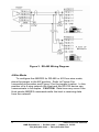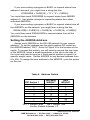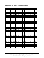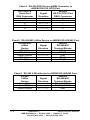
1
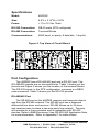
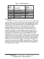
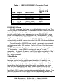
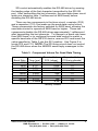
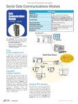
Distributed Smart Switch Model 485DSS Document No. 485DSS3298 This product Designed and Manufactured In Ottawa, Illinois USA of domestic and imported parts by B&B Electronics Mfg. Co. Inc. 707 Dayton Road -- P.O. Box 1040 -- Ottawa, IL 61350 PH (815) 433-5100 -- FAX (815) 434-7094 Internet: http://www.bb-elec.com [email protected] [email protected] 1998 B&B Electronics -- August 1998 TABLE OF CONTENTS CHAPTER 1: HARDWARE ...................................................................1 INTRODUCTION .........................................................................................1 Figure 1. Example of an RS-485/422 Multi-Node Network.......................1 CHECKLIST ...............................................................................................1 SPECIFICATIONS ........................................................................................2 Figure 2. Top View of Circuit Board...........................................................2 PORT CONFIGURATION..............................................................................2 RS-485/422 Port ..................................................................................2 Table 1. RS-422/485 Port ......................................................................3 RS-232 Port .........................................................................................3 Table 2. RS-232 DTE DB25P Connector Chart.....................................4 RS-422/485 Wiring ..............................................................................4 2-Wire Mode ........................................................................................4 Table 3. Component Values For Send Data Timing...............................5 Figure 3. RS-485 Wiring Diagram .............................................................6 4-Wire Mode ........................................................................................6 Figure 4. RS-422 Wiring Diagram .............................................................7 RS-485 AND RS-422 TERMINATION .........................................................7 POWER SUPPLY.........................................................................................7 OPERATION ...............................................................................................8 Figure 5. Simplified Functional Diagram ...................................................9 COMMUNICATION CONFIGURATION ..........................................................9 DISTRIBUTED SMART SWITCH COMMANDS...............................................9 The Command String .........................................................................10 ON Command ....................................................................................10 OFF Command ..................................................................................11 STATUS REQUEST Command ..........................................................11 SETTING THE 485DSS ADDRESS .............................................................14 Table 4. Address Switch.......................................................................14 BINARY FILE TRANSFER .........................................................................15 CHAPTER 2: SOFTWARE...................................................................16 DESCRIPTION .........................................................................................16 HARD DRIVE INSTALLATION...................................................................16 RUNNING DEMONSTRATION PROGRAM.................................................17 APPENDIX A: ASCII CHARACTER CODES .................................A-1 APPENDIX B: DECIMAL/HEXADECIMAL CONVERSIONS......B-1 Table 5. Hex/Dec Conversions ................................................................B-1 485DSS3298 Manual Table of Contents B&B Electronics -- PO Box 1040 -- Ottawa, IL 61350 PH (815) 433-5100 -- FAX (815) 434-7094 i APPENDIX C: CABLE CHARTS ......................................................C-1 CHART 1. IBM PC DB25 CONNECTOR TO ..........................................C-1 485DSS RS-232 (DTE) PORT ...........................................................C-1 CHART 3. RS-232 DCE DEVICE W/DB25 CONNECTOR TO ..................C-1 485DSS RS-232 (DTE) PORT ...........................................................C-1 CHART 2. IBM PC DB9 CONNECTOR TO ............................................C-1 485DSS RS-232 (DTE) PORT ...........................................................C-1 CHART 4. RS-232 DCE DEVICE W/DB9 CONNECTOR TO ....................C-2 485DSS RS-232 (DTE) PORT ...........................................................C-2 CHART 5. RS-422/485 4-WIRE DEVICE TO 485DSS RS-422/485PORT C-2 CHART 6. RS-485 2-WIRE DEVICE TO 485DSS RS-485/422 PORT. ....C-2 ii Table of Contents 485DSS3298 Manual B&B Electronics -- PO Box 1040 -- Ottawa, IL 61350 PH (815) 433-5100 -- FAX (815) 434-7094 Chapter 1: HARDWARE Introduction The RS-485 Distributed Smart Switch (485DSS) connects one RS-232 device to an RS-485 multi-node network as shown in Figure 1. To accomplish this, the 485DSS converts RS-232 to an addressable RS-485 node. A unique address, from 0 to 255, is user assigned by setting switches on the 485DSS. Figure 1. Example of an RS-485/422 Multi-Node Network Checklist The following items should be in the shipping carton: 1. RS-485 Distributed Smart Switch 2. Instruction Manual 3. (1) 3 1/2" floppy disk Contact the shippers immediately if any of the items above is missing or has damage. 485DSS3298 Manual B&B Electronics -- PO Box 1040 -- Ottawa, IL 61350 PH (815) 433-5100 -- FAX (815) 434-7094 1 Specifications Model: 485DSS Size: 4.8"L x 2.15"W x 0.9"H Power: +11 to 16 Vdc 75mA RS-232 Connection: DB-25 male (DTE configured) RS-485 Connection: Terminal Blocks Communications: 9600 baud, no parity, 8 data bits, 1 stop bit Figure 2. Top View of Circuit Board Port Configuration The 485DSS has a RS-485/422 port and a RS-232 port. The RS-485/422 signals are on terminal blocks. Table 1 shows you the pinouts and Figure 2 shows you the location of the terminal blocks. The RS-232 signal, in the DTE configuration, connects to a DB25 male connector. Table 2 shows you the RS-232 pinouts. RS-485/422 Port The RS-485 port on the 485DSS receives and transmits data to and from the RS-485 network. The RS-485 port has a balanced differential line driver and receiver. RS-485 allows up to 32 driver and receiver pairs to share a two-wire party line network. This port will operate on a 4-wire network and is compatible with RS-422 devices. Refer to B&B Electronics’ free RS-422/485 Application Note for more information. Refer to Appendix C for cable charts. 2 485DSS3298 Manual B&B Electronics -- PO Box 1040 -- Ottawa, IL 61350 PH (815) 433-5100 -- FAX (815) 434-7094 Table 1. RS-422/485 Port Terminal Block Signal FR GND TD(A)(-) TD(B)(+) RD(A)(-) RD(B)(+) GND +12VDC Description Frame Ground Transmit Data (A)(-) Transmit Data (B)(+) Receive Data (A)(-) Receive Data (B)(+) Signal Ground Power Supply RS-422/485 Signal Direction of Port <------> Output Output Input Input <------> Input RS-232 Port The RS-232 DTE port is an asynchronous port that supports TD and RD signals. In order to make the proper connections to the RS232 port. It is necessary to have a basic understanding of the terms DCE and DTE. The original design for connecting RS-232 devices together uses DB25 connectors, and connects a DTE (Data Terminal Equipment) device to a DCE (Data Communication Equipment) device. Each device will have inputs on pins that correspond to outputs on the same pins of the other device. For example, a DTE device transmits data out on pin 2 and a DCE device receives data in on pin 2. IBM PC's are DTE devices and modems are DCE devices. Only TD and RD of the RS-232 port pass through to the RS-485 port when the 485DSS is ON. The 485DSS raises and lowers the RTS output signal on the RS-232 port to reflect the connect state of the port. This signal can notify the RS232 device to start communicating to the Host or it can be an alarm output. The Host can monitor the CTS input line to determine if the RS-232 device is requesting access to the network. This input line could also be an alarm input. NOTE: If using RTS or CTS lines as alarms the user may have to design additional circuitry to properly interface to the alarm circuits. Refer to cable charts in Appendix C for making your own cables. 485DSS3298 Manual B&B Electronics -- PO Box 1040 -- Ottawa, IL 61350 PH (815) 433-5100 -- FAX (815) 434-7094 3 Table 2. RS-232 DTE DB25P Connector Chart Pin # 1 2 3 4 5 7 Signal FR GND TD RD RTS CTS SG Description Frame Ground Transmit Data Receive Data Request to Send Clear to Send Signal Ground Signal Direction of RS-232 DTE Port <------> Output Input Output Input <------> RS-422/485 Wiring RS-485 receivers also have an enable/disable control line. The 2W/4W jumper selects when to enable and disable RS-485 receiver. Setting the jumper to the 4W position constantly enables the receiver which is the same as operating in an RS-422/485 4-wire mode. In this position and connected to a 2-wire network, all data being transmitted by the RS-485 driver echos back through the RS485 receiver. Setting the jumper to 2W (RS-485, 2-wire mode) automatically enables the receiver when the RS-485 driver disables and visa versa. To configure the 485DSS for a typical 2-wire party line network, set the jumper in the 2W position. Refer to Figure 2 for the jumper location. The EIA RS-485 Specification labels data lines with an "A" and "B" designator. Some RS-485 equipment uses a "+" and "-" designator. In almost all cases, the "A" line is the equivalent of the "" line and the "B" line is the equivalent of the "+" line. See Figure 3 for a wiring example. 2-Wire Mode RS-485 allows half-duplex communications of multiple drivers having a control line for enabling and disabling (tri-stating) their outputs. When the 485DSS transmits a status reply message to the Host, the microcontroller will automatically enable the driver before transmitting the first character of the reply and disable the driver after the last character of the reply. When the 485DSS is ON (selected) and the RS-232 device is transmitting data to the Host the Send Data (SD) control circuit enables and disables the driver. The 485DSS disables the driver when it is not transmitting data to the Host and listens to (receives) all communications on the network. 4 485DSS3298 Manual B&B Electronics -- PO Box 1040 -- Ottawa, IL 61350 PH (815) 433-5100 -- FAX (815) 434-7094 SD control automatically enables the RS-485 driver by sensing the leading edge of the first character transmitted to the RS-232 port. After transmitting the last character, the send data timer circuit waits one character time (1 millisecond at 9600 baud) before disabling the RS-485 driver. There are two components in the timer circuit, a resistor (R15) and a capacitor (C10), that make up the send data control circuit. These components are factory selected for 9600 baud, allowing the send data control to operate at 9600 baud or higher. These two components disable the RS-485 driver approximately 1 millisecond after transmitting the last character. To change to a baud rate lower than 9600 baud, or to configure the send data control to match a specific baud rate of the RS-232 device, remove R15 and insert the value specified in Table 3 into the R21 position. Use Figure 2 to locate R15 and C10. NOTE: The SD timing circuit does not control the RS-485 driver when the 485DSS sends reply messages to the host. Table 3. Component Values For Send Data Timing Baud Rate 1200 2400 4800 9600* 19200 38400 56700 115200 Time (ms) 8.33 4.16 2.08 1.04* 0.520 0.260 0.176 0.0868 Resistor Value Capacitor Value R15 (ohms) C10(microfarads) 820K .01 430K .01 200K .01 100K* .01* 56K .01 27K .01 16K .01 8.2K .01 * Factory Default 485DSS3298 Manual B&B Electronics -- PO Box 1040 -- Ottawa, IL 61350 PH (815) 433-5100 -- FAX (815) 434-7094 5 Figure 3. RS-485 Wiring Diagram 4-Wire Mode To configure the 485DSS for RS-485 or 422 four-wire mode, place the jumper in the 4W position. Refer to Figure 4 for connecting information and Figure 2 for the jumper location. In this position on a 4-wire network the Host and the RS-232 device can communicate in full duplex. CAUTION: Data loss may occur if the Host sends 485DSS commands while the host is receiving data from the network! 6 485DSS3298 Manual B&B Electronics -- PO Box 1040 -- Ottawa, IL 61350 PH (815) 433-5100 -- FAX (815) 434-7094 Figure 4. RS-422 Wiring Diagram RS-485 and RS-422 Termination A jumper labeled “TERM” provides termination for the RS485/422 receiver. The termination resistor is a 120-ohm resistor placed between the RD (A) and RD (B) lines. To use this termination, place the jumper in the "IN" position. Refer to Figure 2 for the location of this jumper. If there is no need for termination, place the jumper in the "OUT" position. For more discussion of termination refer to B&B Electronics’ free RS-422/485 Application Note. Power Supply The 485DSS requires an unregulated DC power source that will supply +12 volts at 100 milliamps. Connect the positive side of the power source to the +12VDC terminal block and the common side of the power source to the GND terminal block. Refer to Figure 2 for the location of the terminal blocks and the polarity. B&B Electronics' power supply Model 485PS2 is available for the 485DSS. 485DSS3298 Manual B&B Electronics -- PO Box 1040 -- Ottawa, IL 61350 PH (815) 433-5100 -- FAX (815) 434-7094 7 Operation The host computer of the RS-485 network controls each 485DSS on the network by sending them command messages. These commands can turn a 485DSS on or off, and can also request status from an individual or from all of the 485DSS's on the network. The communication setup used to send and receive these commands are: 9600 baud, 8 data bits, no parity, and 1 stop bit. Each command consists of four characters: a start of message character, two address characters, and the command character. All 485DSS's on the network will receive the command message strings sent by the Host, but only the 485DSS with the matching address will execute the command. Execution of the ON command raises the Request To Send (RTS) output line on pin 4 of the DB25 connector and connects the RS-232 port to the RS-485 network. Once ON (selected), the RS-232 device can transmit and receive data to the HOST. Executing the OFF command lowers the RTS line, disconnecting the RS-232 port from the network. The RS-232 port of the 485DSS is OFF (not selected) at power up. The 485DSS does not buffer or delay any data passing through the unit. ALL data that is sent from the RS-485 device will be passed through to the RS-232 side while the unit is selected including the next set of command characters. The Host can poll any or all 485DSS's on the network using the request status command. This allows the Host to determine if any 485DSS is requesting access to the network by monitoring the handshake status character returned by the 485DSS. The status character reflects the state of the input handshake signal Clear To Send (CTS) on the RS-232 connector pin 5. With this feature the Host has the ability to prioritize each 485DSS on the network. Refer to Figure 2. 8 485DSS3298 Manual B&B Electronics -- PO Box 1040 -- Ottawa, IL 61350 PH (815) 433-5100 -- FAX (815) 434-7094 Figure 5. Simplified Functional Diagram Three red LED indicators are located on top of the 485DSS. The LED labeled TD flashes when the RS-232 device is transmitting data. The LED labeled RD flashes when data is being received by the 485DSS from the RS-485 network. The LED labeled SEL turns on indicating that the RS-232 device has access to the RS-485 network. Refer to Figure 2. Terminal blocks on the 485DSS connect the RS-485 signals, and input power to the unit. The RS232 DTE signals of the 485DSS connect to a DB25 male connector. An eight-position switch located in the top center of the 485DSS sets the 485DSS's unique address. Communication Configuration Before the HOST can communicate with a 485DSS, the HOST must set its communication format to: 9600 baud, 8 data bits, no parity, and 1 stop bit. After communicating with the 485DSS, the HOST can reset its communication format to match the format of the RS-232 device attached to the 485DSS. ALL data is passed through the unit after it has been selected. The 485DSS does not have any buffering. Distributed Smart Switch Commands The 485DSS constantly monitors the serial data received on the RS-485/422 port for a command string. There are only three commands required to control the 485DSS: the ON command, the OFF command, and the status request command. 485DSS3298 Manual B&B Electronics -- PO Box 1040 -- Ottawa, IL 61350 PH (815) 433-5100 -- FAX (815) 434-7094 9 The Command String All Command Strings consist of four ASCII characters. The first character is the start of message character, "X-off" (decimal 19). The second and third characters represent the hexadecimal address of an individual 485DSS. The address range is from 0 to 255 (HEX "00" to "FF"). Some commands require the use of the broadcast character "DC2" (decimal 18) as the second and third characters in the command. The fourth character is the command character. Command Syntax: X-off ____ ____ ____ | | | | | | | Command character. | | | Most signf. address character. Least signf. address character. Start of message character. ON Command This command turns on an individual 485DSS and asserts the RTS output handshake line on pin 4 of the DB25 connector. This command allows the RS-232 device connected to the 485DSS to access the RS-485 network. The address field in the command string specifies which 485DSS is to turn on. All other 485DSS's on the network will turn off if the address field does not match their address setting. Command character: SOH (decimal 1) Example 1: To turn on the 485DSS set to address 15 decimal (0F hex). HOST transmits: Xoff “0” “F” SOH ( 19 48 70 1 decimal) ( 13 30 46 1 hex) Example 2: To turn on the 485DSS set to address 33 decimal (21 hex). HOST transmits: 10 Xoff “2” “1” SOH ( 19 50 49 1 decimal) ( 13 32 31 1 hex) 485DSS3298 Manual B&B Electronics -- PO Box 1040 -- Ottawa, IL 61350 PH (815) 433-5100 -- FAX (815) 434-7094 If you were writing a program in BASIC to turn on address 10 decimal (0A hexadecimal) you might form a string like this: DSS0AON$ = CHR$(19) + "0" + "A" + CHR$(1) You could then send DSS0AON$ to select 485DSS address 10 (0A hex). Use similar strings for turning on the other 485DSS's. OFF Command This command turns off all 485DSS's on the network and lowers the RTS output handshake line on pin 4 of the DB25 connector. The command string consists of all non-printable ASCII characters. This command uses two broadcast characters "DC2" (decimal 18) in the address field. Sending this command before sending a command that has a specific address (address characters are printable) keeps the RS-232 device from outputting any printable characters. NOTE: This command permits only the use of the broadcast characters in the address field. Command character: EOT (decimal 4) Example 1: Turn off all the 485DSS's on the network. HOST transmits: Xoff DC2 DC2 EOT ( 19 18 18 4 decimal) ( 13 12 12 4 hex) The turn off string in BASIC might look like this: DSSOFF$ = CHR$(19) + CHR$(18) + CHR$(18) + CHR$(4) You could then send DSSOFF$ to turn off all 485DSS's. ALL data and control characters are passed through the 485DSS after it has been selected. STATUS REQUEST Command The Status Request command requests the status of an individual 485DSS or the status of all 485DSS's on the network. This command enables the Host computer to determine from each reply message received if the RS-232 device is requesting access to the network and if it has access to the network. By using this command the Host has the ability to prioritize all the 485DSS's on the network. A specific address in the address field specifies a response from an individual 485DSS. Placing broadcast characters 485DSS3298 Manual B&B Electronics -- PO Box 1040 -- Ottawa, IL 61350 PH (815) 433-5100 -- FAX (815) 434-7094 11 in the address field specifies all 485DSS's on the network. This command temporarily turns off (disconnect) the RS-232 port from the network while transmitting the reply message. The reply message transmitted by the 485DSS consists of six ASCII characters. The first character is the acknowledge character, an upper case "A" (decimal 65). The second and third characters represent the hexadecimal address of the 485DSS that sent the message. The address range is from 0 to 255 (HEX "00" to "FF"). The fourth character indicates the select state of 485DSS, a "0" (decimal 48) indicates the RS-232 port does not have a connection (not selected) to the network and a "1" (decimal 49) indicates the RS-232 port has a connection (selected) to the network. The fifth character indicates the state of the CTS handshake input line on pin 5 of the RS-232 port connector. A "0" (decimal 48) indicates a low state on the CTS input pin, and a "1" (decimal 49) indicates a high state on the CTS input pin. The sixth character is the end of message character, a carriage return (decimal 13). Reply Syntax: A ___ ___ ___ ___ cr | | | | | | | | | | | End of message char. | | | | Handshake input state. | | | | | | Most signf. address character. Select State. Least signf. address character. Start of message character. When this command contains a specific address, the 485DSS whose address matches the command address will wait for twenty milliseconds before transmitting the reply message. If the command uses the broadcast characters to receive status from all 485DSS's on the network each 485DSS will delay transmitting its reply based on its address. The amount of delay is equal to the unit's address in decimal multiplied by twenty milliseconds then add an additional 20 milliseconds. 12 485DSS3298 Manual B&B Electronics -- PO Box 1040 -- Ottawa, IL 61350 PH (815) 433-5100 -- FAX (815) 434-7094 Example: A unit with a decimal address of ten will have a delay of 220 milliseconds [(10 x 0.02) + 0.02 = 0.22 seconds]. Command character: ACK (decimal 6) Example 1: To request status from the 485DSS set to address 11 ( 0B hex) decimal. HOST transmits: Xoff “0” “B” ACK ( 19 48 66 6 decimal) ( 13 30 42 6 hex) Reply: “A” “0” “B” “0” “1” cr The reply indicates that the RS-232 port has no connection to the network on unit 11 and the CTS handshake line is in the high state. Example 2: Request status from all the 485DSS's on the network. HOST transmits: Xoff DC2 DC2 ACK ( 19 18 18 6 decimal) ( 13 12 12 6 hex) Reply: “A” “0” “1” “0” “0” cr Reply: “A” “0” “2” “1” “0” cr Reply: “A” “0” “3” “0” “0” cr Reply: “A” “1” “1” “0” “1” cr The reply indicates the following: Unit 1 waited 40 milliseconds and then sent a reply indicating no connection of the RS-232 port to the network and the CTS handshake line is in the low state. Unit 2 waited 60 milliseconds and then sent a reply indicating connection of the RS-232 port to the network and the CTS handshake line is in the low state. Unit 3 waited 80 milliseconds and then sent a reply indicating no connection of the RS-232 port to the network and the CTS handshake line is in the low state. Unit 17 decimal (11 hex) waited 360 milliseconds and then sent a reply indicating no connection of the RS-232 port to the network and the CTS handshake line is in the high state. 485DSS3298 Manual B&B Electronics -- PO Box 1040 -- Ottawa, IL 61350 PH (815) 433-5100 -- FAX (815) 434-7094 13 If you were writing a program in BASIC to request status from address 5 decimal, you might form a string like this: DSS05RS$ = CHR$(19) + "0" + "5" + CHR$(6) You could then send DSS05RS$ to request status from 485DSS address 5. Use similar strings for requesting status from other individual 485DSS's. If you were writing a program in BASIC to request status from all the 485DSS's on the network, you might form a string like this: DSSALLRS$ = CHR$(19) + CHR$(18) + CHR$(18) + CHR$(6) You could then send DSSALLRS$ to request status from all the 485DSS's on the network. Setting the 485DSS Address Assign each 485DSS on the RS-485 network its own unique address. To set the address use the eight position DIP switch on the 485DSS labeled “SW1”. Refer to Figure 2 for the location of the switch. To access this switch, you will need to remove the top cover of the 485DSS. Insert a small screwdriver in the slot in the side of the cover and twist to remove it. Each switch position is equal to a specific weight value. Set the 485DSS to any decimal address from 0 to 255. To assign the new address to the 485DSS, cycle the power on the unit. Table 4. Address Switch DECIMAL HEX DIP Switch 1 WEIGHT WEIGHT 1 1 1 2 2 2 3 4 4 4 8 8 5 16 10 6 32 20 7 64 40 8 128 80 OFF = Weight False ON = Weight True Factory Default Address = 0 14 485DSS3298 Manual B&B Electronics -- PO Box 1040 -- Ottawa, IL 61350 PH (815) 433-5100 -- FAX (815) 434-7094 Example 1: To set the address to decimal 21 (15 hex), you would turn on switches 1, 3, and 5 (1 + 4 + 16 = 21). Example 2: To set the address to 123 decimal (7B hex), turn on switches 1, 2, 4, 5, 6, and 7 (1 + 2 + 8 + 16 + 32 + 64 = 123). NOTE: It is important that the address you select is not already being used on the network! Binary File Transfer When transmitting binary files through the Distributed Smart Switch, it is possible that a string of characters could resemble a 485DSS command message. If this would happen, there could be a disruption in the transfer process and a loss of data. A simple solution to this problem is to change to a different baud rate before transferring binary files. 485DSS3298 Manual B&B Electronics -- PO Box 1040 -- Ottawa, IL 61350 PH (815) 433-5100 -- FAX (815) 434-7094 15 Chapter 2: SOFTWARE Description The Distributed Smart Switch Demonstration (DSS_DEMO) Program (IBM PC or Compatible) provides the user with examples of how to receive and transmit commands to the 485DSS. The DSS_DEMO.EXE is a DOS executable program written in QuickBasic that will send turn on, turn off, and status request commands to the 485DSS. The program also monitors reply messages from any or all 256 addresses. The source code is written in QuickBasic (DSS_DEMO.BAS), Borland Pascal (DSS_DEMO.PAS) and Borland and Microsoft C/C++ (DSS_DEMO.C). The source code provides an illustration of how to send and receive commands for the 485DSS. SimpCom Version 1.03+ is required to recompile DSS_DEMO.C and DSS_DEMO.PAS. This program is provided on one 3 1/2" 720K diskette. If a 5 1/4" diskette is required, please contact B&B Electronics. NOTE: This is a demonstration program only and not intended for system applications. Hard Drive Installation To install on your hard drive follow these steps: 1 Place the disk in drive A. 2 Go to a DOS prompt 3 Type A: and press the <ENTER> key. 4 Type INSTALL and press the <ENTER> key. A list of all files on the diskette is in the file "FILES.LST". 16 485DSS3298 Manual B&B Electronics -- PO Box 1040 -- Ottawa, IL 61350 PH (815) 433-5100 -- FAX (815) 434-7094 Running Demonstration Program Before you can run the demonstration program, you must run the install program described in the “Hard Drive Installation” section above. Make sure you have made the proper connections from the 485DSS to the RS-485 communication lines. If you are running Windows, exit Windows to DOS. To run the program follow these steps from the DOS prompt: QuickBasic Program 1. Type CD \485DSS and press the <Enter> key. 2. Type DSS_DEMO and press the <Enter> key. C Demo Program 1. Type CD\485DSS\C and press the <Enter> key. 2. Type DSS_DEMO and press the <Enter> key. Pascal Demo Program 1. Type CD\485DSS\PASCAL and press the <Enter> key. 2. Type DSS_DEMO and press the <Enter> key. 485DSS3298 Manual B&B Electronics -- PO Box 1040 -- Ottawa, IL 61350 PH (815) 433-5100 -- FAX (815) 434-7094 17 Appendix A: ASCII Character Codes DECIMAL to HEX to ASCII CONVERSION TABLE DEC HEX ASCII KEY DEC HEX ASCII DEC HEX ASCII DEC HEX ASCII 0 0 NUL ctrl @ 32 20 SP 64 40 @ 96 60 ` 1 1 SOH ctrl A 33 21 ! 65 41 A 97 61 a 2 2 STX ctrl B 34 22 “ 66 42 B 98 62 b 3 3 ETX ctrl C 35 23 # 67 43 C 99 63 c 4 4 EOT ctrl D 36 24 $ 68 44 D 100 64 d 5 5 ENQ ctrl E 37 25 % 69 45 E 101 65 e 6 6 ACK ctrl F 38 26 & 70 46 F 102 66 f 7 7 BEL ctrl G 39 27 ' 71 47 G 103 67 g 8 8 BS ctrl H 40 28 ( 72 48 H 104 68 h 9 9 HT ctrl I 41 29 ) 73 49 I 105 69 i 10 A LF ctrl J 42 2A * 74 4A J 106 6A j 11 B VT ctrl K 43 2B + 75 4B K 107 6B k 12 C FF ctrl L 44 2C , 76 4C L 108 6C l 13 D CR ctrl M 45 2D - 77 4D M 109 6D m 14 E SO ctrl N 46 2E . 78 4E N 110 6E n 15 F SI ctrl O 47 2F / 79 4F O 111 6F o 16 10 DLE ctrl P 48 30 0 80 50 P 112 70 p 17 11 DC1 ctrl Q 49 31 1 81 51 Q 113 71 q 18 12 DC2 ctrl R 50 32 2 82 52 R 114 72 r 19 13 DC3 ctrl S 51 33 3 83 53 S 115 73 s 20 14 DC4 ctrl T 52 34 4 84 54 T 116 74 t 21 15 NAK ctrl U 53 35 5 85 55 U 117 75 u 22 16 SYN ctrl V 54 36 6 86 56 V 118 76 v 23 17 ETB ctrl W 55 37 7 87 57 W 119 77 w 24 18 CAN ctrl X 56 38 8 88 58 X 120 78 x 25 19 EM ctrl Y 57 39 9 89 59 Y 121 79 y 26 1A SUB ctrl Z 58 3A : 90 5A Z 122 7A z 27 1B ESC ctrl [ 59 3B ; 91 5B [ 123 7B { 28 1C FS ctrl \ 60 3C < 92 5C \ 124 7C | 29 1D GS ctrl ] 61 3D = 93 5D ] 125 7D } 30 1E RS ctrl ^ 62 3E > 94 5E ^ 126 7E ~ 31 1F US ctrl _ 63 3F ? 95 5F _ 127 7F DEL 485DSS3298 Manual Appendix A B&B Electronics -- PO Box 1040 -- Ottawa, IL 61350 PH (815) 433-5100 -- FAX (815) 434-7094 A-1 Appendix B: Decimal/Hexadecimal/Conversions The decimal (base 10) numbering system represents each position in successive powers of 10, with each decimal symbol having a value from 0 to 9. The hexadecimal (base 16) numbering system represents each position in successive powers of 16 with each hex symbol having a value of 0 to 15. Since each hex position must have a single symbol, the symbols "A" through "F" are assigned to values 10 through 15 respectively. Refer to Table 1. The information and examples to follow will explain how to convert from a decimal number to a hexadecimal number and vice versa. Table 5. Dec/Hex Conversions Decimal Value 0 1 2 3 4 5 6 7 8 9 10 11 12 13 14 15 485DSS3298 Manual Hexadecimal Symbol 0 1 2 3 4 5 6 7 8 9 A B C D E F Appendix B B&B Electronics -- PO Box 1040 -- Ottawa, IL 61350 PH (815) 433-5100 -- FAX (815) 434-7094 B-1 Hexadecimal to Decimal Conversion: Each “Hex digit” is the decimal equivalent value of the hexadecimal symbol. Example: Convert 10FC hexadecimal to decimal. Decimal = (1st Hex digit x 4096) + (2nd Hex digit x 256) + (3rd Hex digit x 16) + (4th Hex digit) 1 0 15 12 x x x x 4096 256 16 1 = = = = 4096 0 240 12 4348 10FC hex equals 4348 decimal. 4348 decimal equals 10FC hexadecimal. Decimal to Hexadecimal Conversion: Example: Convert 4348 decimal to hexadecimal. 4348 decimal equals 10FC hexadecimal. 4096 256 16 1 B-2 4348 4096 252 0 252 240 12 12 0 = 1 = 1 (1st Hex digit) = 0 = 0 (2nd Hex digit) = 15 = F (3rd Hex digit) = 12 = C (4th Hex digit) Appendix B 485DS32985 Manual B&B Electronics -- PO Box 1040 -- Ottawa, IL 61350 PH (815) 433-5100 -- FAX (815) 434-7094 Appendix C: Cable Charts These charts indicate some common cable wiring based on the 485DSS RS-232 and RS-485/422 ports. Refer to the Port Configuration section of this manual for more information. Chart 1. IBM PC DB25 Connector to 485DSS RS-232 (DTE) Port IBM PC 485DSS Serial Port Signal RS-232 (DTE) Port DB25 Connector Direction DB25 Connector 2 -----------> 3 3 <----------2 4 -----------> 5 5 <----------4 7 <---------> 7 Chart 2. IBM PC DB9 Connector to 485DSS RS-232 (DTE) Port IBM PC 485DSS Serial Port Signal RS-232 (DTE) Port DB9 Connector Direction DB25 Connector 3 -----------> 3 2 <----------2 7 -----------> 5 8 <----------4 5 <---------> 7 Chart 3. RS-232 DCE Device w/DB25 Connector to 485DSS RS-232 (DTE) Port RS-232 DCE 485DSS Serial Port Signal RS-232 (DTE) Port DB25 Connector Direction DB25 Connector 2 <----------2 3 -----------> 3 4 <---------4 5 -----------> 5 7 <----------> 7 485DSS3298 Manual Appendix C B&B Electronics -- PO Box 1040 -- Ottawa, IL 61350 PH (815) 433-5100 -- FAX (815) 434-7094 C-1 Chart 4. RS-232 DCE Device w/DB9 Connector to 485DSS RS-232 (DTE) Port RS-232 DCE 485DSS Serial Port Signal RS-232 (DTE) Port DB9 Connector Direction DB25 Connector 2 -----------> 3 3 <----------2 5 <---------> 7 7 <----------4 8 -----------> 5 Chart 5. RS-422/485 4-Wire Device to 485DSS RS-422/485 Port. RS-422/485 485DSS 4-Wire Signal RS-485/422 Device Direction Terminal Blocks TD (A)(-) -----------> RD (A) TD (B)(+) -----------> RD (B) Signal Ground <----------> GND RD (A)(-) <----------TD (A) RD (B)(+) <----------TD (B) Chart 6. RS-485 2-Wire Device to 485DSS RS-485/422 Port. RS-485 485DSS 2-Wire Signal RS-485/422 Device Direction Terminal Blocks Data (A)(-) <----------> TD (A) & RD(A) Data (B)(+) <----------> TD (B) & RD(B) Signal Ground <----------> GND C-2 Appendix C 485DS32985 Manual B&B Electronics -- PO Box 1040 -- Ottawa, IL 61350 PH (815) 433-5100 -- FAX (815) 434-7094 FEDERAL COMMUNICATIONS COMMISSION RADIO FREQUENCY INTERFACE STATEMENT Class A Equipment This equipment has been tested and found to comply with the limits for Class A digital device, pursuant to Part 15 of the FCC Rules. These limits are designed to provide reasonable protection against harmful interference when the equipment is operated in a commercial environment. This equipment generates, uses, and can radiate radio frequency energy and, if not installed and used in accordance with the instructions, may cause harmful interference to radio communications. Operation of this equipment in a residential area is likely to cause harmful interference, in which case the user will be required to correct the interference at personal expense. FCC Class A Equipment Statement