1
Using the
Bay Command Console
Router Software Version 11.01
Site Manager Software Version 5.01
Part No. 115976-A Rev. A
February 1997
4401 Great America Parkway
Santa Clara, CA 95054
8 Federal Street
Billerica, MA 01821
Copyright © 1988–1997 Bay Networks, Inc.
All rights reserved. Printed in the USA. February 1997.
The information in this document is subject to change without notice. The statements, configurations, technical data,
and recommendations in this document are believed to be accurate and reliable, but are presented without express or
implied warranty. Users must take full responsibility for their applications of any products specified in this document.
The information in this document is proprietary to Bay Networks, Inc.
The software described in this document is furnished under a license agreement and may only be used in accordance
with the terms of that license. A summary of the Software License is included in this document.
Restricted Rights Legend
Use, duplication, or disclosure by the United States Government is subject to restrictions as set forth in subparagraph
(c)(1)(ii) of the Rights in Technical Data and Computer Software clause at DFARS 252.227-7013.
Notice for All Other Executive Agencies
Notwithstanding any other license agreement that may pertain to, or accompany the delivery of, this computer
software, the rights of the United States Government regarding its use, reproduction, and disclosure are as set forth in
the Commercial Computer Software-Restricted Rights clause at FAR 52.227-19.
Trademarks of Bay Networks, Inc.
ACE, AFN, AN, BCN, BLN, BN, BNX, CN, FN, FRE, GAME, LN, Optivity, PPX, Bay Networks, SynOptics,
SynOptics Communications, Wellfleet and the Wellfleet logo are registered trademarks and ANH, ASN, Bay•SIS,
BCNX, BLNX, EZ Install, EZ Internetwork, EZ LAN, PathMan, PhonePlus, Quick2Config, RouterMan, SPEX,
Bay Networks Press, the Bay Networks logo and the SynOptics logo are trademarks of
Bay Networks, Inc.
Third-Party Trademarks
All other trademarks and registered trademarks are the property of their respective owners.
Statement of Conditions
In the interest of improving internal design, operational function, and/or reliability, Bay Networks, Inc. reserves the
right to make changes to the products described in this document without notice.
Bay Networks, Inc. does not assume any liability that may occur due to the use or application of the product(s) or
circuit layout(s) described herein.
Portions of the code in this software product are Copyright © 1988, Regents of the University of California. All rights
reserved. Redistribution and use in source and binary forms of such portions are permitted, provided that the above
copyright notice and this paragraph are duplicated in all such forms and that any documentation, advertising materials,
and other materials related to such distribution and use acknowledge that such portions of the software were
developed by the University of California, Berkeley. The name of the University may not be used to endorse or
promote products derived from such portions of the software without specific prior written permission.
SUCH PORTIONS OF THE SOFTWARE ARE PROVIDED “AS IS” AND WITHOUT ANY EXPRESS OR
IMPLIED WARRANTIES, INCLUDING, WITHOUT LIMITATION, THE IMPLIED WARRANTIES OF
MERCHANTABILITY AND FITNESS FOR A PARTICULAR PURPOSE.
In addition, the program and information contained herein are licensed only pursuant to a license agreement that
contains restrictions on use and disclosure (that may incorporate by reference certain limitations and notices imposed
by third parties).
ii
115976-A Rev. A
Bay Networks Software License
Note: This is Bay Networks basic license document. In the absence of a
software license agreement specifying varying terms, this license -- or the
license included with the particular product -- shall govern licensee’s use of
Bay Networks software.
This Software License shall govern the licensing of all software provided to licensee by Bay Networks (“Software”).
Bay Networks will provide licensee with Software in machine-readable form and related documentation
(“Documentation”). The Software provided under this license is proprietary to Bay Networks and to third parties from
whom Bay Networks has acquired license rights. Bay Networks will not grant any Software license whatsoever, either
explicitly or implicitly, except by acceptance of an order for either Software or for a Bay Networks product
(“Equipment”) that is packaged with Software. Each such license is subject to the following restrictions:
1.
Upon delivery of the Software, Bay Networks grants to licensee a personal, nontransferable, nonexclusive license
to use the Software with the Equipment with which or for which it was originally acquired, including use at any
of licensee’s facilities to which the Equipment may be transferred, for the useful life of the Equipment unless
earlier terminated by default or cancellation. Use of the Software shall be limited to such Equipment and to such
facility. Software which is licensed for use on hardware not offered by Bay Networks is not subject to restricted
use on any Equipment, however, unless otherwise specified on the Documentation, each licensed copy of such
Software may only be installed on one hardware item at any time.
2.
Licensee may use the Software with backup Equipment only if the Equipment with which or for which it was
acquired is inoperative.
3.
Licensee may make a single copy of the Software (but not firmware) for safekeeping (archives) or backup
purposes.
4.
Licensee may modify Software (but not firmware), or combine it with other software, subject to the provision
that those portions of the resulting software which incorporate Software are subject to the restrictions of this
license. Licensee shall not make the resulting software available for use by any third party.
5.
Neither title nor ownership to Software passes to licensee.
6.
Licensee shall not provide, or otherwise make available, any Software, in whole or in part, in any form, to any
third party. Third parties do not include consultants, subcontractors, or agents of licensee who have licensee’s
permission to use the Software at licensee’s facility, and who have agreed in writing to use the Software only in
accordance with the restrictions of this license.
7.
Third-party owners from whom Bay Networks has acquired license rights to software that is incorporated into
Bay Networks products shall have the right to enforce the provisions of this license against licensee.
8.
Licensee shall not remove or obscure any copyright, patent, trademark, trade secret, or similar intellectual
property or restricted rights notice within or affixed to any Software and shall reproduce and affix such notice on
any backup copy of Software or copies of software resulting from modification or combination performed by
licensee as permitted by this license.
115976-A Rev. A
iii
Bay Networks Software License (continued)
9.
Licensee shall not reverse assemble, reverse compile, or in any way reverse engineer the Software. [Note: For
licensees in the European Community, the Software Directive dated 14 May 1991 (as may be amended from time
to time) shall apply for interoperability purposes. Licensee must notify Bay Networks in writing of any such
intended examination of the Software and Bay Networks may provide review and assistance.]
10. Notwithstanding any foregoing terms to the contrary, if licensee licenses the Bay Networks product “Site
Manager,” licensee may duplicate and install the Site Manager product as specified in the Documentation. This
right is granted solely as necessary for use of Site Manager on hardware installed with licensee’s network.
11. This license will automatically terminate upon improper handling of Software, such as by disclosure, or Bay
Networks may terminate this license by written notice to licensee if licensee fails to comply with any of the
material provisions of this license and fails to cure such failure within thirty (30) days after the receipt of written
notice from Bay Networks. Upon termination of this license, licensee shall discontinue all use of the Software
and return the Software and Documentation, including all copies, to Bay Networks.
12. Licensee’s obligations under this license shall survive expiration or termination of this license.
iv
115976-A Rev. A
Contents
About This Guide
Audience ........................................................................................................................... xi
Before You Begin ..............................................................................................................xii
Conventions ......................................................................................................................xii
Acronyms .........................................................................................................................xiv
Ordering Bay Networks Publications ...............................................................................xiv
Technical Support and Online Services
Bay Networks Customer Service .....................................................................................xvi
Bay Networks Information Services ................................................................................xvii
World Wide Web .......................................................................................................xvii
Customer Service FTP .............................................................................................xvii
Support Source CD ................................................................................................. xviii
CompuServe ........................................................................................................... xviii
InfoFACTS .................................................................................................................xix
How to Get Help ..............................................................................................................xix
Chapter 1
Overview
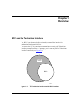
BCC and the Technician Interface ..................................................................................1-1
Platform Requirements ...................................................................................................1-2
Configurable Objects ......................................................................................................1-2
Terminology and Concepts .............................................................................................1-3
Naming and Numbering Conventions .............................................................................1-9
Using Abbreviations and Acronyms ..............................................................................1-10
Command Groups ........................................................................................................1-11
115976-A Rev. A
v
Chapter 2
Learning to Use the BCC Interface
Entering and Exiting the BCC Interface ..........................................................................2-1
About the BCC Configuration Hierarchy .........................................................................2-2
Configuration Context ..............................................................................................2-5
Displaying Context ...................................................................................................2-5
Context-Sensitive Prompts .......................................................................................2-6
Navigating the Configuration Hierarchy ..........................................................................2-6
Changing Context Levels .........................................................................................2-7
Moving Back One Level .....................................................................................2-7
Moving Back to Root Context ............................................................................2-8
Specifying Context ...................................................................................................2-8
Moving Back One or More Levels ......................................................................2-9
Moving Forward One Level ................................................................................2-9
Specifying an Absolute Path Description .........................................................2-10
Specifying a Shortened Path Description ........................................................2-11
Displaying Online Help .................................................................................................2-12
Getting Root-Level (System) Help ..........................................................................2-13
Getting Help for Configurable Objects and Attributes ............................................2-15
Getting Help for Configurable Attribute Values .......................................................2-16
Displaying Assigned Attribute Values .....................................................................2-17
Displaying Configuration Data ......................................................................................2-18
Displaying the Total Device Configuration ..............................................................2-18
Displaying Objects within a Specific Context .........................................................2-20
Displaying Binary Configuration Files as BCC Syntax ...........................................2-22
Entering Commands .....................................................................................................2-24
Command Input Features ......................................................................................2-24
Using Command Recognition ..........................................................................2-24
Recalling Commands ......................................................................................2-25
Reading (Sourcing) Commands from a File ....................................................2-25
Entering Multiple Commands per Line ............................................................2-26
Continuing a Command Line ...........................................................................2-26
Entering Comments .........................................................................................2-26
Using Lists .......................................................................................................2-27
System Commands ................................................................................................2-27
vi
115976-A Rev. A
Configuration Commands ......................................................................................2-29
Using Basic (Full) Syntax ................................................................................2-29
Using Default Syntax .......................................................................................2-30
Discovering the Sequence of Required Attributes for an Object .....................2-31
Using Abbreviated Syntax ...............................................................................2-32
Specifying Attribute Values ..............................................................................2-32
Command Operators ..............................................................................................2-34
Editing Commands .......................................................................................................2-37
Chapter 3
Configuring a Network Device
Configured Objects .........................................................................................................3-1
Creating a New Configuration ........................................................................................3-3
Modifying an Existing Configuration .............................................................................3-13
Sourcing Configuration Commands from a File ............................................................3-14
Disabling a Configured Object ......................................................................................3-15
Enabling a Configured Object .......................................................................................3-15
Deleting a Configured Object .......................................................................................3-16
Configuration Command Responses ............................................................................3-17
Chapter 4
Examples
Identifying Link Modules Residing in a Device ...............................................................4-2
Configuring an Ethernet Interface with IP, ARP, and RIP ................................................4-3
Configuring a HSSI Port with IP .....................................................................................4-4
Configuring a Token Ring Interface with IP and RIP .......................................................4-6
Configuring PPP, IP, and an Adjacent Host (Sync Interface) ..........................................4-7
Configuring a FDDI Interface with IP and RIP ................................................................4-8
Configuring OSPF and BGP .........................................................................................4-10
Configuring TELNET, FTP, SNMP, and NTP .................................................................4-17
Index
115976-A Rev. A
vii
Figures
Figure 1-1.
Figure 2-1.
Figure 2-2.
Figure 2-3.
Figure 2-5.
Figure 2-6.
Figure 3-1.
The Technician Interface and the BCC Interface ......................................1-1
Example BCC Configuration (BN Router) ................................................2-3
Moving Back (Toward Root) One Context Level at a Time .......................2-7
Moving Immediately Back to the Root Context Level ...............................2-8
Specifying an Absolute Path ..................................................................2-11
Allowing the BCC to Search for a Context You Specify ..........................2-12
Comparing BCC Configuration to OSI Protocol Layering ........................3-4
Figure 3-2.
Figure 3-3.
Example BCC Configuration ....................................................................3-5
Typical BCC Configuration Cycle ...........................................................3-12
115976-A Rev. A
ix
About This Guide
If you are responsible for configuring and managing Bay Networks® routers, you
need to read this guide. This guide provides an overview of the Bay Command
Console (BCC™), an object-oriented command line interface supporting
simplified device configuration.
This guide provides
•
An overview of the BCC user interface environment
•
A detailed description of how to perform basic BCC operations
•
Information about how to configure the router using BCC commands
•
Examples that illustrate how to configure, navigate, get help, and perform
other system tasks
Audience
A typical user of the BCC should have moderate to significant experience
supporting a multivendor internetworking system. This user commonly performs
network device configuration, maintenance, and troublehooting tasks, and has
experience using command line interfaces on other networking products.
115976-A Rev. A
xi
Using the Bay Command Console
Before You Begin
Caution: Because the BCC performs realtime changes to a device
configuration, we recommend that you first learn BCC behavior on a device
not connected to your production network. Once you become comfortable
with using the BCC, you can run it on a device in your production network.
If you are installing the 11.01 software on a new router, you should first
•
Install the router (refer to the installation manual that came with your router).
•
Connect the router to the network and create a pilot configuration file (refer to
Quick-Starting Routers).
Make sure that you are running the latest version of Bay Networks Site Manager
and router software. For instructions, refer to Upgrading Routers from Version
7–8.00 to Version 11.01.
If you are upgrading an existing router to run the 11.01 software , follow the
instructions in Upgrading Routers from Version 7–8.00 to Version 11.01.
Conventions
This guide uses the following conventions:
angle brackets (<xyz>)
Indicates a variable in a command line. The name
between the angle brackets generically describes the
type of variable (e.g., <host-address>, <encaps>,
<max-interval>). Do not type the angle brackets when
entering an actual value for a variable.
Example: if command syntax is ping <ip-address>,
enter ping 192.32.10.12
bold text
Indicates text (usually commands) that you enter at the
BCC command line prompt.
braces ({ })
Indicate BCC keywords or attribute-value pairs
required by the BCC as command input.
Also indicates a list of elements (for example, a list of
circuit names or IP addresses):
xii
115976-A Rev. A
About This Guide
Example:
ip/1.2.3.4> info
group {ethernet/2/1}
state enabled
sub-protocols {arp/1.2.3.4/1 rip/1.2.3.4}
address 1.2.3.4
mask 255.0.0.0
.
.
.
.
brackets ([ ])
Indicate command keywords, arguments, or filters not
required (taken as optional command input) by the
BCC.
vertical line (|)
Separates choices for required or optional command
keywords and arguments. You must enter only one of
the choices available for a command keyword or
argument. Do not type the vertical line when entering a
command.
Example: If the command syntax is
show at {routes | nets}, enter
show at routes
italic text
Indicates variable values in command syntax
descriptions, new terms, file and directory names, and
book titles.
quotation marks (“ ”)
Indicates a literal string in a command line. Also
indicates the title of a chapter or section within a book.
screen text
Indicates BCC or Technician Interface outputs to a
console or TELNET screen, such as prompts, system
messages, statistical data, and configuration data.
.
Horizontal (. . .) and vertical ( .. ) ellipsis points indicate
omitted information.
ellipsis points
115976-A Rev. A
or show at nets
xiii
Using the Bay Command Console
Acronyms
AS
Autonomous System
BGP
Border Gateway Protocol
BofL
Breath of Life
IP
Internet Protocol
LAN
local area network
MAC
media access control
NTP
Network Time Protocol
OSI
Open Systems Interconnection
OSPF
Open Shortest Path First (Protocol)
PPP
Point-to-Point Protocol
PVC
Permanent Virtual Circuit
RIP
Routing Information Protocol
SNMP
Simple Network Management Protocol
SVC
Switched Virtual Circuit
TCP/IP
Transmission Control Protocol/Internet Protocol
TELNET
Telecommunication Network
TFTP
Trivial File Transfer Protocol
WAN
wide area network
Ordering Bay Networks Publications
To purchase additional copies of this document or other Bay Networks
publications, order by part number from the Bay Networks Press™ at the following
telephone or fax numbers:
• Telephone - U.S./Canada
• Telephone - International
• Fax
1-888-4BAYPRESS
1-510-490-4752
1-510-498-2609
You can also use these numbers to request a free catalog of Bay Networks Press
product publications.
xiv
115976-A Rev. A
Technical Support and Online Services
To ensure comprehensive network support to our customers and partners
worldwide, Bay Networks Customer Service has Technical Response Centers
in key locations around the globe:
•
•
•
•
•
Billerica, Massachusetts
Santa Clara, California
Sydney, Australia
Tokyo, Japan
Valbonne, France
The Technical Response Centers are connected via a redundant Frame Relay
Network to a Common Problem Resolution system, enabling them to transmit and
share information, and to provide live, around-the-clock support 365 days a year.
Bay Networks Information Services complement the Bay Networks Service
program portfolio by giving customers and partners access to the most current
technical and support information through a choice of access/retrieval means.
These include the World Wide Web, CompuServe, Support Source CD, Customer
Service FTP, and InfoFACTS document fax service.
115976-A Rev. A
xv
Using the Bay Command Console
Bay Networks Customer Service
If you purchased your Bay Networks product from a distributor or authorized
reseller, contact that distributor’s or reseller’s technical support staff for assistance
with installation, configuration, troubleshooting, or integration issues.
Customers can also purchase direct support from Bay Networks through a variety
of service programs. As part of our PhonePlus™ program, Bay Networks Service
sets the industry standard, with 24-hour, 7-days-a-week telephone support
available worldwide at no extra cost. Our complete range of contract and
noncontract services also includes equipment staging and integration, installation
support, on-site services, and replacement parts delivery -- with response times
ranging to 4 hours, depending on local country conditions.
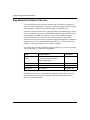
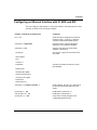
To purchase any of the Bay Networks support programs, or if you have questions
on program features, use the following numbers:
Region
Telephone Number
Fax Number
United States and
Canada
1-800-2LANWAN; enter Express Routing
Code (ERC) 290 when prompted
(508) 670-8766
(508) 916-8880 (direct)
Europe
(33) 92-4-968-300
(33) 92-4-968-301
Asia/Pacific
(612) 9927-8800
(612) 9927-8811
Latin America
(561) 988-7661
(561) 988-7750
In addition, you can receive information on support programs from your local
Bay Networks field sales office, or purchase Bay Networks support directly
from your authorized partner.
xvi
115976-A Rev. A
Technical Support and Online Services
Bay Networks Information Services
Bay Networks Information Services provide up-to-date support information as a
first-line resource for network administration, expansion, and maintenance. This
information is available from a variety of sources.
World Wide Web
The Bay Networks Customer Support Web Server offers a diverse library of
technical documents, software agents, and other important technical information
to Bay Networks customers and partners.
A special benefit for contracted customers and resellers is the ability to access the
Web Server to perform Case Management. This feature enables your support staff
to interact directly with the network experts in our worldwide Technical Response
Centers. A registered contact with a valid Site ID can
•
View a listing of support cases and determine the current status of any open
case. Case history data includes severity designation, and telephone, e-mail,
or other logs associated with the case.
•
Customize the listing of cases according to a variety of criteria, including
date, severity, status, and case ID.
•
Log notes to existing open cases.
•
Create new cases for rapid, efficient handling of noncritical network
situations.
•
Communicate directly via e-mail with the specific technical resources
assigned to your case.
The Bay Networks URL is http://www.baynetworks.com. Customer Service is a
menu item on that home page.
Customer Service FTP
Accessible via URL ftp://support.baynetworks.com (134.177.3.26), this site
combines and organizes support files and documentation for the entire Bay
Networks product suite. Central management and sponsorship of this FTP site lets
you quickly locate information on any of your Bay Networks products.
115976-A Rev. A
xvii
Using the Bay Command Console
Support Source CD
This CD-ROM -- sent quarterly to all contracted customers -- is a complete Bay
Networks Service troubleshooting knowledge database with an intelligent text
search engine.
The Support Source CD contains extracts from our problem-tracking database;
information from the Bay Networks Forum on CompuServe; comprehensive
technical documentation, such as Customer Support Bulletins, Release Notes,
software patches and fixes; and complete information on all Bay Networks
Service programs.
You can run a single version on Macintosh, Windows 3.1, Windows 95,
Windows NT, DOS, or UNIX computing platforms. A Web links feature enables
you to go directly from the CD to various Bay Networks Web pages.
CompuServe
For assistance with noncritical network support issues, Bay Networks Information
Services maintain an active forum on CompuServe, a global bulletin-board
system. This forum provides file services, technology conferences, and a message
section to get assistance from other users.
The message section is monitored by Bay Networks engineers, who provide
assistance wherever possible. Customers and resellers holding Bay Networks
service contracts also have access to special libraries for advanced levels of
support documentation and software. To take advantage of CompuServe’s recently
enhanced menu options, the Bay Networks Forum has been redesigned to allow
links to our Web sites and FTP sites.
We recommend the use of CompuServe Information Manager software to access
these Bay Networks Information Services resources. To open an account and
receive a local dial-up number in the United States, call CompuServe at
1-800-524-3388. Outside the United States, call 1-614-529-1349, or your nearest
CompuServe office. Ask for Representative No. 591. When you are online with
your CompuServe account, you can reach us with the command GO BAYNET.
xviii
115976-A Rev. A
Technical Support and Online Services
InfoFACTS
InfoFACTS is the Bay Networks free 24-hour fax-on-demand service. This
automated system has libraries of technical and product documents designed to
help you manage and troubleshoot your Bay Networks products. The system
responds to a fax from the caller or to a third party within minutes of being
accessed.
To use InfoFACTS in the United States or Canada, call toll-free 1-800-786-3228.
Outside North America, toll calls can be made to 1-408-495-1002. In Europe,
toll-free numbers are also available for contacting both InfoFACTS and
CompuServe. Please check our Web page for the listing in your country.
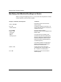
How to Get Help
Use the following numbers to reach your Bay Networks Technical Response
Center:
115976-A Rev. A
Technical Response Center Telephone Number
Fax Number
Billerica, MA
1-800-2LANWAN
(508) 670-8765
Santa Clara, CA
1-800-2LANWAN
(408) 764-1188
Valbonne, France
(33) 92-4-968-968
(33) 92-4-966-998
Sydney, Australia
(612) 9927-8800
(612) 9927-8811
Tokyo, Japan
(81) 3-5402-0180
(81) 3-5402-0173
xix
Chapter 1
Overview
BCC and the Technician Interface
The BCC is an enhanced (object-oriented) command line interface for
configuring Bay Networks devices.
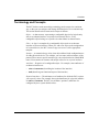
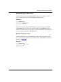
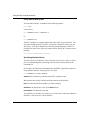
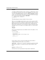
You access the BCC by entering a command (bcc-trial) at the Technician
Interface prompt. From the bcc> prompt, you can run any BCC or Technician
Interface commands (see Figure 1-1).
Technician
Interface
BCC
BCC0001A
Figure 1-1.
115976-A Rev. A
The Technician Interface and the BCC Interface
1-1
Using the Bay Command Console
With the BCC interface, you use commands primarily to perform tasks related to
device configuration, such as defining network interfaces and examining
configuration data. For tasks related to device management (managing files on the
router, viewing router statistics or the router events log, and so on), you enter
Technician Interface commands at the BCC command line prompt. (More
information on this follows in the section “System Commands” in Chapter 2.
Note: For more information on Technician Interface commands and scripts,
refer to
• Using Technician Interface Software
• Using Technician Interface Scripts
• Writing Technician Interface Scripts
In future releases of the router software, Technician Interface functionality will
decrease and BCC functionality will evolve and expand.
Platform Requirements
The BCC software runs on BN® platforms (BLN and BCN routers) with FRE®-2
processor modules that each have 16 MB DRAM installed.
Configurable Objects
Refer to the latest Release Notes and Read Me First publications for the most
accurate information on what you can configure using the BCC on a specific
platform.
1-2
115976-A Rev. A
Overview
Terminology and Concepts
The BCC defines certain networking terminology and concepts in a consistent
way, so that you can configure and manage different devices in a consistent way.
This section describes these terms and concepts as follows:
Object -- A data structure representing a configurable physical or logical entity
such as an ethernet interface or a protocol on a network device. Every
configurable object belongs to a specific class that defines its characteristics.
Class -- A class is a template for a configurable object (such as an ethernet
interface or IP on an interface). When you add a new object to the configuration
of a network device, the BCC creates a copy (an instance) of the appropriate
template.
Instance -- A customized copy of any class object defined in the configuration tree
for a Bay Networks device. For example, you can create (add) an instance of the
protocol IP to run on a specific interface type, slot, and connector in a Model BLN
router. You customize an instance with unique values for its required attributes.
Attributes -- Properties of a configurable object. For example, some attributes of
an ethernet interface are
•
slot and connector (describing the location of the interface)
•
bofl (describing one functional aspect of the interface)
Required Attributes -- The minimum set of attributes for which the BCC requires
you to specify values. For example, the required attributes for a physical interface
are slot and connector. The BCC sets all other (“optional”) attributes of a
configured object to system default values.
115976-A Rev. A
1-3
Using the Bay Command Console
Optional Attributes -- The set of attributes for which you can optionally specify
customized values, replacing any default values set by the system. For example,
an optional attribute of an ethernet interface is bofl (Breath Of Life). The default
value or setting for bofl is enabled; you can optionally change this to disabled.
Instance Identifier -- Uniquely identifies a single instance of an object configured
on a Bay Networks device. The instance ID consists typically of the name of an
object, combined with the values you specify for its required attributes. For
example, the instance ID for an ethernet interface consists of
ethernet/<slot>/<connector>. For some objects, the BCC automatically appends
other (internal) data to make each instance ID unique across the entire device
configuration.
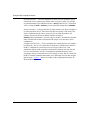
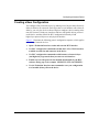
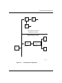
Configuration Hierarchy -- Classes (templates for creating objects) exist within a
tree hierarchy. Just as a file system has a root directory, subdirectores, and files,
the BCC configuration system has a root level object (called “box”) and
subordinate objects (such as interfaces and protocols) that fan out from the root
level in a tree hierarchy. The BCC configuration command hierarchy varies
according to the type of network device (for example, a router, hub, or switch), but
the BCC includes commands that enable you to efficiently discover and navigate
that hierarchy. Figure 1-2 shows an example of the configuration hierarchy for
BLN and BCN routers.
1-4
115976-A Rev. A
Overview
ntp
peer
area
tftp
ospf
accept
arp
announce
network
network
networks
from-as
to-peer
networks
aggr-as
rip-gateway
from-peer
rip-interface
ip
tcp
console
igmp
peer
aggr-router
from-as
ftp
bgp
accept
orig-as
from-next-hop
inject
egp-peer
static-route
announce
egp-peer-as
network
access-policy
to-as
trusted-host
snmp
community
from-peer
manager
advertise
trap-entity
trap-event
telnet
client
Global Services
Logical interface services
ethernet
fddi
tokenring
rip
ospf
ip
rdisc
ospf
virtual
arp
ip
arp
igmp
rip
Line
interface
services
ppp
ip
ospf
line
arp
rip
ospf
rdisc
sync
hssii
standard
arp
ip
igmp
Hardware
platform services
box
board
Note:
(one object to many objects)
Figure 1-2.
115976-A Rev. A
BCC Command Hierarchy -- Model BLN/BCN Router
1-5
Using the Bay Command Console
You can configure a Bay Networks device by defining physical-layer objects first
(such as interfaces), then work up through the configuration hierarchy by adding
other objects (such as protocols) supported on the device.
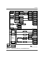
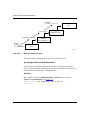
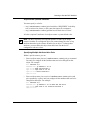
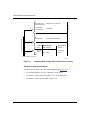
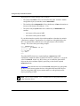
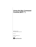
For example, using BCC commands, you can configure an Ethernet interface on
box (the root-level configurable object), IP on the Ethernet interface, and RIP on
that instance of IP (Figure 1-3). The sequence of commands you use to build this
configuration is:
bcc> ethernet slot 2 connector 1
ethernet/2/1> ip address 1.2.3.4
ip/1.2.3.4> rip
rip/1.2.3.4>
RIP
END:
rip/1.2.3.4>
IP
(address 1.2.3.4.)
Step 2:
ethernet/2/1> ip address 1.2.3.4
Ethernet
(slot 2, connector 1)
Box
(Root Level)
Step3:
ip 1.2.3.4> rip
START:
Step1:
bcc> ethernet slot 2 connector 1
BCC0003A
Figure 1-3.
Configuring an Ethernet Interface
Context -- Your working location within the BCC configuration tree. Just as a
UNIX file system has a current working directory within which you can add,
modify, or delete files, the BCC configuration system has a current working
context, within which you can add configurable objects, or modify or delete
configured objects.
The BCC always displays a context-sensitive prompt, indicating your current
working context or location within the configuration hierarchy.
Box -- The chassis for a network device.
1-6
115976-A Rev. A
Overview
Box-wide/Global Objects -- Objects that provide services uniformly to all slots of
a network device (box-wide); for example, TCP, SNMP, FTP, TFTP, NTP, and
TELNET. Some protocols, such as IP and OSPF have box-wide as well as
interface-specific objects. For example, IP contains BGP and OSPF, which in turn
contain other box-wide/globally configurable objects. When you add IP on an
interface, the BCC automatically finds, adds, and enables the box-wide/global IP
object with all default settings. The BCC can also enable any box-wide/global
objects that derive required attribute values from existing interface-level objects.
The root-level context, box, contains all box-wide/globally configurable objects.
Board -- Typically a logic or circuit board dedicated to a particular task, such as
providing central or distributed processing for a network device, or providing an
interface to a specific network transmission medium. Each board typically resides
in a slot in a network device. Some boards contain other boards such as an RMON
probe or a Data Collection Module (DCM).
Slot -- A location as well as a physical and electrical means for attaching modules
to logic and power connections internal to a network device. Each slot in a Bay
Networks device typically accommodates a processor or interface module (board)
of some type.
Line -- (1) A physical (and on some devices, logical) circuit identified typically by
means of a slot, connector, media type, and (where applicable, such as with TI/E1
facilities) a channel number. (2) The lowest common denominator for identifying
a packet data stream.
Connector -- The physical and electrical means to interconnect an interface
module in a network device directly or indirectly to a physical network medium.
Port -- (1) See connector. (2) On a network device or a user endstation, a logical
point of termination for data sent or received by a specific protocol or application.
For example, a UNIX workstation receives syslog messages from a remote device
at UDP logical port number 162.
Interface -- (1)A datalink/physical layer connection to a physical network
transmission medium. (2) Any packet stream of a particular type. The BCC
identifies each interface by combining its name (such as ethernet, token ring, fddi,
sync, or hssi), a slot number (where the interface resides physically in the device
chassis), and a connector number (on the module occupying the designated slot).
Certain devices, such as ASN routers, extend this terminology to include other
objects necessary for identifying a specific interface. An interface includes
media-specific driver software.
115976-A Rev. A
1-7
Using the Bay Command Console
Circuit -- Sometimes used by the BCC configuration system to denote (1) A
dedicated communication path; for example, a Permanent or Switched Virtual
Circuit (PVC or SVC) established between two hosts over a packet- or
cell-switched network, or over a dial or leased-line connection. (See also
connection.) (2) A specific packet stream processed by a network device. (3) A
driver for transporting a particular packet stream over a physical interface.
Connection -- (1) A path for reliable communication between two network
entities. The path can be physical or logical and the entities can be
hardware/software systems or subsystems and/or subsystems attached to the
network medium. (2) The path between two networking protocol modules that
provides reliable packet stream delivery service. (3) A temporary or permanently
“provisioned” path supporting end-to-end communication between two entities
on a network. Dial connections and SVCs are examples of temporary connections.
Leased-line connections and PVCs are examples of permanently provisioned
connections.
Protocol -- This is a configurable object that typically supports datalink-,
network-, transport-, session-, application-, or management-layer services on a
network device. Protocols may provide services box-wide (across all interface
slots), per slot (across all interface connectors on a specific slot), or per interface
(across all logical/virtual circuits associated with a specific connector and slot).
Network -- (1) A protocol-specific address that identifies the physical segment or
area where a specific station resides. (2) The network portion of an IP address.
(3) A group of computers, terminals, and other devices and the hardware and
software that enable them to exchange data and share resources over short or long
distances. (4) A group of nodes that communicate using a common channel. A
network can consist of any combination of LANs or WANs.
System Commands -- Enable you to perform system administration tasks from any
configuration context.
1-8
115976-A Rev. A
Overview
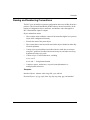
Naming and Numbering Conventions
The BCC uses one model to represent configuration data across all Bay Networks
products. This Network Data Model (NDM) enforces internal consistency in the
naming of configuration objects, attributes, and attribute values that appear as
BCC command line inputs or outputs.
Object and attribute names
•
Have a unique name within the context of the immediate higher-level (parent)
object in the configuration hierarchy
•
Exclude the name of the parent object
•
Have a name that is consistent with same/similar objects defined on other Bay
Networks platforms
•
Consist of one word (unabbreviated; abbreviated or made into an acronym
using BCC guidelines for abbreviations and acronyms; and where necessary,
hyphenated to make one word)
•
Consist of up to 32 ASCII characters, including
a to z, A to Z
0 to 9, and “-” for hyphenated names
•
Contain no spaces, underscores, or special (non-alphanumeric or
nondisplayable) characters
Examples:
Interface Objects: ethernet, token-ring, fddi, sync, and hssi
Protocol Objects: ip, bgp, ospf, telnet, ftp, tftp, ntp, snmp, ppp, and standard
115976-A Rev. A
1-9
Using the Bay Command Console
Attributes and Values (for IP on an ethernet interface):
group {ethernet/2/1}
state enabled
sub-protocols {arp/1.2.3.4/1 rip/1.2.3.4}
address 1.2.3.4
mask 255.0.0.0
assocaddr 0.0.0.0
cost 1
broadcast 0.0.0.0
mtu-discovery off
mask-reply off
all-subnet-broadcast off
address-resolution arp
proxy off
aging cacheoff
udp-checksum on
tr-end-station off
redirects on
cache-size 128
arp-mode client
arp-server-address 0x
arp-server-reg-interval clientdefault
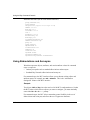
Using Abbreviations and Acronyms
Words that represent objects, attributes, and certain attribute values for command
input or output are
•
Industry-accepted words or standard abbreviations and acronyms
•
Standard Bay Networks abbreviations and acronyms
For command input, the BCC interface allows you to shorten existing object and
attribute names; for example, e or eth= ethernet. This is the “minimum to
distinguish” feature of the BCC interface.
Example:
Two objects, fddi and ftp exist at the root level of the BCC configuration tree. So that
the BCC knows which of these objects you want to configure, you must minimally
enter either fd or ft at the bcc> prompt.
For command output, the BCC allows somewhat greater flexibility in the use of
abbreviations and acronyms, and allows the use of uppercase characters.
1-10
115976-A Rev. A
Overview
Command Groups
The BCC supports a limited set of configuration and system commands in this
release. For more specific information on what you can (and cannot) configure
using the BCC, refer to the latest Release Notes or Read Me First publication.
Remaining chapters contain information on commands belonging to both groups.
115976-A Rev. A
1-11
Chapter 2
Learning to Use the BCC Interface
Entering and Exiting the BCC Interface
To access the BCC command line interface, first open a Technician Interface
session with the target device from
•
An ASCII terminal (for example, a VT-100 device) locally attached to the
console port of the router
•
A workstation or PC running terminal emulation software and locally
attached to the console port of the device
•
A remote workstation or PC running Telnet
Proceed as follows:
1.
To access the Technician Interface on a Bay Networks router, enter the
Manager command at the Login prompt that appears in your Telnet or
console display:
Login: Manager
Since the BCC enables you to perform device configuration, you cannot
access the BCC command line from a User login, which limits access to
device read-only commands. The Manager login entry allows you to enter any
Technician Interface or BCC commands.
2.
When you see the Technician Interface (console or Telnet) prompt, enter
the command bcc-trial to start the BCC interface.
router1> bcc-trial
bcc>
115976-A Rev. A
2-1
Using the Bay Command Console
3.
When you finish using the BCC, enter the exit command at any BCC
prompt. Exiting the BCC returns you to the Technician Interface prompt.
ethernet/2/1>
router1>
exit
If you need more detailed information on Technician Interface access, login, or
logout procedures, refer to Using Technician Interface Software.
The BCC supports normal (immediate) mode command entry. You enter one or
more commands after the BCC prompt, press Return, and the system executes the
commands.
About the BCC Configuration Hierarchy
The contents of the object class hierarchy (configuration tree) for each Bay
Networks device defines its set of configuration commands. The tree differs
somewhat from device to device, but the tree for every device occupies some
portion of the primary BCC Network Data Model. Within this model, you
configure similar objects in similar ways. For example, you can always configure
an ethernet interface on a Bay Networks device with the command:
bcc> ethernet <slot>/<connector>
The BCC configuration hierarchy is similar to that of a UNIX or DOS file system,
with its directories, subdirectories, and files.
Just as a file system has directories that contain other directories, the BCC
configuration system has (parent) objects that contain other (child) objects. Each
child object can in turn be a parent and contain other child objects.
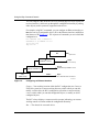
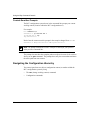
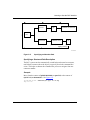
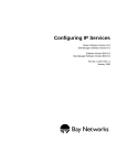
All objects in the BCC configuration system likewise exist in a tree hierarchy that
starts from a root level (implicitly, the <box> object) and branches to many other
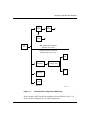
(child) object levels (Figure 2-1).
2-2
115976-A Rev. A
Learning to Use the BCC Interface
ip
(global)
arp
(global)
ospf
(global)
box
(root)
BOX-WIDE/GLOBAL OBJECTS
(Atttributes affect all slots)
INTERFACE-SPECIFIC OBJECTS
(Attributes affect only one slot)
ospf
(protocol)
ethernet/2/1
(interface)
ip address 1.2.3.4
(protocol)
arp
ethernet/2/1
(protocol)
(interface)
sync/3/1
(interface)
BCC0012A
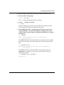
Figure 2-1.
Example BCC Configuration (BN Router)
In this example, OSPF and ARP are configured on (are children of) ip/1.2.3.4,
which in turn is configured on (is a child of) ethernet/2/1.
115976-A Rev. A
2-3
Using the Bay Command Console
Using the file system analogy:
•
The object named box (the container denoted by the root-level prompt, bcc>)
is like a root-level directory that “contains” the box-wide/global object ip and
an interface named ethernet/2/1.
•
The interface object ethernet/2/1 is like a subdirectory of box and contains an
instance of the protocol IP (address 1.2.3.4).
•
The protocol object ip/1.2.3.4 is like a subdirectory of ethernet/2/1 and
contains
-- An instance of the protocol OSPF (ospf/1.2.3.4)
-- An instance of the protocol ARP (arp/1.2.3.4/1)
In this example, the BCC automatically adds and enables the global IP and ARP
objects with default settings. The BCC tries to enable box-wide/global objects
related to interface-level objects you add to the device configuration.
Figure 2-1 shows that the root-level container “box” contains the box-wide/global
IP object, which in turn contains the box-wide/global ARP and OSPF objects.
The box-wide/global OSPF object contains other box-wide/global protocol
objects pertaining to OSPF.
Note: The root-level container, “box,” contains all box-wide/global objects for
a Bay Networks device.
2-4
115976-A Rev. A
Learning to Use the BCC Interface
Configuration Context
You describe the location of an object in the BCC configuration system by
specifying a path (sequence of containers) leading to that object, starting from the
root-level container, “box.” The path establishes the context for the object within
the BCC configuration tree.
Note: Context = The location of an object within the BCC configuration tree
for a device.
Displaying Context
In the BCC configuration system, you use the pwc (print working context)
command to show the location of the container (for example, a specific interface
or protocol) in which you are currently working.
To determine your current working context within the BCC configuration
hierarchy or tree for a device, you can
•
Enter the pwc (print working context) command at any prompt.
For example:
ip/192.168.4.1>
pwc
sync/3/2 ppp/3/2 ip/192.168.4.1
•
115976-A Rev. A
Display the full config/context path from
root (box) level to ip/192.168.4.1.
The path from root (box) level includes
the configured objects sync/3/2, ppp/3/2,
and ip/192.168.4.1.
Examine the current context-sensitive prompt (refer to the next section,
“Context-Sensitive Prompts”).
2-5
Using the Bay Command Console
Context-Sensitive Prompts
The BCC configuration system shows in the command line prompt your current
working context (location within the BCC configuration tree).
For example:
bcc> ethernet 2/1
ethernet/2/1> ip 192.168.150.1
ip/192.168.150.1> rip
rip/192.168.150.1>
Notice how the context-sensitive prompt in the example changed from bcc> to
ethernet/2/1> to ip/192.168.150.1> to rip/192.168.150.1>.
Note: The prompt contains the instance identifier of the object you specified
in the previous command line.
The prompt does not show the complete path to an object from root level as it does
when you use pwc command. The prompt shows only the context that terminates
the entire path from root context.
Navigating the Configuration Hierarchy
You can navigate from one object (configuration context) to another within the
BCC configuration system by using
2-6
•
The cwc (change working context) command
•
Configuration commands
115976-A Rev. A
Learning to Use the BCC Interface
Changing Context Levels
In the BCC configuration system, you use the cwc (change working context)
command to navigate to the context of an object, where you can
•
Add new objects.
•
Modify attributes of the current object.
•
Modify or delete objects contained by the current object.
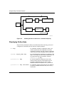
Moving Back One Level
Enter a cwc .. command to move back one level, from the context of the current
object to that of its parent object. For example, to move back one level, from the
context of ip/1.2.3.4 to the context of its parent, ethernet 2/1, proceed as follows:
ip/1.2.3.4> cwc ..
ethernet/2/1>
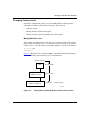
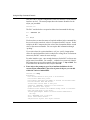
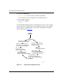
Figure 2-2 illustrates how entering two cwc .. commands incrementally changes
the current working context from rip/1.2.3.4 to ethernet/2/1.
(Starting Context:)
RIP
rip/1.2.3.4>cwc..
IP
(address 1.2.3.4.)
ip/1.2.3.4>cwc..
Ethernet
(slot 2, connector 1)
ethernet/2/1>
(Ending Context:)
BCC0007A
Figure 2-2.
115976-A Rev. A
Moving Back (Toward Root) One Context Level at a Time
2-7
Using the Bay Command Console
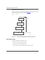
Moving Back to Root Context
To move back from your current working context to root (box) context, enter only
cwc at the command line prompt, as shown in Figure 2-3:
rip/1.2.3.4> cwc
bcc>
(Starting Context:)
RIP
rip/1.2.3.4>cwc
IP
(address 1.2.3.4.)
Ethernet
(slot 2, connector 1)
Box
bcc> (Root Context:)
BCC0008A
Figure 2-3.
Moving Immediately Back to the Root Context Level
Specifying Context
Using BCC configuration commands, you can
2-8
•
Move back to a previous (parent) context
•
Move forward to the next (child) context
•
Move from your current working context to any other context
115976-A Rev. A
Learning to Use the BCC Interface
Moving Back One or More Levels
To move from your current working context to the previous context (closer to
root), enter the object name and “REQUIRED” attribute values.
Example:
bcc> ethernet/2/1
ethernet/2/1> ip/1.2.3.4
ip/1.2.3.4> sync/3/1
sync/3/1>
In this case, the BCC searches back (toward root) automatically until it finds a
context (box) where the object you specified (in this case, sync/3/1) can exist.
The BCC enters the context of this object, and the command line prompt displays
your new location within the configuration tree.
Moving Forward One Level
To move forward from your current working context to the next branch context
level, enter the name of the object and values for any “REQUIRED” attributes of
that object (Figure 2-4).
Example:
bcc> ethernet/2/1
ethernet/2/1> ip/1.2.3.4
ip/1.2.3.4> rip
rip/1.2.3.4>
115976-A Rev. A
2-9
Using the Bay Command Console
(Terminating
Context:)
rip/1.2.3.4>
RIP
ip/1.2.3.4>rip
ethernet/2/1> ip/1.2.3.4
(Starting
Context:)
bcc> ethernet/2/1
IP
(address 1.2.3.4.)
Ethernet
(slot 2, connector 1)
Box
BCC0014A
Figure 2-4.
Moving Forward One Level
This is equivalent to changing directories in a UNIX file system.
Specifying an Absolute Path Description
You can specify an absolute path from the context of any object to any other
object. Specify the instance identifier of each object in the path from root level to
the desired level within the BCC configuration tree.
Example:
Move from the context of ip/192.168.33.66 (on sync/3/1) to the context of
rip/1.2.3.4 (on ethernet/2/1). See Figure 2-5.
ip/192.168.33.66>
rip/1.2.3.4>
2-10
box;ethernet/2/1;ip/1.2.3.4;rip
115976-A Rev. A
Learning to Use the BCC Interface
(Starting Context:)
sync/2/1
(interface)
ip address 192.168.33.68
ppp
(protocol)
(protocol)
box
ethernet/2/1
(interface)
ip address 1.2.3.4
(protocol)
rip
(protocol)
(Ending Context:)
BCC0009A
Figure 2-5.
Specifying an Absolute Path
Specifying a Shortened Path Description
The BCC system can also automatically search backward toward root context,
until it finds a context where the object you specify first in the command line
exists. This helps to shorten the command line you use to navigate from one
context to another.
Example:
Move from the context of ip/192.168.33.66 (on sync/3/1) to the context of
rip/1.2.3.4 (on ethernet/2/1). See Figure 2-6.
ip/192.168.33.66>
rip/1.2.3.4>
115976-A Rev. A
ethernet/2/1;ip/1.2.3.4;rip
2-11
Using the Bay Command Console
(Starting Context:)
ip address 192.168.33.68
ppp
sync/2/1
(protocol)
(interface)
(protocol)
box
ethernet/2/1
(interface)
ip address 1.2.3.4
(protocol)
rip
(protocol)
(Ending Context:)
BCC0010A
Figure 2-6.
Allowing the BCC to Search for a Context You Specify
Displaying Online Help
Enter the help command as follows for information about entering system and
configuration commands (the list includes example prompts):
bcc> help
For a definition of the BCC configuration model, most
common system-level and configuration commands,
configuration examples, and a list of objects configurable
in the root (“box”) context. Available at the root level only.
anyprompt> <object_name> help
For a list and definitions of attributes of an adjacent (child)
object. For example, from the context of ethernet/2/1, you
can invoke help for IP on that interface, as follows:
ethernet/2/1> ip help
ip/192.168.33.4>
help
For a list and definitions of attributes of the current
working context, plus a list of other objects (such as
protocols) configurable within the current context.
Available at all but the root (box or bcc>) context level.
ip/192.168.33.4>
help <attribute>
For a definition and list of legal values for the <attribute>
you specify. Available at all but the root (“box” or bcc>)
context level.
2-12
115976-A Rev. A
Learning to Use the BCC Interface
ip/192.168.33.4>
help *
For a definition and list of legal values for all attributes of
the current context. Available at all but the root (“box” or
bcc>) context level.
ip/192.168.33.4>
info
For a list of values assigned to the object configured in
the current context.
ip/192.168.33.4>
info <attribute>
For the value assigned to this <attribute> of the current
object or context.
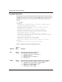
Getting Root-Level (System) Help
After entering help at the root-level (bcc>) prompt, you obtain
115976-A Rev. A
•
A description of the BCC configuration model
•
A list of common system commands and syntax necessary for configuration
and navigation
•
Basic examples of configuration syntax
•
A list of object names you can enter (add/modify/delete) within the root
context
2-13
Using the Bay Command Console
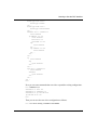
Example:
This is the root-level BCC help screen for a BN router.
### NOTE: Config commands make realtime changes to this device! ###
CONFIG MODEL: A tree, with each object at a specific level or context.
COMMANDS:
show config
help
help <attribute>
help *
<object> help
info
cwc
pwc
control+{p|n}
tic <command>
lso
exit
Show existing configuration in BCC syntax.
List attributes and objects configurable at this level.
Show range or values allowed for <attribute>.
List configurable attributes, values, and objects.
List attributes of <object>
List current attribute values for this object.
Go to root level (cwc) or previous level (cwc..)
Show full context, starting from root (bcc>) level.
Recall previous or next command(s).
Run a Technician Interface <command>.
List objects configured in this context.
Exit to Technician Interface.
OPERATIONS:
Configure interfaces, then add protocols.
* Configure a physical interface: <interface-type> <slot> <connector>
Example: fddi slot 3 connector 1 (or abbreviate) fd 3/1
* Configure a protocol on an interface (or) on another protocol:
<protocol> {<required_attribute> <value>} ...
Example:
ip address 192.168.3.4 (or abbreviate) ip 192.168.3.4
* Modify attribute values:
Example: cache-size 64
{<attribute> <new-value>} ...
* Disable, enable, or delete the current object:
disable|enable or delete
* Modify active config with commands from a file. source <volume>:<filename>
Example: source 2:bgpchg.bcc
### NOTE: Config commands make realtime changes to this device! ###
Configurable objects in this context:
ethernet tokenring sync hssi fddi
ip snmp ftp tftp telnet ntp
2-14
115976-A Rev. A
Learning to Use the BCC Interface
To return to this help screen at any time, enter:
> cwc
> help
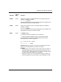
Getting Help for Configurable Objects and Attributes
By entering help at any prompt other than bcc>, you obtain a list of attributes and
objects you can configure (commands you can enter) within that context.
Example:
Get help for the context of IP (address 1.2.3.4) on ethernet/2/1:
ip/1.2.3.4> help
Attributes:
address: -REQUIRED- Address.
address-resolution: Specifies address resolution type.
aging: Specifies in seconds the host cache aging rate.
all-subnet-broadcast: Enables flooding of ASB packets out this intfc.
arp-mode: Indicates whether ATMARP is a client or server.
arp-server-address: Specifies the ATMARP server address.
arp-server-reg-interval: Specifies interval between refreshes.
assocaddr: Unnumbered Associated Ip Address.
broadcast: Specifies the IP broadcast address.
cache-size: Specifies the max number of cached routes.
cost: Specifies the RIP interface cost.
group: Parents of this object.
mask: Mask.
mask-reply: Enables ICMP address-mask-reply messages.
mtu-discovery: Enables the Reply MTU option on this interface.
name: The name given to the object.
proxy: Enables Proxy ARP on this interface.
redirects: Enables sending of ICMP redirects.
state: State enable disable.
sub-protocols: Objects this object contains.
tr-end-station: Enables TRES on this interface.
udp-checksum: Enables UDP checksuming on this interface.
Protocols:
rip ospf rdisc arp igmp
115976-A Rev. A
2-15
Using the Bay Command Console
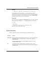
Getting Help for Configurable Attribute Values
Before modifying the value of an attribute, you can view its purpose and
allowable range or set of values by entering help <attribute_name> after the
context-sensitive prompt, for example:
ip/1.2.3.4> help aging
aging: Specifies in seconds the host cache aging rate
Legal value:{cacheoff cache120 cache180 cache240 cache300 cache600
cache900 cache1200}
ip/1.2.3.4>
To invoke a similar list for all attributes of an object, just enter help * after the
context-sensitive prompt, for example:
ip/1.2.3.4> help *
Attributes:
address: -REQUIRED- Address.
Legal value: <ip address>.
address-resolution: Specifies address resolution type.
Legal value: {arp ddn pdn inarp arpinarp none bfeddn probe arp
probe atmarp}
aging: Specifies in seconds the host cache aging rate.
Legal value:{cacheoff cache120 cache180 cache240 cache300
cache600 cache900 cache1200}
all-subnet-broadcast: Enables flooding of ASB packets out of
this interface.
Legal value: {on off}.
arp-mode: Indicates whether ATMARP is a client or server.
Legal value: {client server}.
arp-server-address: Specifies the ATMARP server address.
Legal value: <string>.
arp-server-reg-interval: Specifies interval between registration
refreshes.
Legal value: {clientdefault serverdefault}.
assocaddr: Unnumbered Associated Ip Address.
Legal value: <ip address>.
broadcast: Specifies the IP broadcast address.
.
.
.
sub-protocols: Objects this object contains.
Legal value: <object list>.
tr-end-station: Enables TRES on this interface.
Legal value: {on off}.
udp-checksum: Enables UDP checksuming on this interface.
Legal value: {on off}.
Protocols:
rip ospf rdisc arp igmp
2-16
115976-A Rev. A
Learning to Use the BCC Interface
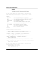
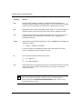
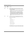
Displaying Assigned Attribute Values
To view currently assigned values for attributes of the current configuration
context, enter the info command at the prompt.
Example:
Get the values currently assigned to all attributes of IP (address 1.2.3.4) on
ethernet 2/1:
ip/1.2.3.4> info
group {ethernet/2/1}
state enabled
sub-protocols {arp/1.2.3.4/1}
address 1.2.3.4
mask 255.0.0.0
assocaddr 0.0.0.0
cost 1
broadcast 0.0.0.0
mtu-discovery off
mask-reply off
all-subnet-broadcast off
address-resolution arp
proxy off
aging cacheoff
udp-checksum on
tr-end-station off
redirects on
cache-size 128
arp-mode client
arp-server-address 0x
arp-server-reg-interval clientdefault
Or for a specific attribute, just enter info <attribute_name>, as follows:
ip/1.2.3.4>
cache-off
info aging
Two attributes, group and subprotocols have special meanings within the BCC
configuration model.
Group -- Identifies the parent of the current object. In the previous example, the
ethernet/2/1 object is the parent of the ip/1.2.3.4 object. Hence, the value of the
group attribute for ip/1.2.3.4 is ethernet/2/1. (Refer to Figure 2-1 to see this
relationship.)
115976-A Rev. A
2-17
Using the Bay Command Console
Subprotocols -- Just as a directory can contain files in a file system, an object in
the BCC configuration system can contain other objects. For example, ip/1.2.3.4
contains arp/1.2.3.4/1 and ospf/1.2.3.4. These two objects appear as
“subprotocols” of ip/1.2.3.4. (Refer to Figure 2-2 for an illustration of this
relationship.)
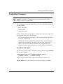
Displaying Configuration Data
You can use the show config command and the lso command to view Bay
Networks device configuration commands and data.
show config yields command-oriented output for
•
The total device configuration
•
The configuration of a specific context defined on the local device.
The lso command displays only configuration data (not commands) for a specific
context defined on the local device.
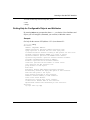
Displaying the Total Device Configuration
The show config command displays the entire device configuration as BCC
configuration syntax. This feature allows you to save the output of the show
config command as an ASCII file, and then source (merge) the contents of that
file directly into the active configuration of the same or another device at a later
time.
When you add configurable objects to an interface, the BCC automatically
navigates to a box-level context and adds any box-wide or global objects that it
can, based on the availability of values for the required attributes of those objects.
The output of show config includes commands that describe
2-18
•
Existing (configured) objects
•
New objects you add to, or modify within, the device configuration
•
Objects that BCC automatically added to the device configuration
•
Navigation (cwc ..) actions necessary to move to a working context
appropriate for configuring the next object, or to return to the root context
115976-A Rev. A
Learning to Use the BCC Interface
Example
bcc> ethernet slot 2 connector 1
ethernet/2/1> ip address 1.2.3.4
ip/1.2.3.4> rip
rip/1.2.3.4> sync slot 3 connector 1
sync/3/1> show config
box type 16896
mib-version 110001
build-location {Built in abc by def}
build-date {2.00 (32) Thurs Jan 16 15:11:41 EST 1997
verbose 0
board type 4608 slot 1
board-type atmcoc3mm
cwc ..
board type 162 slot 2
board-type qenf
cwc ..
board type 80 slot 3
board-type sync
cwc ..
board type 192 slot 4
board-type wffddi2m
cwc ..
board type 225 slot 5
board-type shssi
cwc ..
board type 176 slot 6
board-type dtok
cwc ..
board type 49 slot 7
board-type necfloppy
cwc ..
board type 5120 slot 8
board-type atmcds3
cwc ..
board type 4098 slot 9
board-type atmalcsonetmm
cwc ..
115976-A Rev. A
2-19
Using the Bay Command Console
ethernet slot 2 connector 1
state enabled
circuit-name E21
ip address 1.2.3.4
state enabled
mask 255.0.0.0
assocaddr 0.0.0.0
arp
state enabled
cwc ..
rip address 1.2.3.4
state enabled
cwc ..
cwc ..
cwc ..
ip
state enabled
arp
state enabled
cwc ..
cwc ..
sync slot 3 connector 1
state enabled
circuit-name S31
standard
state enabled
cwc ..
cwc ..
cwc ..
sync/3/1>
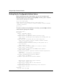
Displaying Objects within a Specific Context
You can view objects configured within a specific part of the BCC configuration
tree by using either the show config or lso (list objects) command.
Example 1: (show config)
Navigate to the context of IP (address 1.2.3.4) configured on ethernet 2/1 , and
then use the show config command to view that context in terms of BCC
configuration syntax, as follows:
2-20
115976-A Rev. A
Learning to Use the BCC Interface
bcc> ethernet slot 2 connector 1
ethernet/2/1> ip address 1.2.3.4
ip/1.2.3.4> show config ip/1.2.3.4
ip address 1.2.3.4
state enabled
mask 255.0.0.0
assocaddr 0.0.0.0
arp
state enabled
cwc ..
rip address 1.2.3.4
state enabled
cwc ..
cwc ..
ip/1.2.3.4>
Notice how the BCC shows the configuration of the working context, ip/1.2.3.4,
then inserts two cwc .. (change working context) commands to return to the same
working context.
Example 2: (lso)
Navigate to the context of IP (address 1.2.3.4) configured on ethernet 2/1, and
then use the lso command to view any instances of objects configured in that
context, as follows:
bcc> ethernet 2/1
ethernet/2/1> ip/1.2.3.4
ip/1.2.3.4> lso
arp/1.2.3.4/1 rip/1.2.3.4
ip/1.2.3.4>
Just as with show config, the output describes the same objects configured within
the context of IP (address 1.2.3.4), but not as reusable BCC configuration syntax.
(Use the lso command if you have no need for configuration syntax.)
115976-A Rev. A
2-21
Using the Bay Command Console
Displaying Binary Configuration Files as BCC Syntax
After booting the device from a binary configuration file, you can
•
Use the show config command to view the current device configuration in
readable BCC syntax.
•
Enter new configuration commands to override elements of the active device
configuration.
•
Again use the show config command to view the modified (or unmodified)
device configuration, and then save the file
-- As a BCC-readable and sourceable, ASCII configuration file.
-- As a binary configuration file, bootable on the same device, or on another
device.
Example:
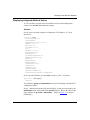
bcc> show config
box
type 16896 ;#bln
mib-version 110001
build-location {Built in <location>}
build-date {2.00 (32) Mon Dec 16 15:11:41 EST 1996}
verbose 0
board type 4608 slot 1
board-type atmcoc3mm
cwc ..
board type 162 slot 2
board-type qenf
cwc ..
board type 80 slot 3
board-type sync
cwc ..
board type 192 slot 4
board-type wffddi2m
cwc ..
board type 225 slot 5
board-type shssi
cwc ..
board type 176 slot 6
board-type dtok
cwc ..
board type 49 slot 7
board-type necfloppy
cwc ..
2-22
115976-A Rev. A
Learning to Use the BCC Interface
board type 5120 slot 8
board-type atmcds3
cwc ..
board type 4098 slot 9
board-type atmalcsonetmm
cwc ..
ethernet slot 2 connector 1
state enabled
ip address 1.2.3.4
state enabled
mask 255.0.0.0
assocaddr 0.0.0.0
arp
state enabled
cwc ..
rip address 1.2.3.4
state enabled
cwc ..
cwc ..
cwc ..
ip
state enabled
arp
state enabled
cwc ..
cwc ..
sync slot 3 connector 1
state enabled
standard
state enabled
cwc ..
cwc ..
cwc ..
bcc>
Now you can enter commands that override or expand the existing configuration:
bcc> ethernet 2/1
ethernet/2/1> bofl off
ethernet/2/1> ethernet 2/2
ethernet/2/2> ip 192.168.35.8
ip/192.168.35.8> cwc
bcc>
Then you can save the new device configuration as follows:
bcc> tic save config <volume>:<filename>
115976-A Rev. A
2-23
Using the Bay Command Console
This command saves the current device configuration as a bootable binary file, at
the location you specify.
Entering Commands
You can enter BCC configuration commands using basic (full), default, or
abbreviated syntax. In addition, command operators (also called methods)
enable you to perform certain operations within a configuration context more
efficiently.
Command Input Features
Command input features provided by the BCC enable you to
•
Use command recognition
•
Recall commands
•
Read commands from a file
•
Enter multiple commands per line
•
Continue a command line
•
Enter or interpret comments
•
Enter or interpret lists
Using Command Recognition
For configuration command input, you can shorten existing object and attribute
names (eth = ethernet). You must enter enough characters of an object or attribute
name for the BCC to recognize that name uniquely. Press Return to run any
command that contains shortened object or attribute names. This is the
“minimum to distinguish” feature of the BCC.
Example:
bcc> fd 5/1
fddi/5/1> cwc
bcc> ft
ftp>
2-24
115976-A Rev. A
Learning to Use the BCC Interface
Recalling Commands
The BCC supports a configurable command history buffer or list, from which you
can recall commands recently entered. Recall/re-enter commands from the history
list as follows:
Command
Purpose
Up-arrow key
or
Control + p
Recalls the previous command from the history
list
Down-arrow key
or
Control + n
Recalls the next command from the history list
The command history list contains up to 20 commands by default. You can
increase the number of commands in the history list to a maximum of 40 by
setting new values for the console and telnet attribute, history.
Example:
bcc> telnet
telnet> history 30
telnet> info history
30
telnet> cwc
bcc>
Reading (Sourcing) Commands from a File
You can use the source command to read (enter) BCC configuration and
navigation commands into the active device configuration.
Caution: The source command makes immediate changes to the active
device configuration.
The source command merges new configuration data from a file with existing
data in device memory. If the file you specify contains configuration commands
pertaining to existing objects, those commands dynamically overwrite the current
configuration.
115976-A Rev. A
2-25
Using the Bay Command Console
Syntax for the source command is as follows:
bcc> source <volume>:<filename>
Entering Multiple Commands per Line
To enter multiple commands in the same line, substitute a semicolon (;) wherever
you would press Return to terminate a command. For example, to configure RIP
on IP (address 1.2.3.4) on an ethernet interface (slot 2, connector 1), enter:
bcc> ethernet 2/1;ip address 1.2.3.4;rip
Continuing a Command Line
You can continue a command line by entering a backslash ( \ ) character at the end
of the current text line. The BCC treats characters on the next physical line as part
of the same BCC logical command line.
You must follow the escape character ( \ ) immediately by a newline (Return)
character. The BCC treats these two characters and any trailing whitespace as if
they were exactly one space. Until you press Return without a preceeding ( \ )
character, the BCC replaces the > symbol in the context-sensitive prompt with an
underscore ( _ ) character.
Example:
bcc> ethernet 2/1
ethernet/2/1> ip 192.32.150.1/255.255.255.0 \
ethernet/2/1_ cost 2 \
ethernet/2/1_ redirects on
ethernet/2/1>
Entering Comments
It is often helpful to add descriptive comments to a BCC configuration file. You
can enter comments in a BCC command line in the following format:
bcc> <command> ;# comment
or
bcc> #comment
bcc> <command>
2-26
115976-A Rev. A
Learning to Use the BCC Interface
Example:
bcc> board slot 1 type 162
;# 199.221.47.129
199.221.47.21
If you source an ASCII-formatted BCC configuration file that contains
comments, the active device configuration does not use or retain the comments.
For this reason, comments also do not appear in the output of a show config
command invoked on the active device configuration.
Using Lists
Some attributes such as group and sub-protocols take a list of values. Members
of the list are enclosed in braces ( { ... } ) and may span lines. For example:
bgp> info
group {ip}
state enabled
sub-protocols {peer/192.168.13.2/192.168.13.9/4
peer/192.168.13.2/192.168.13.8/4}
.
.
.
System Commands
The BCC supports the following commands within any configuration context:
Command
Function
show config
Displays the existing device configuration in BCC syntax. For more information on the
show config command, refer in this chapter to the earlier section, “Displaying
Configuration Data.”
For more information on Technician Interface show commands, refer to Using
Technician Interface Scripts.
lso
115976-A Rev. A
Lists all objects currently configured within the current BCC context. For more
information on the lso command, refer in this chapter to the earlier section, “Displaying
Configuration Data.”
2-27
Using the Bay Command Console
Command
Function
help
Displays system commands, operations, configurable objects (interfaces and
protocols), attribute definitions, and attribute values. For more information on the help
command, refer in this chapter to the earlier section, “Displaying On-Line Help.”
pwc
Displays the current working context within the BCC hierarchy. For more information on
the pwc command, refer in this chapter to the earlier section, “Displaying Context.”
cwc
Changes working context within the BCC configuration tree. For more information on
the cwc command, refer in this chapter to the earlier section, “Navigating the
Configuration Hierarchy.”
source
Reads in BCC commands saved previously to a file. The source command takes two
arguments, as follows:
bcc> source <volume>:<filename>
For more information on the source command, refer in this chapter to the earlier
section, “Reading (Sourcing) Commands from a File.”
tic
Run a Technician Interface command. For example:
bcc> tic compact 3:
or
bcc> tic show hardware
exit
Exits the BCC from any context level and returns to the Technician Interface command
line prompt. From the Technician Interface prompt, you can enter any Technician
Interface command.
Note: For information on any standard Technician Interface commands, refer
to the Using Technician Interface Software guide. For information on
Technician Interface show|monitor|enable|disable scripts, refer to Using
Technician Interface Scripts.
2-28
115976-A Rev. A
Learning to Use the BCC Interface
Configuration Commands
Caution: Configuration commands and source commands make realtime
changes to the device configuration.
This section describes how the BCC allows you to enter commands using any the
following formats:
•
Basic (full) syntax
•
Default syntax
•
Abbreviated syntax
All BCC syntax consists of object names, attribute names and values, and various
types of punctuation. Note in particular that
•
All object and attribute names appear as one word (hyphenated if necessary)
in the BCC command line.
•
Attributes have either a single value, or multiple values enclosed in braces
{x y z} in the command line. You either accept the system default value or
supply a value for each attribute associated with a configurable object.
•
Attributes and their values must appear as a pair in the same command line.
Using Basic (Full) Syntax
The basic or full syntax for BCC commands consists of the following {required}
and [optional] elements:
<object-name> [new|modify] {[<required_attribute>] <value> ... } ...
[ <attribute> <value>] ... [ <attribute> <value>]
The BCC requires input for any elements expressed here as boldface text.
<object_name> is the name of the object you want to configure or examine.
115976-A Rev. A
2-29
Using the Bay Command Console
The keyword new tells the BCC that you are adding a new object to the device
configuration. The keyword modify tells the BCC that you are modifying an
existing object in the device configuration. These keywords are optional in a BCC
command line because
•
The BCC assumes that you meant new if it does not find in the existing
configuration the object you specified.
•
The BCC assumes that you meant modify if it finds in the existing
configuration the object you specified.
{[<required_attribute>] <value>} is any attribute-value pair required to uniquely
identify the instance of the object you specified in the command line.
Note: You cannot change the value of an attribute that makes up the instance
identifier for an object. To change these attributes, you must delete the object,
then add it back into the device configuration with new values.
An object may have one or more required attributes. Using default syntax, you do
not have to enter the name of a required attribute; you enter only its value at the
proper location in the command line. (More information follows on BCC default
syntax.)
[<attribute> <value>] is any attribute-value pair you can optionally customize for
the object you specified in the command line.
For example, the full syntax you can use to configure an ethernet interface is
bcc> ethernet new slot 2 connector 1
Using Default Syntax
The following command is equivalent to ethernet slot 2 connector 1:
bcc> ethernet 2/1
ethernet is the object you want to add, modify, disable, (etc.).
2/1 are the two required arguments
2-30
115976-A Rev. A
Learning to Use the BCC Interface
With default syntax, the BCC expects the values for required attributes of
ethernet to occur in a specific sequence following the object name:
ethernet <slot>/<connector>
The next section describes how to use “probing” as a method to discover the
sequence in which the BCC expects you to enter values for the required attributes
of an object.
Discovering the Sequence of Required Attributes for an Object
You can always discover the sequence in which BCC expects you to enter the
values for required attributes of an object.
For example, to determine the sequence in which you must enter values for the
required attributes of sync interface, proceed as follows:
At the appropriate context, enter only the object name followed by a Return.
bcc> sync
ERROR: Required attribute "slot" was not specified for class: Sync.
The ERROR message reveals that the BCC was expecting a value for slot first.
Reenter the object name and the attribute-value pair requested by the BCC.
bcc> sync slot 3
ERROR: Required attribute "connector" was not specified for class: Sync.
The ERROR message reveals that the BCC was expecting a value for connector
next. Reenter the object name and the attribute-value pair requested by the BCC.
bcc> sync slot 3 connector 1
sync/3/1>
You defined the object sucessfully (as shown by the new context-sensitive
prompt), but you also discovered that the sequence for entering values for the
required attributes of an interface is <slot>/<connector>.
The ability to configure objects using only the values for required attributes is the
“minimum to configure” feature of the BCC.
115976-A Rev. A
2-31
Using the Bay Command Console
Using Abbreviated Syntax
You can abbreviate BCC commands in the following manner:
bcc> e 2/1
is the same as
bcc> ethernet slot 2 connector 1
or:
bcc> ethernet 2/1
The BCC completes or expands abbreviated names when you press Return. You
must enter enough characters for BCC to uniquely recognize the object you are
specifying. If you press Return before entering enough characters for BCC to
recognize the name of the object you want to add or modify, BCC returns an error
message:
bcc> invalid command name ”<string>“
Specifying Attribute Values
You must specify each attribute value in the form of a attribute-value pair. Each
pair is a command argument pertaining to the last object named earlier in the
command line.
For example, the following command disables the BOFL signal from connector 1
of the ethernet interface occupying slot 2 of a router:
bcc> ethernet 2/1 bofl disable
ethernet is the interface type and the actual BCC command word
2/1 represents the specific slot and connector location of the interface
bofl is the ethernet interface attribute you want to modify
disabled is the desired new value of the bofl attribute
bofl disable is the attribute-value pair
Any attributes you do not set (or cannot set, as in the case of read-only attributes)
maintain a value set by the system software.
2-32
115976-A Rev. A
Learning to Use the BCC Interface
Required and Optional Attributes
You must specify a value for
• Any [<attribute-name> <value>] pair classified as “REQUIRED” in the helptext, or enclosed in {braces} in the syntax description for a command.
• Any [<attribute-name> <value>] pair that has a default value of “None”
All other (“optional”) attributes of an object assume a system default value.
Note: The BCC frequently uses required attributes to make up the unique
instance identifier for a configured object. You cannot change the value of any
attribute that makes up the instance identifier for an object. To change these
attributes, you must delete the object, then add it back into the device
configuration with new values.
Specifying Multiple Attribute-Value Pairs
Within a specific context, you can
•
Enter an object name, plus one [<attribute-name> <value>] pair per command
line until you configure all the attributes that need to be changed for that
object. For example:
bcc> ethernet 2/1
ethernet/2/1> ip address 1.2.3.4
ip/1.2.3.4> mask 255.255.255.0
ip/1.2.3.4> ospf area 2.3.4.54
ospf/1.2.3.4> hello-interval 5
ospf/1.2.3.4>
•
Enter an object name, plus a series of <attribute-name> <value> pairs (each
pair separated by a space) until you configure all the attributes that need to be
changed for that object. For example:
bcc> ethernet 2/1
ethernet/2/1> ip address 1.2.3.4 mask 255.255.255.0
ip/1/2/3/4> ospf area 2.3.4.54 hello-interval 5
ospf/1.2.3.4>
115976-A Rev. A
2-33
Using the Bay Command Console
Command Operators
Command operators perform a named operation within the current or specified
configuration context. For example, entering the help operator within the context
of the ip (box-wide) service on a router invokes online help for that object, as
follows:
bcc> ip help
Attributes:
cache-timeout: Specifies interval for flushing forwarding tables.
classless: Enable classless routing.
forwarding: Specifies whether the router forwards IP traffic.
group: Parents of this object.
isp-mode: Specifies whether or not ISP Mode is Enabled.
max-policies: Specifies max policy rules per policy type.
mib-table: Specifies which MIB routing tables IP maintains.
name: The name given to the object.
rip-diameter: Specifies hop count RIP denotes as infinity.
route-filters: Specifies whether or not route filters are supported.
state: State enable disable.
sub-protocols: Objects this object contains.
subnet-zero: Allows the use of subnet zero.
time-to-live: Specifies starting value of Time-to-Live counter.
Protocols:
ospf bgp static-route tcp access-policy arp igmp
The BCC supports the following command operators:
Operator
Type of
Entry
Function
new
Implicit
or Explicit
Add a new object to the device configuration.
The following are equivalent examples:
bcc> ethernet new slot 2 connector 1
bcc> ethernet new 2/1
bcc> ethernet slot 2 connector 1
bcc> ethernet 2/1
modify
Implicit
or Explicit
Modify the value of an object existing in the current device configuration.
Each of the following example commands modify an ethernet object:
bcc> ethernet slot 2 connector 1 bofl enable
bcc> ethernet 2/1 modify bofl enable
bcc> ethernet 2/1 bofl enable
bcc> ethernet/2/1 bofl enable
2-34
115976-A Rev. A
Learning to Use the BCC Interface
Operator
Type of
Entry
disable
Explicit
Allows you to change the administrative state of a configured object from
“enabled” to “disabled,” as follows:
ip/1.2.3.4> disable
You can accomplish the same change by assigning the value “disabled” to the
state attribute of an object you want to disable.
enable
Explicit
Allows you to change the state of a configured object from “disabled” to
“enabled,” as follows:
ip/1.2.3.4> enable
You can accomplish the same change by assigning the value “enabled” to the
state attribute of an object you want to re-enable.
delete
Explicit
The delete operator
• Destroys an object you designate in the command line.
or
• Destroys the object identified in the BCC context-sensitive prompt
For example, both of the following commands destroy an IP interface
previously defined in a router configuration:
Function
bcc> ip 192.32.150.1 delete
or
ip/192.32.150.1>
delete
CAUTION: Deleting an object at one level of the configuration tree causes
the BCC to automatically delete any children of that object.
Examples:
• Deleting OSPF from the global IP context causes the BCC to delete any
dependent global services such as OSPF areas, accept policies, and
announce policies. Deleting OSPF from the global IP context also deletes
any instances of OSPF configured on any interface.
• Deleting an instance of IP on an interface also deletes any instances of
protocols configured on the same interface, such as ARP, RIP, or OSPF.
115976-A Rev. A
2-35
Using the Bay Command Console
Operator
Type of
Entry
help
Explicit
Displays descriptions of commands, attributes, and attribute values. BCC
help responses depend on where you enter the operator in a command line.
For example, entering help
• After the root (bcc>) prompt -- Invokes the list of system commands, plus
a list of protocols and line interfaces you can configure directly from that
prompt.
• After an object name (such as ip) -- Invokes the list of configurable
attributes associated with that object, plus a list of protocols you can
configure from that context. The word “REQUIRED” after the description
of any attribute means that you must supply a value for this attribute.
• Before an attribute name (such as “router-id”) -- Invokes the attribute
definition and options for setting the value of that attribute. (You can also
invoke the help operator using the wildcard character. Ex: sync/3/1>
help *)
info
Explicit
Lists the names and values currently assigned to attributes of the current
working context. For example, entering info after ip (from the box context)
invokes the following information:
Function
ip> info
group {box}
state enabled
forwarding forwarding
time-to-live 30
rip-diameter 15
cache-timeout dflt
mib-table route
subnet-zero disabled
classless disabled
max-policies default
route-filters enabled
isp-mode disabled
Use the info operator to check on your progress while configuring an object,
or to examine settings for the configuration of an object previously configured.
2-36
115976-A Rev. A
Learning to Use the BCC Interface
Editing Commands
You can edit BCC command lines using the following keystrokes:
115976-A Rev. A
Editing Function
Keystrokes
Move the cursor left
CONTROL + b or left-arrow key
Move the cursor right
CONTROL + f or right-arrow key
Delete the current line
CONTROL + u
Delete the word at the cursor location
CONTROL + w
Delete the character at the cursor location
CONTROL + d
Move the cursor to the beginning of the line
CONTROL + a
Move the cursor to the end of the line
CONTROL + e
Toggle insert mode
CONTROL + o
Backspace Delete
BKSP or DEL, or CONTROL + h
Interrupt
CONTROL + c
Start echo to the screen
CONTROL + q
Stop echo to the screen
CONTROL + s
Recall previous
CONTROL + p or up-arrow key
Recall next
CONTROL + n or down-arrow key
2-37
Chapter 3
Configuring a Network Device
This chapter describes how to use BCC commands to
•
Create a new configuration.
•
Modify an existing configuration.
•
Assign an alias name to any configured object.
•
Disable or enable a configured object.
•
Delete an object from the device configuration.
Configured Objects
Every object in the BCC configuration hierarchy has a prototype or template
“Class” object that has a name (such as “ip”) that you can enter at the BCC
prompt.
Each time you add a new object such as an interface or protocol to the device
configuration, you actually create a copy (an instance) of its class object,
customized with unique values for its required attributes. The object name,
combined with values for its required attributes, define a unique instance identifier
for that object.
Once you explicitly add an object to the device configuration, that object is
configured; a unique instance of that object now exists in the device configuration.
115976-A Rev. A
3-1
Using the Bay Command Console
Example:
To configure an Ethernet interface on slot 2, connector 1, of a BLN router, enter at
the command line prompt the name of the object (ethernet), followed by unique
values for its REQUIRED attributes (in this case, slot and connector). The BCC
creates a copy of the template (class object) for an ethernet interface and assigns
to the copy the unique instance identifier, ethernet/2/1.
bcc> ethernet slot 2 connector 1
ethernet/2/1>
The prompt displays the instance identifier for the new context.
When you enter the help command after the context-sensitive prompt, the BCC
displays a list of all objects configurable within that context. When you enter the
info command after the context-sensitive prompt, the BCC displays (after the
attribute name “subprotocols”) a list of all objects configured within that context.
The subprotocols list also displays each configured object by its unique instance
identifier.
Example:
Find out what configured objects exist within the context of IP (address 1.2.3.4)
on ethernet 2/1:
ip/1.2.3.4> info
group {ethernet/2/1}
state enabled
sub-protocols {arp/1.2.3.4/1 rip/1.2.3.4}
address 1.2.3.4
mask 255.0.0.0
.
.
.
.
.
.
In this example, instances of the protocol ARP and the protocol RIP are
configured within the context of ip/1.2.3.4, as follows:
arp/1.2.3.4/1 = ARP on ip/1.2.3.4; the BCC automatically appends the intenally
generated circuit number 1 to complete the unique instance identifier for this
object.
rip/1.2.3.4 = RIP on ip/1.2.3.4
Each object has its own requirements for unique instance identification.
3-2
115976-A Rev. A
Configuring a Network Device
Creating a New Configuration
You configure a Bay Networks device by defining a set of objects that collectively
define its behavior on a network. Each object has a set of attributes with values set
either by you or by the device software. Begin to configure a device starting at the
root (box) context. Define any interfaces and box-wide/global objects you need
on the device, and then follow the BCC configuration hierarchy to add
higher-layer protocol objects to each physical interface.
Figure 3-1 illustrates the following generic configuration sequence, which applies
to a variety of network devices:
115976-A Rev. A
1.
Open a Technician Interface session and start the BCC interface.
2.
Use BCC configuration commands to define the LAN or WAN interfaces
available on each slot and connector in the device.
3.
Use BCC configuration commands to add instances of network layer
(and higher-layer) protocols that you want on each interface.
4.
Enable any box-wide protocols not enabled automatically by the BCC
software during step 2 (for example, SNMP, TCP, FTP, and TELNET).
5.
Use the Technician Interface save command to save your configuration
as a bootable (binary) file on the device.
3-3
Using the Bay Command Console
Configuration Sequence
4.
Application layer
Presentation layer
(TELNET, TFTP, FTP, NTP)
Session layer
Transport layer
(TCP, UDP)
Network layer
(IP, RIP, OSPF, BGP, ARP))
S
N
M
P
3.
Datalink
layer
2.
Physical
layer
WAN interfaces
LAN interfaces
PPP, Standard
•Ethernet
•Token Ring
Sync, HSSI
1.
•FDDI
Root level (bcc>) prompt
BCC0011A
Figure 3-1.
Comparing BCC Configuration to OSI Protocol Layering
Example Configuration Problem:
Add the following objects to a BN router configuration (Figure 3-2):
3-4
•
An ethernet interface on slot 2, connector 1 of the <box>
•
An instance of the protocol IP (address 1.2.3.4) on ethernet/2/1
•
An instance of the protocol OSPF on ip/1.2.3.4
115976-A Rev. A
Configuring a Network Device
ip
(global)
arp
(global)
ospf
(global)
BOX-WIDE/GLOBAL OBJECTS
(Atttributes affect all slots)
INTERFACE-SPECIFIC OBJECTS
(Attributes affect only one slot)
ospf
(protocol)
ethernet/2/1
(interface)
ip address 1.2.3.4
(protocol)
box
arp
(protocol)
BCC0015A
Figure 3-2.
115976-A Rev. A
Example BCC Configuration
3-5
Using the Bay Command Console
Applying the file system analogy to this example:
•
The object named box is like a root-level directory that “contains” another
configurable object (an interface) named ethernet/2/1.
•
The interface object ethernet/2/1 is like a subdirectory of box and contains an
instance of the protocol IP (address 1.2.3.4).
•
The protocol object ip/1.2.3.4 is like a subdirectory of ethernet/2/1 and
contains
-- An instance of the protocol ARP
-- An instance of the protocol OSPF
If you add an interface-specific object with an attribute value that also satisfies
“minimum to configure” requirements of a related box-wide/global object, the
BCC can automatically enable the box-wide/global object with all default
settings. This occurs in the preceeding example.
bcc> ethernet 2/1
ethernet/2/1> ip address 1.2.3.4
ip/1.2.3.4> cwc
bcc> ip;ospf
ospf> cwc
bcc>
The global OSPF object has a required attribute, router-id, but OSPF
automatically adopts the address of the first IP interface (address 1.2.3.4) as the
value for router-id. In this way, BCC allows you to enable the global OSPF
object on the device without explicitly specifying a value for the required
router-id attribute.
Figure 3-2 shows that the root-level container box contains the box-wide/global
IP object, which in turn contains the box-wide/global ARP and OSPF objects.
The box-wide/global OSPF object contains other box-wide/global protocol
objects pertaining to OSPF.
Note: The root-level container, “box,” contains all box-wide/global objects for
a Bay Networks device.
3-6
115976-A Rev. A
Configuring a Network Device
To build this sample configuration, log in to the Technician Interface and
1.
Enter bcc-trial at the prompt.
router1>
bcc-trial
The bcc> prompt should appear after a brief delay.
2.
At the bcc> prompt, enter help.
bcc> help
The BCC displays top-level help screen. Read this information carefully.
Next, define physical interfaces installed on the device.
3.
Enter ethernet at the bcc> prompt and press Return to probe for any
required attributes. (For more information on probing, refer to the
section “Discovering the Sequence of Required Attributes for an Object”
in Chapter 2.)
bcc> ethernet
ERROR: Required attribute "slot" was not specified for
class: Ethernet.
The ERROR message reveals that the BCC was expecting a value for slot
first. Reenter the object name and the attribute-value pair requested by the
BCC.
bcc> ethernet slot 2
ERROR: Required attribute "connector" was not specified for
class: Ethernet.
The ERROR message reveals that the BCC was expecting a value for
connector next. Reenter the object name and the attribute-value pair
requested by the BCC.
bcc> ethernet slot 2 connector 1
ethernet/2/1>
115976-A Rev. A
3-7
Using the Bay Command Console
This moves BCC into the configuration context for connector 1 of the ethernet
interface on slot 2. The return prompt shows the instance identifier for the
object you just added:
ethernet/2/1>
The BCC would also have accepted an abbreviated command for this step:
bcc>
ethernet 2/1
or
bcc> e 2/1
You do not have to enter the names of required attributes in the command line,
but you do need to enter their values in a sequence that BCC expects. In this
example, the BCC interprets the first value as the slot number and the second
value as the connector number. You can acquire this information through
“probing.”
If you omit values for required attributes, or if you specify inappropriate
values for required attributes (in this example, the wrong slot or a nonexistent
connector), the BCC returns an error message.
For other interface types, enter enough characters for the BCC to discern one
object name from another. For example, within the box context of a Model
BLN router there are two object names with a first letter “f”: ftp and fddi. You
would abbreviate the names of these objects: ft and fd.
4.
Enter help at the prompt to get a list of attribute definitions for the
current object (ethernet/2/1), plus a list of protocol objects you can add
within the context of ethernet/2/1.
ethernet/2/1> help
Attributes:
bofl: Allows breath-of-life polls to be disabled.
bofl-retries: BOFL Retry Count.
bofl-timeout: Specifies the number of seconds for the BOFL timer.
bofl-tmo-divisor: BOFL TMO divisor.
circuit-name: Circuit Name of this port.
connector: -REQUIRED- connector of the interface.
group: Parents of this object.
hardware-filter: Enables the hardware bridge filter if available.
name: The name given to the object.
receive-queue-length: Number of receive buffers dedicated to
the chip.
slot: -REQUIRED- Slot of the port.
state: State enable disable.
sub-protocols: Objects this object contains.
3-8
115976-A Rev. A
Configuring a Network Device
transmit-queue-length: Number of transmit buffers dedicated to the
chip.
Protocols:
ip
5.
You need to add an instance of the protocol IP to the ethernet/2/1
interface at this time. Enter the following command to determine the
REQUIRED attributes of IP on an interface:
ethernet/2/1> ip help
Attributes:
address: -REQUIRED- Address.
address-resolution: Specifies address resolution type.
aging: Specifies in seconds the host cache aging rate.
all-subnet-broadcast: Enables flooding of ASB packets out
this interface
arp-mode: Indicates whether ATMARP is a client or server.
arp-server-address: Specifies the ATMARP server address.
arp-server-reg-interval: Specifies interval between refreshes.
assocaddr: Unnumbered Associated Ip Address.
broadcast: Specifies the IP broadcast address.
cache-size: Specifies the max number of cached routes.
cost: Specifies the RIP interface cost.
group: Parents of this object.
mask: Mask.
mask-reply: Enables ICMP address-mask-reply messages.
mtu-discovery: Enables the Reply MTU option on this interface.
name: The name given to the object.
proxy: Enables Proxy ARP on this interface.
redirects: Enables sending of ICMP redirects.
state: State enable disable.
sub-protocols: Objects this object contains.
tr-end-station: Enables TRES on this interface.
udp-checksum: Enables UDP checksuming on this interface.
Protocols:
rip ospf rdisc arp igmp
6.
Enter the name of the protocol, plus the name and value of its required
attribute, “address,” as follows:
ethernet/2/1> ip address 1.2.3.4
The prompt shows your new configuration context and the instance identifier
for that object.
ip/1.2.3.4>
115976-A Rev. A
3-9
Using the Bay Command Console
7.
From the context of ip/1.2.3.4, enter the following command to determine
the REQUIRED attributes of OSPF on an interface:
ip/1.2.3.4> ospf help
Attributes:
address: -REQUIRED- Address.
area: -REQUIRED- <no help available>
authentication-key: Specifies the Area's Authentication Key.
dead-interval: Specifies max seconds to declare neighbor down.
group: Parents of this object.
hello-interval: Specifies seconds between Hello packets.
metric: Specifies the interface's OSPF metric.
mtu: Specifies the MTU of OSPF packets.
name: The name given to the object.
poll-interval: Seconds between polls to inactive NBMA neighbor.
priority: Designated router election priority.
retransmission-interval: Specifies secs between OSPF
pkt retransmits.
state: State enable disable.
sub-protocols: Objects this object contains.
transit-delay: Specifies estimated seconds to transmit a packet.
type: Specifies the type of network.
Protocols:
<None>
8.
Enter the name of the protocol, plus the name and value of its required
attributes, as follows:
ip/1.2.3.4>
ospf area 0.0.0.0
Since OSPF on an interface adopts the address of the underlying IP object
(address 1.2.3.4), you supply a value for the OSPF area attribute only.
The prompt again shows your new working context and the instance identifier
for that object:
ospf/1.2.3.4>
9.
Enter info at the prompt to get a list of attribute values for the current
context.
ospf/1.2.3.4> info
group {ip/1.2.3.4}
state enabled
address 1.2.3.4
area 0.0.0.0
type broadcast
priority 1
transit-delay 1
retransmission-interval 5
3-10
115976-A Rev. A
Configuring a Network Device
hello-interval 10
dead-interval 40
poll-interval 120
metric 1
mtu 1
10. Try to change the value of the address attribute, as follows:
ospf/1.2.3.4>
address 2.3.4.5
ERROR: "address" attribute may not be specified by user
ospf/1.2.3.4>
Note: You cannot change the value of an attribute that makes up the instance
identifier for an object. To change these attributes, you must delete the object
and then add it back into the device configuration with new values.
11. Change the value for the OSPF type attribute. To determine the
allowable values for OSPF type, enter the help command, as follows:
ospf/1.2.3.4> help type
type: Specifies the type of network
Legal value: {broadcast nbma point-to-point pmp ietf}
12. Enter type and its new value, nbma
ospf/1.2.3.4>
type nbma
13. Enter info again to see the change you made in step 12.
ospf/1.2.3.4> info
group {ip/1.2.3.4}
state enabled
address 1.2.3.4
area 0.0.0.0
type nbma
priority 1
transit-delay 1
retransmission-interval 5
hello-interval 10
dead-interval 40
poll-interval 120
metric 1
mtu 1
115976-A Rev. A
3-11
Using the Bay Command Console
14. Save the configuration.
ospf/1.2.3.4> tic save config <volume>:<filename>
This command saves the configuration as a bootable binary file.
15. Exit the BCC interface.
ospf/1.2.3.4> exit
router1>
You may find that a helpful practice is to first diagram what you want to configure
in terms of the BCC configuration tree or hierarchy for the device. For example,
refer to Figure 1-2, and then follow a cycle of BCC configuration commands
similar to that shown in Figure 3-3.
START/
CONTINUE
Current
Prompt
Enter info to check new attribute
valuesin the current context.
Customize one or more attribute
values for the current object/context
(e.g.,ethernet/2/1> bofl disable).
Enter help for a list of attributes
and objects configurable in the
current/new context.
Enter an
object name
(For example, ethernet).
Enter info to check
attribute values assigned
in the new (current) context.
Re-enter <object name>
with any "REQUIRED"
attributes values (e.g.,ethernet 2/1).
Error message?
Enter <object_name> help
for a list of REQUIRED attributes
for the object you want to add.
Enter help<attribute>
to get the data type and values
allowed for each REQUIRED attribute.
BCC0013A
Figure 3-3.
3-12
Typical BCC Configuration Cycle
115976-A Rev. A
Configuring a Network Device
Modifying an Existing Configuration
This section describes by example how to modify an existing device
configuration. Specifically, the example requires you to
1.
Log in to a Bay Networks router, and start the BCC interface.
2.
Navigate to the context of OSPF on ip/1.2.3.4.
3.
Change the value of the OSPF type attribute from broadcast to ietf.
Log in to the Technician Interface, enter the bcc-trial command to start the BCC,
and then proceed as follows (refer to Figure 3-2 as needed):
1.
Navigate to the context of rip on ip/1.2.3.4 as follows:
bcc> ethernet/2/1;ip/1.2.3.4;ospf area 0.0.0.0
rip/1.2.3.4>
Note that each semicolon (;) serves as a Return in the command line.
2.
Enter type and press Return to get the value currently assigned to that
attribute of OSPF on an interface.
ospf/1.2.3.4> type
type broadcast
3.
Enter help type and press Return to get a list of legal values for that
attribute.
ospf/1.2.3.4> help type
type: Specifies the type of network
Legal value: {broadcast nbma pointtopoint pmp ietf}.
The BCC shows the legal values for type in the list format described in
Chapter 2.
4.
Change the value of the type attribute from broadcast to ietf by simply
entering a new attribute-value pair, as follows:
ospf/1.2.3.4>
5.
Verify the new value by repeating step 2.
ospf/1.2.3.4>
type ietf
115976-A Rev. A
type ietf
type
3-13
Using the Bay Command Console
6.
As an optional step, check the values currently assigned to all attributes
of OSPF on ethernet/2/1.
ospf/1.2.3.4> info
group {ip/1.2.3.4}
state enabled
address 1.2.3.4
area 0.0.0.0
type ietf
priority 1
transit-delay 1
retransmission-interval 5
hello-interval 10
dead-interval 40
poll-interval 120
metric 1
mtu 1
7.
Save the configuration.
ospf/1.2.3.4>
tic save config <volume>:<filename>
This command saves the configuration as a bootable binary file.
8.
Exit the BCC interface.
ospf/1.2.3.4>
exit
Sourcing Configuration Commands from a File
You can use the source command to read (enter) new syntax (BCC configuration
and navigation commands) into the active device configuration.
Caution: The source command makes real-time/immediate changes to the
active device configuration.
The source command takes new BCC configuration commands and data from a
file and merges the result of those commands with existing configuration data in
active device memory. If the file you specify in the source command contains
configuration commands pertaining to objects already defined on a device, the
file-based commands dynamically overwrite the configuration of those objects.
Syntax for the source command is as follows:
bcc> source <volume>:<filename>
3-14
115976-A Rev. A
Configuring a Network Device
Disabling a Configured Object
In most cases, the BCC automatically enables objects that you add to the device
configuration. However, you may need to disable an object to manage or
troubleshoot the device. Here is an example of how to disable an object (rip) on
ip/1.2.3.4:
1.
Specify the configuration context for the object you want to disable:
bcc> ethernet slot 2 connector 1
ethernet/2/1> ip 1.2.3.4
ip/1.2.3.4> rip
rip/1.2.3.4>
The BCC prompt indicates your current configuration context, before and
after each command.
2.
Disable RIP.
rip/1.2.3.4>
rip/1.2.3.4>
3.
disable
Verify RIP.
rip/1.2.3.4>
disabled
rip/1.2.3.4>
info state
Enabling a Configured Object
Using the previous example, proceed as follows to reenable an object (rip) on
ip/1.2.3.4:
1.
Specify the configuration context for rip:
bcc> ethernet slot 2 connector 1
ethernet/2/1> ip 1.2.3.4
ip/1.2.3.4> rip
rip/1.2.3.4>
The BCC prompt indicates your current configuration context, before and
after each command.
2.
Reenable RIP.
rip/1.2.3.4>
rip/1.2.3.4>
115976-A Rev. A
enable
3-15
Using the Bay Command Console
3.
Verify RIP.
rip/1.2.3.4>
enabled
rip/1.2.3.4>
info state
Deleting a Configured Object
Because of the tree hierarchy, objects on higher branches of the tree depend on the
state (and existence) of objects closer to the root of the tree. Deleting an object
also deletes any (child) objects contained by that (parent) object. This is
analogous to deleting a main directory in a UNIX file system, where deleting a
main directory also deletes all of its subdirectories.
When you delete an object in the device configuration, the BCC automatically
“cleans up” (deletes) any dependent objects.
Using the previous example, proceed as follows to delete RIP from IP 1.2.3.4:
1.
Specify the configuration context for the object you want to delete:
bcc> ethernet slot 2 connector 1
ethernet/2/1> ip 1.2.3.4
ip/1.2.3.4> rip
rip/1.2.3.4>
or
bcc>
2.
ethernet/2/1;ip/1.2.3.4;rip
Delete RIP.
rip/1.2.3.4>
ip/1.2.3.4>
3.
delete
Verify RIP.
ip/1.2.3.4> info sub-protocols
{arp/1.2.3.4/1}
ip/1.2.3.4>
Note that the instance of rip/1.2.3.4 does not appear as a configured object in the
info list for ip/1.2.3.4.
Every object configurable through the BCC has a sub-protocols attribute, the
value of which is a list of objects configured on (or within) the current context
(ip/1.2.3.4, in this case). If you delete an object from that context, the
sub-protocols attribute acquires a new value, {arp/1.2.3.4/1} in this example.
3-16
115976-A Rev. A
Configuring a Network Device
Configuration Command Responses
The BCC configuration system completes the configuration task you entered
unless there is a syntax error, semantics error, or completion error. You can display
and verify the configuration by entering the info or show config commands.
The BCC configuration system may in certain circumstances be unable to
complete a configuration command; this is a completion error. In this and other
cases, the BCC returns an appropriate error message to the command line prompt.
115976-A Rev. A
3-17
Chapter 4
Examples
This chapter contains examples of BCC command sequences that
115976-A Rev. A
•
Identify link modules residing in a device.
•
Configure an ethernet interface with IP, ARP, and RIP.
•
Configure a HSSI interface with IP.
•
Configure a token ring interface with IP and RIP.
•
Configure PPP on a Sync Interface.
•
Configure an FDDI interface with IP and RIP.
•
Configure OSPF and BGP.
•
Configure TELNET, FTP, SNMP, and NTP.
4-1
Using the Bay Command Console
Identifying Link Modules Residing in a Device
Before you begin configuring a device, you can check the complement of boards
locally installed, as shown in this example:
Prompts, Commands, and Responses
Comments
router1> bcc-trial
Enter BCC mode from the Technician
Interface prompt.
bcc> lso
board/1 board/2
List objects configured on the device. You
need to determine what kind of boards are
installed in the device.
bcc> board/1
board/1> info
group {box}
type 162
slot 1
board-type qenf
Go to the context of board/1.
Display the values currently assigned to the
board/1 object.
The value of the “type” attribute (162)
represents the type of link module (quad
ethernet ). (Refer to the Release Notes for
the latest information on how to convert
board type numbers and abbreviations to
module descriptions.)
The interface identifiers corresponding to
board/1 are ethernet/1/1, ethernet/1/2,
ethernet/1/3, and ethernet/1/4.
board/1> cwc ..
Go back to the previous level in the
configuration tree. (This is similar to the
cd .. command on a UNIX system.)
bcc> exit
Exit BCC and return to the Technician
Interface prompt.
4-2
115976-A Rev. A
Examples
Configuring an Ethernet Interface with IP, ARP, and RIP
You can configure (add/customize) a physical interface and add protocols to that
interface as shown in the following example:
Prompts, Commands, and Responses
Comments
bcc> e 1/1
Add to the device configuration an ethernet
interface on slot 1, connector 1. (Enter the
command in abbreviated default syntax.)
ethernet/1/1> bofl disable
Change the value of the bofl attribute for
ethernet/1/1 from enabled to disabled.
ethernet/1/1> info
Verify the new values for bofl and other
attributes of ethernet/1/1.
group {box}
The “parent” or previous context level in the
tree is box.
state enabled
slot 1
connector 1
bofl disable
The BofL mechanism for ethernet /1/1 has
been disabled.
bofl-timeout 5
hardware-filter disable.
transmit-queue-length 0.
receive-queue-length 0
bofl-retries 5.
bofl-tmo-divisor1.
ethernet/1/1> ip address 192.168.1.1
Add IP (address 192.168.1.1) to ethernet/1/1.
IP uses the natural mask value set by the
system.
ip/192.168.1.1> arp
Enable ARP on ip/192.168.1.1.
arp/192.168.1.1/1> rip
Enable RIP on ip/192.168.1.1.
rip/192.168.1.1> info
Verify values currently assigned to the
configurable attributes of RIP.
115976-A Rev. A
4-3
Using the Bay Command Console
Prompts, Commands, and Responses
Comments
group {ip/192.168.1.1}
state enabled
address 192.168.1.1
supply enable
listen enable
default-supply disable
default-listen disable
mode poisoned
time-to-live 1
version rip1
authentication-type none
authentication 0x
rip/192.168.1.1> cwc ..
Go back to the previous level in the
configuration tree.
ip/192.168.1.1>
Configuring a HSSI Port with IP
To configure a HSSI port with IP, you must also specify a WAN protocol such as
Standard, as shown in this example.
Prompts, Commands, and Responses
Comments
bcc> hssi 5/1
Define (add) the HSSI interface on slot 5,
connector 1
hssi/5/1> info
Check values currently assigned to this object.
group {box}
state enabled
sub-protocols {standard/5/1}
circuit-name H51
slot 5
connector 1
bofl enabled
4-4
115976-A Rev. A
Examples
Prompts, Commands, and Responses
Comments
bofl-timeout 1
mtu 4608
media dsthree
external-clock-speed 46359642
crc-size crc32bit
internal-clock-test disabled
bofl-number 5
bofl-length 100
receive-queue-length 0
transmit-queue-length 0
carrier-delay 0
hssi/5/1> help
Discover what you can configure next in this
context.
Attributes:
bofl: Allows the breath-of-life polls to be disabled.
bofl-length: Specifies the breath of life packet
length.
bofl-number: Number of breath of life packets per
breath of life.
bofl-timeout: Specifies the number of seconds for
the BOFL timer.
carrier-delay: Number of seconds after Carrier
Loss for Loss State.
circuit-name: Circuit Name of this port.
connector: -REQUIRED- connector of the interface.
crc-size: Specifies the CRC size.
external-clock-speed: Specifies the external clock
speed.
group: Parents of this object.
internal-clock-test: Specifies the clock source for
the interface.
media: Specifies the media MIB selection.
mtu: Specifies the interface's Max Transmit Unit.
name: The name given to the object.
115976-A Rev. A
4-5
Using the Bay Command Console
Prompts, Commands, and Responses
Comments
receive-queue-length: Number of receive buffers
dedicated to the chip.
slot: -REQUIRED- Slot of the port.
state: State enable disable.
sub-protocols: Objects this object contains.
transmit-queue-length: Number of transmit buffers
dedicated to the chip.
Protocols:
ppp standard
hssi/5/1> standard
Use Standard as the WAN protocol.
standard/5/1> ip 192.168.12.1
Add an instance of IP (address 192.168.17.1) to
the HSSI port.
ip/192.168.17.1>
Configuring a Token Ring Interface with IP and RIP
You can configure IP and RIP on a token ring interface with just three
configuration commands, as shown in this example. (The example also includes
help and cwc commands.)
Prompts, Commands, and Responses
Comments
ip/192.168.1.1> tokenring 6/1
Add to the device configuration a token ring
interface on slot 6, connector 1.
tokenring/6/1> help speed
Show the configurable values for ring speed.
speed: 16Meg or 4Meg token ring speed
Legal value: {4Meg , 16Meg
tokenring/6/1> speed 4meg
Set the speed of the token ring interface to
4 Mbps.
tokenring/6/1> help
Discover what you can configure next in this
context.
Attributes:
circuit-name: Circuit Name of this port
connector: -REQUIRED- connector of the interface.
group: Parents of this object.
4-6
115976-A Rev. A
Examples
Prompts, Commands, and Responses
Comments
name: The name given to the object
slot: -REQUIRED- Slot of the port.
speed: 16Meg or 4Meg token ring speed.
state: State enable disable.
sub-protocols: Objects this object contains.
Protocols:
ip
You can configure attributes of tokenring/6/1 or
add an instance of ip and/or ipx on the interface.
tokenring/6/1> ip address 192.168.2.1
Add IP (address 192.168.2.1) to tokenring 6/1.
ip/192.168.2.1> rip
Enable RIP on ip/192.168.2.1.
rip/192.168.2.1> cwc
Go back to the root-level (bcc> ) prompt.
bcc>
Configuring PPP, IP, and an Adjacent Host (Sync Interface)
This example configures PPP and IP on a synchronous interface, and then defines
a single adjacent host on the same interface.
Prompts, Commands, and Responses
Comments
rip/3.3.3.3> sync 3/2
Add to the device configuration a
synchronous interface on slot 3, connector
2.
sync/3/2> ppp
Add PPP to sync/3/2.
ppp/3/2> help
Discover what you can configure next in this
context.
Attributes:
group: Parents of this object.
name: The name given to the object.
sub-protocols: Objects this object contains.
Protocols:
ip line
115976-A Rev. A
You can configure attributes of PPP, or you
can add an IP or Line object to ppp/3/2.
4-7
Using the Bay Command Console
Prompts, Commands, and Responses
Comments
rip/3.3.3.3> sync 3/2
Add to the device configuration a
synchronous interface on slot 3, connector
2.
ppp/3/2> ip address 192.168.4.1 adjhost 192.168.4.2
Add IP (address192.168.4.1) and an
adjacent host (address 192.168.4.2) to
ppp/3/2.
ip/192.168.4.1> pwc
Display the full config/context path from root
level to ip/192.168.4.1.
sync/3/2 ppp/3/2 ip/192.168.4.1
The path branches from root level to
sync/3/2, ppp/3/2, and finally
ip/192.168.4.1.
Configuring a FDDI Interface with IP and RIP
This example includes an attempt to change the address assigned to IP on a FDDI
interface. Note the BCC responses to this attempt, and note the corrective action.
Prompts, Commands, and Responses
Comments
ip/192.168.4.1> fddi 4/1
Add to the device configuration a FDDI
interface on slot 4, connector 1.
fddi/4/1> ip 192.168.5.1
Add IP (address 192.168.5.1) to fddi/4/1.
ip/192.168.5.1> rip
Enable RIP on ip/192.168.5.1.
rip/192.168.5.1> pwc
Display the full path from root level to
rip/192.168.5.1.
fddi/4/1 ip/192.168.5.1 rip/192.168.5.1
The path branches from root level to
fddi/4/1, ip/192.168.5.1, and then to
rip/192.168.5.1.
rip/192.168.5.1> info
Verify values currently assigned to the
configurable attributes of RIP on
ip/192.168.5.1.
group {ip/192.168.5.1}
The “parent” or previous context level in the
tree is ip/192.168.5.1.
state enabled
address 192.168.5.1
This is the IP address assigned to this fddi
interface.
supply enable
4-8
115976-A Rev. A
Examples
Prompts, Commands, and Responses
Comments
listen enable
default-supply disable
default-listen disable
mode poisoned
time-to-live 1
version rip1
authentication-type none
authentication 0x
rip192.168.5.1> cwc ..
Go back to the previous level in the
configuration tree.
ip/192.168.5.1> address 192.168.5.2
Try to change the ip address of the
interface.
ERROR: "address" attribute may not be modified
The address cannot be changed because it
is a REQUIRED attribute and part of the
instance identifier for IP on an interface.
ip/192.168.5.1> delete
To change the address assigned to this
instance of IP, you must delete the instance
and add a new instance of IP with a new
address on fddi/4/1. When you delete IP
from an interface, the BCC also deletes RIP
from that interface.
fddi/4/1> ip 192.168.5.2
Add a new instance of IP (with a new
address) to fddi/4/1.
ip/192.168.5.2> exit
Exit the BCC and return to the Technician
Interface prompt.
115976-A Rev. A
4-9
Using the Bay Command Console
Configuring OSPF and BGP
This example shows how to
•
Add two OSPF areas
•
Add OSPF to interfaces configured on the device
•
Configure BGP (global/box-wide)
•
Add one BGP peer
•
Add two BGP policy filters
Prompts, Commands, and Responses
Comments
bcc> ip
Add the global IP object to the device
configuration.
ip> virtual
Add a virtual IP interface for the OSPF
and/or BGP router-id. (You could add a
physical interface instead of a virtual
interface.) In this case, the BCC
automatically searches backward toward
root to find a context suitable for configuring
a virtual interface.
virtual> ip address 192.168.100.1
Add IP (address 192.168.100.1) to the
virtual interface.
ip/192.168.100.1> cwc
Go back to the root-level (bcc> ) prompt.
bcc> ip
Return to the context of global IP.
ip> ospf
Add OSPF to the global IP object.
ospf> help
Discover what you can configure next in this
context.
Attributes:
as-boundary-router: Converts all non-OSPF routers into
OSPF.
as-default-tag: Specifies method of generating OSPF
external tags.
ase-metric-support: Advertise route weight as metric in
ASE Type 2.
backup-log-mask: Log level for backup OSPF log messages.
backup-lsdb: Enables backup of OSPF soloist's LSDB.
group: Parents of this object.
4-10
115976-A Rev. A
Examples
Prompts, Commands, and Responses
Comments
holddown: Max seconds between running djikstra algorithm.
log-mask: Log level for OSPF log messages.
max-equal-path: Maximum number of equal cost paths.
name: The name given to the object.
router-id: -REQUIRED- <no help available>
slot-mask: List of slots that can run the OSPF soloist.
state: State enable disable.
sub-protocols: Objects this object contains.
Protocols:
area accept announce
You can configure attributes of the global
OSPF object, or you can add an OSPF area,
accept policy, or announce policy.
ospf> as-boundary-router true
Enable the Autonomous System (AS)
boundary router to receive external RIP
routes.
ospf> area 0.0.0.0
Add an ospf area (number 0.0.0.0) to the
global OSPF object.
area/0.0.0.0> info
Verify the values currently assigned to
attributes of ospf area 0.0.0.0.
group {ospf}
state enabled
area-id 0.0.0.0
authentication-type nopassword
stub true
stub-metric 1
import-summaries true
area/0.0.0.0> area 0.0.0.1
Add another OSPF area (number 0.0.0.1) to
the global OSPF object.
area/0.0.0.1> info
Verify the values currently assigned to
attributes of ospf area 0.0.0.1.
group {ospf}
state enabled
area-id 0.0.0.1
authentication-type nopassword
115976-A Rev. A
4-11
Using the Bay Command Console
Prompts, Commands, and Responses
Comments
stub true
stub-metric 1
import-summaries true
area/0.0.0.1> cwc ..
Go back to the previous level in the
configuration tree.
ospf> info
Verify the values currently assigned to
attributes of the global OSPF object.
group {ip}
state enabled
sub-protocols {area/0.0.0.0 area/0.0.0.1}
Both areas appear as “subprotocols” of
OSPF.
router-id 192.168.100.1
The IP adress assigned earlier to the virtual
interface also serves as the OSPF router ID.
as-boundary-router true
The AS boundary router is enabled.
holddown 1
slot-mask 4294705152
ase-metric-support disabled
backup-lsdb disabled
log-mask 287
backup-log-mask 0
as-default-tag zero
max-equal-path 1
ospf> e 2/2
Add to the device configuration a new
ethernet interface on slot 2, connector 2.
The BCC searches back toward root to find
the context (box) for an ethernet interface.
ethernet/2/2> ip 192.168.8.1
Add IP to the interface.
ip/192.168.8.1> ospf area 0.0.0.0
Add OSPF to ip/192.168.8.1, for area
0.0.0.0.
ospf/192.168.8.1> info
Verify the values currently assigned to
attributes of ospf/192.168.8.1.
group {ip/192.168.8.1}
state enabled
address 192.168.8.1
4-12
115976-A Rev. A
Examples
Prompts, Commands, and Responses
Comments
area 0.0.0.0
type broadcast
priority 1
transit-delay 1
retransmission-interval 5
hello-interval 10
dead-interval 40
poll-interval 120
metric 1
mtu 1
ospf/192.168.8.1> e 2/3
Add to the device configuration a new
ethernet interface on slot 2, connector 3.
ethernet/2/3> ip 192.168.9.1
Add IP (address 192.168.9.1) to
ethernet/2/3.
ip/192.168.9.1> ospf area 0.0.0.1
Add ospf to ip/192.168.9.1, for area 0.0.0.1
ospf/192.168.9.1> cwc ..
Go back to the previous level in the
configuration tree.
ip/192.168.9.1> arp
Enable ARP on ip/192.168.9.1.
arp/192.168.9.1/4> info
Verify the values currently assigned to
attributes of arp/192.168.9.1/4.
group {ip/192.168.9.1}
state enabled
address 192.168.9.1
cctnum 8
ip/192.168.9.1> cwc
Go back to the root-level (bcc> ) prompt.
bcc> sync 3/3
Add to the device configuration a
synchronous interface.
sync/3/3> ppp
Add PPP to sync/3/3.
ppp/3/3> ip address 192.168.10.1 adjhost 192.168.10.2
Add IP (address 192.168.10.1) and an
adjacent host (address 192.168.10.2) to
ppp/3/3.
ip/192.168.10.1> cwc
Return to the bcc> prompt, box context.
bcc> ip
Return to the context of global IP.
ip> bgp
Add global BGP to global IP.
115976-A Rev. A
4-13
Using the Bay Command Console
Prompts, Commands, and Responses
Comments
bgp> help
Discover what you can configure next in this
context.
Attributes:
group: Parents of this object.
inject-time: Interval EBGP routes are inserted in routing
table.
intra-as-routing: Specifies whether EBGP routes are
imported into IGP.
local-as: AS of the local router.
max-redundant-routes: Maximum number of duplicate
routes.
multi-hop: Allows EBGP peers not to be directly connected.
name: The name given to the object.
redistribute-protocols: Specifies if non-BGP external routes
are propogated.
redundant-connection: Allows multiple connections between
BGP peers.
route-server-cluster: Specifies the route server cluster.
router-id: -REQUIRED- <no help available>
rs-request: Specifies whether alternate routes will be
requested.
rs-topology: Specifies configuration of the route server.
slot-list: <no help available>
slot-mask: <no help available>
state: State enable disable.
sub-protocols: Objects this object contains.
subnet-aggregation: Enables aggregation of non-BGP
subnets for advertisement.
Protocols:
peer accept announce
bgp> local-as 13
Set the AS number to 13.
bgp> peer local 192.168.10.1 remote 192.168.10.2 as 14
Specify the bgp peer (local address
192.168.10.1, remote address
192.168.10.2) in AS 14.
4-14
115976-A Rev. A
Examples
Prompts, Commands, and Responses
Comments
peer/192.168.10.1/192.168.10.2/14> info
Verify the values currently assigned to BGP
peer/192.168.10.1/192.168.10.2/14.
group {bgp}
state enabled
local 192.168.10.1
remote 192.168.10.2
as 14
min-version bgp4
max-version bgp4
advertise-time 30
retry 120
holddown 90
keepalive 30
path-table enabled
min-originate-time 15
max-update-size 800
route-echo disabled
discard-duplicates disabled
rs-mode none
rs-identifier 0
delay 30
peer/192.168.10.1/192.168.10.2/14> cwc ..
Go back to the previous level in the
configuration tree.
bgp> announce "announce all"
Add a BGP announce policy called
“annouce all”.
announce/announce all> to-as 14
Announce all networks to AS 14.
to-as/14/announce all> info
Verify the values currently assigned to
attributes of to-as/14/announce all.
group {"announce/announce all"}
asnumber 14
polname announce all
115976-A Rev. A
The policy name is “announce all.”
4-15
Using the Bay Command Console
Prompts, Commands, and Responses
Comments
to-as/14/announce all> accept "accept-192.168.0.0"
Add a BGP accept policy called
“accept-192.168.0.0”.
accept/accept-192.168.0.0> action accept
accept/accept-192.168.0.0> from-as 14
Accept routes from AS 14.
from-as/14/accept-192.168.0.0> cwc ..
Go back to the previous level in the
configuration tree. Specify the addresses
you want to accept from AS 14.
accept/accept-192.168.0.0> network address 192.168.0.0
mask 255.255.0.0 match range
network/accept-192.168.0.0/192.168.0.0/255.255.0.0/Range
> info
Verify the values currently assigned to this
context.
group {accept/accept-192.168.0.0}
address 192.168.0.0
Only addresses starting with 192.168.x.x will
be accepted.
mask 255.255.0.0
match Range
polname accept-192.168.0.0
network/accept-192.168.0.0/192.168.0.0/255.255.0.0/Range
> cwc ..
Go back to the previous level in the
configuration tree.
accept/accept-192.168.0.0> info
Verify the values currently assigned to
attributes of the accept policy
accept/accept-192.168.0.0.
group {bgp}
state enabled
sub-protocols {from-as/14/accept-192.168.0.0 network/
accept-192.168.0.0/192.168.0.0/255.255.0.0/Range}
polname accept-192.168.0.0
action accept
preference 1
precedence 0
origin any
local-preference 0
bgp-preference 1
4-16
115976-A Rev. A
Examples
Prompts, Commands, and Responses
Comments
as-weight-class class1
as-path {}
accept/accept-192.168.0.0> cwc
Go back to the root-level (bcc> ) prompt.
Configuring TELNET, FTP, SNMP, and NTP
This is an example of how to configure four global/box-wide services on a BN
router. These are typical, initial configuration tasks.
Prompts, Commands, and Responses
Comments
bcc> telnet
Add the global telnet protocol
to the device configuration.
telnet> client
Add TELNET client capability
to global TELNET.
client> snmp
Add snmp global context
snmp> help
Discover what you can
configure next in this context.
Attributes:
authentication-traps: Sends trap for sets from false Mgr or Community.
group: Parents of this object.
lock: Allows the locking mechanism to be disabled.
lock-address: Allows the lock address to be cleared.
lock-timeout: Max number of seconds the agent can be locked.
name: The name given to the object.
state: State enable disable.
sub-protocols: Objects this object contains.
type-of-service: Allows the agent to use reliable UDP datagrams.
Protocols:
community trap-entity trap-event
snmp> community public
Specify an SNMP community
name, “public.”
community/public> manager 0.0.0.0
Add manager 0.0.0.0 to
community/public.
115976-A Rev. A
4-17
Using the Bay Command Console
Prompts, Commands, and Responses
Comments
manager/public/0.0.0.0> info
Verify the values currently
assigned to attributes of
manager/public/0.0.0.0.
group {community/public}
address 0.0.0.0
label public
trap-port 162
traps generic
manager/public/0.0.0.0> tftp
Add the global TFTP protocol
to the device configuration.
The BCC searches backward
toward root to find a context
suitable for global TFTP.
tftp> help
Discover what you can
configure next in this context.
Attributes:
default-volume: <no help available>
group: Parents of this object.
legal-sub-protocols: Classes this object can contain.
name: The name given to the object.
state: State enable disable.
sub-protocols: Objects this object contains.
Protocols:
<None>
tftp> info
Determine the default
volume for TFTP.
group {box}
state enabled
default-volume 2
tftp> ftp
Add the global FTP protocol
to the device configuration.
The BCC searches backward
toward root to find a context
suitable for global FTP.
ftp> help
List/define the configurable
attributes of global FTP.
4-18
115976-A Rev. A
Examples
Prompts, Commands, and Responses
Comments
Attributes:
default-volume: <no help available>
group: Parents of this object.
legal-sub-protocols: Classes this object can contain.
name: The name given to the object.
state: State enable disable.
sub-protocols: Objects this object contains.
Protocols:
<None>
ftp> info
Verify the values currently
assigned to attributes of
global FTP.
group {box}
state enabled
default-volume 2
ftp> default-volume 1
Specify the default
volume (1).
ftp> info default-volume
Verify the default volume
setting.
1
ftp> ntp
Add global NTP to the device
configuration.
ntp> peer 192.168.11.1
Specify an NTP peer
(address 192.168.11.1).
peer/192.168.11.1> cwc
Go back to the root-level
(bcc> ) prompt.
bcc> exit
Exit the BCC and return to
the Technician Interface
prompt.
115976-A Rev. A
4-19
Index
A
abbreviating commands, 1-10
abbreviations, 1-10
acronyms, xiv
attributes
assigned or configured values, 2-17
changing or modifying, 3-11
defined, 1-3
list of values, 2-27
required and optional, 2-33
sequence of required, 2-31
specifying multiple, 2-33
specifying values, 2-32
values or ranges, 2-16
audience, BCC user, xi
B
BCC
accessing, 1-1, 2-1
capabilities, 1-2
compared to OSI layering, 3-4
configurable objects, 1-2
configuration cycle, 3-12
configuring devices with, 1-6
console types, 2-1
defined, xi, 1-1
error messages, 3-17
navigating the configuration hierarchy, 2-6
platform requirements, 1-2
terminology and concepts, 1-3
board, defined, 1-7
box, defined, 1-6
box-wide objects, 1-7, 2-4
115976-A Rev. A
C
circuit, defined, 1-8
class
defined, 1-3, 3-1
hierarchy, 2-2
command
hierarchy/tree, 1-5
input features, 2-24
recognition, 2-24
command operators
defined, 2-34
delete, 2-35, 3-16
disable, 2-35, 3-15
enable, 2-35, 3-15
help, 2-36
info, 2-36
modify, 2-34
new, 2-34
commands
configuration, 2-29
cwc (change working context), 2-7, 2-28
editing, 2-37
exit, 2-28
help, 2-28
lso (list objects) command, 2-18, 2-20, 2-27
pwc (print working context), 2-5, 2-28
scripts, 2-28
show config, 2-18, 2-20, 2-22, 2-27
source, 2-25, 2-28
Technician Interface, 2-28
tic (Technician Interface command), 2-28
comments in a command line, 2-26
CompuServe, Bay Networks forum on, xviii
Index-1
Using the Bay Command Console
configuration
abbreviated syntax, 2-32
commands, 2-29
context-specific, 2-20
data, 2-18
default syntax, 2-30
examples, 4-1
full syntax, 2-29
hierarchy, 1-4
method of, 3-12
modifying, 3-13
new, 3-3
total, 2-18
tree, 2-2
configuration, context-specific, 2-21
configured objects, 3-1
connection, 1-8
connector, 1-7
context
changing, 2-7
current, 2-5
defined, 1-6, 2-5
displaying, 2-5
context-sensitive prompt, 2-6
continuing a command line, 2-26
conventions, xii, 1-9
creating a new config, 3-3
Customer Service FTP, xvii
customer support, xv
customer support programs, xvi
cwc command, 2-7, 2-28
D
delete command (operator), 2-35, 3-16
disable command (operator), 2-35, 3-15
Index-2
E
editing commands, 2-37
enable command (operator), 2-35, 3-15
entering and exiting BCC, 2-1
entering multiple commands per line, 2-26
error messages, 3-17
examples
identifying link modules, 4-2
IP and RIP on FDDI, 4-8
IP and RIP on Token Ring, 4-6
IP on HSSI, 4-4
IP, ARP, and RIP on Ethernet, 4-3
OSPF and BGP, 4-10
PPP, IP, and Adjacent Host on Sync, 4-7
Telnet, FTP, SNMP, and NTP, 4-17
exit command, 2-28
G
global objects, 1-7, 2-4
group attribute, 2-17
H
help
allowable attribute ranges or values, 2-16
assigned attribute values, 2-17
command (operator), 2-36
command, defined, 2-28
configurable objects and attributes, 2-15
displaying, 2-12
root level (system help), 2-13
history buffer, 2-25
I
info operator, 2-36
InfoFACTS service, xix
installing, xii
115976-A Rev. A
Index
instance
defined, 1-3
identifier, 1-4, 2-6, 2-10, 2-33, 3-1
Interface, 1-7
L
line, defined, 1-7
list of attribute values, 2-27
location in config hierarchy, 2-5
login procedure, 2-1
lso (list objects) command, 2-18, 2-21
M
messages, error, 3-17
modify command (operator), 2-34
modifying config with file-based commands,
3-14
moving (within the configuration hierarchy)
back one level, 2-7
back one or more levels, 2-9
back to root level, 2-8
forward one level, 2-9
N
navigating
back one level, 2-7
back one or more levels, 2-9
back to root level, 2-8
forward one level, 2-9
Network Data Model (NDM), 1-9
network, defined, 1-8
new command (operator), 2-34
115976-A Rev. A
O
objects
defined, 1-3
deleting, 3-16
disabling, 3-15
enabing, 3-15
optional attributes, 1-4
ordering Bay Networks publications, xiv
P
path, specifying, 2-10, 2-11
port, defined, 1-7
prompt, context-sensitive, 2-6
protocol, defined, 1-8
publications, ordering, xiv
pwc command, 2-5, 2-28
R
reading commands from a file, 2-25
recalling commands, 2-25
required attributes
defined, 1-3, 2-30
sequence of, 2-31
S
searching for a context level, 2-11
show config command, 2-18, 2-20, 2-22, 2-27
slot, 1-7
source command
defined, 2-25, 3-14
summary, 2-28
syntax, 2-26
Index-3
Using the Bay Command Console
specifying a path, 2-10, 2-11
subprotocols attribute, 2-18
Support Source CD, xviii
system commands, 1-8, 2-27
T
Technical Response Centers, xix
technical support, xv
Technician Interface, 1-1, 1-2
tic command, 2-28
U
upgrading a router, xii
V
values, list of, 2-27
W
World Wide Web, Bay Networks home page on,
xvii
Index-4
115976-A Rev. A