1
Configuring IP
Multicasting and
Multimedia Services
BayRS Version 13.00
Site Manager Software Version 7.00
BCC Version 4.05
Part No. 303527-A Rev. 00
October 1998
4401 Great America Parkway
Santa Clara, CA 95054
8 Federal Street
Billerica, MA 01821
Copyright © 1998 Bay Networks, Inc.
All rights reserved. Printed in the USA. October 1998.
The information in this document is subject to change without notice. The statements, configurations, technical data,
and recommendations in this document are believed to be accurate and reliable, but are presented without express or
implied warranty. Users must take full responsibility for their applications of any products specified in this document.
The information in this document is proprietary to Bay Networks, Inc.
The software described in this document is furnished under a license agreement and may only be used in accordance
with the terms of that license. A summary of the Software License is included in this document.
Trademarks
ACE, AFN, AN, BCN, BLN, BN, BNX, CN, FRE, LN, Optivity, PPX, Quick2Config, and Bay Networks are
registered trademarks and Advanced Remote Node, ANH, ARN, ASN, BayRS, BaySecure, BayStack, BayStream,
BCC, BCNX, BLNX, EZ Install, EZ Internetwork, EZ LAN, FN, IP AutoLearn, PathMan, RouterMan, SN, SPEX,
Switch Node, System 5000, and the Bay Networks logo are trademarks of Bay Networks, Inc.
All other trademarks and registered trademarks are the property of their respective owners.
Restricted Rights Legend
Use, duplication, or disclosure by the United States Government is subject to restrictions as set forth in subparagraph
(c)(1)(ii) of the Rights in Technical Data and Computer Software clause at DFARS 252.227-7013.
Notwithstanding any other license agreement that may pertain to, or accompany the delivery of, this computer
software, the rights of the United States Government regarding its use, reproduction, and disclosure are as set forth in
the Commercial Computer Software-Restricted Rights clause at FAR 52.227-19.
Statement of Conditions
In the interest of improving internal design, operational function, and/or reliability, Bay Networks, Inc. reserves the
right to make changes to the products described in this document without notice.
Bay Networks, Inc. does not assume any liability that may occur due to the use or application of the product(s) or
circuit layout(s) described herein.
Portions of the code in this software product may be Copyright © 1988, Regents of the University of California. All
rights reserved. Redistribution and use in source and binary forms of such portions are permitted, provided that the
above copyright notice and this paragraph are duplicated in all such forms and that any documentation, advertising
materials, and other materials related to such distribution and use acknowledge that such portions of the software were
developed by the University of California, Berkeley. The name of the University may not be used to endorse or
promote products derived from such portions of the software without specific prior written permission.
SUCH PORTIONS OF THE SOFTWARE ARE PROVIDED “AS IS” AND WITHOUT ANY EXPRESS OR
IMPLIED WARRANTIES, INCLUDING, WITHOUT LIMITATION, THE IMPLIED WARRANTIES OF
MERCHANTABILITY AND FITNESS FOR A PARTICULAR PURPOSE.
In addition, the program and information contained herein are licensed only pursuant to a license agreement that
contains restrictions on use and disclosure (that may incorporate by reference certain limitations and notices imposed
by third parties).
ii
303527-A Rev. 00
Bay Networks, Inc. Software License Agreement
NOTICE: Please carefully read this license agreement before copying or using the accompanying software or
installing the hardware unit with pre-enabled software (each of which is referred to as “Software” in this Agreement).
BY COPYING OR USING THE SOFTWARE, YOU ACCEPT ALL OF THE TERMS AND CONDITIONS OF
THIS LICENSE AGREEMENT. THE TERMS EXPRESSED IN THIS AGREEMENT ARE THE ONLY TERMS
UNDER WHICH BAY NETWORKS WILL PERMIT YOU TO USE THE SOFTWARE. If you do not accept these
terms and conditions, return the product, unused and in the original shipping container, within 30 days of purchase to
obtain a credit for the full purchase price.
1. License Grant. Bay Networks, Inc. (“Bay Networks”) grants the end user of the Software (“Licensee”) a personal,
nonexclusive, nontransferable license: a) to use the Software either on a single computer or, if applicable, on a single
authorized device identified by host ID, for which it was originally acquired; b) to copy the Software solely for backup
purposes in support of authorized use of the Software; and c) to use and copy the associated user manual solely in
support of authorized use of the Software by Licensee. This license applies to the Software only and does not extend
to Bay Networks Agent software or other Bay Networks software products. Bay Networks Agent software or other
Bay Networks software products are licensed for use under the terms of the applicable Bay Networks, Inc. Software
License Agreement that accompanies such software and upon payment by the end user of the applicable license fees
for such software.
2. Restrictions on use; reservation of rights. The Software and user manuals are protected under copyright laws.
Bay Networks and/or its licensors retain all title and ownership in both the Software and user manuals, including any
revisions made by Bay Networks or its licensors. The copyright notice must be reproduced and included with any
copy of any portion of the Software or user manuals. Licensee may not modify, translate, decompile, disassemble, use
for any competitive analysis, reverse engineer, distribute, or create derivative works from the Software or user manuals
or any copy, in whole or in part. Except as expressly provided in this Agreement, Licensee may not copy or transfer
the Software or user manuals, in whole or in part. The Software and user manuals embody Bay Networks’ and its
licensors’ confidential and proprietary intellectual property. Licensee shall not sublicense, assign, or otherwise
disclose to any third party the Software, or any information about the operation, design, performance, or
implementation of the Software and user manuals that is confidential to Bay Networks and its licensors; however,
Licensee may grant permission to its consultants, subcontractors, and agents to use the Software at Licensee’s facility,
provided they have agreed to use the Software only in accordance with the terms of this license.
3. Limited warranty. Bay Networks warrants each item of Software, as delivered by Bay Networks and properly
installed and operated on Bay Networks hardware or other equipment it is originally licensed for, to function
substantially as described in its accompanying user manual during its warranty period, which begins on the date
Software is first shipped to Licensee. If any item of Software fails to so function during its warranty period, as the sole
remedy Bay Networks will at its discretion provide a suitable fix, patch, or workaround for the problem that may be
included in a future Software release. Bay Networks further warrants to Licensee that the media on which the
Software is provided will be free from defects in materials and workmanship under normal use for a period of 90 days
from the date Software is first shipped to Licensee. Bay Networks will replace defective media at no charge if it is
returned to Bay Networks during the warranty period along with proof of the date of shipment. This warranty does not
apply if the media has been damaged as a result of accident, misuse, or abuse. The Licensee assumes all responsibility
for selection of the Software to achieve Licensee’s intended results and for the installation, use, and results obtained
from the Software. Bay Networks does not warrant a) that the functions contained in the software will meet the
Licensee’s requirements, b) that the Software will operate in the hardware or software combinations that the Licensee
may select, c) that the operation of the Software will be uninterrupted or error free, or d) that all defects in the
operation of the Software will be corrected. Bay Networks is not obligated to remedy any Software defect that cannot
be reproduced with the latest Software release. These warranties do not apply to the Software if it has been (i) altered,
except by Bay Networks or in accordance with its instructions; (ii) used in conjunction with another vendor’s product,
resulting in the defect; or (iii) damaged by improper environment, abuse, misuse, accident, or negligence. THE
FOREGOING WARRANTIES AND LIMITATIONS ARE EXCLUSIVE REMEDIES AND ARE IN LIEU OF ALL
OTHER WARRANTIES EXPRESS OR IMPLIED, INCLUDING WITHOUT LIMITATION ANY WARRANTY OF
MERCHANTABILITY OR FITNESS FOR A PARTICULAR PURPOSE. Licensee is responsible for the security of
303527-A Rev. 00
iii
its own data and information and for maintaining adequate procedures apart from the Software to reconstruct lost or
altered files, data, or programs.
4. Limitation of liability. IN NO EVENT WILL BAY NETWORKS OR ITS LICENSORS BE LIABLE FOR ANY
COST OF SUBSTITUTE PROCUREMENT; SPECIAL, INDIRECT, INCIDENTAL, OR CONSEQUENTIAL
DAMAGES; OR ANY DAMAGES RESULTING FROM INACCURATE OR LOST DATA OR LOSS OF USE OR
PROFITS ARISING OUT OF OR IN CONNECTION WITH THE PERFORMANCE OF THE SOFTWARE, EVEN
IF BAY NETWORKS HAS BEEN ADVISED OF THE POSSIBILITY OF SUCH DAMAGES. IN NO EVENT
SHALL THE LIABILITY OF BAY NETWORKS RELATING TO THE SOFTWARE OR THIS AGREEMENT
EXCEED THE PRICE PAID TO BAY NETWORKS FOR THE SOFTWARE LICENSE.
5. Government Licensees. This provision applies to all Software and documentation acquired directly or indirectly
by or on behalf of the United States Government. The Software and documentation are commercial products, licensed
on the open market at market prices, and were developed entirely at private expense and without the use of any U.S.
Government funds. The license to the U.S. Government is granted only with restricted rights, and use, duplication, or
disclosure by the U.S. Government is subject to the restrictions set forth in subparagraph (c)(1) of the Commercial
Computer Software––Restricted Rights clause of FAR 52.227-19 and the limitations set out in this license for civilian
agencies, and subparagraph (c)(1)(ii) of the Rights in Technical Data and Computer Software clause of DFARS
252.227-7013, for agencies of the Department of Defense or their successors, whichever is applicable.
6. Use of Software in the European Community. This provision applies to all Software acquired for use within the
European Community. If Licensee uses the Software within a country in the European Community, the Software
Directive enacted by the Council of European Communities Directive dated 14 May, 1991, will apply to the
examination of the Software to facilitate interoperability. Licensee agrees to notify Bay Networks of any such
intended examination of the Software and may procure support and assistance from Bay Networks.
7. Term and termination. This license is effective until terminated; however, all of the restrictions with respect to
Bay Networks’ copyright in the Software and user manuals will cease being effective at the date of expiration of the
Bay Networks copyright; those restrictions relating to use and disclosure of Bay Networks’ confidential information
shall continue in effect. Licensee may terminate this license at any time. The license will automatically terminate if
Licensee fails to comply with any of the terms and conditions of the license. Upon termination for any reason,
Licensee will immediately destroy or return to Bay Networks the Software, user manuals, and all copies. Bay
Networks is not liable to Licensee for damages in any form solely by reason of the termination of this license.
8. Export and Re-export. Licensee agrees not to export, directly or indirectly, the Software or related technical data
or information without first obtaining any required export licenses or other governmental approvals. Without limiting
the foregoing, Licensee, on behalf of itself and its subsidiaries and affiliates, agrees that it will not, without first
obtaining all export licenses and approvals required by the U.S. Government: (i) export, re-export, transfer, or divert
any such Software or technical data, or any direct product thereof, to any country to which such exports or re-exports
are restricted or embargoed under United States export control laws and regulations, or to any national or resident of
such restricted or embargoed countries; or (ii) provide the Software or related technical data or information to any
military end user or for any military end use, including the design, development, or production of any chemical,
nuclear, or biological weapons.
9. General. If any provision of this Agreement is held to be invalid or unenforceable by a court of competent
jurisdiction, the remainder of the provisions of this Agreement shall remain in full force and effect. This Agreement
will be governed by the laws of the state of California.
Should you have any questions concerning this Agreement, contact Bay Networks, Inc., 4401 Great America
Parkway, P.O. Box 58185, Santa Clara, California 95054-8185.
LICENSEE ACKNOWLEDGES THAT LICENSEE HAS READ THIS AGREEMENT, UNDERSTANDS IT, AND
AGREES TO BE BOUND BY ITS TERMS AND CONDITIONS. LICENSEE FURTHER AGREES THAT THIS
AGREEMENT IS THE ENTIRE AND EXCLUSIVE AGREEMENT BETWEEN BAY NETWORKS AND
LICENSEE, WHICH SUPERSEDES ALL PRIOR ORAL AND WRITTEN AGREEMENTS AND
COMMUNICATIONS BETWEEN THE PARTIES PERTAINING TO THE SUBJECT MATTER OF THIS
AGREEMENT. NO DIFFERENT OR ADDITIONAL TERMS WILL BE ENFORCEABLE AGAINST BAY
NETWORKS UNLESS BAY NETWORKS GIVES ITS EXPRESS WRITTEN CONSENT, INCLUDING AN
EXPRESS WAIVER OF THE TERMS OF THIS AGREEMENT.
iv
303527-A Rev. 00
Contents
Preface
Before You Begin ............................................................................................................. xv
Text Conventions .............................................................................................................xvi
Acronyms ........................................................................................................................xvii
Bay Networks Technical Publications ..............................................................................xix
How to Get Help ..............................................................................................................xix
Chapter 1
Multicasting and Multimedia Overview
Multicast Host Groups ....................................................................................................1-2
Multicast Addresses .......................................................................................................1-3
Internet Group Management Protocol ............................................................................1-3
Distance Vector Multicast Routing Protocol ....................................................................1-3
Multicast Extensions to OSPF ........................................................................................1-4
Quality of Service Extensions to OSPF ..........................................................................1-4
Resource Reservation Protocol ......................................................................................1-4
Bay Networks Resource Manager ..................................................................................1-4
IGMP Relay ....................................................................................................................1-5
Multicast Table Manager .................................................................................................1-5
Chapter 2
Starting Multicasting and Multimedia Services
Starting IGMP .................................................................................................................2-2
Starting DVMRP .............................................................................................................2-3
Starting MOSPF .............................................................................................................2-4
Starting RSVP ................................................................................................................2-5
303527-A Rev. 00
v
Chapter 3
Configuring and Customizing IGMP
IGMP Concepts and Terminology ...................................................................................3-2
IGMP Queries ..........................................................................................................3-2
IGMP Host Reports ..................................................................................................3-3
Host Leave Messages ..............................................................................................3-3
Customizing Global IGMP ..............................................................................................3-4
Enabling and Disabling IGMP ..................................................................................3-5
Estimating the Number of Groups ............................................................................3-6
Specifying a Version Threshold Time .......................................................................3-8
Configuring Logging .................................................................................................3-9
Enabling Join Acknowledgments ............................................................................3-10
Specifying a Forwarding Cache Limit .....................................................................3-11
Accepting a Nonlocal Report .................................................................................3-12
Customizing IGMP on an Interface ...............................................................................3-13
Enabling and Disabling IGMP on an Interface .......................................................3-14
Specifying a Query Rate ........................................................................................3-15
Specifying a Membership Timeout Interval ............................................................3-17
Specifying a Designated Router Timeout Interval ..................................................3-18
Specifying a Maximum Host Response Time ........................................................3-19
Specifying the Lifetime of a Cache Entry for Mtrace ..............................................3-20
Configuring a Static Host Entry ....................................................................................3-21
Configuring an IGMP Boundary Group ........................................................................3-22
Configuring IGMP Policies ............................................................................................3-23
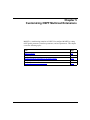
Chapter 4
Customizing DVMRP
DVMRP Concepts and Terminology ...............................................................................4-2
Neighbor Connections ..............................................................................................4-2
Source Route Advertisements .................................................................................4-4
How DVMRP Chooses a Route ...............................................................................4-5
Routing Table ...........................................................................................................4-6
Shortest-Path Trees .................................................................................................4-7
Customizing DVMRP Globally ........................................................................................4-8
Disabling and Reenabling DVMRP ...........................................................................4-9
Setting the Update Interval .....................................................................................4-10
vi
303527-A Rev. 00
Configuring Tree Pruning .......................................................................................4-11
Configuring DVMRP Timers ...................................................................................4-12
Setting the Route Expiration Timer ..................................................................4-12
Setting the Garbage Timer ..............................................................................4-13
Setting the Neighbor Report Timer ..................................................................4-14
Setting the Leaf Timer .....................................................................................4-15
Specifying a Probe Interval ....................................................................................4-16
Specifying a Route Switch Interval .........................................................................4-17
Estimating the Number of Routes ..........................................................................4-18
Logging Debugging Messages ...............................................................................4-19
Specifying the Maximum Number of Routes ..........................................................4-20
Enabling and Disabling Routing Policies ................................................................4-21
Customizing DVMRP on a Circuit .................................................................................4-22
Disabling and Reenabling DVMRP on a Circuit .....................................................4-22
Disabling Multicast Support on a Unicast Tunnel ...................................................4-23
Calculating a Route Metric and Comparing Route Costs ......................................4-24
Specifying a Threshold ...........................................................................................4-25
Configuring a Forwarding Table .............................................................................4-27
Disabling Advertisement of Local Networks ...........................................................4-29
Advertising a Default Route ...................................................................................4-30
Listening for a Default Route ..................................................................................4-31
Accepting a Report from a Nonstandard DVMRP Neighbor ..................................4-32
Configuring a Tunnel .....................................................................................................4-33
Supplying Addresses for the Tunnel .......................................................................4-34
Disabling and Reenabling the Tunnel .....................................................................4-35
Choosing the Encapsulation Mode ........................................................................4-36
Specifying the Cost ................................................................................................4-37
Specifying a TTL ....................................................................................................4-38
Configuring a Forwarding Table for the Tunnel .......................................................4-39
Advertising a Default Route ...................................................................................4-41
Listening for a Default Route ..................................................................................4-42
Specifying an Encapsulation Mode for Control Messages .....................................4-43
Accepting a Report from a Nonstandard DVMRP Neighbor ..................................4-44
Configuring DVMRP Announce Policies .......................................................................4-45
303527-A Rev. 00
vii
Chapter 5
Customizing OSPF Multicast Extensions
MOSPF Overview ...........................................................................................................5-2
Configuring MOSPF Globally .........................................................................................5-4
Enabling Deterministic Multicasting .........................................................................5-6
Specifying a Forwarding Timeout Value ...................................................................5-7
Specifying a Maximum Number of Queued Packets ................................................5-8
Enabling Dynamic TTL .............................................................................................5-9
Configuring Multicast Forwarding on an OSPF Interface .............................................5-10
Configuring Multicast-Capable External Routes ...........................................................5-11
Configuring MOSPF Announce Policies .......................................................................5-12
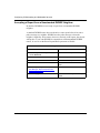
Chapter 6
Configuring QOSPF
Enabling the Deterministic Holddown Feature ................................................................6-3
Enabling Route Pinning ..................................................................................................6-4
Enabling the Opaque Capability .....................................................................................6-5
Enabling the Opaque Capability on an Interface ............................................................6-6
Chapter 7
Configuring RSVP
How RSVP Works ...........................................................................................................7-2
Configuring RSVP Globally ............................................................................................7-4
Disabling and Reenabling RSVP .............................................................................7-4
Choosing a Slot ........................................................................................................7-5
Configuring RSVP Message Logging ......................................................................7-6
Configuring RSVP on an Interface .................................................................................7-7
Disabling and Reenabling RSVP on an Interface .....................................................7-7
Setting the RSVP Default Refresh Timer .................................................................7-8
Setting the RSVP Default Lifetime Multiplier ............................................................7-9
Setting the RSVP Refresh Blockade Multiplier ......................................................7-10
Setting the TTL Override ........................................................................................7-11
Setting the Route Delay Value ...............................................................................7-12
Enabling and Disabling UDP Encapsulation ..........................................................7-13
viii
303527-A Rev. 00
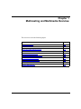
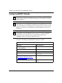
Chapter 8
Reserving Line Resources
About Line Resource Reservation ..................................................................................8-2
Resource Manager ...................................................................................................8-2
Supported Media ......................................................................................................8-3
How the Resource Manager Works with RSVP ..............................................................8-3
Setting the Estimated Bandwidth ....................................................................................8-4
Setting the Reservable Bandwidth .................................................................................8-5
Specifying the Traffic Queuing Algorithm ........................................................................8-6
Specifying the LRM Policing Algorithm ...........................................................................8-7
Setting the Bandwidth Interval ........................................................................................8-8
Setting the Inflate Reservations Percentage ..................................................................8-9
Specifying the Unreserved Policing Algorithm ..............................................................8-10
Specifying the Unreserved Queue Length ....................................................................8-11
Specifying the Multiline Select Algorithm ......................................................................8-12
Setting the Multiline Threshold Bandwidth ...................................................................8-13
Setting the Reservation Latency ...................................................................................8-14
Setting the Maximum Reservable Bandwidth for a Dataflow ........................................8-15
Setting the Maximum Buffer Space for a Dataflow .......................................................8-16
Chapter 9
Configuring IGMP Relay
Concepts and Terminology .............................................................................................9-2
Enabling and Disabling IGMP Relay Globally .................................................................9-7
Specifying a Timeout Value for Multicast Table Entries ..................................................9-9
Configuring Upstream Data Forwarding .......................................................................9-10
Specifying the Relay Interface Type .............................................................................9-11
Configuring Unsolicited Reports on an Upstream Interface .........................................9-13
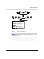
Configuring an AS Boundary Router for Use with IGMP Relay ....................................9-16
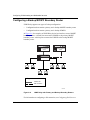
Configuring a Backup MOSPF Boundary Router .........................................................9-18
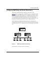
Configuring IGMP Relay with Router Redundancy ......................................................9-19
303527-A Rev. 00
ix
Appendix A
Site Manager Parameters
DVMRP Parameters ...................................................................................................... A-2
DVMRP Global Parameters ..................................................................................... A-2
DVMRP Circuit Parameters ..................................................................................... A-7
DVMRP Tunnel Parameters .................................................................................. A-11
IGMP Parameters ........................................................................................................ A-15
IGMP Global Configuration Parameters ................................................................ A-15
IGMP Static Host Parameters ............................................................................... A-19
IGMP Entry Interface Parameters ......................................................................... A-20
IP Configuration Parameters ....................................................................................... A-23
Resource Manager Parameters ................................................................................... A-25
OSPF Parameters for Multicast and QoS Extensions ................................................. A-31
OSPF Global Parameters ...................................................................................... A-31
OSPF Interface Parameters .................................................................................. A-34
RSVP Parameters ....................................................................................................... A-35
RSVP Global Parameters ...................................................................................... A-35
RSVP Interface Parameters .................................................................................. A-37
Announce Policy Parameters for Both DVMRP and MOSPF .......................... A-39
DVMRP-Specific Announce Policy Parameters .............................................. A-43
IGMP Group Policy Parameters ...................................................................... A-44
MTM Static Forwarding Policy Parameters ..................................................... A-48
IGMP Boundary Group Parameters ................................................................ A-51
Appendix B
Multicasting Tools
mtrace ............................................................................................................................ B-2
mrinfo ............................................................................................................................. B-4
rsvp ................................................................................................................................ B-5
Index
x
303527-A Rev. 00
Figures
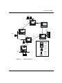
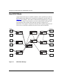
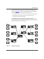
Figure 4-1.
Multicast Routers .....................................................................................4-3
Figure 5-1.
OSPF Autonomous Systems ...................................................................5-3
Figure 6-1.
QOSPF Topology .....................................................................................6-2
Figure 7-1.
RSVP Path Message ...............................................................................7-2
Figure 7-2.
RSVP Reserve Message .........................................................................7-3
Figure 9-1.
Multicast Network Topology with an IGMP Relay Device .........................9-3
Figure 9-2.
IGMP-R Host Queries and Responses ....................................................9-4
Figure 9-3.
IGMP-R and Upstream Multicast Data .....................................................9-5
Figure 9-4.
IGMP-R and Downstream Multicast Data ................................................9-6
Figure 9-5.
IGMP-R Routing Protocols .....................................................................9-17
Figure 9-6.
IGMP Relay with Primary and Backup Boundary Routers .....................9-18
Figure 9-7.
IGMP Relay with Router Redundancy ...................................................9-19
303527-A Rev. 00
xi
Tables
Table 4-1.
Parts of a Routing Table Entry .................................................................4-6
Table 4-2.
Recommended TTL and Threshold Values ...........................................4-25
Table 9-1.
IGMP Relay Forwarding Options ...........................................................9-10
Table 9-2.
IGMP Relay Interface Types ..................................................................9-12
Table 9-3.
Unsolicited IGMP Report Interval ..........................................................9-14
Table B-1.
Mtrace Options ....................................................................................... B-2
Table B-2.
Mrinfo Options ......................................................................................... B-4
Table B-3.
IP Subcommands .................................................................................... B-5
Table B-4.
Options for rsvp Subcommands ............................................................. B-6
303527-A Rev. 00
xiii
Preface
This guide describes configuring IGMP, DVMRP, MOSPF, QOSPF, RSVP, and
line services on a Bay Networks® router.
You can use the Bay Command Console (BCC™) or Site Manager to configure
IGMP on a router. In this guide, you will find instructions for using both the BCC
and Site Manager.
Before You Begin
Before using this guide, you must complete the following procedures. For a new
router:
•
Install the router (see the installation manual that came with your router).
•
Connect the router to the network and create a pilot configuration file (see
Quick-Starting Routers, Configuring BayStack Remote Access, or Connecting
ASN Routers to a Network).
Make sure that you are running the latest version of Bay Networks BayRS™ and
Site Manager software. For information about upgrading BayRS and Site
Manager, see the upgrading guide for your version of BayRS.
303527-A Rev. 00
xv
Configuring IP Multicasting and Multimedia Services
Text Conventions
This guide uses the following text conventions:
angle brackets (< >)
Indicate that you choose the text to enter based on the
description inside the brackets. Do not type the
brackets when entering the command.
Example: If the command syntax is:
ping <ip_address>, you enter:
ping 192.32.10.12
bold text
Indicates text that you need to enter and command
names and options.
Example: Enter show ip {alerts | routes}
Example: Use the dinfo command.
braces ({})
Indicate required elements in syntax descriptions
where there is more than one option. You must choose
only one of the options. Do not type the braces when
entering the command.
Example: If the command syntax is:
show ip {alerts | routes}, you must enter either:
show ip alerts or show ip routes.
brackets ([ ])
Indicate optional elements in syntax descriptions. Do
not type the brackets when entering the command.
Example: If the command syntax is:
show ip interfaces [-alerts], you can enter either:
show ip interfaces or show ip interfaces -alerts.
ellipsis points (. . . )
Indicate that you repeat the last element of the
command as needed.
Example: If the command syntax is:
ethernet/2/1 [<parameter> <value>] . . ., you enter
ethernet/2/1 and as many parameter-value pairs as
needed.
xvi
303527-A Rev. 00
Preface
italic text
Indicates file and directory names, new terms, book
titles, and variables in command syntax descriptions.
Where a variable is two or more words, the words are
connected by an underscore.
Example: If the command syntax is:
show at <valid_route>
valid_route is one variable and you substitute one value
for it.
screen text
Indicates system output, for example, prompts and
system messages.
Example: Set Bay Networks Trap Monitor Filters
separator ( > )
Shows menu paths.
Example: Protocols > IP identifies the IP option on the
Protocols menu.
vertical line ( | )
Separates choices for command keywords and
arguments. Enter only one of the choices. Do not type
the vertical line when entering the command.
Example: If the command syntax is:
show ip {alerts | routes}, you enter either:
show ip alerts or show ip routes, but not both.
Acronyms
303527-A Rev. 00
AUI
Attachment Unit Interface
BootP
Bootstrap Protocol
BRI
Basic Rate Interface
CCITT
International Telegraph and Telephone Consultative
Committee (now ITU-T)
CSMA/CD
carrier sense multiple access with collision detection
DLCMI
Data Link Control Management Interface
GUI
graphical user interface
HDLC
high-level data link control
xvii
Configuring IP Multicasting and Multimedia Services
xviii
IP
Internet Protocol
ISDN
Integrated Services Digital Network
ISO
International Organization for Standardization
ITU-T
International Telecommunications
Union-Telecommunications (formerly CCITT)
LAN
local area network
MAC
media access control
MAU
media access unit
MDI-X
media-dependent interface with crossover
NBMA
nonbroadcast multi-access
OSI
Open Systems Interconnection
OSPF
Open Shortest Path First (Protocol)
PPP
Point-to-Point Protocol
SMDS
switched multimegabit data service
SNMP
Simple Network Management Protocol
STP
shielded twisted-pair
TCP/IP
Transmission Control Protocol/Internet Protocol
Telnet
Telecommunication Network
TFTP
Trivial File Transfer Protocol
TPE
twisted-pair Ethernet
UTP
unshielded twisted-pair
WAN
wide area network
303527-A Rev. 00
Preface
Bay Networks Technical Publications
You can now print Bay Networks technical manuals and release notes free,
directly from the Internet. Go to support.baynetworks.com/library/tpubs/. Find the
Bay Networks product for which you need documentation. Then locate the
specific category and model or version for your hardware or software product.
Using Adobe Acrobat Reader, you can open the manuals and release notes, search
for the sections you need, and print them on most standard printers. You can
download Acrobat Reader free from the Adobe Systems Web site,
www.adobe.com.
You can purchase Bay Networks documentation sets, CDs, and selected technical
publications through the Bay Networks Collateral Catalog. The catalog is located
on the World Wide Web at support.baynetworks.com/catalog.html and is divided
into sections arranged alphabetically:
•
The “CD ROMs” section lists available CDs.
•
The “Guides/Books” section lists books on technical topics.
•
The “Technical Manuals” section lists available printed documentation sets.
Make a note of the part numbers and prices of the items that you want to order.
Use the “Marketing Collateral Catalog description” link to place an order and to
print the order form.
How to Get Help
For product assistance, support contracts, or information about educational
services, go to the following URL:
http://www.baynetworks.com/corporate/contacts/
Or telephone the Bay Networks Technical Solutions Center at:
800-2LANWAN
303527-A Rev. 00
xix
Chapter 1
Multicasting and Multimedia Overview
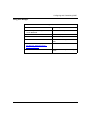
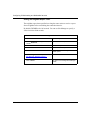
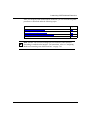
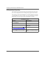
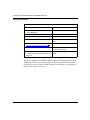
This overview covers the following topics:
303527-A Rev. 00
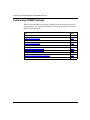
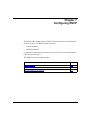
Topic
Page
Multicast Host Groups
1-2
Multicast Addresses
1-3
Internet Group Management Protocol
1-3
Distance Vector Multicast Routing Protocol
1-3
Multicast Extensions to OSPF
1-4
Quality of Service Extensions to OSPF
1-4
Resource Reservation Protocol
1-4
Bay Networks Resource Manager
1-4
IGMP Relay
1-5
Multicast Table Manager
1-5
1-1
Configuring IP Multicasting and Multimedia Services
Multicast Host Groups
IP multicasting is a method for addressing, routing, and delivering a datagram to a
collection of receivers -- called a host group.
Host groups can be permanent or transient:
•
A permanent host group has a well-known, administratively assigned IP
multicast group address. The address, not the membership, is permanent and
defines the group. A permanent host group can consist of zero or more
members.
•
A transient host group exists only as long as it has members that need its
services. IP addresses in the multicast range that are not reserved for
permanent groups are available for dynamic assignment to transient host
groups.
Any host system on any IP network can send a message to a multicast group using
the group’s IP multicast address. To receive a message addressed to a multicast
group, however, the host must be a member of the group and must reside on a
network where that group is registered with a local multicast router.
An IP multicasting host group can consist of zero or more members and places no
restrictions on its membership. Host members can reside anywhere; they can join
and leave the group at any time; and they can be members of more than one group
at the same time. In order to receive a multicast message from a host group, a host
must be a member of the group. However, anyone can send a multicast datagram:
a host does not need to be a member of a group to send a multicast message to its
members.
In general, hosts that are members of the same group reside on different networks.
However, a range of multicast addresses (224.0.0.x) is reserved for groups that are
locally scoped. All message traffic for these hosts remains on the local network.
Hosts that belong to a group in this address range and that reside in different
networks will not receive each other’s message traffic.
Note: Multicast data packets are affected by traffic filters. Therefore, you must
ensure that traffic filters configured on a multicast router do not prevent a host
that is a member of a group from receiving packets intended for that group.
1-2
303527-A Rev. 00
Multicasting and Multimedia Overview
Multicast Addresses
Each host group is assigned a unique multicast address. To reach all members of
the group, a sender uses the multicast address as the destination address of the
datagram.
An IP Version 4 multicast address is a Class D address (the high-order bits are set
to 1110) from 224.0.0.0 to 239.255.255.255.
The block of addresses from 224.0.0.1 to 224.0.0.255 is reserved for routing
protocols and other low-level protocols. Multicast routers will not forward
datagrams with addresses in this range.
Internet Group Management Protocol
The Internet Group Management Protocol (IGMP) has the following
characteristics:
•
Allows a host to register group memberships with the local queries router to
receive any datagrams sent to this router and targeted to a group with a
specific IP multicast address.
•
Allows a router to learn the existence of group members on its directly
attached networks. The router periodically sends a general group query
message to each of its local networks. Any host that is a member of a
multicasting group identifies itself by sending a response.
IGMP is described in Chapter 3.
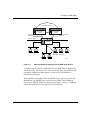
Distance Vector Multicast Routing Protocol
DVMRP is a distance vector type of multicast routing protocol. It advertises
shortest-path routes to multicasting source networks -- that is, any network
containing hosts that have the capability to issue multicast datagrams. (In this
respect, DVMRP is the opposite of RIP, which advertises routes to destination
networks.)
DVMRP is described in Chapter 4.
303527-A Rev. 00
1-3
Configuring IP Multicasting and Multimedia Services
Multicast Extensions to OSPF
Multicasting Extensions to OSPF (MOSPF) enhances the OSPF protocol by
providing capabilities that allow a router to forward multicast IP traffic within an
OSPF Version 2 autonomous system.
For instructions on configuring MOSPF, see Chapter 5.
Quality of Service Extensions to OSPF
QOSPF is an extension of OSPF and MOSPF that works in conjunction with the
Resource Reservation Protocol to provide quality of service (QoS) for multicast
data flows.
QOSPF is described in Chapter 6.
Resource Reservation Protocol
The Resource Reservation Protocol (RSVP) allows host systems in an IP network
to reserve resources on RSVP-capable routers for unicast or multicast dataflows.
(A dataflow is a transmission of packets from a source to one or more destinations
requiring a certain QoS.)
RSVP is described in Chapter 7.
Bay Networks Resource Manager
The Bay Networks Resource Manager lets you define a certain percentage of a
line’s bandwidth as reservable. Applications that require a guaranteed quality of
service can negotiate for the reservable bandwidth. When the router honors a
reservation request, the Resource Manager allocates bandwidth from the
reservable bandwidth, reducing the bandwidth available for other requests.
For information about the Bay Networks Resource Manager, see Chapter 8.
1-4
303527-A Rev. 00
Multicasting and Multimedia Overview
IGMP Relay
A router configured as an IGMP Relay (IGMP-R) device provides the following
services for an MOSPF AS boundary router:
•
Solicits multicast group membership information by sending IGMP host
membership queries to hosts on its attached local networks
•
Receives host membership reports and unsolicited join messages from hosts
on attached networks and forwards them to the MOSPF boundary router
•
Forwards multicast data to group members on locally attached networks
For information about IGMP Relay, see Chapter 9.
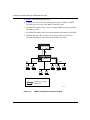
Multicast Table Manager
The Multicast Table Manager (MTM) makes it possible for different multicast
protocols to work together on the same router. MTM does the following:
303527-A Rev. 00
•
Manages DVMRP and MOSPF
•
Provides multicast routing support for RSVP
•
Supports MOSPF special features
•
Supports multicast tools for tracing routes
•
Maintains a multicast forwarding cache
•
Forwards multicast traffic
1-5
Chapter 2
Starting Multicasting and Multimedia Services
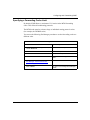
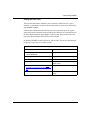
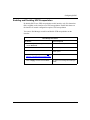
This chapter explains how to perform a basic configuration -- that is, a
configuration using all available defaults -- for the IP multicast services described
in this manual.
303527-A Rev. 00
Topic
Page
Starting IGMP
2-2
Starting DVMRP
2-3
Starting MOSPF
2-4
Starting RSVP
2-5
2-1
Configuring IP Multicasting and Multimedia Services
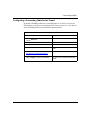
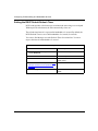
Starting IGMP
When you configure any multicasting protocol described in this manual, Site
Manager automatically configures IGMP on the slot and circuit.
IGMP is required for all types of multicasting. If you want the router to receive
and forward multicast packets (that is, packets with destination addresses from
224.0.0.255 to 239.255.255.255), IGMP must be running on the slot and circuit -even if the circuit is a point-to-point circuit that will not be involved in IGMP
group queries and join messages.
2-2
303527-A Rev. 00
Starting Multicasting and Multimedia Services
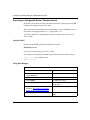
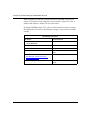
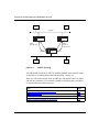
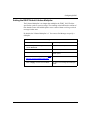
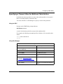
Starting DVMRP
To start DVMRP on the router:
1.
Configure a circuit on a slot and connector.
2.
Configure an IP interface on the circuit.
3.
Add DVMRP to the IP interface.
For information and instructions on using Site Manager to configure a circuit on a
slot and connector, see Configuring WAN Line Services or Configuring Ethernet,
FDDI, and Token Ring Services. When you have successfully configured the
circuit, the Select Protocols window opens. Proceed as follows:
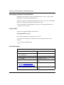
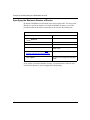
Site Manager Procedure
You do this
System responds
1. In the Select Protocols window, choose
the following protocols:
• IP
• DVMRP
Then click on OK.
The IP Configuration window opens.
2. Set the following parameters:
• IP Address
• Subnet Mask
• Transmit Bcast Addr
• UnNumbered Assoc Address
Click on Help or see the parameter
descriptions beginning on page A-23.
3. Click on OK.
Site Manager returns you to the
Configuration Manager window.
When you configure DVMRP on an IP interface, DVMRP is also configured
globally on the router.
DVMRP is now running on the router with default values for all global and
interface parameters. You customize DVMRP by modifying DVMRP parameters.
For information and instructions, see Chapter 4.
303527-A Rev. 00
2-3
Configuring IP Multicasting and Multimedia Services
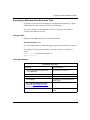
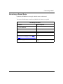
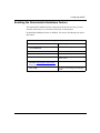
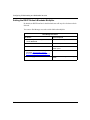
Starting MOSPF
MOSPF is a multicasting extension of OSPF. To enable MOSPF, you must add
OSPF to an IP interface and enable MOSPF multicast extensions to support one of
the following types of multicasting:
•
Intra-area multicasting
•
Intra-area and inter-area multicasting
•
Intra-area and inter-AS multicasting
•
All multicasting
For information about MOSPF multicasting types, see Chapter 5.
Site Manager Procedure
You do this
System responds
1. Configure OSPF on the router as
described in Configuring IP Services.
2. In the Configuration Manager window,
choose Protocols.
3.
Choose IP.
The Protocols menu opens.
The IP menu opens.
4. Choose OSPF.
The OSPF menu opens.
5. Choose Global.
The Edit OSPF Global Parameters
window opens.
6. Click on the Multicast Extensions
parameter. Site Manager: Multicast
Extensions parameter: page A-31
7. Choose the type of MOSPF you want to
configure, and then click on OK.
2-4
303527-A Rev. 00
Starting Multicasting and Multimedia Services
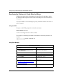
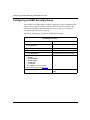
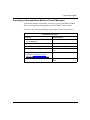
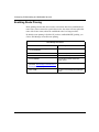
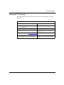
Starting RSVP
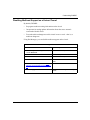
To start RSVP on the router:
1.
Configure a circuit on a slot and connector.
2.
Configure an IP interface on the circuit.
3.
Add RSVP to the IP interface.
For information and instructions on using Site Manager to configure a circuit on a
slot and connector, see see Configuring WAN Line Services or Configuring
Ethernet, FDDI, and Token Ring Services. When you have successfully
configured the circuit, the Select Protocols window opens. Proceed as follows:
Site Manager Procedure
You do this
System responds
1. In the Select Protocols window, choose
the following protocols:
• IP
• RSVP
Then click on OK.
The IP Configuration window opens.
2. Set the following parameters:
• IP Address
• Subnet Mask
• Transmit Bcast Addr
• UnNumbered Assoc Address
Click on Help or see the parameter
descriptions beginning on page A-23.
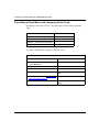
303527-A Rev. 00
3. Click on OK.
The Initial RSVP Global Parameters
widow appears.
4. Click on Save.
Site Manager queries you to create line
resources.
5. Click on OK.
The Edit Line Resources window opens.
6. Edit the following parameters:
• Estimated Bandwidth
• Reservable Bandwidth
Click on Help or see the parameter
descriptions beginning on page A-25.
Site Manager returns you to the
Configuration Manager window.
7. Click on OK.
Site Manager returns you to the
Configuration Manager window.
2-5
Configuring IP Multicasting and Multimedia Services
RSVP is now running on the router with default values for all parameters. You
customize RSVP by modifying RSVP parameters. For information and
instructions, see Chapter 7.
2-6
303527-A Rev. 00
Chapter 3
Configuring and Customizing IGMP
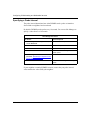
This chapter covers the following topics describing the Internet Group
Management Protocol (IGMP):
303527-A Rev. 00
Topic
Page
IGMP Concepts and Terminology
3-2
Customizing Global IGMP
3-4
Customizing IGMP on an Interface
3-13
Configuring a Static Host Entry
3-21
Configuring an IGMP Boundary Group
3-22
Configuring IGMP Policies
3-23
3-1
Configuring IP Multicasting and Multimedia Services
IGMP Concepts and Terminology
The Internet Group Management Protocol (IGMP) allows hosts to communicate
their desired group memberships to their local queries router to receive any
datagrams sent to this router and targeted to a group with a specific IP multicast
address. Bay Networks routers support IGMP Version 2.
A router communicates with the hosts on a local network by sending IGMP
queries. Hosts respond by issuing IGMP reports.
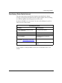
This section covers the following topics:
Topic
Page
IGMP Queries
3-2
IGMP Host Reports
3-3
Host Leave Messages
3-3
IGMP Queries
A router running IGMP periodically sends host membership queries to its attached
local networks. Routers that conform to RFC 1112 generate Version 1 queries.
Bay Networks routers configured with IGMP generate Version 2 queries.
If multiple IGMP routers exist on the network, Bay Networks routers designate
one router to send host member questions, using the following rules:
3-2
•
Choose a router that generates Version 1 queries over a router that generates
Version 2 queries.
•
Choose the router with the lowest IP address.
303527-A Rev. 00
Configuring and Customizing IGMP
IGMP Host Reports
A host that receives a membership query from a local router can respond with a
host membership report, one report for each joined multicast group. A host that
receives a query delays its reply by a random interval and listens for a reply from
any other host in the same host group. Consider a network that includes two host
members -- Host A and Host B -- of the same multicast group. The router sends
out a host membership query on the local network. Host A and Host B both
receive the query and listen on the network for a host membership report. Host B’s
delay time expires first, so it responds to the query with a membership report.
Hearing the response, Host A does not send a report of its own for the same group.
Each query from a router to a host includes a code field. IGMP inserts a
value -- n -- into this field specifying the maximum time in tenths of a second
within which the host must issue a reply. The host uses this value to calculate a
random value between 0 and n tenths of a second for the period that it waits before
sending a response.
If at least one host on the local network specifies that it is a member of a given
group, the router will forward to that network all datagrams bearing the group’s
multicast address.
Upon initialization, the host may immediately issue a report for each of its
supported multicast groups. The router accepts and processes these asynchronous
reports the same way it accepts requested reports.
Once in a steady state, hosts and routers communicate in a way that minimizes the
exchange of queries and reports.
Host Leave Messages
When a Version 2 host leaves a group, it issues a host leave message. The
multicast router on the network issues a group-specific query to determine
whether there are other group members on the network. If no host responds to the
query, the router assumes that no members belonging to that group exist on that
interface.
303527-A Rev. 00
3-3
Configuring IP Multicasting and Multimedia Services
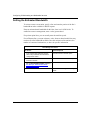
Customizing Global IGMP
When you configure a multicasting protocol on the router, IGMP is automatically
enabled with default values for all global parameters. You customize global IGMP
by modifying these parameters as described under the following topics:
3-4
Topic
Page
Enabling and Disabling IGMP
3-5
Estimating the Number of Groups
3-6
Specifying a Version Threshold Time
3-8
Configuring Logging
3-9
Enabling Join Acknowledgments
3-10
Specifying a Forwarding Cache Limit
3-11
Accepting a Nonlocal Report
3-12
303527-A Rev. 00
Configuring and Customizing IGMP
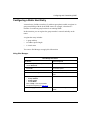
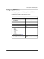
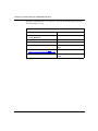
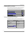
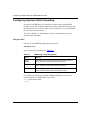
Enabling and Disabling IGMP
When you configure IGMP on the router, IGMP is automatically enabled.
You can use the BCC or Site Manager to disable and reenable IGMP on the router.
Using the BCC
Navigate to the global IGMP prompt and enter:
state state
state is one of the following:
enabled
disabled
Using Site Manager
Site Manager Procedure
You do this
System responds
1. In the Configuration Manager window,
choose Protocols.
The Protocols menu opens.
2. Choose IP.
The IP menu opens.
3. Choose IGMP.
The IGMP menu opens.
4. Choose Global.
The IGMP Global Configuration window
opens.
5. Set the Enable parameter. Site Manager:
Enable parameter: page A-15
6. Click on Save.
303527-A Rev. 00
You return to the Configuration Manager
window.
3-5
Configuring IP Multicasting and Multimedia Services
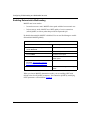
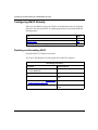
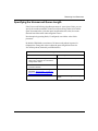
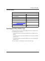
Estimating the Number of Groups
By default, IGMP estimates that 20 groups will be simultaneously active on this
router.
This estimate allows the router to utilize memory efficiently; exceeding this size
during router operation will not cause an error but may cause the router to
consume more memory than required.
Note: You do not need to include in the count any group from 224.0.0.0 to
224.0.0.255.
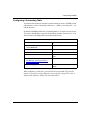
You can use the BCC or Site Manager to supply an estimate from 5 to 65,535
groups.
Using the BCC
Navigate to the global IGMP prompt and enter:
estimated-groups groups
groups is an integer from 5 to 65,535.
3-6
303527-A Rev. 00
Configuring and Customizing IGMP
Using Site Manager
Site Manager Procedure
You do this
System responds
1. In the Configuration Manager window,
choose Protocols.
The Protocols menu opens.
2. Choose IP.
The IP menu opens.
3. Choose IGMP.
The IGMP menu opens.
4. Choose Global.
The IGMP Global Configuration window
opens.
5. Set the Estimated Groups parameter.
Site Manager: Estimated Groups
parameter: page A-16
6. Click on Save.
303527-A Rev. 00
You return to the Configuration Manager
window.
3-7
Configuring IP Multicasting and Multimedia Services
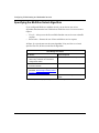
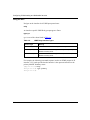
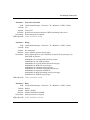
Specifying a Version Threshold Time
By default, 540 seconds can elapse after IGMP detects a Version 1 query before
IGMP tries to become the designated querier.
The value you specify should be greater than the Version 1 query rate of all IGMP
speakers on all networks directly connected to the router.
You can use the BCC or Site Manager to specify a version threshold time from
1 second to 65,535 seconds.
Using the BCC
Navigate to the global IGMP prompt and enter:
version-threshold threshold
threshold is the number of seconds from 1 to 65,535.
For example, the following command sets the version threshold time to 500
seconds:
igmp# version-threshold 500
igmp#
Using Site Manager
Site Manager Procedure
You do this
System responds
1. In the Configuration Manager window,
choose Protocols.
The Protocols menu opens.
2. Choose IP.
The IP menu opens.
3. Choose IGMP.
The IGMP menu opens.
4. Choose Global.
The IGMP Global Configuration window
opens.
5. Set the Version Threshold Time
parameter. Site Manager: Version
Threshold Time parameter: page A-16
6. Click on Save.
3-8
You return to the Configuration Manager
window.
303527-A Rev. 00
Configuring and Customizing IGMP
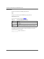
Configuring Logging
You can use the BCC or Site Manager to specify the messages you want IGMP to
log.
Using the BCC
Navigate to the global IGMP prompt and enter:
debug-log-flag flag
flag is an integer indicating the messages you want to log.
Using Site Manager
Site Manager Procedure
You do this
System responds
1. In the Configuration Manager window,
choose Protocols.
The Protocols menu opens.
2. Choose IP.
The IP menu opens.
3. Choose IGMP.
The IGMP menu opens.
4. Choose Global.
The IGMP Global Configuration window
opens.
5. Set the Debug parameter. Site Manager:
Debug parameter: page A-17
6. Click on Save.
303527-A Rev. 00
You return to the Configuration Manager
window.
3-9
Configuring IP Multicasting and Multimedia Services
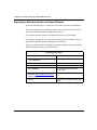
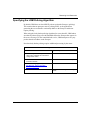
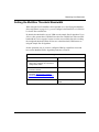
Enabling Join Acknowledgments
By default, IGMP does not respond with an acknowledgment to join requests from
host groups.
Using the following Site Manager procedure, you can configure IGMP globally to
respond to a join request by sending an IGMP query to the group.
Site Manager Procedure
You do this
System responds
1. In the Configuration Manager window,
choose Protocols.
The Protocols menu opens.
2. Choose IP.
The IP menu opens.
3. Choose IGMP.
The IGMP menu opens.
4. Choose Global.
The IGMP Global Configuration window
opens.
5. Set the Join Ack Enable parameter. Site
Manager: Join Ack Enable parameter:
page A-16
6. Click on Save.
You return to the Configuration Manager
window.
Note: This is a proprietary Bay Networks function. It is not part of the
standard IGMP protocol.
3-10
303527-A Rev. 00
Configuring and Customizing IGMP
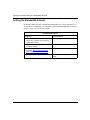
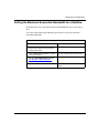
Specifying a Forwarding Cache Limit
By default, IGMP allows a maximum of 512 entries in the MTM forwarding
cache. This affects all multicasting protocols.
The MTM cache must be at least as large as individual routing protocol caches
(for example, the DVMRP cache).
You can use the following Site Manager procedure to set the forwarding cache to a
different value.
Site Manager Procedure
You do this
System responds
1. In the Configuration Manager window,
choose Protocols.
The Protocols menu opens.
2. Choose IP.
The IP menu opens.
3. Choose IGMP.
The IGMP menu opens.
4. Choose Global.
The IGMP Global Configuration window
opens.
5. Set the Forward Cache Limit parameter.
Site Manager: Forward Cache Limit
parameter: page A-17
6. Click on Save.
303527-A Rev. 00
You return to the Configuration Manager
window.
3-11
Configuring IP Multicasting and Multimedia Services
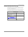
Accepting a Nonlocal Report
By default, IGMP rejects join and leave messages from nonlocal networks.
You can use the BCC or Site Manager to control the way IGMP handles nonlocal
reports.
Using the BCC
Navigate the the global IGMP prompt and enter:
ignore-nonlocal-report action
action is one of the following:
ignore (default)
accept
For example, the following command causes IGMP to accept join and leave
messages from nonlocal networks:
igmp# ignore-nonlocal-report accept
igmp#
Using Site Manager
.
Site Manager Procedure
You do this
System responds
1. In the Configuration Manager window,
choose Protocols.
The Protocols menu opens.
2. Choose IP.
The IP menu opens.
3. Choose IGMP.
The IGMP menu opens.
4. Choose Global.
The IGMP Global Configuration window
opens.
5. Set the NonLocal Reports parameter.
Site Manager: Forward Cache Limit
parameter: page A-17
6. Click on Save.
3-12
You return to the Configuration Manager
window.
303527-A Rev. 00
Configuring and Customizing IGMP
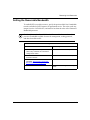
Customizing IGMP on an Interface
When you add a multicast protocol to an IP interface, IGMP is enabled with
default values for all interface parameters. You customize IGMP on the interface
by modifying these parameters as described under the following topics:
303527-A Rev. 00
Topic
Page
Enabling and Disabling IGMP on an Interface
3-14
Specifying a Query Rate
3-15
Specifying a Membership Timeout Interval
3-17
Specifying a Designated Router Timeout Interval
3-18
Specifying a Maximum Host Response Time
3-19
Specifying the Lifetime of a Cache Entry for Mtrace
3-20
3-13
Configuring IP Multicasting and Multimedia Services
Enabling and Disabling IGMP on an Interface
When you add a multicasting protocol to an IP interface, IGMP is automatically
enabled on the interface.
Note: IGMP is required for multicasting to function on the interface.
You can use the BCC or Site Manager to disable and reenable IGMP on the
interface
Using the BCC
Navigate to the IGMP prompt for the interface and enter:
state state
state is one of the following:
enabled
disabled
Using Site Manager
Site Manager Procedure
You do this
System responds
1. In the Configuration Manager window,
choose Protocols.
The Protocols menu opens.
2. Choose IP.
The IP menu opens.
3. Choose IGMP.
The IGMP menu opens.
4. Choose Entry.
The IGMP Entry Interface Parameters
window opens.
5. Set the Enable parameter. Site Manager:
Enable parameter: page A-20
6. Click on Apply, and then click on Done.
3-14
You return to the Configuration Manager
window.
303527-A Rev. 00
Configuring and Customizing IGMP
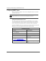
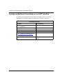
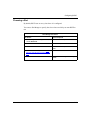
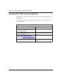
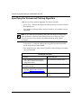
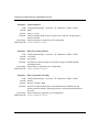
Specifying a Query Rate
By default, IGMP sends a group membership query on the interface every 120
seconds.
Specifying zero disables queries only. The router still forwards multicast
datagrams on this circuit.
Note: If another IGMP router on this network has taken on the query role, this
router will not send out queries unless it has not heard of any queries within
the number of seconds specified by the Designated Router Timeout parameter.
You can use the BCC or Site Manager to disable queries or specify a query rate
from 0 to 4096 seconds.
Using the BCC
Navigate the IGMP prompt for the interface and enter:
query-rate rate
rate is the number of seconds from 0 (disabling queries) to 4096.
For example, the following command specifies a query rate of 300 seconds:
igmp/2.2.2.2/3# query-rate 300
igmp/2.2.2.2/3#
303527-A Rev. 00
3-15
Configuring IP Multicasting and Multimedia Services
Using Site Manager
Site Manager Procedure
You do this
System responds
1. In the Configuration Manager window,
choose Protocols.
The Protocols menu opens.
2. Choose IP.
The IP menu opens.
3. Choose IGMP.
The IGMP menu opens.
4. Choose Entry.
The IGMP Entry Interface Parameters
window opens.
5. Set the Interface Query Rate parameter.
Site Manager: Interface Query Rate
parameter: page A-20
6. Click on Apply, and then click on Done.
3-16
You return to the Configuration Manager
window.
303527-A Rev. 00
Configuring and Customizing IGMP
Specifying a Membership Timeout Interval
By default, a local group membership is valid for 260 seconds without the receipt
of a subsequent report for that group.
You can use the BCC or Site Manager to specify an interval from 50 to 8192
seconds.
Using the BCC
Navigate to the IGMP prompt for the interface and enter:
membership-timeout seconds
seconds is a period from 50 to 8192 seconds.
For example, the following command specifies a membership timeout period of
300 seconds:
igmp/2.2.2.2/3# membership-timeout 300
igmp/2.2.2.2/3#
Using Site Manager
Site Manager Procedure
You do this
System responds
1. In the Configuration Manager window,
choose Protocols.
The Protocols menu opens.
2. Choose IP.
The IP menu opens.
3. Choose IGMP.
The IGMP menu opens.
4. Choose Entry.
The IGMP Entry Interface Parameters
window opens.
5. Set the Interface Membership Timeout
parameter. Site Manager: Interface
Membership Timeout parameter: page
A-20
6. Click on Apply, and then click on Done.
303527-A Rev. 00
You return to the Configuration Manager
window.
3-17
Configuring IP Multicasting and Multimedia Services
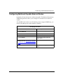
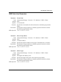
Specifying a Designated Router Timeout Interval
By default, 140 seconds can elapse after the last host query message before IGMP
considers the designated router to be down.
The value you specify should be greater than the query rate of all IGMP routers on
the network. The suggested value is (2 * Query Rate) + 20.
You can use the BCC or Site Manager to specify a timeout interval from 10 to
8192 seconds.
Using the BCC
Navigate to the IGMP prompt for the interface and enter:
dr-timeout seconds
seconds is an interval from 10 to 8192 seconds.
For example, the following command sets the timeout interval to 200 seconds:
igmp/2.2.2.2/3# dr-timeout 200
igmp/2.2.2.2/3#
Using Site Manager
Site Manager Procedure
You do this
System responds
1. In the Configuration Manager window,
choose Protocols.
The Protocols menu opens.
2. Choose IP.
The IP menu opens.
3. Choose IGMP.
The IGMP menu opens.
4. Choose Entry.
The IGMP Entry Interface Parameters
window opens.
5. Set the Designated Router Timeout
parameter. Site Manager: Designated
Router Timeout parameter: page A-21
6. Click on Apply, and then click on Done.
3-18
You return to the Configuration Manager
window.
303527-A Rev. 00
Configuring and Customizing IGMP
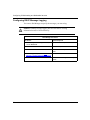
Specifying a Maximum Host Response Time
By default, a host must wait 100 tenths of a second before responding to a query.
IGMP places this value in the code field of an IGMP query.
You can use the BCC or Site Manager to specify a value from one tenth of a
second to 100 tenths of a second.
Using the BCC
Navigate to the IGMP prompt for the interface and enter:
max-host-response time
time is an integer from 1 to 100 specifying the response time in tenths of a second.
For example, the following command sets the host response to 25 tenths of a
second:
igmp/2.2.2.2/3# max-host-response 25
igmp/2.2.2.2/3#
Using Site Manager
Site Manager Procedure
You do this
System responds
1. In the Configuration Manager window,
choose Protocols.
The Protocols menu opens.
2. Choose IP.
The IP menu opens.
3. Choose IGMP.
The IGMP menu opens.
4. Choose Entry.
The IGMP Entry Interface Parameters
window opens.
5. Set the Max Host Response Time
parameter. Site Manager: Max Host
Response Time parameter: page A-21
6. Click on Apply, and then click on Done.
303527-A Rev. 00
You return to the Configuration Manager
window.
3-19
Configuring IP Multicasting and Multimedia Services
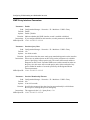
Specifying the Lifetime of a Cache Entry for Mtrace
IGMP creates entries in the forwarding cache specifically for the Mtrace utility.
By default, IGMP keeps these entries in the forwarding cache for a maximum of
30 seconds.
You can use the BCC or Site Manager to specify a different lifetime value from 30
to 8192 seconds.
Using the BCC
Navigate to the IGMP prompt for the interface and enter:
mtrace-lifetime seconds
seconds is an integer from 30 to 8192 seconds.
For example, the following command sets the Mtrace cache entry lifetime to 60
seconds:
igmp/2.2.2.2/3# mtrace-lifetime 60
igmp/2.2.2.2/3#
Using Site Manager
Site Manager Procedure
You do this
System responds
1. In the Configuration Manager window,
choose Protocols.
The Protocols menu opens.
2. Choose IP.
The IP menu opens.
3. Choose Multicast.
The Multicast menu opens.
4. Choose IGMP.
The IGMP menu opens.
5. Choose Entry.
The IGMP Entry Interface Parameters
window opens.
6. Set the Mtrace Entry Lifetime parameter.
Site Manager: Mtrace Entry Lifetime
parameter: page A-21
7. Click on Apply, and then click on Done.
3-20
You return to the Configuration Manager
window.
303527-A Rev. 00
Configuring and Customizing IGMP
Configuring a Static Host Entry
A network may include a member of a multicast group that is unable to register its
group membership with the local IGMP router, for example, a host that is a
member of a multicast group but that is not running IGMP.
In this situation, you can register the group member’s network statically on the
router.
A registration entry includes:
•
A group address
•
An address prefix length
•
A circuit name
You can use Site Manager to supply this information.
Using Site Manager
Site Manager Procedure
You do this
System responds
1. In the Configuration Manager window,
choose Protocols.
The Protocols menu opens.
2. Choose IP.
The IP menu opens.
3. Choose IGMP.
The IGMP menu opens.
4. Choose Static Groups.
The IP IGMP Static Groups window
opens.
5. Set the following parameters:
• Group Address
• Prefix Length
• Circuit Name
Click on Help or see the parameter
descriptions beginning on page A-19.
6. Click on Apply, and then click on Done.
303527-A Rev. 00
You return to the Configuration Manager
window.
3-21
Configuring IP Multicasting and Multimedia Services
Configuring an IGMP Boundary Group
You configure an IGMP boundary group by supplying a range of multicast group
addresses (expressed as an address and a prefix) and a list of IP interfaces. No
multicast group address that falls within the range you specify is accepted or
forwarded on the interfaces you specify.
You can use Site Manager to define an IGMP boundary group.
Site Manager Procedure
You do this
System responds
1. In the Configuration Manager window,
choose Protocols.
The Protocols menu opens.
2. Choose IP.
The IP menu opens.
3. Choose IGMP.
The IGMP menu opens.
4. Choose Boundaries.
The IP Boundary Group window opens.
5. Set the following parameters:
• Enable
• Group Address
• Prefix Length
• Circuit List
• Tunnel List
Click on Help or see the parameter
descriptions beginning on page A-51.
6. Click on Apply, and then click on Done.
3-22
You return to the Configuration Manager
window.
303527-A Rev. 00
Configuring and Customizing IGMP
Configuring IGMP Policies
Site Manager allows you to create IGMP group pollicies and IGMP Static
Forwarding Entry policies.
Use the following procedure to create IGMP group policies:
Site Manager Procedure
You do this
System responds
1. In the Configuration Manager window,
choose Protocols.
The Protocols menu opens.
2. Choose IP.
The IP menu opens.
3. Choose Policies.
The IP Policies menu opens.
4. Choose IGMP.
The IGMP Policies menu opens.
5. Chose IGMP Group Policy Filters.
The IGMP Group Policy Filters window
opens.
6. Set the the following parameters:
• Name
• Sources
• Action
• Precedence
• Group
• Circuits
• Senders
Click on Help or see the parameter
descriptions starting on page A-44.
7. Click on Apply, and then click on Done.
303527-A Rev. 00
You return to the Configuration Manager
window.
3-23
Configuring IP Multicasting and Multimedia Services
Use the following procedure to configure IGMP Static Forwarding Entry policies:
Site Manager Procedure
You do this
System responds
1. In the Configuration Manager window,
choose Protocols.
The Protocols menu opens.
2. Choose IP.
The IP menu opens.
3. Choose Policies.
The IP Policies menu opens.
4. Choose IGMP.
The IGMP Policies menu opens.
5. Chose IGMP Static Forwarding Entry.
The IGMP Static Forwarding Entry
window opens.
6. Set the the following parameters:
• Name
• Groups
• Preference
• Precedence
• Sources
• In Circuits
• Out Circuits
Click on Help or see the parameter
descriptions starting on page A-48.
7. Click on Apply, and then click on Done.
3-24
You return to the Configuration Manager
window.
303527-A Rev. 00
Chapter 4
Customizing DVMRP
This chapter describes the Distance Vector Multicast Routing Protocol (DVMRP).
303527-A Rev. 00
Topic
Page
DVMRP Concepts and Terminology
4-2
Customizing DVMRP Globally
4-8
Customizing DVMRP on a Circuit
4-22
Configuring a Tunnel
4-33
Configuring DVMRP Announce Policies
4-45
4-1
Configuring IP Multicasting and Multimedia Services
DVMRP Concepts and Terminology
DVMRP is a multicasting protocol that provides a mechanism for routers to
propagate multicast datagrams in a manner that minimizes the number of excess
copies sent to any particular network.
This section covers the following topics:
Topic
Page
Neighbor Connections
4-2
Source Route Advertisements
4-4
How DVMRP Chooses a Route
4-5
Routing Table
4-6
Shortest-Path Trees
4-7
Neighbor Connections
In a DVMRP environment, neighbors are multicasting routers that are connected
directly or through a tunnel:
•
Directly connected neighbors are routers that have an interface to the same
network.
•
Tunnel-connected neighbors are multicast routers that communicate through a
unicast network, exchanging DVRMP messages that are encapsulated in IP
datagrams.
In Figure 4-1, for example, multicasting router A has two neighbors, router B and
router C. Router A and router B are connected directly -- they both have interfaces
to net 6. router A and router C communicate through a tunnel that includes a
unicast router.
4-2
303527-A Rev. 00
Customizing DVMRP
Net 1
a3
a1
a2
A
Net 6
b1
b3
Net 3
B
c1
Net 2
c3
b2
c2
d1
Net 4
C
Net 8
D
d2
Key
d3
Multicast
router
Net 9
e1
Unicast
router
E
Net 5
e2
Multicast
host
Multicast
circuit
Tunnel
IP00031A
Figure 4-1.
303527-A Rev. 00
Multicast Routers
4-3
Configuring IP Multicasting and Multimedia Services
At startup, a DVMRP multicasting router:
1. Initializes its routing table with information on all of its local networks
2. Learns the existence of its neighbors by sending a probe for all routes on each
of its multicast interfaces (both physical circuits and tunnels)
3. Receives reports from its neighbors containing the routing information
(including route costs)
In Figure 4-1, for example, router D becomes active and issues routing probes on
four multicasting interfaces. router D receives reports from its multicasting
neighbors, routers B, C, and E.
Source Route Advertisements
A source network is any network containing hosts that have the capability to issue
multicast datagrams. DVMRP advertises shortest-path routes to multicasting
source networks. In this respect, DVMRP is the opposite of RIP, which advertises
routes to destination networks.
Periodically, each multicasting router issues full or partial routing information on
each DVMRP circuit, using DVMRP report messages. This routing information
represents the sending router’s cost to reach the specified source network. (The
cost is the sum of the hop metrics along the shortest path to the given source
network.)
Upon receiving a DVMRP report from another router, DVMRP reexamines its
routing table to determine if the shortest path information needs updating.
Specifically, DVMRP looks in the routing table for an entry describing a route to
the same source network. If one exists, DVMRP compares the cost of the two
routes and stores the route with the lower cost in its routing table.
A router will not send route reports on an interface until it knows (by means of
received probes or reports) that it has a neighboring multicast router on that
interface. It will continue to send probes periodically on an interface.
4-4
303527-A Rev. 00
Customizing DVMRP
How DVMRP Chooses a Route
Each DVMRP interface is configured with a metric that indicates the cost of the
hop. A router that receives multiple route reports for the same multicasting source
network:
•
Compares the cost specified in each (based on the metric field)
•
Stores information from the report with the lowest cost in its routing table
A route metric is the sum of all the interface (hop) metrics from a given route
source to a given router.
In Figure 4-1 on page 4-3, for example, router D receives two reports for the
network connected to multicasting router A, one from router B and one from
router C. Using the metrics contained in the route reports, router D determines that
the cost of the tunneled route is greater than the cost of the route that uses direct
physical connections. Router D discards the route received from router C and
stores the route received from router B.
Router D then declares router B to be the next-hop neighbor and interface d1 to be
the next-hop interface. After a next-hop neighbor has been declared for a route,
the route updates received from that neighbor for that route take precedence until
either the route times out or until another router advertises a better metric for that
route.
303527-A Rev. 00
4-5
Configuring IP Multicasting and Multimedia Services
Routing Table
Table 4-1 shows the principal items in a routing table entry.
Table 4-1.
Item
Parts of a Routing Table Entry
Description
Source subnet address and Address and mask of a subnetwork containing a host
mask
sourcing multicast datagrams
From-gateway
Previous-hop router leading back to the source subnet
TTL
Number of seconds before this entry is removed from the
routing table
Note that the source subnet and the previous-hop router in the DVMRP routing
table are the opposite of the destination subnet and next-hop router in a RIP
routing table.
Using this information, the router can:
1. Receive a multicast datagram and determine if the datagram has arrived on the
interface that is on the shortest path to the source network.
2. Drop the datagram if it has not arrived on the shortest-path interface.
3. Flood the multicast datagram to all active downstream DVMRP neighbors.
4-6
303527-A Rev. 00
Customizing DVMRP
Shortest-Path Trees
Route information used by DVMRP is independent of any other routing
information used by the router -- for example, routes provided by RIP. The
purpose of this routing information is to create a shortest-path tree entry in the
routing table for the propagation of multicast datagrams.
The shortest-path tree entry indicates the interface that provides the shortest path
to the network that is the source of the multicast datagram.
In Figure 4-1 on page 4-3, for example, the routing table on router D includes an
entry describing the shortest-path route to the network connected to router A. The
entry indicates that Interface d1 provides the shortest path to that source network.
A shortest-path tree also indicates those interfaces that are on the shortest path to
that source network from a neighboring router.
Router E considers the network connecting it to router D to be on the shortest path
to the source network connected to router A. Router D has an interface (d3) that is
part of the shortest path from router E from the network connected to router A.
If neighboring routers have the same metric to a given source network, the router
with the lower IP address is responsible for propagating multicast traffic
originating from that source network onto the network or tunnel that is common to
these neighboring routers.
A network is considered a leaf network if it has no dependent downstream
neighbors for a source. In Figure 4-1, the network connected to router E (net 5) is
a leaf network.
303527-A Rev. 00
4-7
Configuring IP Multicasting and Multimedia Services
Customizing DVMRP Globally
When you start DVMRP on the router, DVMRP runs with default values for all
global protocols. You customize DVMRP by modifying parameters as described
under the following topics:
4-8
Topic
Page
Disabling and Reenabling DVMRP
4-9
Setting the Update Interval
4-10
Configuring Tree Pruning
4-11
Configuring DVMRP Timers
4-12
Specifying a Probe Interval
4-16
Specifying a Route Switch Interval
4-17
Estimating the Number of Routes
4-18
Logging Debugging Messages
4-19
Specifying the Maximum Number of Routes
4-20
Enabling and Disabling Routing Policies
4-21
303527-A Rev. 00
Customizing DVMRP
Disabling and Reenabling DVMRP
You can use Site Manager to disable and reenable DVMRP on the router.
Site Manager Procedure
You do this
System responds
1. In the Configuration Manager window,
choose Protocols.
The Protocols menu opens.
2. Choose IP.
The IP menu opens.
3. Choose DVMRP.
The DVMRP menu opens.
4. Choose Global.
The DVMRP Global Configuration
window opens.
5. Set the Enable parameter. Site Manager:
Enable parameter: page A-2
6. Click on Save.
303527-A Rev. 00
You return to the Configuration Manager
window.
4-9
Configuring IP Multicasting and Multimedia Services
Setting the Update Interval
Periodically, each multicasting router issues full or partial routing information on
each DVMRP circuit, using DVMRP report messages. This routing information
represents the sending router’s cost to reach the specified network. (The cost is the
sum of the hop metrics along the shortest path to the given source network.)
You can use Site Manager to:
•
Specify how often routing messages containing complete routing tables are
sent.
•
Specify the minimum amount of time between triggered updates. Triggered
updates are sent when routing information changes. Issuing a full update
restarts the triggered update timer. Therefore, the triggered update interval
you specify must be shorter than the full update interval you set.
Site Manager Procedure
You do this
System responds
1. In the Configuration Manager window,
choose Protocols.
The Protocols menu opens.
2. Choose IP.
The IP menu opens.
3. Choose DVMRP.
The DVMRP menu opens.
4. Choose Global.
The DVMRP Global Configuration
window opens.
5. Set the following parameters:
• Full Update Interval
• Triggered Update Interval
Click on Help or see the parameter
descriptions beginning on page A-2.
6. Click on Save.
4-10
You return to the Configuration Manager
window.
303527-A Rev. 00
Customizing DVMRP
Configuring Tree Pruning
If no members are detected on a branch of the shortest path tree for a given group,
DVMRP prunes the branch.
The following conditions cause DVMRP to prune the shortest-path tree for a given
group:
•
The router determines that the attached network on which the host is located
(or any other locally attached network) has no active member of the group.
•
The router determines that all neighbors on all attached networks other than
the next-hop network to the source have pruned off the source and group.
•
The router determines that it is not located on the shortest network path to any
remote network that includes a member of the group.
•
The router sends a DVMRP prune message to its DVMRP neighbor. The
neighbor removes the router from its forwarding table.
If the host later rejoins the group, the router sends the neighbor a DVMRP
graft message. The neighbor restores the router to its forwarding table.
Tree pruning is enabled on the router by default. You can use Site Manager to
disable and reenable tree pruning on the router.
Site Manager Procedure
You do this
System responds
1. In the Configuration Manager window,
choose Protocols.
The Protocols menu opens.
2. Choose IP.
The IP menu opens.
3. Choose DVMRP.
The DVMRP menu opens.
4. Choose Global.
The DVMRP Global Configuration
window opens.
5. Set the Pruning Enable parameter. Site
Manager: Pruning Enable parameter:
page A-6
6. Click on Save.
303527-A Rev. 00
You return to the Configuration Manager
window.
4-11
Configuring IP Multicasting and Multimedia Services
Configuring DVMRP Timers
When a router adds or updates a route, it uses configurable timers to control the
useful life of the route.
Note: DVMRP timers must be the same throughout the network.
Setting the Route Expiration Timer
The route expiration timer determines how long DVMRP waits for an update
message indicating that a route is reachable. Upon expiration of this timer, this
route is advertised as unreachable until it is refreshed or until it is garbaged.
By default, DVMRP sets the route expiration time at 200 seconds.You can use Site
Manager to set the route expiration time from 20 to 4000 seconds.
Site Manager Procedure
You do this
System responds
1. In the Configuration Manager window,
choose Protocols.
The Protocols menu opens.
2. Choose IP.
The IP menu opens.
3. Choose DVMRP.
The DVMRP menu opens.
4. Choose Global.
The DVMRP Global Configuration
window opens.
5. Set the Route Expiration Timeout
parameter. Site Manager: Route
Expiration Timeout parameter: page A-3
6. Click on Save.
4-12
You return to the Configuration Manager
window.
303527-A Rev. 00
Customizing DVMRP
Setting the Garbage Timer
The garbage timer determines how long DVMRP advertises a route as
unreachable before it removes the route from the routing table. The difference
between this value and the route expiration timeout value represents the time
period that the route will be advertised as unreachable without subsequent
refreshment.
By default, DVMRP sets the garbage timer to 340 seconds. You can use Site
Manager to set the value from 40 to 8000 seconds.
Site Manager Procedure
You do this
System responds
1. In the Configuration Manager window,
choose Protocols.
The Protocols menu opens.
2. Choose IP.
The IP menu opens.
3. Choose DVMRP.
The DVMRP menu opens.
4. Choose Global.
The DVMRP Global Configuration
window opens.
5. Set the Garbage Timeout parameter. Site
Manager: Garbage Timeout parameter:
page A-4
6. Click on Save.
You return to the Configuration Manager
window.
Enter a value that is greater than the value you specified for the route expiration
timer to allow enough time for the route to be advertised as unreachable.
303527-A Rev. 00
4-13
Configuring IP Multicasting and Multimedia Services
Setting the Neighbor Report Timer
The neighbor report timer specifies how long the router waits to receive a report
from a neighbor before considering the connection inactive.
By default, DVMRP waits 140 seconds. You can use Site Manager to specify a
value from 40 to 8000 seconds.
Site Manager Procedure
You do this
System responds
1. In the Configuration Manager window,
choose Protocols.
The Protocols menu opens.
2. Choose IP.
The IP menu opens.
3. Choose DVMRP.
The DVMRP menu opens.
4. Choose Global.
The DVMRP Global Configuration
window opens.
5. Set the Neighbor Timeout parameter.
Site Manager: Neighbor Timeout
parameter: page A-3
6. Click on Save.
4-14
You return to the Configuration Manager
window.
303527-A Rev. 00
Customizing DVMRP
Setting the Leaf Timer
The leaf timer determines whether or not a network or tunnel local to a given
interface is considered to be part of the shortest path to a given source network by
any DVMRP neighbor.
If during this time the local interface has not received a route report for a given
source network, this network or tunnel and its local interface are considered not to
lie in the shortest path for any neighbor. In other words, the local network is not
part of the shortest path to that specific source network.
By default, DVMRP sets the leaf timer at 200 seconds. You can use Site Manager
to specify a value from 25 to 4000 seconds.
Site Manager Procedure
You do this
System responds
1. In the Configuration Manager window,
choose Protocols.
The Protocols menu opens.
2. Choose IP.
The IP menu opens.
3. Choose DVMRP.
The DVMRP menu opens.
4. Choose Global.
The DVMRP Global Configuration
window opens.
5. Set the Leaf Timeout parameter. Site
Manager: Leaf Timeout parameter: page
A-3
6. Click on Save.
303527-A Rev. 00
You return to the Configuration Manager
window.
4-15
Configuring IP Multicasting and Multimedia Services
Specifying a Probe Interval
The probe interval determines how often DVMRP sends a probe on interfaces
from which no neighbors have been heard.
By default, DVMRP sends a probe every 10 seconds. You can use Site Manager to
specify a value from 5 to 30 seconds.
Site Manager Procedure
You do this
System responds
1. In the Configuration Manager window,
choose Protocols.
The Protocols menu opens.
2. Choose IP.
The IP menu opens.
3. Choose DVMRP.
The DVMRP menu opens.
4. Choose Global.
The DVMRP Global Configuration
window opens.
5. Set the Neighbor Probe Interval
parameter. Site Manager: Neighbor Probe
Interval parameter: page A-5
6. Click on Save.
You return to the Configuration Manager
window.
If your neighbor is running DVMRP mrouted, ensure that your probe interval
value matches the value used by the neighbor.
4-16
303527-A Rev. 00
Customizing DVMRP
Specifying a Route Switch Interval
The route switch interval specifies how long the router should wait, without
receiving a subsequent route update from the original neighbor, before switching
to a different neighbor advertising equal cost for this route.
By default, DVMRP waits 140 seconds. You can use Site Manager to specify a
value from 20 to 2000 seconds.
Site Manager Procedure
You do this
System responds
1. In the Configuration Manager window,
choose Protocols.
The Protocols menu opens.
2. Choose IP.
The IP menu opens.
3. Choose DVMRP.
The DVMRP menu opens.
4. Choose Global.
The DVMRP Global Configuration
window opens.
5. Set the Route Switch Timeout
parameter. Site Manager: Route Switch
Timeout parameter: page A-5
6. Click on Save.
You return to the Configuration Manager
window.
If your neighbor is running DVMRP mrouted, the recommended value is 140
seconds.
303527-A Rev. 00
4-17
Configuring IP Multicasting and Multimedia Services
Estimating the Number of Routes
By default, DVMRP preallocates a routing table for 25 entries. You can use Site
Manager to specify the number of entries (10 or more).
Site Manager Procedure
You do this
System responds
1. In the Configuration Manager window,
choose Protocols.
The Protocols menu opens.
2. Choose IP.
The IP menu opens.
3. Choose DVMRP.
The DVMRP menu opens.
4. Choose Global.
The DVMRP Global Configuration
window opens.
5. Set the Estimated Routes parameter.
Site Manager: Estimated Routes
parameter: page A-4
6. Click on Save.
You return to the Configuration Manager
window.
Enter a value that the router can use for preallocating routing tables. For an
MBone implementation, a value of 3000 or higher is recommended.
Note that routes are kept on a per-source-network basis, independent of multicast
groups. This number must include a route for every network that is local to a
circuit configured for multicasting. This allows the router to utilize memory
efficiently. Exceeding this size during router operation will not cause an error but
may cause the router to consume more memory than required.
4-18
303527-A Rev. 00
Customizing DVMRP
Logging Debugging Messages
By default, DVMRP does not log debugging messages. You can use Site Manager
to enable the logging of debugging messages and to specify the level of debug
messages.
Site Manager Procedure
You do this
System responds
1. In the Configuration Manager window,
choose Protocols.
The Protocols menu opens.
2. Choose IP.
The IP menu opens.
3. Choose DVMRP.
The DVMRP menu opens.
4. Choose Global.
The DVMRP Global Configuration
window opens.
5. Set the Debug Level parameter. Site
Manager: Debug Level parameter: page
A-5
6. Click on Save.
303527-A Rev. 00
You return to the Configuration Manager
window.
4-19
Configuring IP Multicasting and Multimedia Services
Specifying the Maximum Number of Routes
By default, DVMRP stores all learned routes in the routing table. You can use Site
Manager to specify the number of routes that DVMRP can learn per slot. This
parameter limits the number of routes that can be stored in the routing table.
Site Manager Procedure
You do this
System responds
1. In the Configuration Manager window,
choose Protocols.
The Protocols menu opens.
2. Choose IP.
The IP menu opens.
3. Choose DVMRP.
The DVMRP menu opens.
4. Choose Global.
The DVMRP Global Configuration
window opens.
5. Set the Max Routes parameter. Site
Manager: Max Routes parameter: page
A-6
6. Click on Save.
You return to the Configuration Manager
window.
If you specify a maximum number of routes, you must include a route for every
local network that has a circuit configured for multicasting.
4-20
303527-A Rev. 00
Customizing DVMRP
Enabling and Disabling Routing Policies
By default, routing policies are globally disabled.
This parameter allows you to configure a policy for the specified route. Bay
Networks currently supports only the policies that do not advertise the specified
route or route range. Bay Networks supports policies that advertise a default route
for the specified route or route range.
You can use the following Site Manager procedure to enable and disable routing
policies as required.
Site Manager Procedure
You do this
System responds
1. In the Configuration Manager window,
choose Protocols.
The Protocols menu opens.
2. Choose IP.
The IP menu opens.
3. Choose DVMRP.
The DVMRP menu opens.
4. Choose Global.
The DVMRP Global Configuration
window opens.
5. Set the Policy Enable parameter. Site
Manager: Policy Enable parameter: page
A-6
6. Click on Save.
303527-A Rev. 00
You return to the Configuration Manager
window.
4-21
Configuring IP Multicasting and Multimedia Services
Customizing DVMRP on a Circuit
You customize DVMRP on a circuit by modifying DVMRP parameters as
described under the following topics:
Topic
Page
Disabling and Reenabling DVMRP on a Circuit
4-22
Disabling Multicast Support on a Unicast Tunnel
4-23
Calculating a Route Metric and Comparing Route Costs
4-24
Specifying a Threshold
4-25
Configuring a Forwarding Table
4-27
Disabling Advertisement of Local Networks
4-29
Advertising a Default Route
4-30
Listening for a Default Route
4-31
Accepting a Report from a Nonstandard DVMRP Neighbor
4-32
Disabling and Reenabling DVMRP on a Circuit
By default, DVMRP is enabled on a circuit. You can use Site Manager to disable
and reenable it.
Site Manager Procedure
You do this
System responds
1. In the Configuration Manager window,
choose Protocols.
The Protocols menu opens.
2. Choose IP.
The IP menu opens.
3. Choose DVMRP.
The DVMRP menu opens.
4. Choose Circuit.
The DVMRP Circuit Parameters window
opens.
5. Set the Enable parameter. Site Manager:
Enable parameter: page A-7
6. Click on Apply, and then click on Done.
4-22
You return to the Configuration Manager
window.
303527-A Rev. 00
Customizing DVMRP
Disabling Multicast Support on a Unicast Tunnel
By default, DVMRP:
•
Propagates multicast routing information on the circuit
•
Incorporates in routing updates information about the source network
associated with this circuit
•
Forwards multicast datagrams on this circuit in native mode -- that is, as
multicast datagrams
Using Site Manager, you can disable multicast support on the circuit.
Site Manager Procedure
You do this
System responds
1. In the Configuration Manager window,
choose Protocols.
The Protocols menu opens.
2. Choose IP.
The IP menu opens.
3. Choose DVMRP.
The DVMRP menu opens.
4. Choose Circuit.
The DVMRP Circuit Parameters window
opens.
5. Set the Route Enable parameter. Site
Manager: Route Enable parameter: page
A-7
6. Click on Apply, and then click on Done.
303527-A Rev. 00
You return to the Configuration Manager
window.
4-23
Configuring IP Multicasting and Multimedia Services
Calculating a Route Metric and Comparing Route Costs
By default, a circuit has a cost of 1. Bay Networks recommends the following
values:
Hop
Metric
LAN, or tunnel across a single LAN
1
Multihop tunnel
2 or 3
Serial link, or tunnel across a serial link
1
Backup tunnel
Primary tunnel metric + 1
You can use Site Manager to assign a cost from 1 to 31.
Site Manager Procedure
You do this
System responds
1. In the Configuration Manager window,
choose Protocols.
The Protocols menu opens.
2. Choose IP.
The IP menu opens.
3. Choose DVMRP.
The DVMRP menu opens.
4. Choose Circuit.
The DVMRP Circuit Parameters window
opens.
5. Set the Metric parameter. Site Manager:
Metric parameter: page A-8
6. Click on Apply, and then click on Done.
4-24
You return to the Configuration Manager
window.
303527-A Rev. 00
Customizing DVMRP
Specifying a Threshold
Threshold values control the scope of datagram delivery. The threshold is the
minimum IP TTL required for a multicast datagram to be forwarded out a given
interface.
For mrouted compatibility, multicast datagrams originated by the router have a
TTL of 1. These datagrams are not compared against the TTL. Unicast datagrams
originated by the router (for example, for route reports issued via a tunnel) have a
TTL of 255. A datagram that is to be forwarded through a tunnel is first compared
against the threshold and, if accepted, is then encapsulated in an IP datagram with
a TTL of 64.
Table 4-2 lists:
•
Originating TTL values recommended for certain types of multicast
applications
•
Threshold values recommended for routers to permit the forwarding of
packets from these applications
These values are recommended for topologies that will connect to the MBone.
Table 4-2.
Recommended TTL and Threshold Values
Multicast Application
303527-A Rev. 00
TTL
Threshold
IETF channel 1 low-rate GSM audio
255
224
IETF channel 2 low-rate GSM audio
223
192
IETF channel 1 PCM audio
191
160
IETF channel 2 PCM audio
159
128
IETF channel 1 video
127
96
IETF channel 2 video
95
64
Local event audio
63
32
Local event video
31
1
4-25
Configuring IP Multicasting and Multimedia Services
By default, DVMRP uses a TTL value of 1. You can use Site Manager to specify a
TTL value from 1 to 254.
Site Manager Procedure
You do this
System responds
1. In the Configuration Manager window,
choose Protocols.
The Protocols menu opens.
2. Choose IP.
The IP menu opens.
3. Choose DVMRP.
The DVMRP menu opens.
4. Choose Circuit.
The DVMRP Circuit Parameters window
opens.
5. Set the Threshold parameter. Site
Manager: Threshold parameter: page A-8
6. Click on Apply, and then click on Done.
4-26
You return to the Configuration Manager
window.
303527-A Rev. 00
Customizing DVMRP
Configuring a Forwarding Table
To minimize the amount of time that it spends looking up routes, DVMRP creates
and maintains a cache of frequently used routes -- called a forwarding table -- for
each IP interface.
By default, DVMRP preallocates a forwarding table of 32 entries for each circuit.
You can use Site Manager to specify the maximum number of entries (32 to 512)
allowed in the forwarding table associated with this circuit.
Site Manager Procedure
You do this
System responds
1. In the Configuration Manager window,
choose Protocols.
The Protocols menu opens.
2. Choose IP.
The IP menu opens.
3. Choose DVMRP.
The DVMRP menu opens.
4. Choose Circuit.
The DVMRP Circuit Parameters window
opens.
5. Set the Forward Cache Size parameter.
Site Manager: Forward Cache Size
parameter: page A-8
6. Click on Apply, and then click on Done.
You return to the Configuration Manager
window.
When configuring a cache size, you must also keep in mind the TTL value for
entries. If you specify a large cache size, you can specify a larger TTL value. A
smaller cache requires a smaller TTL for cache entries.
303527-A Rev. 00
4-27
Configuring IP Multicasting and Multimedia Services
By default, DVMRP uses a TTL of 7200 seconds (two hours) for entries in the
forwarding table. You can use Site Manager to specify a TTL from 300 to 86400
seconds.
Site Manager Procedure
You do this
System responds
1. In the Configuration Manager window,
choose Protocols.
The Protocols menu opens.
2. Choose IP.
The IP menu opens.
3. Choose DVMRP.
The DVMRP menu opens.
4. Choose Circuit.
The DVMRP Circuit Parameters window
opens.
5. Set the Forward Cache TTL parameter.
Site Manager: Forward Cache TTL
parameter: page A-9
6. Click on Apply, and then click on Done.
You return to the Configuration Manager
window.
If your neighbor is running mrouted, the recommended TTL value is 300 seconds.
4-28
303527-A Rev. 00
Customizing DVMRP
Disabling Advertisement of Local Networks
By default, DVMRP advertises its own local networks over this circuit. Using Site
Manager, you can configure DVMRP so that it does not advertise local networks
over the circuit.
Site Manager Procedure
You do this
System responds
1. In the Configuration Manager window,
choose Protocols.
The Protocols menu opens.
2. Choose IP.
The IP menu opens.
3. Choose DVMRP.
The DVMRP menu opens.
4. Choose Circuit.
The DVMRP Circuit Parameters window
opens.
5. Set the Advertise Self parameter. Site
Manager: Advertise Self parameter: page
A-9
6. Click on Apply, and then click on Done.
303527-A Rev. 00
You return to the Configuration Manager
window.
4-29
Configuring IP Multicasting and Multimedia Services
Advertising a Default Route
By default, DVMRP does not supply a default route on this circuit.
You can use Site Manager to enable and disable this feature as required.
Site Manager Procedure
You do this
System responds
1. In the Configuration Manager window,
choose Protocols.
The Protocols menu opens.
2. Choose IP.
The IP menu opens.
3. Choose DVMRP.
The DVMRP menu opens.
4. Choose Circuit.
The DVMRP Circuit Parameters window
opens.
5. Set the Route Supply parameter. Site
Manager: Route Supply parameter: page
A-9
6. Click on Apply, and then click on Done.
4-30
You return to the Configuration Manager
window.
303527-A Rev. 00
Customizing DVMRP
Listening for a Default Route
By default, DVMRP does not listen for a default route on this circuit.
You can use Site Manager to enable and disable this feature as required.
Site Manager Procedure
You do this
System responds
1. In the Configuration Manager window,
choose Protocols.
The Protocols menu opens.
2. Choose IP.
The IP menu opens.
3. Choose DVMRP.
The DVMRP menu opens.
4. Choose Circuit.
The DVMRP Circuit Parameters window
opens.
5. Set the Route Listen parameter. Site
Manager: Route Listen parameter: page
A-10
6. Click on Apply, and then click on Done.
303527-A Rev. 00
You return to the Configuration Manager
window.
4-31
Configuring IP Multicasting and Multimedia Services
Accepting a Report from a Nonstandard DVMRP Neighbor
By default, DVMRP does not accept a report from a nonstandard DVMRP
neighbor.
A standard DVMRP router does not advertise a route report before sending a
probe message to a neighbor. DVMRP uses the probe message to learn the
neighbor’s capability. Some routers, however, send only route reports; they do not
send probes. If you want DVMRP to communicate with nonstandard DVMRP
routers, be sure to set the Route Depend Probe parameter to Enable.
You can use Site Manager to enable and disable this feature as required.
Site Manager Procedure
You do this
System responds
1. In the Configuration Manager window,
choose Protocols.
The Protocols menu opens.
2. Choose IP.
The IP menu opens.
3. Choose DVMRP.
The DVMRP menu opens.
4. Choose Circuit.
The DVMRP Circuit Parameters window
opens.
5. Set the Route Depend Probe parameter.
Site Manager: Report Depend Probe
parameter: page A-10
6. Click on Apply, and then click on Done.
4-32
You return to the Configuration Manager
window.
303527-A Rev. 00
Customizing DVMRP
Configuring a Tunnel
You configure a DVMRP tunnel by setting parameters as described under the
following topics:
303527-A Rev. 00
Topic
Page
Supplying Addresses for the Tunnel
4-34
Disabling and Reenabling the Tunnel
4-35
Choosing the Encapsulation Mode
4-36
Specifying the Cost
4-37
Specifying a TTL
4-38
Configuring a Forwarding Table for the Tunnel
4-39
Advertising a Default Route
4-41
Listening for a Default Route
4-42
Specifying an Encapsulation Mode for Control Messages
4-43
Accepting a Report from a Nonstandard DVMRP Neighbor
4-44
4-33
Configuring IP Multicasting and Multimedia Services
Supplying Addresses for the Tunnel
To identify a unicast tunnel, you must supply the unicast IP address of both ends
of the tunnel: the local interface and the remote interface. You can use Site
Manager to supply these addresses.
Site Manager Procedure
You do this
System responds
1. In the Configuration Manager window,
choose Protocols.
The Protocols menu opens.
2. Choose IP.
The IP menu opens.
3. Choose DVMRP.
The DVMRP menu opens.
4. Choose Tunnel.
The DVMRP Tunnel Parameters window
opens.
5. Click on Add.
The DVMRP Tunnel Address window
opens.
6. Set the following parameters:
• Local IP Address
• Remote IP Address
Click on Help or see the parameter
descriptions beginning on page A-14.
7. Click on OK.
4-34
You return to the DVMRP Tunnel
Parameters window.
303527-A Rev. 00
Customizing DVMRP
Disabling and Reenabling the Tunnel
When you configure a tunnel on a circuit, the tunnel is enabled by default. You
can use Site Manager to disable and reenable the tunnel.
Site Manager Procedure
You do this
System responds
1. In the Configuration Manager window,
choose Protocols.
The Protocols menu opens.
2. Choose IP.
The IP menu opens.
3. Choose DVMRP.
The DVMRP menu opens.
4. Choose Tunnel.
The DVMRP Tunnel Parameters window
opens.
5. Set the Enable parameter. Site Manager:
Enable parameter: page A-11
6. Click on Apply, and then click on Done.
303527-A Rev. 00
You return to the Configuration Manager
window.
4-35
Configuring IP Multicasting and Multimedia Services
Choosing the Encapsulation Mode
By default, DVMRP encapsulates a tunneled multicast datagram in an IP unicast
datagram. Using Site Manager, you can configure DVMRP to loosely encapsulate
multicast datagrams using the LSSR option.
Site Manager Procedure
You do this
System responds
1. In the Configuration Manager window,
choose Protocols.
The Protocols menu opens.
2. Choose IP.
The IP menu opens.
3. Choose DVMRP.
The DVMRP menu opens.
4. Choose Tunnel.
The DVMRP Tunnel Parameters window
opens.
5. Set the Encapsulation Mode parameter.
Site Manager: Encapsulation Mode
parameter: page A-11
6. Click on Apply, and then click on Done.
You return to the Configuration Manager
window.
See RFC 1075 for information about the LSSR option, which is provided for
backward compatibility.
4-36
303527-A Rev. 00
Customizing DVMRP
Specifying the Cost
By default, DVMRP assigns a metric of 1 to a tunnel. You can use Site Manager to
specify a cost value from 1 to 31.
Site Manager Procedure
You do this
System responds
1. In the Configuration Manager window,
choose Protocols.
The Protocols menu opens.
2. Choose IP.
The IP menu opens.
3. Choose DVMRP.
The DVMRP menu opens.
4. Choose Tunnel.
The DVMRP Tunnel Parameters window
opens.
5. Set the Metric parameter. Site Manager:
Metric parameter: page A-11
6. Click on Apply, and then click on Done.
303527-A Rev. 00
You return to the Configuration Manager
window.
4-37
Configuring IP Multicasting and Multimedia Services
Specifying a TTL
By default, DVMRP assigns a TTL value of 1 to a tunnel. This value is the
minimum IP TTL required for a multicast datagram to be forwarded out this
tunnel. You can use Site Manager to assign a value from 1 to 254.
Site Manager Procedure
You do this
System responds
1. In the Configuration Manager window,
choose Protocols.
The Protocols menu opens.
2. Choose IP.
The IP menu opens.
3. Choose DVMRP.
The DVMRP menu opens.
4. Choose Tunnel.
The DVMRP Tunnel Parameters window
opens.
5. Set the Threshold parameter. Site
Manager: Threshold parameter: page
A-12
6. Click on Apply, and then click on Done.
You return to the Configuration Manager
window.
Use this value to control the scope of the datagrams. If the IP TTL is less than the
threshold value you specify, the router drops the datagram.
4-38
303527-A Rev. 00
Customizing DVMRP
Configuring a Forwarding Table for the Tunnel
By default, DVMRP preallocates a forwarding table for 32 entries. You can use
Site Manager to specify the maximum number of entries (from 32 to 512) allowed
in the forwarding table associated with this tunnel interface.
Site Manager Procedure
You do this
System responds
1. In the Configuration Manager window,
choose Protocols.
The Protocols menu opens.
2. Choose IP.
The IP menu opens.
3. Choose DVMRP.
The DVMRP menu opens.
4. Choose Tunnel.
The DVMRP Tunnel Parameters window
opens.
5. Set the Forward Cache Size parameter.
Site Manager: Forward Cache Size
parameter: page A-12
6. Click on Apply, and then click on Done.
303527-A Rev. 00
You return to the Configuration Manager
window.
4-39
Configuring IP Multicasting and Multimedia Services
When configuring a cache size, you must also keep in mind the TTL value for
entries. If you specify a large cache size, you can specify a larger TTL value. A
smaller cache requires a smaller TTL for cache entries.
By default, DVMRP assigns a TTL value of 7200 seconds to an entry in a tunnel
forwarding table. You can use Site Manager to assign a value from 300 to 86400
seconds.
Site Manager Procedure
You do this
System responds
1. In the Configuration Manager window,
choose Protocols.
The Protocols menu opens.
2. Choose IP.
The IP menu opens.
3. Choose DVMRP.
The DVMRP menu opens.
4. Choose Tunnel.
The DVMRP Tunnel Parameters window
opens.
5. Set the Forward Cache TTL parameter.
Site Manager: Forward Cache TTL
parameter: page A-12
6. Click on Apply, and then click on Done.
4-40
You return to the Configuration Manager
window.
303527-A Rev. 00
Customizing DVMRP
Advertising a Default Route
By default, DVMRP does not supply a default route on this tunnel.
You can use Site Manager to enable and disable this feature as required.
Site Manager Procedure
You do this
System responds
1. In the Configuration Manager window,
choose Protocols.
The Protocols menu opens.
2. Choose IP.
The IP menu opens.
3. Choose DVMRP.
The DVMRP menu opens.
4. Choose Tunnel.
The DVMRP Tunnel Parameters window
opens.
5. Set the Route Supply parameter. Site
Manager: Route Supply parameter: page
A-13
6. Click on Apply, and then click on Done.
303527-A Rev. 00
You return to the Configuration Manager
window.
4-41
Configuring IP Multicasting and Multimedia Services
Listening for a Default Route
By default, DVMRP does not listen for a default route on this tunnel.
You can use Site Manager to enable and disable this feature as required.
Site Manager Procedure
You do this
System responds
1. In the Configuration Manager window,
choose Protocols.
The Protocols menu opens.
2. Choose IP.
The IP menu opens.
3. Choose DVMRP.
The DVMRP menu opens.
4. Choose Tunnel.
The DVMRP Tunnel Parameters window
opens.
5. Set the Route Listen parameter. Site
Manager: Route Listen parameter: page
A-13
6. Click on Apply, and then click on Done.
4-42
You return to the Configuration Manager
window.
303527-A Rev. 00
Customizing DVMRP
Specifying an Encapsulation Mode for Control Messages
To maintain backward compatibility with earlier versions of DVMRP, DVMRP
allows you configure the encapsulation mode for DVMRP control packets.
You can use the following Site Manager procedure to perform this operation.
Site Manager Procedure
You do this
System responds
1. In the Configuration Manager window,
choose Protocols.
The Protocols menu opens.
2. Choose IP.
The IP menu opens.
3. Choose DVMRP.
The DVMRP menu opens.
4. Choose Tunnel.
The DVMRP Tunnel Parameters window
opens.
5. Set the Control Message Mode
parameter. Site Manager: Control
Message Mode parameter: page A-13
6. Click on Apply, and then click on Done.
303527-A Rev. 00
You return to the Configuration Manager
window.
4-43
Configuring IP Multicasting and Multimedia Services
Accepting a Report from a Nonstandard DVMRP Neighbor
By default, DVMRP does not accept a report from a nonstandard DVMRP
neighbor.
A standard DVMRP router does not advertise a route report before it has sent a
probe message to a neighbor. DVMRP uses the probe message to learn the
neighbor’s capability. Some routers, however, send only route reports; they do not
send probes. If you want DVMRP to communicate with nonstandard DVMRP
routers, be sure to set the Route Depend Probe parameter to Enable.
Site Manager Procedure
You do this
System responds
1. In the Configuration Manager window,
choose Protocols.
The Protocols menu opens.
2. Choose IP.
The IP menu opens.
3. Choose DVMRP.
The DVMRP menu opens.
4. Choose Tunnel.
The DVMRP Tunnel Parameters window
opens.
5. Set the Report Depend Probe parameter.
Site Manager: Report Depend Probe
parameter: page A-14
6. Click on Apply, and then click on Done.
4-44
You return to the Configuration Manager
window.
303527-A Rev. 00
Customizing DVMRP
Configuring DVMRP Announce Policies
Note: DVMRP does not support accept policies. DVMRP supports only the
ignore action of announce policies.
A DVMRP announce policy governs the propogation of DMVRP routing
information. Use the following Site Manager procedure to create a DVMRP
announce policy.
Site Manager Procedure
You do this
System responds
1. In the Configuration Manager window,
choose Protocols.
The Protocols menu opens.
2. Choose IP.
The IP menu opens.
3. Choose Policies.
The IP Policies menu opens.
4. Choose DVMRP.
The DVMRP Announce IP Policy Filters
window opens.
5. Set the the following parameters:
• Name
• Networks
• Action
• Precedence
• Advertise
• Filtered Circuits
• Filtered Tunnels
Click on Help or see parameter
descriptions starting on page A-43.
6. Click on Apply, and then click on Done.
303527-A Rev. 00
You return to the Configuration Manager
window.
4-45
Chapter 5
Customizing OSPF Multicast Extensions
MOSPF is a multicasting extension of OSPF. You configure MOSPF by setting
OSPF global parameters, interface parameters, and area parameters. This chapter
covers the following topics:
303527-A Rev. 00
Topic
Page
MOSPF Overview
5-2
Configuring MOSPF Globally
5-4
Configuring Multicast Forwarding on an OSPF Interface
5-10
Configuring Multicast-Capable External Routes
5-11
Configuring MOSPF Announce Policies
5-12
5-1
Configuring IP Multicasting and Multimedia Services
MOSPF Overview
MOSPF is a multicasting extension of the OSPF protocol that allows a router to
forward multicast IP traffic within an OSPF Version 2 AS.
An OSPF environment typically consists of an AS divided into multiple areas
connected by an OSPF backbone. You can configure an OSPF/MOSPF router
as a:
•
Multicasting internal router (IR) that establishes neighbor relationships with
adjacent routers within an area
•
Multicasting border router (BR) with interfaces to one or more areas and to
the OSPF backbone
•
Multicasting boundary router (ASBR) with one or more interfaces to external
autonomous systems
Figure 5-1 shows an OSPF/MOSPF AS consisting of two OSPF areas connected
by an OSPF backbone.
5-2
303527-A Rev. 00
Customizing OSPF Multicast Extensions
OSPF AS
Backbone
(Area 0.0.0.0)
OSPF/
MOSPF
IR
OSPF/
MOSPF
BR
OSPF/
MOSPF
BR
OSPF/
MOSPF
IR
OSPF/
MOSPF
IR
OSPF/
MOSPF
IR
OSPF/
MOSPF
IR
Area 0.0.0.1
Area 0.0.0.2
External
ASBR
External
network
Key
IR
Internal router
BR
Border router
ASBR Boundary router
IP0055A
Figure 5-1.
OSPF Autonomous Systems
MOSPF supports four types of multicasting:
303527-A Rev. 00
•
Intra-area multicasting for OSPF internal routers
•
Intra-area and inter-area multicasting for OSPF border routers
•
Intra-area and inter-AS multicasting for OSPF boundary routers
•
All multicasting types
5-3
Configuring IP Multicasting and Multimedia Services
Configuring MOSPF Globally
Note: Bay Networks does not support dynamic configuration of MOSPF/
QOSPF. After making local configuration changes, restart OSPF by disabling
and reenabling it.
Note: If you enable MOSPF, do not run other multicasting protocols on any
OSPF interfaces, even if MOSPF is disabled on those interfaces (that is, even if
you set the Multicast Forwarding Parameter to blocked). If you want to disable
MOSPF on a network, use Site Manager to disable MOSPF on all routers in
the network.
Note: If you are configuring an OSPF network with both MOSPF and
non-MOSPF, set the non-MOSPF routers to priority 0 so that the MOSPF
routers can become designated router and backup designated router
(DR/BDR), which is necessary for MOSPF to work.
You can use Site Manager to add MOSPF extensions to OSPF.
Site Manager Procedure
You do this
System responds
1. In the Configuration Manager window,
choose Protocols.
The Protocols menu opens.
2. Choose IP.
The IP menu opens.
3. Choose OSPF.
The OSPF menu opens.
4. Choose Global.
The Edit OSPF Global Parameters
window opens.
5. Set the Multicast Extensions parameter.
Site Manager: Multicast Extensions
parameter: page A-31
6. Click on OK.
5-4
You return to the Configuration Manager
window.
303527-A Rev. 00
Customizing OSPF Multicast Extensions
After you configure OSPF with multicast extensions, you can set multicast global
parameters as described under the following topics:
Topic
Page
Enabling Deterministic Multicasting
5-6
Specifying a Forwarding Timeout Value
5-7
Specifying a Maximum Number of Queued Packets
5-8
Enabling Dynamic TTL
5-9
Note: MOSPF will not forward datagrams out an interface until multicast
forwarding is enabled on the interface. For instructions, refer to “Configuring
Multicast Forwarding on an OSPF Interface” on page 5-10.
303527-A Rev. 00
5-5
Configuring IP Multicasting and Multimedia Services
Enabling Deterministic Multicasting
MOSPF runs in two modes:
•
In nondeterministic mode, MOSPF selects paths with the lowest metric cost.
•
In deterministic mode, MOSPF uses OSPF quality of service extensions
(called QOSPF) to choose paths that provide the requested QoS.
By default, deterministic MOSPF is disabled. You can use Site Manager to enable
deterministic MOSPF globally.
Site Manager Procedure
You do this
System responds
1. In the Configuration Manager window,
choose Protocols.
The Protocols menu opens.
2. Choose IP.
The IP menu opens.
3. Choose OSPF.
The OSPF menu opens.
4. Choose Global.
The Edit OSPF Global Parameters
window opens.
5. Set the Multicast Deterministic
parameter. Site Manager: Multicast
Deterministic parameter: page A-31
6. Click on OK.
You return to the Configuration Manager
window.
When you choose MOSPF deterministic mode, you are enabling OSPF with
default values for all QOSPF parameters. You customize QOSPF by modifying
OSPF parameters as described in Chapter 6.
5-6
303527-A Rev. 00
Customizing OSPF Multicast Extensions
Specifying a Forwarding Timeout Value
You can use Site Manager to specify a value for timing out MOSPF entries in the
forwarding table.
Site Manager Procedure
You do this
System responds
1. In the Configuration Manager window,
choose Protocols.
The Protocols menu opens.
2. Choose IP.
The IP menu opens.
3. Choose OSPF.
The OSPF menu opens.
4. Choose Global.
The Edit OSPF Global Parameters
window opens.
5. Set the Timeout Value parameter. Site
Manager: Timeout Value parameter: page
A-32
6. Click on OK.
303527-A Rev. 00
You return to the Configuration Manager
window.
5-7
Configuring IP Multicasting and Multimedia Services
Specifying a Maximum Number of Queued Packets
By default, MOSPF queues a maximum of 64 packets per slot for all dataflows.
You can control how many multicast packets can be queued on each slot for all
flows before MOSPF finishes building multicast trees.
If you disable queuing, packets are dropped before the tree is calculated.
If you specify a maximum value, the first few data packets for a multicast flow are
queued before MOSPF finishes building the multicast tree.
You can use the following Site Manager procedure to disable queuing or specify a
different maximum number of queued packets.
Site Manager Procedure
You do this
System responds
1. In the Configuration Manager window,
choose Protocols.
The Protocols menu opens.
2. Choose IP.
The IP menu opens.
3. Choose OSPF.
The OSPF menu opens.
4. Choose Global.
The Edit OSPF Global Parameters
window opens.
5. Set the Max Queued Multcast Pkts
parameter. Site Manager: Max Queued
Multcast Packets parameter: page A-33
6. Click on OK.
5-8
You return to the Configuration Manager
window.
303527-A Rev. 00
Customizing OSPF Multicast Extensions
Enabling Dynamic TTL
You can configure MOSPF to drop multicast packets that do not have a TTL high
enough to reach the closest group member.
By default, this feature is disabled.
You can use the following Site Manager procedure to enable and disable the
feature as required.
Site Manager Procedure
You do this
System responds
1. In the Configuration Manager window,
choose Protocols.
The Protocols menu opens.
2. Choose IP.
The IP menu opens.
3. Choose OSPF.
The OSPF menu opens.
4. Choose Global.
The Edit OSPF Global Parameters
window opens.
5. Set the Dynamic TTL parameter. Site
Manager: Dynamic TTL parameter: page
A-33
6. Click on OK.
303527-A Rev. 00
You return to the Configuration Manager
window.
5-9
Configuring IP Multicasting and Multimedia Services
Configuring Multicast Forwarding on an OSPF Interface
By default, multicast packets are forwarded on an OSPF interface. You can use
Site Manager to configure OSPF forwarding on the interface as required.
Site Manager Procedure
You do this
System responds
1. In the Configuration Manager window,
choose Protocols.
The Protocols menu opens.
2. Choose IP.
The IP menu opens.
3. Choose OSPF.
The OSPF menu opens.
4. Choose Interfaces.
The Edit OSPF Interfaces window opens.
5. Set the Multicast Forwarding parameter.
Site Manager: Multicast Forwarding
parameter: page A-34
6. Click on Apply, and then click on Done.
5-10
You return to the Configuration Manager
window.
303527-A Rev. 00
Customizing OSPF Multicast Extensions
Configuring Multicast-Capable External Routes
By default, all external routes are multicast incapable. The Multicast Downstream
IGMP Relay parameter allows you to configure an external route as multicast
capable.
If an MOSPF router works as an AS boundary router to support IGMP Relay, you
must use Site Manager to set this attribute to Enabled.
Site Manager Procedure
You do this
System responds
1. In the Configuration Manager window,
choose Protocols.
The Protocols menu opens.
2. Choose IP.
The IP menu opens.
3. Choose OSPF.
The OSPF menu opens.
4. Choose Global.
The Edit OSPF Global Parameters
window opens.
5. Set the Multicast Downstream IGMP
Relay parameter. Site Manager: Multicast
Downstream IGMP Relay parameter: page
A-34
6. Click on OK.
303527-A Rev. 00
You return to the Configuration Manager
window.
5-11
Configuring IP Multicasting and Multimedia Services
Configuring MOSPF Announce Policies
Note: MOSPF does not support MOSPF accept policies. Use the MOSPF
announce route policy to import DVMRP routes as multicast ASE routes.
When connecting an MOSPF domain to an Mbone implementation via
DVMRP, keep the OSPF database small by configuring an MOSPF announce
policy to import only the default DVMRP route to the MOSPF domain.
Use the following Site Manager procedure to create an MOSPF announce policy:
Site Manager Procedure
You do this
System responds
1. In the Configuration Manager window,
choose Protocols.
The Protocols menu opens.
2. Choose IP.
The IP menu opens.
3. Choose Policies
The IP Policies menu opens.
4. Choose MOSPF.
The MOSPF Announce IP Policy Filters
window opens.
5. Set the the following parameters:
• Name
• Networks
• Action
• Precedence
• Advertise
Click on Help or see the parameter
descriptions starting on page A-39.
6. Click on Apply, and then click on Done.
5-12
You return to the Configuration Manager
window.
303527-A Rev. 00
Chapter 6
Configuring QOSPF
QOSPF is an extension of OSPF that works in conjunction with RSVP to provide
quality of service for multicast data flows.
For OSPF, the best path is the path with the least metric cost. OSPF does not
consider network resource information when it selects the best path to a
destination.
With QOSPF extensions added, OSPF/MOSPF calculates QoS routes that can
provide the best resources for a multicast flow even though the route may not be
the path with the least metric cost.
In Figure 6-1, for example, host 3 (H3) on network 2 wants to send multicast data
at rate R to a group whose members (H1 and H2) reside on network 1. Without
QOSPF extensions, MOSPF in router 3 forwards the data to router 1 (using the
interface with lowest metric cost), whether or not router 1 has the resources to
transmit data at rate R.
Now assume that router 2 has the resources to transmit data at rate R and router 1
does not. With QOSPF enabled on all routers, OSPF forwards the data to router 2,
even though the interface has a higher metric cost.
303527-A Rev. 00
6-1
Configuring IP Multicasting and Multimedia Services
H1
H2
Network 1
Router
1
Router
2
OSPF
shortest path
OSPF
quality of
service path
Metric 1
Router
3
Metric 2
Network 2
H3
H4
IP0056A
Figure 6-1.
QOSPF Topology
You add QOSPF extensions to OSPF by enabling MOSPF in deterministic mode
as described in “Enabling Deterministic Multicasting” on page 5-6.
When you select deterministic mode, QOSPF runs with default values for global
and interface parameters. You customize QOSPF by modifying these parameters
as described under the following topics:
6-2
Topic
Page
Enabling the Deterministic Holddown Feature
6-3
Enabling Route Pinning
6-4
Enabling the Opaque Capability
6-5
Enabling the Opaque Capability on an Interface
6-6
303527-A Rev. 00
Configuring QOSPF
Enabling the Deterministic Holddown Feature
The deterministic holddown feature ensures that a data flow does not go out an
interface unless there is a reservation for the flow on the interface.
By default the holddown feature is disabled. You can use Site Manager to enable
this feature.
Site Manager Procedure
You do this
System responds
1. In the Configuration Manager window,
choose Protocols.
The Protocols menu opens.
2. Choose IP.
The IP menu opens.
3. Choose OSPF.
The OSPF menu opens.
4. Choose Global.
The Edit OSPF Global Parameters
window opens.
5. Set the Deterministic Mcast Hold Down
parameter. Site Manager: Deterministic
Mcast Hold Down parameter: page A-32
6. Click on OK.
303527-A Rev. 00
You return to the Configuration Manager
window.
6-3
Configuring IP Multicasting and Multimedia Services
Enabling Route Pinning
Route pinning ensures that once resource reservations have been established on a
route from a source network to a particular receiver, the router will not replace that
route with a better route (unless the established route is no longer usable).
By default, route pinning is disabled. If you have enabled MOSPF globally, you
can use Site Manager to enable route pinning.
Site Manager Procedure
You do this
System responds
1. In the Configuration Manager window,
choose Protocols.
The Protocols menu opens.
2. Choose IP.
The IP menu opens.
3. Choose OSPF.
The OSPF menu opens.
4. Choose Global.
The Edit OSPF Global Parameters
window opens.
5. Set the Multicast Route Pinning
parameter. Site Manager: Multicast Route
Pinning parameter: page A-31
6. Click on OK.
6-4
You return to the Configuration Manager
window.
303527-A Rev. 00
Configuring QOSPF
Enabling the Opaque Capability
The OSPF opaque capability provides support for additional types of LSAs and
additional extensions. QOSPF requires the opaque capability.
By default, the opaque capability is disabled.
You can use Site Manager to enable and disable this feature globally as required.
Site Manager Procedure
You do this
System responds
1. In the Configuration Manager window,
choose Protocols.
The Protocols menu opens.
2. Choose IP.
The IP menu opens.
3. Choose OSPF.
The OSPF menu opens.
4. Choose Global.
The Edit OSPF Global Parameters
window opens.
5. Set the Opaque Capability parameter.
Site Manager: Opaque Capability
parameter: page A-32
6. Click on OK.
303527-A Rev. 00
You return to the Configuration Manager
window.
6-5
Configuring IP Multicasting and Multimedia Services
Enabling the Opaque Capability on an Interface
By default, if you have enabled the OSPF opaque capability globally, the feature is
turned on for each OSPF interface. You can use Site Manager to set the state of the
opaque capability as required.
Site Manager Procedure
You do this
System responds
1. In the Configuration Manager window,
choose Protocols.
The Protocols menu opens.
2. Choose IP.
The IP menu opens.
3. Choose OSPF.
The OSPF menu opens.
4. Choose Interfaces.
The Edit OSPF Interfaces window opens.
5. Set the Opaque On parameter. Site
Manager: Opaque On parameter: page
A-35
6. Click on Apply, and then click on Done.
6-6
You return to the Configuration Manager
window.
303527-A Rev. 00
Chapter 7
Configuring RSVP
The Resource Reservation Protocol (RSVP) allows host systems in an IP network
to reserve resources on RSVP-capable routers for:
•
Unicast dataflows
•
Multicast dataflows
(A dataflow is a transmission of packets from a source to one or more destinations
requiring a specific QoS.)
This chapter covers the following topics:
303527-A Rev. 00
Topic
Page
How RSVP Works
7-2
Configuring RSVP Globally
7-4
Configuring RSVP on an Interface
7-7
7-1
Configuring IP Multicasting and Multimedia Services
How RSVP Works
A network host that wants to establish a dataflow with a specified QoS sends an
RSVP path message addressed to a potential receiving host or group of hosts. In
Figure 7-1, for example, a host sends a multicast RSVP path message to a group
of four hosts. Routers in the network receive the multicast RSVP messages and
forward them to the next-hop router until the messages reach their host
destinations. The sequence of networks and routers that a path message traverses
from source to destination establishes the path for the proposed dataflow.
Receiver
Sender
Receiver
Receiver
Receiver
IP00057A
Figure 7-1.
7-2
RSVP Path Message
303527-A Rev. 00
Configuring RSVP
A network host that receives an RSVP path message decides whether it wants to
receive data on the proposed dataflow. If so, the host returns an RSVP reserve
message. In Figure 7-2, for example, each host that has received an RSVP path
message returns a reserve message. Each router in the network:
1. Passes the reservation request to the local Circuit Resource Manager (CRM).
2. Forwards the reservation request to the previous hop in the flow (as
determined by the earlier path message).
In this manner, the reserve message traces the data path set up by the
corresponding path message and establishes resource reservation along the data
path at each router. Note that reservations from multiple receivers may be merged
on their way to the sender of the path message.
Receiver
Sender
Receiver
Receiver
Receiver
IP00058A
Figure 7-2.
303527-A Rev. 00
RSVP Reserve Message
7-3
Configuring IP Multicasting and Multimedia Services
Configuring RSVP Globally
When you start RSVP on the router, RSVP runs with default values for all global
protocols. You customize RSVP by modifying parameters as described under the
following topics:
Topic
Page
Disabling and Reenabling RSVP
7-4
Choosing a Slot
7-5
Configuring RSVP Message Logging
7-6
Disabling and Reenabling RSVP
By default, RSVP is enabled on the router.
You can use Site Manager to set the global state of RSVP as required.
Site Manager Procedure
You do this
System responds
1. In the Configuration Manager window,
choose Protocols.
The Protocols menu opens.
2. Choose IP.
The IP menu opens.
3. Choose RSVP Global.
The RSVP Base Group Record window
opens.
4. Set the Enable parameter. Site Manager:
Enable parameter: page A-35
5. Click on Save.
7-4
You return to the Configuration Manager
window.
303527-A Rev. 00
Configuring RSVP
Choosing a Slot
By default, RSVP runs on every slot where it is configured.
You can use Site Manger to specify the slot or slots on which you want RSVP to
run.
Site Manager Procedure
You do this
System responds
1. In the Configuration Manager window,
choose Protocols.
The Protocols menu opens.
2. Choose IP.
The IP menu opens.
3. Choose RSVP Global.
The RSVP Base Group Record window
opens.
4. Set the Soloist Slots parameter. Site
Manager: Soloist Slots parameter: page
A-35
5. Click on Save.
303527-A Rev. 00
You return to the Configuration Manager
window.
7-5
Configuring IP Multicasting and Multimedia Services
Configuring RSVP Message Logging
You can use Site Manager to specify the messages you want to log.
Caution: Enabling message logging increases the chance of losing
information because of lack of memory.
Site Manager Procedure
You do this
System responds
1. In the Configuration Manager window,
choose Protocols.
The Protocols menu opens.
2. Choose IP.
The IP menu opens.
3. Choose RSVP Global.
The RSVP Base Group Record window
opens.
4. Set the Log Filter parameter. Site
Manager: Log Filter parameter: page A-36
5. Click on Save.
7-6
You return to the Configuration Manager
window.
303527-A Rev. 00
Configuring RSVP
Configuring RSVP on an Interface
When you add RSVP to an IP interface, RSVP is configured on the interface with
default values for all interface parameters. You customize RSVP on the interface
by setting interface parameters as described under the following topics:
Topic
Page
Disabling and Reenabling RSVP on an Interface
7-7
Setting the RSVP Default Refresh Timer
7-8
Setting the RSVP Default Lifetime Multiplier
7-9
Setting the RSVP Refresh Blockade Multiplier
7-10
Setting the TTL Override
7-11
Setting the Route Delay Value
7-12
Enabling and Disabling UDP Encapsulation
7-13
Disabling and Reenabling RSVP on an Interface
By default, RSVP is enabled on every interface on which it is configured. You can
use Site Manager to change the state of RSVP on an interface as required.
Site Manager Procedure
You do this
System responds
1. In the Configuration Manager window,
choose Protocols.
The Protocols menu opens.
2. Choose IP.
The IP menu opens.
3. Choose RSVP Circuit.
The Edit RSVP Circuit Parameters
window opens.
4. Set the Enable parameter. Site Manager:
Enable parameter: page A-37
5. Click on Apply, and then click on Done.
303527-A Rev. 00
You return to the Configuration Manager
window.
7-7
Configuring IP Multicasting and Multimedia Services
Setting the RSVP Default Refresh Timer
RSVP sends periodic refresh messages to maintain the state along a reserved path.
Without periodic refreshment, the state automatically times out.
The refresh timer interval is expressed in hundredths of a second. By default, the
RSVP Refresh Timer is set to 3000 hundredths of a second (30 seconds).
You can use Site Manager to set the Refresh Timer for an interface. You must
express the interval in hundredths of a second.
Site Manager Procedure
You do this
System responds
1. In the Configuration Manager window,
choose Protocols.
The Protocols menu opens.
2. Choose IP.
The IP menu opens.
3. Choose RSVP Circuit.
The Edit RSVP Circuit Parameters
window opens.
4. Set the Refresh Interval parameter. Site
Manager: Refresh Interval parameter:
page A-38
5. Click on Apply, and then click on Done.
7-8
You return to the Configuration Manager
window.
303527-A Rev. 00
Configuring RSVP
Setting the RSVP Default Lifetime Multiplier
The Lifetime Multiplier is an integer that multiplies the TIME_VALUE object
specified in a path or reserve message. The resulting value indicates the amount of
time that the router will hold the path or reserve state without receiving a refresh
message for that state.
By default, the Lifetime Multiplier is 3. You can use Site Manager to specify a
multiplier.
Site Manager Procedure
You do this
System responds
1. In the Configuration Manager window,
choose Protocols.
The Protocols menu opens.
2. Choose IP.
The IP menu opens.
3. Choose RSVP Circuit.
The Edit RSVP Circuit Parameters
window opens.
4. Set the Refresh Multiple parameter. Site
Manager: Refresh Multiple parameter:
page A-37
5. Click on Apply, and then click on Done.
303527-A Rev. 00
You return to the Configuration Manager
window.
7-9
Configuring IP Multicasting and Multimedia Services
Setting the RSVP Refresh Blockade Multiplier
By default, an RSVP interface in the blockade state will stay alive for three refresh
intervals.
You can use Site Manager to set the refresh blockade multiplier.
Site Manager Procedure
You do this
System responds
1. In the Configuration Manager window,
choose Protocols.
The Protocols menu opens.
2. Choose IP.
The IP menu opens.
3. Choose RSVP Circuit.
The Edit RSVP Circuit Parameters
window opens.
4. Set the Refresh Blockade Multiple
parameter. Site Manager: Refresh
Blockade Multiple parameter: page A-37
5. Click on Apply, and then click on Done.
7-10
You return to the Configuration Manager
window.
303527-A Rev. 00
Configuring RSVP
Setting the TTL Override
By default, RSVP uses the IP TTL value. You can use Site Manager to override
this value.
Site Manager Procedure
You do this
System responds
1. In the Configuration Manager window,
choose Protocols.
The Protocols menu opens.
2. Choose IP.
The IP menu opens.
3. Choose RSVP Circuit.
The Edit RSVP Circuit Parameters
window opens.
4. Set the TTL parameter. Site Manager: TTL
parameter: page A-38
5. Click on Apply, and then click on Done.
303527-A Rev. 00
You return to the Configuration Manager
window.
7-11
Configuring IP Multicasting and Multimedia Services
Setting the Route Delay Value
The route delay value specifies the approximate period that elapses between the
time a route is changed to the time a resulting message appears on the interface.
The route delay is expressed in hundredths of a second. By default, the route delay
is 200 hundredths of a second (2 seconds). You can use Site Manager to specify a
different delay. You must express the delay in hundredths of a second.
Site Manager Procedure
You do this
System responds
1. In the Configuration Manager window,
choose Protocols.
The Protocols menu opens.
2. Choose IP.
The IP menu opens.
3. Choose RSVP Circuit.
The Edit RSVP Circuit Parameters
window opens.
4. Set the Route Delay parameter. Site
Manager: Route Delay parameter: page
A-38
5. Click on Apply, and then click on Done.
7-12
You return to the Configuration Manager
window.
303527-A Rev. 00
Configuring RSVP
Enabling and Disabling UDP Encapsulation
By default, RSVP uses UDP encapsulation on this interface only if it determines
that a neighbor on the interface uses UDP encapsulation. Enable this feature on
the interface if manual configuration requires UDP encapsulation.
You can use Site Manager to enable and disable UDP encapsulation on the
interface.
Site Manager Procedure
You do this
System responds
1. In the Configuration Manager window,
choose Protocols.
The Protocols menu opens.
2. Choose IP.
The IP menu opens.
3. Choose RSVP Circuit.
The Edit RSVP Circuit Parameters
window opens.
4. Set the Udp Required parameter. Site
Manager: Udp Required parameter: page
A-39
5. Click on Apply, and then click on Done.
303527-A Rev. 00
You return to the Configuration Manager
window.
7-13
Chapter 8
Reserving Line Resources
This chapter covers the following topics:
303527-A Rev. 00
Topic
Page
About Line Resource Reservation
8-2
How the Resource Manager Works with RSVP
8-3
Setting the Estimated Bandwidth
8-4
Setting the Reservable Bandwidth
8-5
Specifying the Traffic Queuing Algorithm
8-6
Specifying the LRM Policing Algorithm
8-7
Setting the Bandwidth Interval
8-8
Setting the Inflate Reservations Percentage
8-9
Specifying the Unreserved Policing Algorithm
8-10
Specifying the Unreserved Queue Length
8-11
Specifying the Multiline Select Algorithm
8-12
Setting the Multiline Threshold Bandwidth
8-13
Setting the Reservation Latency
8-14
Setting the Maximum Reservable Bandwidth for a Dataflow
8-15
Setting the Maximum Buffer Space for a Dataflow
8-16
8-1
Configuring IP Multicasting and Multimedia Services
About Line Resource Reservation
Emerging real-time multicast applications for digitized voice and video (such as
multimedia conferencing and virtual reality) require a level of consistent network
service that routers cannot meet using simple first-in-first-out (FIFO) queuing
mechanisms. The existing best-effort delivery service of IP networks, where
variable queuing delays and data loss due to congestion are acceptable, is not
sufficient.
Resource reservation protocols such as RSVP address the requirements of
delay-sensitive applications by distributing information among routers to achieve
a guaranteed quality of service (QoS) for specific packet streams (flows).
By reserving bandwidth for QoS requests, a system of line resource reservation
can meet the demands of real-time applications and maintain bandwidth for other
traffic.
Bay Networks line resource reservation supports bandwidth guarantees only. It
does not support delay guarantees.
Resource Manager
The Bay Networks Resource Manager lets you define a certain percentage of a
line’s bandwidth as reservable. Applications that require a guaranteed QoS can
negotiate for the reservable bandwidth. When the router honors a reservation
request, the Resource Manager allocates bandwidth from the reservable
bandwidth, reducing the bandwidth available for other requests.
8-2
303527-A Rev. 00
Reserving Line Resources
Supported Media
You must enable the Resource Manager on 10-Mb/s and 100-Mb/s Ethernet,
FDDI, MCT1, HSSI, and synchronous interfaces that are configured with RSVP.
The Resource Manager supports the following synchronous interface
encapsulation methods:
•
•
•
•
Point-to-Point Protocol (PPP)
Bay Networks Standard
FDDI
100 Mb/s Ethernet
Note: You cannot use line resource management on a line you configured for
PPP multilink.
How the Resource Manager Works with RSVP
The exchange between RSVP and the Resource Manager consists of the following
steps:
1. The router receives an RSVP reserve message. The reserve message includes
a flow specification (flowspec) that indicates the resources needed to meet the
QoS.
2. RSVP passes the flowspec to the Resource Manager.
3. The Resource Manager compares the requested resources with available
reservable bandwidth. The Resource Manager determines reservable
bandwidth from configured values described later in this chapter. It also
accounts for any active reserved flows.
4. The Resource Manager either reserves the necessary services or refuses
service.
303527-A Rev. 00
8-3
Configuring IP Multicasting and Multimedia Services
Setting the Estimated Bandwidth
To activate resource reservation, specify a line and enter the portion of the line’s
bandwidth to make available for RSVP requests.
Enter an estimated total bandwidth for this line, from 0 to 214748364 b/s. To
enable line resource management, enter a value greater than 0.
For point-to-point lines, you can usually enter the total line speed.
For an Ethernet line, you must estimate a value, because shared-media lines may
not have all of the bandwidth available. Base the estimate on line statistics, the
number of connected workstations, or other site-specific information.
Site Manager Procedure
You do this
System responds
1. In the Configuration Manager window,
click on any connector for a line that is
configured for RSVP.
The Edit Connector window opens.
2. Click on Edit Line Resources in the Edit
Connector window.
The Edit Line Resources window opens.
3. Set the Estimated Bandwidth parameter.
Site Manager: Estimated Bandwidth
parameter: page A-25
4. Click on OK.
8-4
You return to the Configuration Manager
window.
303527-A Rev. 00
Reserving Line Resources
Setting the Reservable Bandwidth
To enable RSVP reservable resources, specify the portion of this line’s bandwidth
to make available for RSVP requests for guaranteed service. The value can be any
integer from 0 to 214748364 b/s, and must be less than the value of the Estimated
Bandwidth parameter.
Caution: Never make all available bandwidth reservable. Leave at least 15
percent of bandwidth available for network management, routing protocols,
and other best-effort traffic.
Site Manager Procedure
You do this
System responds
1. In the Configuration Manager window,
click on any connector for a line that is
configured for RSVP.
The Edit Connector window opens.
2. Click on Edit Line Resources in the Edit
Connector window.
The Edit Line Resources window opens.
3. Set the Reservable Bandwidth
parameter. Site Manager: Reservable
Bandwidth parameter: page A-25
4. Click on OK.
303527-A Rev. 00
You return to the Configuration Manager
window.
8-5
Configuring IP Multicasting and Multimedia Services
Specifying the Traffic Queuing Algorithm
By default, the Line Resource Manager (LRM) uses best-effort scheduling for all
reserved traffic.
You can select a priority queuing algorithm to schedule reserved traffic ahead of
unreserved traffic.
Site Manager Procedure
You do this
System responds
1. In the Configuration Manager window,
click on any connector for a line that is
configured for RSVP.
The Edit Connector window opens.
2. Click on Edit Line Resources in the Edit
Connector window.
The Edit Line Resources window opens.
3. Set the Traffic Queuing Algorithm
parameter. Site Manager: Traffic Queuing
Algorithm parameter: page A-26
4. Click on OK.
8-6
You return to the Configuration Manager
window.
303527-A Rev. 00
Reserving Line Resources
Specifying the LRM Policing Algorithm
By default, LRM does not check RSVP packets against the flowspec (policing).
This assumes that an upstream router is policing traffic, or the applications
generating the reserved traffic consistently adhere to the flowspec and do not
require policing.
When using the leaky bucket policing algorithm for reserved traffic, LRM makes
sure that all packets using reserved bandwidth follow the flowspec that appears in
the reserve message. For the controlled load service, LRM attempts to carry any
packets that do not adhere to the flowspec.
Note that leaky bucket policing requires additional processing by the router.
Site Manager Procedure
You do this
System responds
1. In the Configuration Manager window,
click on any connector for a line that is
configured for RSVP.
The Edit Connector window opens.
2. Click on Edit Line Resources in the Edit
Connector window.
The Edit Line Resources window opens.
3. Set the Policing Algorithm parameter.
Site Manager: Policing Algorithm
parameter: page A-26
4. Click on OK.
303527-A Rev. 00
You return to the Configuration Manager
window.
8-7
Configuring IP Multicasting and Multimedia Services
Setting the Bandwidth Interval
By default, LRM measures instantaneous bandwidth over a 10-second interval. If
10 seconds is not sufficient, you can specify a different bandwidth interval for this
interface, from 1 to 214748364 seconds.
Site Manager Procedure
You do this
System responds
1. In the Configuration Manager window,
click on any connector for a line that is
configured for RSVP.
The Edit Connector window opens.
2. Click on Edit Line Resources in the Edit
Connector window.
The Edit Line Resources window opens.
3. Set the Bandwidth Interval (Secs)
parameter. Site Manager: Bandwidth
Interval (Secs) parameter: page A-27
4. Click on OK.
8-8
You return to the Configuration Manager
window.
303527-A Rev. 00
Reserving Line Resources
Setting the Inflate Reservations Percentage
By default, LRM does not add a safety tolerance to each RSVP reservation on a
line. To inflate (or overallocate) reservations made on this line, enter a percent
value to increase each bandwidth request.
Increase the value of this parameter if you notice that LRM is discarding packets
because applications generating reserved traffic are exceeding their flowspecs.
Site Manager Procedure
You do this
System responds
1. In the Configuration Manager window,
click on any connector for a line that is
configured for RSVP.
The Edit Connector window opens.
2. Click on Edit Line Resources in the Edit
Connector window.
The Edit Line Resources window opens.
3. Set the Inflate Reservations Percentage
parameter. Site Manager: Inflate
Reservations Percentage parameter: page
A-27
4. Click on OK.
303527-A Rev. 00
You return to the Configuration Manager
window.
8-9
Configuring IP Multicasting and Multimedia Services
Specifying the Unreserved Policing Algorithm
LRM uses one of two policing algorithms for unreserved traffic:
•
Queue limit -- Restricts the number of buffers (packets) of unreserved traffic
that LRM queues
This method of policing enables unreserved traffic to use available reserved
bandwidth.
Note: If you enable priority queuing for this line, the router uses the priority
queue parameters to perform queue limit policing. See Configuring Traffic
Filters and Protocol Prioritization for information about priority queue
parameters.
•
Leaky bucket -- Causes the router to actively police the unreserved traffic
based on the unreserved bandwidth
This method does not allow unreserved traffic to take advantage of available
reserved bandwidth.
Site Manager Procedure
You do this
System responds
1. In the Configuration Manager window,
click on any connector for a line that is
configured for RSVP.
The Edit Connector window opens.
2. Click on Edit Line Resources in the Edit
Connector window.
The Edit Line Resources window opens.
3. Set the Unreserved Policing Algorithm
parameter. Site Manager: Unreserved
Policing Algorithm parameter: page A-28
4. Click on OK.
8-10
You return to the Configuration Manager
window.
303527-A Rev. 00
Reserving Line Resources
Specifying the Unreserved Queue Length
If the Unreserved Policing Algorithm parameter is set to Queue Limit, you can
specify the maximum number of unreserved (best-effort) packets to be held in
queue for transmission. After the queue length reaches this value, the router
discards best-effort traffic when congestion occurs.
Note that priority queuing limits, if configured, override the value of this
parameter.
By default, LRM holds a maximum of 20 unreserved packets in queue for
transmission. Change this value to adjust the queue length limit from 0 to
214748364 packets (limited by available buffers).
Site Manager Procedure
You do this
System responds
1. In the Configuration Manager window,
click on any connector for a line that is
configured for RSVP.
The Edit Connector window opens.
2. Click on Edit Line Resources in the Edit
Connector window.
The Edit Line Resources window opens.
3. Set the Unreserved Queue Length
parameter. Site Manager: Unreserved
Queue Length parameter: page A-28
4. Click on OK.
303527-A Rev. 00
You return to the Configuration Manager
window.
8-11
Configuring IP Multicasting and Multimedia Services
Specifying the Multiline Select Algorithm
If you configured LRM on a multiline circuit, you can choose one of two
algorithms that determine how LRM selects which line to use for a new resource
request:
•
First fit -- Always uses the first available line that can service reserved traffic
requests
•
Round robin -- Rotates the use of lines available to service requests
All lines for a circuit must use the same algorithm. If any one line on a circuit
specifies First Fit, all lines use the first fit algorithm.
Site Manager Procedure
You do this
System responds
1. In the Configuration Manager window,
click on any connector for a line that is
configured for RSVP.
The Edit Connector window opens.
2. Click on Edit Line Resources in the Edit
Connector window.
The Edit Line Resources window opens.
3. Set the Multiline Select Algorithm*
parameter. Site Manager: Multiline Select
Algorithm parameter: page A-29
4. Click on OK.
You return to the Configuration Manager
window.
* You set this parameter only if you configured the Resource Manager on a multiline circuit.
8-12
303527-A Rev. 00
Reserving Line Resources
Setting the Multiline Threshold Bandwidth
When using the first fit multiline select algorithm (see “Specifying the Multiline
Select Algorithm” on page 8-12), you can configure a threshold of 0 to 214748364
b/s for the first available line.
By default, the threshold is set to 0; LRM uses the simple first fit algorithm. If you
select a value greater than 0, LRM still uses the first available line with reservable
bandwidth to service requests, but moves to the next available line after reaching
the configured threshold. When all lines are at their threshold, LRM returns to
using the simple first fit algorithm.
Set this parameter only if you have configured LRM on a multiline circuit and
have set the Multiline Select Algorithm parameter to First Fit.
Site Manager Procedure
You do this
System responds
1. In the Configuration Manager window,
click on any connector for a line that is
configured for RSVP.
The Edit Connector window opens.
2. Click on Edit Line Resources in the Edit
Connector window.
The Edit Line Resources window opens.
3. Set the Multiline Threshold Bandwidth*
parameter. Site Manager: Multiline
Threshold Bandwidth parameter: page
A-29
4. Click on OK.
You return to the Configuration Manager
window.
* You set this parameter only if you configured the Resource Manager on a multiline circuit.
303527-A Rev. 00
8-13
Configuring IP Multicasting and Multimedia Services
Setting the Reservation Latency
By default, the maximum latency for a reserved flow packet is
50 milliseconds (ms), limiting the amount of unreserved data that the link
scheduler can transmit. When the data transmit ring reaches a size where the time
to transmit the data is greater than the value of this parameter, no more unreserved
data will be queued.
You can set the reservation latency from 0 to 214748364 ms. Reduce the value of
this parameter to obtain better delay characteristics for reserved flows, but note
that overall throughput may decrease. Increase the default value to improve
throughput, but note that reserved-flow delays may increase.
Site Manager Procedure
You do this
System responds
1. In the Configuration Manager window,
click on any connector for a line that is
configured for RSVP.
The Edit Connector window opens.
2. Click on Edit Line Resources in the Edit
Connector window.
The Edit Line Resources window opens.
3. Set the Reservation Latency parameter.
Site Manager: Reservation Latency
parameter: page A-30
4. Click on OK.
8-14
You return to the Configuration Manager
window.
303527-A Rev. 00
Reserving Line Resources
Setting the Maximum Reservable Bandwidth for a Dataflow
By default, there is no maximum amount of bandwidth that can be reserved by a
flow.
You can use the following Site Manager procedure to specify the maximum
reservable bandwidth.
Site Manager Procedure
You do this
System responds
1. In the Configuration Manager window,
click on any connector for a line that is
configured for RSVP.
The Edit Connector window opens.
2. Click on Edit Line Resources in the Edit
Connector window.
The Edit Line Resources window opens.
3. Set the Largest Bandwidth parameter.
Site Manager: Largest Bandwidth
parameter: page A-30
4. Click on OK.
303527-A Rev. 00
You return to the Configuration Manager
window.
8-15
Configuring IP Multicasting and Multimedia Services
Setting the Maximum Buffer Space for a Dataflow
By default, there is no maximum on the amount of buffer space that can be used
by a flow.
You can use the following Site Manager procedure to specify the maximum buffer
space for a flow.
Site Manager Procedure
You do this
System responds
1. In the Configuration Manager window,
click on any connector for a line that is
configured for RSVP.
The Edit Connector window opens.
2. Click on Edit Line Resources in the Edit
Connector window.
The Edit Line Resources window opens.
3. Set the Largest Buffer parameter. Site
Manager: Largest Buffer parameter: page
A-30
4. Click on OK.
8-16
You return to the Configuration Manager
window.
303527-A Rev. 00
Chapter 9
Configuring IGMP Relay
This chapter consists of the following topics:
303527-A Rev. 00
Topic
Page
Concepts and Terminology
9-2
Enabling and Disabling IGMP Relay Globally
9-7
Specifying a Timeout Value for Multicast Table Entries
9-9
Configuring Upstream Data Forwarding
9-10
Specifying the Relay Interface Type
9-11
Configuring Unsolicited Reports on an Upstream Interface
9-13
Configuring an AS Boundary Router for Use with IGMP Relay
9-16
Configuring a Backup MOSPF Boundary Router
9-18
Configuring IGMP Relay with Router Redundancy
9-19
9-1
Configuring IP Multicasting and Multimedia Services
Concepts and Terminology
A router configured as an IGMP Relay (IGMP-R) device provides the following
services for an MOSPF AS boundary router:
•
Solicits multicast group membership information by sending IGMP host
membership queries to hosts on its attached local networks
•
Receives host membership reports and unsolicited join messages from hosts
on attached networks and forwards them to the MOSPF boundary router
•
Forwards multicast data to group members on locally attached networks
For more information about IGMP, see Chapter 3.
An IGMP-R device uses RIP to advertise its local networks. It does not run any
multicast routing protocols (DVMRP or MOSPF).
An IGMP-R device is located physically between the IGMP hosts and the MOSPF
boundary router. The hosts are considered to lie downstream of IGMP-R; the
boundary router is upstream. The upstream link to the MOSPF router can be a
frame relay link or a dial connection.
For redundancy, an IGMP-R device can be connected to two boundary routers, a
primary router and a backup router. For example, Figure 9-1 shows an IGMP-R
device with downstream interfaces to three networks containing IGMP hosts. The
IGMP-R device also has an upstream interface to a primary boundary router and a
second upstream interface to a backup boundary router on a dial-up line.
9-2
303527-A Rev. 00
Configuring IGMP Relay
Multicast network
Primary MOSPF
AS boundary
router
Primary upstream
interface
Backup MOSPF
AS boundary
router
Backup upstream
interface
Network edge
IGMP Relay
IGMP host
Downstream interface
IP0071A
Figure 9-1.
Multicast Network Topology with an IGMP Relay Device
To an IGMP host on a directly attached network, the IGMP-R device appears to be
a multicast router. The host receives a host membership query from IGMP-R and
responds by sending an IGMP response. A host can also send IGMP-R an
unsolicited join message.
To the MOSPF AS boundary router, the IGMP-R device appears to be a locally
attached host. The MOSPF router (which also runs IGMP) sends IGMP host
queries to the IGMP-R. IGMP-R responds by forwarding -- relaying -- IGMP host
reports and unsolicited join messages from its attached hosts.
303527-A Rev. 00
9-3
Configuring IP Multicasting and Multimedia Services
In Figure 9-2, for example, the following events occur on the IGMP-R device:
1. IGMP-R sends IGMP host membership queries out the interfaces to LAN A,
LAN B, and LAN C.
2. Host 1 on LAN A responds to the query by sending an IGMP host
membership response to the IGMP-R device.
3. IGMP-R forwards the IGMP host membership response to the MOSPF
boundary router.
MOSPF
AS boundary
router
3.
IGMP Relay
1.
2.
LAN A
LAN B
Host 1
LAN C
Key
IGMP host
IGMP host membership query
IGMP host membership response
IP0072A
Figure 9-2.
9-4
IGMP-R Host Queries and Responses
303527-A Rev. 00
Configuring IGMP Relay
In addition to soliciting multicast group membership information from directly
attached networks, the IGMP-R device relays multicast data packets generated by
downstream hosts to the upstream MOSPF boundary router or the appropriate
upstream interface. IGMP-R also receives multicast data packets from the
upstream router and forwards them to the appropriate group members.
In Figure 9-3, for example, the following events occur:
1. Host 1 generates a datagram addressed to a multicast group and sends it
upstream to the IGMP-R device.
2. IGMP-R forwards the multicast datagram upstream to the MOSPF boundary
router. IGMP-R also forwards the packet on a downstream interface to a local
group member.
3. The MOSPF boundary router sends the datagram out the appropriate interface
or interfaces to remote group members.
3.
MOSPF
AS boundary
router
Remote
group
member
2.
IGMP Relay
1.
LAN B
LAN A
Host 1
LAN C
Local
group
member
IP0073A
Figure 9-3.
IGMP-R and Upstream Multicast Data
A downstream host can also send an unsolicited join message to the IGMP-R
device. IGMP-R forwards the message upstream to the MOSPF boundary router.
303527-A Rev. 00
9-5
Configuring IP Multicasting and Multimedia Services
In Figure 9-4, the following events occur:
1. A host on LAN B sends an unsolicited join message to IGMP-R. IGMP-R
forwards the join message to the MOSPF boundary router.
2. The MOSPF boundary router receives a datagram addressed to the group that
the host has joined.
3. The MOSPF boundary router forwards the datagram downstream to IGMP-R.
4. IGMP-R determines that a member of the group resides on LAN B and
forwards the datagram on the downstream interface to LAN B.
MOSPF AS
boundary router
2.
3.
4.
IGMP Relay
1.
LAN B
LAN A
Host 1
LAN C
Group
member
Key
Unsolicited join message
Multicast data
IP0074A
Figure 9-4.
9-6
IGMP-R and Downstream Multicast Data
303527-A Rev. 00
Configuring IGMP Relay
Enabling and Disabling IGMP Relay Globally
By default, IGMP Relay is disabled on the router. You can use the BCC or Site
Manager to enable and disable IGMP-R globally.
Using the BCC
Navigate to the global IGMP prompt and enter:
relay
The IGMP Relay prompt appears. IGMP Relay is now running and enabled
globally.
For example:
igmp# relay
relay#
To disable IGMP Relay, navigate to the IGMP Relay prompt and enter:
delete
For example, the following command sequence invokes the IGMP Relay prompt,
configures and enables IGMP Relay, and then disables IGMP Relay:
igmp# relay
relay# delete
relay#
303527-A Rev. 00
9-7
Configuring IP Multicasting and Multimedia Services
Using Site Manager
Site Manager Procedure
You do this
System responds
1. In the Configuration Manager window,
choose Protocols.
The Protocols menu opens.
2. Choose IP.
The IP menu opens.
3. Choose IGMP.
The IGMP menu opens.
4. Choose Global.
The IGMP Global Configuration window
opens.
5. Set the Relay parameter to Enable. Site
Manager: Relay parameter: page A-17
6. Click on Save.
A dialogue box appears for the selection
of a relay interface type.
7. Select a relay interface type as described You return to the Configuration Manager
in “Specifying the Relay Interface Type” on window.
page 9-11.
When you configure the IGMP Relay function globally, Site Manager displays the
IGMP Relay window. You use this window to specify the IGMP interface type for
the interface you have selected. IGMP interfaces are described in “Specifying the
Relay Interface Type” on page 9-11.
9-8
303527-A Rev. 00
Configuring IGMP Relay
Specifying a Timeout Value for Multicast Table Entries
By default, the timeout period for an entry in the multicast table is 60 seconds if
there is no multicast data to refresh the entry.
You can use the BCC or Site Manager to specify a value for this parameter.
Using the BCC
Navigate to the IGMP Relay prompt and enter:
fwd-lifetime seconds
seconds is the timeout period for an entry in the multicast table.
For example, the following command specifies a lifetime of 45 seconds for table
entries:
relay# fwd-lifetime 45
relay#
Using Site Manager
Site Manager Procedure
You do this
System responds
1. In the Configuration Manager window,
choose Protocols.
The Protocols menu opens.
2. Choose IP.
The IP menu opens.
3. Choose IGMP.
The IGMP menu opens.
4. Choose Global.
The IGMP Global Configuration window
opens.
5. Set the Relay Forwarding Lifetime
parameter. Site Manager: Relay
Forwarding Timeout parameter: page
A-18
6. Click on Save.
303527-A Rev. 00
You return to the Configuration Manager
window.
9-9
Configuring IP Multicasting and Multimedia Services
Configuring Upstream Data Forwarding
By default, an IGMP-R device connected to a primary and backup MOSPF
boundary router uses the primary upstream interface when both the primary and
the backup interfaces are active. When only one interface is active, the IGMP-R
device always uses that interface.
You can use the BCC or Site Manager to specify which interface to use for
upstream data forwarding.
Using the BCC
Navigate to the IGMP Relay global prompt and enter:
fwd-option option
option is one of the options listed in Table 9-1.
Table 9-1.
IGMP Relay Forwarding Options
Option
Meaning
Primary
(default)
IGMP Relay uses the primary upstream interface only if both the
primary interface and the backup interface are active.
Backup
IGMP Relay uses the backup upstream interface only if both the
primary interface and the backup interface are active.
Both
IGMP Relay uses both the primary upstream interface and the
backup upstream interface if both interfaces are active.
For example, the following command configures IGMP Relay to use both
upstream interfaces if both interfaces are active:
relay# fwd-option both
relay#
9-10
303527-A Rev. 00
Configuring IGMP Relay
Using Site Manager
Site Manager Procedure
You do this
System responds
1. In the Configuration Manager window,
choose Protocols.
The Protocols menu opens.
2. Choose IP.
The IP menu opens.
3. Choose IGMP.
The IGMP menu opens.
4. Choose Global.
The IGMP Global Configuration window
opens.
5. Set the Relay Forwarding Options
parameter. Site Manager: Relay Upstream
Forwarding parameter: page A-18
6. Click on Save.
You return to the Configuration Manager
window.
Specifying the Relay Interface Type
Use the Type parameter to specify that the IGMP-R interface is configured on one
of the following types of interface:
•
A downstream interface connecting the IGMP-R device to IGMP hosts (the
default)
•
An upstream interface connecting the IGMP-R device to the primary MOSPF
boundary router
•
An upstream interface connecting the IGMP-R device to the backup MOSPF
boundary router
You can use the BCC or Site Manager to specify the interface type.
303527-A Rev. 00
9-11
Configuring IP Multicasting and Multimedia Services
Using the BCC
Navigate to the interface-level IGMP prompt and enter:
relay
An interface-specific IGMP Relay prompt appears. Enter:
type type
type is one of the values listed in Table 9-2.
Table 9-2.
IGMP Relay Interface Types
Interface Type
Meaning
downstream (default)
Downstream interface connecting IGMP Relay to IGMP hosts
upstream primary
Upstream interface connecting IGMP Relay to the primary
MOSPF boundary router
upstream backup
Upstream interface connecting IGMP Relay to the backup
MOSPF boundary router
For example, the following command sequence invokes an IGMP prompt for IP
interface 2.2.2.2 and specifies that the interface is the upstream interface to the
primary MOSPF boundary router:
igmp/2.2.2.2/1# relay
relay/2.2.2.2/1# type primary
relay/2.2.2.2/1#
9-12
303527-A Rev. 00
Configuring IGMP Relay
Using Site Manager
Site Manager Procedure
You do this
System responds
1. In the Configuration Manager window,
choose Protocols.
The Protocols menu opens.
2. Choose IP.
The IP menu opens.
3. Choose IGMP.
The IGMP menu opens.
4. Choose Entry.
The IGMP Entry Interface Parameters
window opens.
5. Set the Relay Circuit Type parameter.
Site Manager: Relay Circuit Type
parameter: page A-22
6. Click on Apply, and then click on Done.
You return to the Configuration Manager
window.
Configuring Unsolicited Reports on an Upstream Interface
By default, an IGMP-R device sends an unsolicited group report on the upstream
interface. After an interval of 10 seconds, IGMP sends a second report.
Using the BCC or Site Manager, you can specify the interval between the first and
second unsolicited report or configure IGMP Relay to send one unsolicited report
only.
303527-A Rev. 00
9-13
Configuring IP Multicasting and Multimedia Services
Using the BCC
Navigate to an interface-level IGMP prompt and enter:
relay
Navigate to an interface-specific IGMP Relay prompt and enter:
report-interval interval
interval is one of values described in Table 9-3.
Table 9-3.
Unsolicited IGMP Report Interval
Value
Meaning
0
Configures IGMP Relay to send only one unsolicited group report on
this interface
1-255
(Default is 10)
Configures how long IGMP Relay waits to repeat the unsolicited
report
For example, the following command configures IGMP Relay to repeat the
unsolicited report after 30 seconds:
relay/2.2.2.2/1# report-interval 30
relay/2.2.2.2/1#
9-14
303527-A Rev. 00
Configuring IGMP Relay
Using Site Manager
Site Manager Procedure
You do this
System responds
1. In the Configuration Manager window,
choose Protocols.
The Protocols menu opens.
2. Choose IP.
The IP menu opens.
3. Choose IGMP.
The IGMP menu opens.
4. Choose Entry.
The IGMP Entry Interface Parameters
window opens.
5. Set the Relay Report Interval parameter.
Site Manager: Relay Report Interval
parameter: page A-22
6. Click on Apply, and then click on Done.
303527-A Rev. 00
You return to the Configuration Manager
window.
9-15
Configuring IP Multicasting and Multimedia Services
Configuring an AS Boundary Router for Use with IGMP Relay
An IGMP-R device communicates with a router configured as an MOSPF AS
boundary router. To configure a router for use with an IGMP-R device, you must
do the following:
9-16
•
Configure the router as an MOSPF AS boundary router. For information on
OSPSF, see Configuring IP Services. For information on MOSPF, see
Chapter 5.
•
Set the MOSPF Multicast Downstream IGMP Relay parameter to Enabled.
For information, see “Configuring Multicast-Capable External Routes” on
page 5-11.
•
Configure RIP globally on the MOSPF boundary router. For information
about RIP, see Configuring IP Services.
•
Add MOSPF and IGMP to each interface that connects the router to the
multicasting domain.
•
Add RIP, MOSPF, and IGMP to the downstream interface that connects the
router to the IGMP-R device. Note that MOSPF is configured on the multicast
interface only. As a unicast device, IGMP-R does not run MOSPF or any
other multicast protocol on the upstream interface to the MOSPF boundary
router.
•
Add RIP to the downstream interface that connects the MOSPF boundary
router with the IGMP-R device.
303527-A Rev. 00
Configuring IGMP Relay
MOSPF MOSPF MOSPF
IGMP
IGMP IGMP
RIP
RIP
IGMP
IGMP
IGMP
Key
IGMP advertisement
RIP advertisement
ASE advertisement
Host advertisement
IP0068A
Figure 9-5.
IGMP-R Routing Protocols
Figure 9-5 shows how a Bay Networks MOSPF AS boundary router receives RIP
and IGMP advertisements from IGMP-R and injects them into the OSPF domain.
The following events occur:
1. The MOSPF boundary router receives a RIP advertisement from IGMP-R and
injects it into the MOSPF domain as an AS external route.
2. The MOSPF boundary router receives IGMP host membership responses
from IGMP-R and floods group membership LSAs to other MOSPF routers in
the domain.
303527-A Rev. 00
9-17
Configuring IP Multicasting and Multimedia Services
Configuring a Backup MOSPF Boundary Router
IGMP Relay supports two types of backup configuration:
•
Configurations that contain a primary and a backup MOSPF boundary router
•
Configurations that contain a primary and a backup IGMP-R
In Figure 9-6, for example, an IGMP Relay device has interfaces to two MOSPF
boundary routers. A leased line connects the IGMP-R to the primary MOSPF
boundary router. A dial-up line connects the IGMP-R to the backup MOSPF
boundary router.
Primary MOSPF
router
Backup MOSPF
router
IGMP Relay
Key
Leased Line
Dial connection
IP0069A
Figure 9-6.
IGMP Relay with Primary and Backup Boundary Routers
For information on configuring a dial connection, see Configuring Dial Services.
9-18
303527-A Rev. 00
Configuring IGMP Relay
Configuring IGMP Relay with Router Redundancy
IGMP operates with BayRS router redundancy in hot stand-by mode.
Figure 9-7 shows a topology with two IGMP Relay devices configured for router
redundancy. One of the IGMP Relay devices is configured as the primary device;
the other is configured as the secondary device. When the primary device is active,
it is responsible for all IGMP Relay functions as well as all routing features
associated with the device. The secondary device remains in a passive mode with
the protocols loaded but not actively processing or sending information.
If the secondary device determines that the primary device is inactive, the
secondary device transitions to the active state, assuming all functions, including
the IGMP Relay function. The original primary device transitions to the secondary
state.
MOSPF
AS boundry
router
Primary
IGMP-R
Backup
IGMP-R
IP0070A
Figure 9-7.
IGMP Relay with Router Redundancy
For information, see Configuring Router Redundancy.
303527-A Rev. 00
9-19
Appendix A
Site Manager Parameters
For each parameter associated with a multicast protocol or service, this appendix
provides the Site Manager menu path to each parameter, information about default
settings, valid parameter options, the parameter function, instructions for setting
the parameter, and the MIB object ID. Find parameters under the following topics:
303527-A Rev. 00
Topic
Page
DVMRP Parameters
page A-2
IGMP Parameters
page A-15
IP Configuration Parameters
page A-23
Resource Manager Parameters
page A-25
OSPF Parameters for Multicast and QoS Extensions
page A-31
RSVP Parameters
page A-35
A-1
Configuring IP Multicasting and Multimedia Services
DVMRP Parameters
This section describes the DVMRP global, circuit, and tunnel parameters.
DVMRP Global Parameters
Parameter: Enable
Path:
Default:
Options:
Function:
Instructions:
MIB Object ID:
Configuration Manager > Protocols > IP > Multicast > DVMRP > Global
Enable
Enable | Disable
Enables and disables DVMRP support on the router.
To disable DVMRP once you have configured it on the router, specify Disable.
1.3.6.1.4.1.18.3.5.3.12.1.2
Parameter: Full Update Interval
Path:
Default:
Options:
Function:
Configuration Manager > Protocols > IP > Multicast > DVMRP > Global
60
10 to 2000 seconds
Specifies how often routing messages containing complete routing tables are
sent.
Instructions: Determine the full update interval you require and specify a value.
MIB Object ID: 1.3.6.1.4.1.18.3.5.3.12.1.4
Parameter: Triggered Update Interval
Path:
Default:
Options:
Function:
Instructions:
Configuration Manager > Protocols > IP > Multicast > DVMRP > Global
5
5 or more seconds
Specifies the minimum amount of time between triggered updates.
Triggered updates are sent in the period between full updates. Issuing a full
update restarts the triggered update timer. Therefore, the triggered update
interval you specify must be shorter than the full update interval you specified
with the Full Update Interval parameter.
MIB Object ID: 1.3.6.1.4.1.18.3.5.3.12.1.5
A-2
303527-A Rev. 00
Site Manager Parameters
Parameter: Leaf Timeout
Path:
Default:
Options:
Function:
Instructions:
MIB Object ID:
Configuration Manager > Protocols > IP > Multicast > DVMRP > Global
200
25 to 4000 seconds
Specifies a value for the Leaf Timeout timer.
Determine the timer interval you require and specify a value.
1.3.6.1.4.1.18.3.5.3.12.1.6
Parameter: Neighbor Timeout
Path:
Default:
Options:
Function:
Configuration Manager > Protocols > IP > Multicast > DVMRP > Global
140
40 to 8000 seconds
Specifies how long a connection with a router neighbor is considered active
without receiving a subsequent probe or report from the neighbor.
Instructions: Determine a neighbor timeout period and specify a value.
MIB Object ID: 1.3.6.1.4.1.18.3.5.3.12.1.7
Parameter: Route Expiration Timeout
Path:
Default:
Options:
Function:
Configuration Manager > Protocols > IP > Multicast > DVMRP > Global
200
20 to 4000 seconds
Specifies how long a route is considered valid without the receipt of a
subsequent update indicating that the route is reachable. This value represents
the duration of time that this route will be used. Upon expiration of this timer,
this route is advertised as unreachable until it is refreshed or deleted.
Instructions: Enter a value that represents the duration of time this route will be used without
being refreshed.
MIB Object ID: 1.3.6.1.4.1.18.3.5.3.12.1.8
303527-A Rev. 00
A-3
Configuring IP Multicasting and Multimedia Services
Parameter: Garbage Timeout
Path:
Default:
Options:
Function:
Configuration Manager > Protocols > IP > Multicast > DVMRP > Global
340
40 to 8000 seconds
Specifies the duration of time that this route will be included in routing
updates without the receipt of a subsequent update indicating that the route is
reachable. The difference between this value and the Route Expiration
Timeout value represents the duration of time that the route will be advertised
as unreachable without subsequent refreshment.
Instructions: Enter a value that is greater than the value you specified for Route Expiration
Timeout to allow for sufficient time for the route to be advertised as
unreachable.
MIB Object ID: 1.3.6.1.4.1.18.3.5.3.12.1.9
Parameter: Estimated Routes
Path:
Default:
Options:
Function:
Instructions:
Configuration Manager > Protocols > IP > Multicast > DVMRP > Global
25
An integer of 10 or greater
Specifies the estimated number of routes.
Enter a value that the router can use for preallocating routing tables. For an
MBone implementation, a value of 3000 or higher is recommended. Note that
routes are kept on a per-source-network basis, independent of multicast groups.
This number must include a route for every network that is local to a circuit
configured for multicasting. This allows the router to utilize memory efficiently.
Exceeding this size during router operation will not cause an error but may cause
the router to consume more memory than is required.
MIB Object ID: 1.3.6.1.4.1.18.3.5.3.12.1.10
A-4
303527-A Rev. 00
Site Manager Parameters
Parameter: Neighbor Probe Interval
Path:
Default:
Options:
Function:
Configuration Manager > Protocols > IP > Multicast > DVMRP > Global
10
5 to 30 seconds
Specifies how often DVMRP should send a probe on interfaces from which no
neighbors have been heard.
Instructions: If your neighbor is running DVMRP mrouted, ensure that your probe interval
value matches the value used by the neighbor.
MIB Object ID: 1.3.6.1.4.1.18.3.5.3.12.1.11
Parameter: Route Switch Timeout
Path:
Default:
Options:
Function:
Configuration Manager > Protocols > IP > Multicast > DVMRP > Global
140
20 to 2000 seconds
Specifies how long DVMRP should wait, without receiving a subsequent
route update from the original neighbor, before switching to a different
neighbor advertising equal cost for this route.
Instructions: If your neighbor is running DVMRP mrouted, the recommended value is 140
seconds.
MIB Object ID: 1.3.6.1.4.1.18.3.5.3.12.1.12
Parameter: Debug Level
Path:
Default:
Options:
Function:
Configuration Manager > Protocols > IP > Multicast > DVMRP > Global
0
0 or a debug level
Turns the DVMRP log on or off for DVMRP debugging messages and specifies
the level of debug messages.
Instructions: By default (0), the log is turned off. Specify a level only when directed by
Customer Support personnel to investigate a problem.
MIB Object ID: 1.3.6.1.4.1.18.3.5.3.12.1.14
303527-A Rev. 00
A-5
Configuring IP Multicasting and Multimedia Services
Parameter: Pruning Enable
Path:
Default:
Options:
Function:
Instructions:
Configuration Manager > Protocols > IP > Multicast > DVMRP > Global
Enable
Enable | Disable
Enables or disables pruning functionality on the router.
DVMRP performs route pruning by default. If you want to disable this function
on the router, select Disable.
MIB Object ID: 1.3.6.1.4.1.18.3.5.3.12.1.15
Parameter: Max Routes
Path:
Default:
Options:
Function:
Configuration Manager > Protocols > IP > Multicast > DVMRP > Global
0
0 or an integer
Specifies the number of routes that DVMRP can learn per slot. This parameter
limits the number of routes that can be stored in the routing table.
Instructions: If you want DVMRP to store all learned routes in the routing table, use the
default, 0. If you specify a maximum number of routes, you must include a route
for every local network that has a circuit configured for multicasting.
MIB Object ID: 1.3.6.1.4.1.18.3.5.3.12.1.17
Parameter: Policy Enable
Path:
Default:
Options:
Function:
Instructions:
MIB Object ID:
A-6
Configuration Manager > Protocols > IP > Multicast > DVMRP > Global
Disable
Enable | Disable
Enables and disables route policy functionality at the global level.
Set this parameter as required.
1.3.6.1.4.1.18.3.5.3.12.1.18
303527-A Rev. 00
Site Manager Parameters
DVMRP Circuit Parameters
Parameter: Enable
Path:
Default:
Options:
Function:
Instructions:
MIB Object ID:
Configuration Manager > Protocols > IP > Multicast > DVMRP > Circuit
Enable
Enable | Disable
Enables or disables DVMRP on this circuit.
If you have configured DVMRP on this circuit, enter Disable to disable it.
1.3.6.1.4.1.18.3.5.3.12.2.1.2
Parameter: Route Enable
Path:
Default:
Options:
Function:
Instructions:
Configuration Manager > Protocols > IP > Multicast > DVMRP > Circuit
Enable
Enable | Disable
Enables or disables this circuit for routing.
Specify Enable if you want this circuit to be used to propagate routing
information, and if you want information about the source network associated
with this circuit incorporated into routing updates. Specify Enable if you want
multicast datagrams to be forwarded on this circuit in “native mode” -- that is,
as multicast datagrams. You can configure tunnels on this circuit.
Specify Disable if you want this circuit to exist only to support unicast tunnels.
If you specify Disable, all other DVMRP circuit parameters are ignored. The
source network associated with this circuit is not incorporated into the routing
updates.
MIB Object ID: 1.3.6.1.4.1.18.3.5.3.12.2.1.5
303527-A Rev. 00
A-7
Configuring IP Multicasting and Multimedia Services
Parameter: Metric
Path:
Default:
Options:
Function:
Instructions:
Configuration Manager > Protocols > IP > Multicast > DVMRP > Circuit
1
1 to 31
Specifies the cost of this interface.
Determine the cost that you want to assign to this hop and enter a value. We
recommend the following values: for a LAN, or tunnel across a single LAN, 1;
for a multihop tunnel, 2 or 3; for a serial link, or tunnel across a serial link, 1; for
a backup tunnel, the primary tunnel metric + 1.
MIB Object ID: 1.3.6.1.4.1.18.3.5.3.12.2.1.6
Parameter: Threshold
Path:
Default:
Options:
Function:
Configuration Manager > Protocols > IP > Multicast > DVMRP > Circuit
1
1 to 254 hops
Specifies a TTL value for the interface. This value is the minimum IP TTL
required for a multicast datagram to be forwarded out this interface.
Instructions: Use this parameter to control the scope of the datagrams. If the IP TTL is less
than the threshold value you specify, the router drops the datagram.
MIB Object ID: 1.3.6.1.4.1.18.3.5.3.12.2.1.7
Parameter: Forward Cache Size
Path:
Default:
Options:
Function:
Configuration Manager > Protocols > IP > Multicast > DVMRP > Circuit
32
32 to 512 entries
Specifies the maximum number of entries allowed in the forwarding table
associated with this interface.
Instructions: When configuring a cache size, you must also keep in mind the TTL value for
entries. If you specify a large cache size, a larger TTL value is recommended. For
a smaller cache, a shorter TTL for cache entries is recommended.
MIB Object ID: 1.3.6.1.4.1.18.3.5.3.12.2.1.14
A-8
303527-A Rev. 00
Site Manager Parameters
Parameter: Forward Cache TTL
Path:
Default:
Options:
Function:
Instructions:
Configuration Manager > Protocols > IP > Multicast > DVMRP > Circuit
700
300 to 86400 seconds
Specifies the TTL for an entry in the forwarding table.
If your neighbor is running DVMRP mrouted, Bay Networks recommends a
TTL value of 300 seconds.
MIB Object ID: 1.3.6.1.4.1.18.3.5.3.12.2.1.15
Parameter: Advertise Self
Path:
Default:
Options:
Function:
Configuration Manager > Protocols > IP > Multicast > DVMRP > Circuit
Advertise
Advertise | Do Not Advertise
Specifies whether the router advertises its own local networks over this
interface.
Instructions: If you do not want routes advertised over a particular interface, set that
interface to Do Not Advertise.
MIB Object ID: 1.3.6.1.4.1.18.3.5.3.12.2.1.16
Parameter: Route Supply
Path:
Default:
Options:
Function:
Instructions:
Configuration Manager > Protocols > IP > Multicast > DVMRP > Circuit
Disable
Enable | Disable
Supplies the default route (0.0.0.0) on this interface.
Enable this feature if you want DVMRP to advertise a default route on this
interface.
MIB Object ID: 1.3.6.1.4.1.18.3.5.3.12.2.1.24
303527-A Rev. 00
A-9
Configuring IP Multicasting and Multimedia Services
Parameter: Route Listen
Path:
Default:
Options:
Function:
Instructions:
Configuration Manager > Protocols > IP > Multicast > DVMRP > Circuit
Disable
Enable | Disable
Receives the default route (0.0.0.0) on this interface.
Enable this feature if you want DVMRP to listen for a default route on this
interface.
MIB Object ID: 1.3.6.1.4.1.18.3.5.3.12.2.1.25
Parameter: Report Depend Probe
Path:
Default:
Options:
Function:
Configuration Manager > Protocols > IP > Multicast > DVMRP > Circuit
Disable
Enable | Disable
Specifies the conditions under which DVMRP accepts a route report.
According to the protocol, DVMRP must send a probe packet before sending
the route report packet to its neighbors. Some vendor implementations,
however, do not send probes before sending reports.
Instructions: By default, DVMRP processes all received route reports. Enable this feature if
you want DVMRP to process only routes received from neighbors that send
probe packets.
MIB Object ID: 1.3.6.1.4.1.18.3.5.3.12.2.1.26
A-10
303527-A Rev. 00
Site Manager Parameters
DVMRP Tunnel Parameters
Parameter: Enable
Path:
Default:
Options:
Function:
Instructions:
MIB Object ID:
Configuration Manager > Protocols > IP > Multicast > DVMRP > Tunnel
Enable
Enable | Disable
Enables or disables this tunnel interface.
If you have configured this tunnel, specify Disable to disable the tunnel.
1.3.6.1.4.1.18.3.5.3.12.3.1.2
Parameter: Encapsulation Mode
Path:
Default:
Options:
Function:
Configuration Manager > Protocols > IP > Multicast > DVMRP > Tunnel
IP Datagram
IP Datagram | LSSR Option
Specifies whether tunneled datagrams are encapsulated within an IP datagram
or loosely encapsulated using the LSSR option.
Instructions: See RFC 1075 for information about the LSSR option, which is provided for
backward compatibility.
MIB Object ID: 1.3.6.1.4.1.18.3.5.3.12.3.1.6
Parameter: Metric
Path:
Default:
Options:
Function:
Instructions:
MIB Object ID:
303527-A Rev. 00
Configuration Manager > Protocols > IP > Multicast > DVMRP > Tunnel
1
1 to 31
Specifies the cost of this tunnel.
Determine the cost you want to assign to this tunnel and enter a value.
1.3.6.1.4.1.18.3.5.3.12.3.1.7
A-11
Configuring IP Multicasting and Multimedia Services
Parameter: Threshold
Path:
Default:
Options:
Function:
Configuration Manager > Protocols > IP > Multicast > DVMRP > Tunnel
1
1 to 254 hops
Specifies a TTL value for the tunnel. This value is the minimum IP TTL
required for a multicast datagram to be forwarded out this tunnel.
Instructions: Use this parameter to control the scope of the datagrams. If the IP TTL is less
than the threshold value you specify, the router drops the datagram.
MIB Object ID: 1.3.6.1.4.1.18.3.5.3.12.3.1.8
Parameter: Forward Cache Size
Path:
Default:
Options:
Function:
Configuration Manager > Protocols > IP > Multicast > DVMRP > Tunnel
32
32 to 512 entries
Specifies the maximum number of entries allowed in the forwarding table
associated with this tunnel interface.
Instructions: When configuring a cache size, you must also keep in mind the TTL value for
entries. If you specify a large cache size, a larger TTL value is recommended.
For a smaller cache, a shorter TTL for cache entries is recommended.
MIB Object ID: 1.3.6.1.4.1.18.3.5.3.12.3.1.16
Parameter: Forward Cache TTL
Path:
Default:
Options:
Function:
Instructions:
MIB Object ID:
A-12
Configuration Manager > Protocols > IP > Multicast > DVMRP > Tunnel
300
300 to 86400 seconds
Specifies the TTL for an entry in the forwarding table.
Select an appropriate value for your configuration.
1.3.6.1.4.1.18.3.5.3.12.3.1.17
303527-A Rev. 00
Site Manager Parameters
Parameter: Route Supply
Path:
Default:
Options:
Function:
Instructions:
Configuration Manager > Protocols > IP > Multicast > DVMRP > Tunnel
Disable
Enable | Disable
Supplies the default route (0.0.0.0) on this interface.
Enable this feature if you want DVMRP to advertise a default route on this
interface.
MIB Object ID: 1.3.6.1.4.1.18.3.5.3.12.3.1.25
Parameter: Route Listen
Path:
Default:
Options:
Function:
Instructions:
Configuration Manager > Protocols > IP > Multicast > DVMRP > Tunnel
Disable
Enable | Disable
Receives the default route (0.0.0.0) on this interface.
Enable this feature if you want DVMRP to listen for a default route on this
interface.
MIB Object ID: 1.3.6.1.4.1.18.3.5.3.12.3.1.26
Parameter: Control Message Mode
Path:
Default:
Options:
Function:
Configuration Manager > Protocols > IP > Multicast > DVMRP > Tunnel
Noencaps
Encaps | Noencaps
Specifies the encapsulation mode for IGMP control packets.
Noencaps causes IGMP to send control messages in regular IGMP packets
with the IP protocol type set to IP_PROTOCOL_IGMP.
Encaps causes IGMP to encapsulate control messages inside IP packets with
the IP protocol type set to IP_PROTOCOL_IPINIP.
All DVMRP messages sent across tunnels will be encapsulated in the same
way as data packets in this mode.
Instructions: Select an encapsulation mode for control messages.
MIB Object ID: 1.3.6.1.4.1.18.3.5.3.12.3.1.27
303527-A Rev. 00
A-13
Configuring IP Multicasting and Multimedia Services
Parameter: Report Depend Probe
Path:
Default:
Options:
Function:
Configuration Manager > Protocols > IP > Multicast > DVMRP > Tunnel
Disable
Enable | Disable
Specifies the conditions under which DVMRP accepts a route report.
According to the protocol, DVMRP must send a probe packet before sending
the route report packet to its neighbors. Some vendor implementations,
however, do not send probes before sending reports.
Instructions: By default, DVMRP processes all received route reports. Enable this feature if
you want DVMRP to process only routes received from neighbors that have
sent probe packets in accordance with the protocol.
MIB Object ID: 1.3.6.1.4.1.18.3.5.3.12.3.1.28
Parameter: Local IP Address
Path: Configuration Manager > Protocols > IP > Multicast > DVMRP > Tunnel >
Click on Add
Default: Null
Options: The unicast IP address of an interface on a circuit supporting multicasting on the
local router
Function: Identifies the local end of the tunnel. To identify a unicast tunnel, you must
supply the unicast IP address of both ends of the tunnel: the local interface and
the remote interface.
Instructions: Use this parameter to enter the local IP address.
MIB Object ID: 1.3.6.1.4.1.18.3.5.3.12.3.1.4
A-14
303527-A Rev. 00
Site Manager Parameters
Parameter: Remote IP Address
Path: Configuration Manager > Protocols > IP > Multicast > DVMRP > Tunnel >
Click on Add
Default: Null
Options: The unicast IP address of an interface supporting multicasting on a neighboring
router
Function: Identifies the remote end of the tunnel. To identify a unicast tunnel, you must
supply the unicast IP address of both ends of the tunnel: the local interface and
the remote interface.
Instructions: Use this parameter to enter the remote IP address.
MIB Object ID: 1.3.6.1.4.1.18.3.5.3.12.3.1.5
IGMP Parameters
This section describes the IGMP global configuration, static host, and entry
interface parameters.
IGMP Global Configuration Parameters
Parameter: Enable
Path:
Default:
Options:
Function:
Instructions:
MIB Object ID:
303527-A Rev. 00
Configuration Manager > Protocols > IP > Multicast > IGMP > Global
Enable
Enable | Disable
Enables or disables this IGMP record.
If you configured IGMP on this router, use this parameter to disable it.
1.3.6.1.4.1.18.3.5.3.13.1.2
A-15
Configuring IP Multicasting and Multimedia Services
Parameter: Estimated Groups
Path:
Default:
Options:
Function:
Configuration Manager > Protocols > IP > Multicast > IGMP > Global
20
5 to 65535 groups
Specifies the estimated number of groups that will be simultaneously active for
this router.
Instructions: Determine the approximate number of groups and enter the value. This allows
the router to utilize memory efficiently. Exceeding this size during router
operation will not cause an error but may cause the router to consume more
memory than required. The following groups are not maintained by IGMP; you
do not need to include them in the count: 224.0.0.1, 224.0.0.4, 224.0.0.5, and
224.0.0.6.
MIB Object ID: 1.3.6.1.4.1.18.3.5.3.13.1.4
Parameter: Version Threshold Time
Path:
Default:
Options:
Function:
Configuration Manager > Protocols > IP > Multicast > IGMP > Global
540
1 to 65535 seconds
The number of seconds that can elapse after IGMP detects a Version 1 query
before IGMP tries to become the designated querier.
Instructions: The value you specify should be greater than the Version 1 query rate of all
IGMP speakers on all networks directly connected to the router.
MIB Object ID: 1.3.6.1.4.1.18.3.5.3.13.1.5
Parameter: Join Ack Enable
Path:
Default:
Options:
Function:
Configuration Manager > Protocols > IP > Multicast > IGMP > Global
Disable
Enable | Disable
Indicates whether IGMP should send an immediate response (in the form of a
query) to the group associated with this IGMP membership report.
Instructions: Set this parameter as required.
MIB Object ID: 1.3.6.1.4.1.18.3.5.3.13.1.7
A-16
303527-A Rev. 00
Site Manager Parameters
Parameter: Forward Cache Limit
Path:
Default:
Options:
Function:
Instructions:
MIB Object ID:
Configuration Manager > Protocols > IP > Multicast > IGMP > Global
512
64 to 65535
Specifies the maximum number of MTM forwarding cache errors.
Set this parameter as required.
1.3.6.1.4.1.18.3.5.3.13.1.8
Parameter: Debug
Path:
Default:
Options:
Function:
Instructions:
Configuration Manager > Protocols > IP > Multicast > IGMP > Global
None
See instructions.
Causes IGMP to generate log messages.
Set the following bits in any combination to specify the log messages you
want IGMP to generate:
0x00000001 for received IGMP join/leave packets
0x00000002 for sent IGMP messages
0x00000004 for received multicast protocol messages
0x00000008 for MTRACE log messages
0x00000010 for configuration log messages
0x00000020 for interaction with multicast protocols
0x00000040 for interaction with RSVP
0x00000080 for MTM forwarding cache log messages
0x00000100 for IGMP-R log messages
MIB Object ID: 1.3.6.1.4.1.18.3.5.3.13.1.6
Parameter: Relay
Path:
Default:
Options:
Function:
Instructions:
MIB Object ID:
303527-A Rev. 00
Configuration Manager > Protocols > IP > Multicast > IGMP > Global
Disable
Enable | Disable
Enables and disables IGMP-R.
Set the parameter as required.
1.3.6.1.4.1.18.3.5.3.13.1.10
A-17
Configuring IP Multicasting and Multimedia Services
Parameter: Nonlocal Reports
Path:
Default:
Options:
Function:
Configuration Manager > Protocols > IP > Multicast > IGMP > Global
Ignore
Ignore | Accept
Controls whether IGMP accepts or ignores leave and join messages from a
nonlocal network.
Instructions: Set the parameter as required by your configuration.
MIB Object ID: 1.3.6.1.4.1.18.3.5.3.13.1.9
Parameter: Relay Forwarding Timeout
Path:
Default:
Options:
Function:
Configuration Manager > Protocols > IP > Multicast > IGMP > Global
60 seconds
Any integer
Sets the timer with the number of seconds for aging out IGMP-R MTM
forwarding entries.
Instructions: Set the timer as required by your configuration.
MIB Object ID: 1.3.6.1.4.1.18.3.5.3.13.1.11
Parameter: Relay Upstream Forwarding
Path:
Default:
Options:
Function:
Configuration Manager > Protocols > IP > Multicast > IGMP > Global
Primary
Primary | Backup | Both
Specifies whether multicast data is forwarded from the IGMP-R onto the
primary upstream interface, the backup interface, or both when both interfaces
are active.
Instructions: Select an option as required by your configuration.
MIB Object ID: 1.3.6.1.4.1.18.3.5.3.13.1.12
A-18
303527-A Rev. 00
Site Manager Parameters
IGMP Static Host Parameters
Parameter: Circuit Name
Path:
Default:
Options:
Function:
Configuration Manager > Protocols > IP > Multicast > IGMP > Global
None
A circuit number
Specifies the circuit number for the local network on which the group member
resides.
Instructions: Use the Static Group parameters to manually register the network on which
the multicast group member resides.
MIB Object ID: 1.3.6.1.4.1.18.3.5.3.13.4.1.2
Parameter: Static Group Address
Path:
Default:
Options:
Function:
Instructions:
Configuration Manager > Protocols > IP > Multicast > IGMP > Global
None
A multicast address
Specifies the multicast address for the group of which the host is a member.
Use the Static Group parameters to manually register the network on which
the multicast group member resides.
MIB Object ID: 1.3.6.1.4.1.18.3.5.3.13.4.1.3
Parameter: Prefix Length
Path:
Default:
Options:
Function:
Instructions:
Configuration Manager > Protocols > IP > Multicast > IGMP > Global
None
The length of the address prefix
Specifies the length of the prefix of the multicast group address.
Use the Static Group parameters to manually register the network on which
the multicast group member resides.
MIB Object ID: 1.3.6.1.4.1.18.3.5.3.13.4.1.4
303527-A Rev. 00
A-19
Configuring IP Multicasting and Multimedia Services
IGMP Entry Interface Parameters
Parameter: Enable
Path:
Default:
Options:
Function:
Instructions:
MIB Object ID:
Configuration Manager > Protocols > IP > Multicast > IGMP > Entry
Enable
Enable | Disable
Indicates whether this IGMP interface record is enabled or disabled.
If you configured IGMP on this interface, use this parameter to disable it.
1.3.6.1.4.1.18.3.5.3.13.2.1.2
Parameter: Interface Query Rate
Path:
Default:
Options:
Function:
Instructions:
Configuration Manager > Protocols > IP > Multicast > IGMP > Entry
120
0 to 4096 seconds
Specifies how often the router sends group membership queries on the interface.
If there are no multicast hosts on this circuit, set the parameter to 0 to disable
queries. Specifying 0 affects queries only. The router still forwards multicast
datagrams on this circuit. If another IGMP router on this network has taken on
the query role, this router will not send queries unless it has not heard of any
queries within the number of seconds specified by the Designated Router
Timeout parameter.
MIB Object ID: 1.3.6.1.4.1.18.3.5.3.13.2.1.5
Parameter: Interface Membership Timeout
Path:
Default:
Options:
Function:
Configuration Manager > Protocols > IP > Multicast > IGMP > Entry
260
30 to 8192 seconds
Specifies the amount of time that a local group membership is valid without
the receipt of a subsequent report for that group.
Instructions: The suggested value is (2 * Query Rate) + 20.
MIB Object ID: 1.3.6.1.4.1.18.3.5.3.13.2.1.6
A-20
303527-A Rev. 00
Site Manager Parameters
Parameter: Designated Router Timeout
Path:
Default:
Options:
Function:
Configuration Manager > Protocols > IP > Multicast > IGMP > Entry
140
10 to 8192 seconds
Specifies the amount of time that can elapse after the last host query message
before the IGMP designated router is considered down.
Instructions: The value you specify should be greater than the query rate of all IGMP
routers on the network.
MIB Object ID: 1.3.6.1.4.1.18.3.5.3.13.2.1.7
Parameter: Max Host Response Time
Path:
Default:
Options:
Function:
Configuration Manager > Protocols > IP > Multicast > IGMP > Entry
100
1 to 100 tenths of a second
Specifies a maximum value for the amount of time that a host must wait before
responding to a query. IGMP places this value in the code field of an IGMP
query.
Instructions: Specify a maximum response time for this interface.
MIB Object ID: 1.3.6.1.4.1.18.3.5.3.13.2.1.15
Parameter: Mtrace Entry Lifetime
Path:
Default:
Options:
Function:
Configuration Manager > Protocols > IP > Multicast > IGMP > Entry
30 seconds
30 to 8192 seconds
Specifies the amount of time that a router should keep a forwarding cache entry
that was created specifically for Mtrace.
Instructions: Specify an Mtrace lifetime value for the interface.
MIB Object ID: 1.3.6.1.4.1.18.3.5.3.13.2.1.18
303527-A Rev. 00
A-21
Configuring IP Multicasting and Multimedia Services
Parameter: Query Suppression
Path:
Default:
Options:
Function:
Instructions:
Configuration Manager > Protocols > IP > Multicast > IGMP > Entry
No
Yes | No
Specifies whether IGMP queries are suppressed on this interface.
In the Bay Networks multicast implementation, configuring IGMP on an
interface means two things: (1) the interface is used for forwarding multicast
traffic and (2) the IGMP protocol is running on the interface. Therefore, on
some interfaces -- for example, point-to-point or nonbroadcast -- even though
there is no need to run the IGMP protocol, IGMP must still be configured. On
such interfaces, you can disable the sending of IGMP queries.
MIB Object ID: 1.3.6.1.4.1.18.3.5.3.13.2.1.25
Parameter: Relay Circuit Type
Path:
Default:
Options:
Function:
Configuration Manager > Protocols > IP > Multicast > IGMP > Entry
Downstream
Primary | Backup | Downstream
Specifies whether the IGMP circuit is configured as the primary upstream
circuit, the backup upstream circuit, or a downstream (norelay) circuit.
Instructions: You can configure only one primary and one backup circuit on the router.
MIB Object ID: 1.3.6.1.4.1.18.3.5.3.13.2.1.23
Parameter: Relay Report Interval
Path:
Default:
Options:
Function:
Configuration Manager > Protocols > IP > Multicast > IGMP > Entry
10
0 to any integer
Specifies the interval (in seconds) between the initial group membership report
on an IGMP-R primary or backup circuit and a repetition of that report.
Instructions: Using 0 causes IGMP-R to send an unsolicited group report once only.
MIB Object ID: 1.3.6.1.4.1.18.3.5.3.13.2.1.24
A-22
303527-A Rev. 00
Site Manager Parameters
IP Configuration Parameters
Parameter: IP Address
Path:
Default:
Options:
Function:
Instructions:
Select IP from the Select Protocols window and click on OK.
None
0.0.0.0 or any valid IP address
Assigns a 32-bit IP address to the interface.
Enter the IP address of the interface in dotted-decimal notation. Enter 0.0.0.0 to
configure an unnumbered interface on the circuit.
MIB Object ID: 1.3.6.1.4.1.18.3.5.3.2.1.4.1.4
Parameter: Subnet Mask
Path: Select IP from the Select Protocols window and click on OK.
Default: None
Options: The Configuration Manager automatically calculates an appropriate subnet
mask, depending on the class of the network to which the interface connects.
However, you can change the subnet mask with this parameter.
Function: Specifies the network and subnetwork portion of the 32-bit IP address.
Instructions: Either accept the assigned subnet mask or enter another subnet mask in
dotted-decimal notation. Enter 0.0.0.0 if you are configuring an unnumbered
interface on the circuit.
MIB Object ID: 1.3.6.1.4.1.18.3.5.3.2.1.4.1.6
303527-A Rev. 00
A-23
Configuring IP Multicasting and Multimedia Services
Parameter: Transmit Bcast Addr
Path:
Default:
Options:
Function:
Select IP from the Select Protocols window and click on OK.
0.0.0.0
0.0.0.0 or any valid IP broadcast address
Specifies the broadcast address that this IP subnet uses to broadcast packets.
Accepting 0.0.0.0 for this parameter specifies that the IP router will use a
broadcast address with a host portion of all 1s. Accepting 0.0.0.0 does not
configure the router to use the address 0.0.0.0 to broadcast packets. For
example, if you have IP address 123.1.1.1 and a subnet mask of 255.255.255.0,
accepting the default value 0.0.0.0 configures the IP router to use the address
123.1.1.255 to broadcast packets. To set the explicit broadcast address of all 1s,
enter 255.255.255.255 for this parameter.
Instructions: Accept the default, 0.0.0.0, unless the calculated broadcast address (host
portion) of all 1s is not adequate. If this is the case, then enter the appropriate IP
broadcast address in dotted-decimal notation. If you set the IP Address
parameter to 0.0.0.0 (to configure an unnumbered interface), Site Manager
automatically sets this parameter to 255.255.255.255.
MIB Object ID: 1.3.6.1.4.1.18.3.5.3.2.1.4.1.8
Parameter: UnNumbered Assoc Address
Path:
Default:
Options:
Function:
Select IP from the Select Protocols window and click on OK.
None
Any valid IP address
Specifies an address that IP uses when sourcing a packet. RIP uses this address
to make decisions about advertising subnets over the unnumbered interface. RIP
advertises subnets over the unnumbered interface if the subnets have the same
mask as the associated address.
Instructions: Specify the address of any numbered interface on the router. If you are running
RIP over the unnumbered interface and if you are using a subnet address as the
associated address, the local and remote associated addresses should have the
same network number. If you configure local and remote associated addresses
using different network numbers, you must use RIP2 mode.
MIB Object ID: 1.3.6.1.4.1.18.3.5.3.2.1.4.1.110
A-24
303527-A Rev. 00
Site Manager Parameters
Resource Manager Parameters
Parameter: Estimated Bandwidth
Path: Configuration Manager > XCVR, HSSI, MCT1, or COM Connector configured
for the RSVP protocol > Edit Line Resources > Edit Line Resources
Default: 0
Options: 0 to 214748364 b/s
Function: Specifies the estimated usable bandwidth for this line.
Instructions: Enter the estimated total bandwidth for this line in bits per second. To enable
line resource management, enter a value greater than zero. For point-to-point
lines, you can usually enter the total line speed.
For an Ethernet line, you must estimate a value, because shared-media lines may
not have all of the bandwidth available. You can base the estimate on line
statistics, the number of connected workstations, or other site-specific
information.
MIB Object ID: 1.3.6.1.4.1.18.3.5.16.2.1.3.1.3
Parameter: Reservable Bandwidth
Path: XCVR, HSSI, MCT1, or COM Connector configured for the RSVP protocol >
Edit Line Resources > Edit Line Resources
Default: 0
Options: 0 to 214748364 b/s
Function: Specifies the reservable bandwidth for this line.
Instructions: To enable reservable resources, enter the portion of this line’s bandwidth that
you want to make available for RSVP requests for guaranteed service. The value
must be greater than 0 and less than the value of the Estimated Bandwidth
parameter. Do not make all available bandwidth reservable; leave at least
15 percent for network management and routing protocols.
MIB Object ID: 1.3.6.1.4.1.18.3.5.16.2.1.3.1.4
303527-A Rev. 00
A-25
Configuring IP Multicasting and Multimedia Services
Parameter: Traffic Queuing Algorithm
Path: Configuration Manager > XCVR, HSSI, MCT1, or COM Connector configured
for the RSVP protocol > Edit Line Resources > Edit Line Resources
Default: None
Options: None | Priority
Function: Specifies the queuing algorithm for all reserved traffic.
Instructions: Select None to use best-effort scheduling. Use best-effort scheduling if you
want to use the resource reservation protocol (RSVP) to control admission of
flows to the network, but do not want to explicitly schedule each flow’s packets.
MIB Object ID: 1.3.6.1.4.1.18.3.5.16.2.1.3.1.5
Parameter: Policing Algorithm
Path: Configuration Manager > XCVR, HSSI, MCT1, or COM Connector configured
for the RSVP protocol > Edit Line Resources > Edit Line Resources
Default: None
Options: None | Leaky Bucket
Function: Specifies whether or not to use the leaky bucket policing algorithm for reserved
traffic. With leaky bucket policing, the Resource Manager makes sure that all
RSVP packets using reserved bandwidth follow the flowspec that appears in the
RSVPRSVP connect request. The Resource Manager discards any packets that
do not adhere to the flowspec. Note that such policing requires additional
processing by the router.
Instructions: Select None to bypass policing if an upstream router is policing traffic, or if the
applications generating the reserved traffic consistently adhere to the flowspec
and do not require policing.
Enter Leaky Bucket to apply a leaky bucket policing algorithm to reserved
traffic.
MIB Object ID: 1.3.6.1.4.1.18.3.5.16.2.1.3.1.6
A-26
303527-A Rev. 00
Site Manager Parameters
Parameter: Bandwidth Interval (Secs)
Path: Configuration Manager > XCVR, HSSI, MCT1, or COM Connector configured
for the RSVP protocol > Edit Line Resources > Edit Line Resources
Default: 10
Options: 1 to 214748364 seconds
Function: Specifies the interval over which the Resource Manager measures instantaneous
bandwidth.
Instructions: Enter a time interval in seconds if the default value of 10 seconds is not
sufficient.
MIB Object ID: 1.3.6.1.4.1.18.3.5.16.2.1.3.1.7
Parameter: Inflate Reservations Percentage
Path: Configuration Manager > XCVR, HSSI, MCT1, or COM Connector configured
for the RSVP protocol > Edit Line Resources > Edit Line Resources
Default: 0
Options: 0 to 100 percent
Function: Specifies that the Resource Manager adds a safety buffer to each RSVP
reservation on this line by increasing bandwidth requests by a specified
percentage.
Instructions: To inflate reservations made on this line, enter a percent value to increase each
bandwidth request. Increase the value of this parameter if you notice that the
Resource Manager is discarding packets because applications generating
reserved traffic are exceeding their flowspecs.
MIB Object ID: 1.3.6.1.4.1.18.3.5.16.2.1.3.1.8
303527-A Rev. 00
A-27
Configuring IP Multicasting and Multimedia Services
Parameter: Unreserved Policing Algorithm
Path: Configuration Manager > XCVR, HSSI, MCT1, or COM Connector configured
for the RSVP protocol > Edit Line Resources > Edit Line Resources
Default: Queue Limit
Options: Queue Limit | Leaky Bucket
Function: Specifies the policing algorithm for unreserved traffic.
Instructions: Select the Queue Limit option to restrict the number of buffers (packets) of
unreserved traffic that the Resource Manager queues. This method of policing
enables unreserved traffic to use available reserved bandwidth. The Unreserved
Queue Length parameter specifies the maximum number of packets in the
queue.
Select the Leaky Bucket option to cause the router to actively police the
unreserved traffic based on the unreserved bandwidth. This method does not
allow unreserved traffic to take advantage of available reserved bandwidth.
If you enable priority queuing for this line, the router uses the priority queue
parameters to perform Queue Limit policing. See Configuring Traffic Filters
and Protocol Prioritization for information about priority queue parameters.
MIB Object ID: 1.3.6.1.4.1.18.3.5.16.2.1.3.1.9
Parameter: Unreserved Queue Length
Path: Configuration Manager > XCVR, HSSI, MCT1, or COM Connector configured
for the RSVP protocol > Edit Line Resources > Edit Line Resources
Default: 20
Options: 0 to 214748364 packets (limited by available buffers)
Function: If the Unreserved Policing Algorithm parameter is set to Queue Limit, this
parameter specifies the maximum number of unreserved (best-effort) packets to
be held in queue for transmission.
After the queue length reaches this value, the router discards best-effort traffic
when congestion occurs.
Priority queuing limits, if configured, override the value of this parameter.
Instructions: Change this value to adjust the queue length limit.
MIB Object ID: 1.3.6.1.4.1.18.3.5.16.2.1.3.1.10
A-28
303527-A Rev. 00
Site Manager Parameters
Parameter: Multiline Select Algorithm
Path: Configuration Manager > XCVR, HSSI, MCT1, or COM Connector configured
for the RSVP protocol > Edit Line Resources > Edit Line Resources
Default: First Fit
Options: First Fit | Round Robin
Function: Specifies how the Resource Manager selects which line to use for a new
resource request, if you have the Resource Manager configured on a multiline
circuit.
Instructions: Set this parameter only if you configured the Resource Manager on a multiline
circuit.
Select First Fit to always use the first available line that can service reserved
traffic requests. Select Round Robin to rotate the use of lines available to service
requests. All lines for a circuit must use the same algorithm. If any one line on a
circuit specifies First Fit, all lines use the first fit algorithm.
MIB Object ID: 1.3.6.1.4.1.18.3.5.16.2.1.3.1.11
Parameter: Multiline Threshold Bandwidth
Path: Configuration Manager > XCVR, HSSI, MCT1, or COM Connector configured
for the RSVP protocol > Edit Line Resources > Edit Line Resources
Default: 0
Options: 0 to 214748364 b/s
Function: Specifies how the first fit algorithm works, providing you set the Multiline
Select Algorithm parameter to First Fit. If you accept the default value, the
Resource Manager uses the simple first fit algorithm. If you select a value
greater than 0, the Resource Manager still uses the first available line with
reservable bandwidth to service requests, but moves to the next available line
after reaching the configured threshold. When all lines are at their thresholds,
the Resource Manager resumes using the simple first fit algorithm.
Instructions: Set this parameter only if you have configured the Resource Manager on a
multiline circuit and have set the Multiline Select Algorithm parameter to First
Fit.
Accept the default or enter a number less than the value of the Reservable
Bandwidth parameter.
MIB Object ID: 1.3.6.1.4.1.18.3.5.16.2.1.3.1.12
303527-A Rev. 00
A-29
Configuring IP Multicasting and Multimedia Services
Parameter: Reservation Latency
Path: Configuration Manager > XCVR, HSSI, MCT1, or COM Connector configured
for the RSVP protocol > Edit Line Resources > Edit Line Resources
Default: 50
Options: 0 to 214748364 milliseconds
Function: Specifies the maximum latency for a reserved flow packet, limiting the amount
of unreserved data that the link scheduler can transmit. When the data transmit
ring reaches a size where the time to transmit the data is greater than the value
of this parameter, no more unreserved data will be queued.
Instructions: Reduce the value of this parameter to obtain better delay characteristics for
reserved flows, but note that overall throughput may decrease. Increase the
default value to improve throughput, but note that reserved-flow delays may
increase.
MIB Object ID: 1.3.6.1.4.1.18.3.5.16.2.1.3.1.13
Parameter: Largest Bandwidth
Path: Configuration Manager > XCVR, HSSI, MCT1, or COM Connector configured
for the RSVP protocol > Edit Line Resources > Edit Line Resources
Default: 0 (no maximum)
Options: 0 or an integer indicating the percentage of bandwidth
Function: Specifies the maximum bandwidth that a single flow can reserve on this line.
Instructions: Set this parameter as required.
MIB Object ID: 1.3.6.1.4.1.18.3.5.16.2.1.3.1.14
Parameter: Largest Buffer
Path: Configuration Manager > XCVR, HSSI, MCT1, or COM Connector configured
for the RSVP protocol > Edit Line Resources > Edit Line Resources
Default: 0 (no maximum)
Options: 0 or an integer specifying the amount of buffer space
Function: Indicates the maximum buffer space that a single flow can reserve on this line.
Instructions: Set this parameter as required.
MIB Object ID: 1.3.6.1.4.1.18.3.5.16.2.1.3.1.15
A-30
303527-A Rev. 00
Site Manager Parameters
OSPF Parameters for Multicast and QoS Extensions
OSPF Global Parameters
Parameter: Multicast Extensions
Path: Configuration Manager > Protocols > IP > OSPF > Global
Default: 0
Options: 0 (no multicast forwarding is enabled) | 1 (intra-area multicasting only) |
3 (intra-area and inter-area multicasting) | 5 (intra-area and inter-AS
multicasting) | 7 (multicasting everywhere)
Function: Enables OSPF multicast extensions and specifies the type of multicasting.
Instructions: Set the parameter as required.
MIB Object ID: 1.3.6.1.4.1.18.3.5.3.2.3.1.19
Parameter: Multicast Deterministic
Path:
Default:
Options:
Function:
Instructions:
MIB Object ID:
Configuration Manager > Protocols > IP > OSPF > Global
Nondeterministic
Nondeterministic | Deterministicstrict | Deterministicloose
Selects the MOSPF mode.
Select the appropriate variation of the Dykstra algorithm.
1.3.6.1.4.1.18.3.5.3.2.3.1.20
Parameter: Multicast Route Pinning
Path:
Default:
Options:
Function:
Instructions:
MIB Object ID:
303527-A Rev. 00
Configuration Manager > Protocols > IP > OSPF > Global
Nonpinned
Nonpinned | Pinned
Selects pinned or nonpinned mode.
Select the appropriate variation of the Dykstra algorithm.
1.3.6.1.4.1.18.3.5.3.2.3.1.21
A-31
Configuring IP Multicasting and Multimedia Services
Parameter: Opaque Capability
Path:
Default:
Options:
Function:
Instructions:
MIB Object ID:
Configuration Manager > Protocols > IP > OSPF > Global
Enabled
Enabled | Disabled
Controls whether or not OSPF accepts and processes opaque LSAs.
Select Disable if you do not want OSPF to accept opaque LSAs.
1.3.6.1.4.1.18.3.5.3.2.3.1.22
Parameter: Deterministic Mcast Hold Down
Path:
Default:
Options:
Function:
Configuration Manager > Protocols > IP > OSPF > Global
Disabled
Enabled | Disabled
Controls whether or not the Hold Down feature for deterministic MOSPF is
enabled.
Instructions: Enable this feature if you want a data flow to go out an interface only if there is
a reservation for the flow on the interface.
MIB Object ID: 1.3.6.1.4.1.18.3.5.3.2.3.1.25
Parameter: Timeout Value
Path:
Default:
Options:
Function:
Instructions:
MIB Object ID:
A-32
Configuration Manager > Protocols > IP > OSPF > Global
600 seconds
An integer
Specifies a timer value for timing out MOSPF forward entries.
Use the default setting.
1.3.6.1.4.1.18.3.5.3.2.3.1.26
303527-A Rev. 00
Site Manager Parameters
Parameter: Max Queued Multcast Packets
Path:
Default:
Options:
Function:
Configuration Manager > Protocols > IP > OSPF > Global
64
An integer indicating the number of packets
Controls how many multicast packets OSPF can queue on each slot before it
finishes calculating multicast trees.
Instructions: If you specify 0, OSPF drops packets before the tree is calculated.
MIB Object ID: 1.3.6.1.4.1.18.3.5.3.2.3.1.27
Parameter: Dynamic TTL
Path:
Default:
Options:
Function:
Configuration Manager > Protocols > IP > OSPF > Global
Disabled
Enabled | Disabled
Controls whether MOSPF uses a dynamic TTL threshold. Dynamic TTL means
that the TTL threshold may be different for each (source, group, downstream)
tuple.
Instructions: For maximum forwarding performance, disable this feature.
MIB Object ID: 1.3.6.1.4.1.18.3.5.3.2.3.1.28
303527-A Rev. 00
A-33
Configuring IP Multicasting and Multimedia Services
Parameter: Multicast Downstream IGMP Relay
Path:
Default:
Options:
Function:
Configuration Manager > Protocols > IP > OSPF > Global
Disabled
Enabled | Disabled
Specifies whether AS external routes are multicast capable. If you enable this
feature, the advertising ASBR sets the multicast bit in the ASE-LSAs for those
routes, so that they can be used for multicast purposes.
Instructions: By default, all external routes are multicast capable. However, if you know that
an ASBR’s external routes can be used for unicast only, you must set this
parameter to Disabled on the ASBR.
For example, consider two ASBRs -- ASBR1 and ASBR2 -- each with a BGP
connection to an ISP. You know that all multicast traffic should be injected into
the MOSPSF domain by ASBR2 because ASBR2 has a DVMRP tunnel to the
Mbone. To prevent ASBR1 from injecting multicast routes into the MOSPF
domain, you set this parameter to Disabled.
MIB Object ID: 1.3.6.1.4.1.18.3.5.3.2.3.1.30
OSPF Interface Parameters
Parameter: Multicast Forwarding
Path:
Default:
Options:
Function:
Configuration Manager > Protocols > IP > OSPF > Interfaces
Multicast
Blocked | Multicast | Unicast
Specifies the way multicasts should be forwarded on this interface: not
forwarded, forwarded as data link multicasts, or forwarded as data link
unicasts. Data link multicasting is not meaningful on point-to-point and
NBMA interfaces, and setting ospfMulticastForwarding to 0 effectively
disables all multicast forwarding.
Instructions: If you configured MOSPF globally, specify the way you want IP to forward
multicast packets on this interface.
MIB Object ID: 1.3.6.1.4.1.18.3.5.3.2.3.5.1.30
A-34
303527-A Rev. 00
Site Manager Parameters
Parameter: Opaque On
Path:
Default:
Options:
Function:
Instructions:
Configuration Manager > Protocols > IP > OSPF > Interfaces
On
On | Off
Controls whether or not opaque LSAs are to be flooded out this interface.
If you have enabled the MOSPF opaque capability globally, you can turn it on
and off on this interface as required.
MIB Object ID: 1.3.6.1.4.1.18.3.5.3.2.3.5.1.31
RSVP Parameters
RSVP Global Parameters
Parameter: Enable
Path:
Default:
Options:
Function:
Instructions:
MIB Object ID:
Configuration Manager > Protocols > IP > RSVP > Global
Enable
Enable | Disable
Specifies the state of global RSVP.
Disable and reenable global RSVP as required.
1.3.6.1.4.1.18.3.5.16.1.1.1.2
Parameter: Soloist Slots
Path:
Default:
Options:
Function:
Instructions:
MIB Object ID:
303527-A Rev. 00
Configuration Manager > Protocols > IP > RSVP > Global
All slots
Slots 1 to 14
Specifies the slot or slots on which RSVP is eligible to run
Select a slot or slots for global RSVP.
1.3.6.1.4.1.18.3.5.16.1.1.1.4
A-35
Configuring IP Multicasting and Multimedia Services
Parameter: Log Filter
Path:
Default:
Options:
Function:
Instructions:
MIB Object ID:
A-36
Configuration Manager > Protocols > IP > RSVP > Global
Info Log Filter
Info Log Filter | Trace Log Filter | Debug Log Filter
Turns the RSVP log on and off for different levels of RSVP messages.
Select the levels for the RSVP messages you want to log.
1.3.6.1.4.1.18.3.5.16.1.1.1.5
303527-A Rev. 00
Site Manager Parameters
RSVP Interface Parameters
Parameter: Enable
Path:
Default:
Options:
Function:
Instructions:
MIB Object ID:
Configuration Manager > Protocols > IP > RSVP > Interfaces
Enable
Enable | Disable
Sets the state of RSVP on this interface.
Disable and reenable RSVP on the interface as required.
1.3.6.1.4.1.18.3.5.16.1.1.6.1.2
Parameter: Refresh Blockade Multiple
Path:
Default:
Options:
Function:
Configuration Manager > Protocols > IP > RSVP > Interfaces
4 intervals
1 to 65536 intervals
Specifies the number of refresh intervals that RSVP will stay alive in the
blockade state.
Instructions: Specify the number of refresh intervals for the blockade state.
MIB Object ID: 1.3.6.1.4.1.18.3.5.16.1.1.6.1.8
Parameter: Refresh Multiple
Path:
Default:
Options:
Function:
Configuration Manager > Protocols > IP > RSVP > Interfaces
3 intervals
1 to 65536 intervals
Specifies the number of refresh intervals which must elapse before a PATH or
RESV message that is not being refreshed will be timed out.
Instructions: Specify the number of refresh intervals for a PATH or RESV message.
MIB Object ID: 1.3.6.1.4.1.18.3.5.16.1.1.6.1.9
303527-A Rev. 00
A-37
Configuring IP Multicasting and Multimedia Services
Parameter: TTL
Path:
Default:
Options:
Function:
Configuration Manager > Protocols > IP > RSVP > Interfaces
0 (no TTL override)
0 to 255
Specifies a TTL value used on this interface for messages this node originates. If
set to 0, the node determines the TTL via other means. This overrides the IP
TTL value.
Instructions: Set the TTL to 0 if you want the node to use the IP TTL value.
MIB Object ID: 1.3.6.1.4.1.18.3.5.16.1.1.6.1.10
Parameter: Refresh Interval
Path:
Default:
Options:
Function:
Configuration Manager > Protocols > IP > RSVP > Interfaces
3000 hundredths of a seconds (30 seconds)
An integer indicating the refresh interval in hundredths of a second
Specifies the minimum period between refresh transmissions of a given PATH
or RESV message on an interface.
Instructions: Specify the interval in hundredths of a second.
MIB Object ID: 1.3.6.1.4.1.18.3.5.16.1.1.6.1.11
Parameter: Route Delay
Path:
Default:
Options:
Function:
Configuration Manager > Protocols > IP > RSVP > Interfaces
200 hundredths of a second (2 seconds)
An integer indicating the route delay in hundredths of a second
Specifies the approximate period from the time a route is changed to the time a
resulting message appears on the interface.
Instructions: Specify the delay period in hundredths of a second.
MIB Object ID: 1.3.6.1.4.1.18.3.5.16.1.1.6.1.12
A-38
303527-A Rev. 00
Site Manager Parameters
Parameter: Udp Required
Path:
Default:
Options:
Function:
Instructions:
Configuration Manager > Protocols > IP > RSVP > Interfaces
False
True | False
Specifies whether or not UDP encapsulation is used on this interface.
Select True if manual configuration forces RSVP to use UDP encapsulation on
the interface.
Select False to disable UDP encapsulation. If you select False, RSVP uses UDP
encapsulation only if it determines that a neighbor on this interface also uses
UDP encapsulation.
MIB Object ID: 1.3.6.1.4.1.18.3.5.16.1.1.6.1.13
Announce Policy Parameters for Both DVMRP and MOSPF
Use the following descriptions to set DVMRP and MOSPF announce policies.
Parameter: Enable
Path: Configuration Manager > Protocols > IP > Policy Filters > DVMRP >
Announce Policies
Path: Configuration Manager > Protocols > IP > Policy Filters > MOSPF >
Announce Policies
Default: Enable
Options: Enable | Disable
Function: Enables or disables this policy.
Instructions: Set to Disable to disable the policy.
MIB Object ID: DVMRP: 1.3.6.1.4.1.18.3.5.3.2.6.16.1.2
MIB Object ID: MOSPF: 1.3.6.1.4.1.18.3.5.3.2.6.14.1.2
303527-A Rev. 00
A-39
Configuring IP Multicasting and Multimedia Services
Parameter: Name
Path: Configuration Manager > Protocols > IP > Policy Filters > DVMRP >
Announce Policies
Path: Configuration Manager > Protocols > IP > Policy Filters > MOSPF >
Announce Policies
Default: None
Options: Any alphanumeric character string
Function: Identifies this policy.
Instructions: Enter a unique name for the policy.
MIB Object ID: DVMRP: 1.3.6.1.4.1.18.3.5.3.2.6.16.1.4
MIB Object ID: MOSPF: 1.3.6.1.4.1.18.3.5.3.2.6.14.1.4
Parameter: Networks
Path: Configuration Manager > Protocols > IP > Policy Filters > DVMRP >
Announce Policies
Path: Configuration Manager > Protocols > IP > Policy Filters > MOSPF >
Announce Policies
Default: An empty list
Options: A list of network identifiers. Each identifier consists of a network number, a
mask, and a flag to indicate whether the ID refers to a specific network or a
range of networks.
Function: Specifies which networks will match this policy.
Instructions: Enter a specific encoding of 0.0.0.0/0.0.0.0 to match the default route. Enter a
range encoding of 0.0.0.0/0.0.0.0 to match any route. Enter an empty list to
match any route.
MIB Object ID: DVMRP: 1.3.6.1.4.1.18.3.5.3.2.6.16.1.5
MIB Object ID: MOSPF: 1.3.6.1.4.1.18.3.5.3.2.6.14.1.5
A-40
303527-A Rev. 00
Site Manager Parameters
Parameter: Action
Path: Configuration Manager > Protocols > IP > Policy Filters > DVMRP >
Announce Policies
Path: Configuration Manager > Protocols > IP > Policy Filters > MOSPF >
Announce Policies
Default: DVMRP: Ignore
MOSPF: Announce
Options: DVMRP: Ignore
MOSPF: Announce | Ignore
Function: Specifies whether to advertise a route that matches this policy.
Instructions: DVMRP: Ignore is the only option available. The router drops the route.
MOSPF: To advertise the route, specify Announce. To drop the route, specify
Ignore.
MIB Object ID: DVMRP: 1.3.6.1.4.1.18.3.5.3.2.6.16.1.6
MIB Object ID: MOSPF: 1.3.6.1.4.1.18.3.5.3.2.6.14.1.6
Parameter: Rule Precedence or Precedence
Path: Configuration Manager > Protocols > IP > Policy Filters > DVMRP >
Announce Policies
Path: Configuration Manager > Protocols > IP > Policy Filters > MOSPF >
Announce Policies
Default: 0
Options: A metric value
Function: Specifies a metric value to be used to compare this policy with other policies
that a route may match. A policy with a higher metric takes precedence over a
policy with a lower metric. In case of a tie, the protocol uses an internal index
value assigned to the policy by IP software. The position of the policy in the
list indicates the index value from lowest to highest.
Instructions: Use this parameter to assign precedence to policies that match the same route.
MIB Object ID: DVMRP: 1.3.6.1.4.1.18.3.5.3.2.6.16.1.7
MIB Object ID: MOSPF: 1.3.6.1.4.1.18.3.5.3.2.6.14.1.7
303527-A Rev. 00
A-41
Configuring IP Multicasting and Multimedia Services
Parameter: Advertise
Path: Configuration Manager > Protocols > IP > Policy Filters > DVMRP >
Announce Policies
Path: Configuration Manager > Protocols > IP > Policy Filters > MOSPF >
Announce Policies
Default: An empty list
Options: A list of network identifiers
Function: Specifies network IDs to include in place of the network IDs listed in the route
to be advertised.
Instructions: Specify a non-null value only if the announce Action parameter is Propagate.
The values you enter in the advertise list determine the action taken.
If you supply a list of network IDs, these IDs are advertised instead of the
actual IDs in the route.
If you use the default (an empty list), the actual IDs are advertised. Note that by
default, BGP-4 aggregates subnets into their natural network IDs.
If you supply a list that includes the encoding 255.255.255.255/
255.255.255.255, the actual network IDs are advertised along with the other
IDs in the advertise list. This allows advertisement of an aggregate or default
along with the actual network. If the actual network is a subnet (and the
advertising protocol supports subnet advertisements), the subnet is advertised.
MIB Object ID: DVMRP: 1.3.6.1.4.1.18.3.5.3.2.6.16.1.10
MIB Object ID: MOSPF: 1.3.6.1.4.1.18.3.5.3.2.6.14.1.10
A-42
303527-A Rev. 00
Site Manager Parameters
DVMRP-Specific Announce Policy Parameters
Use the following descriptions to set DVMRP-specific announce policies.
Parameter: Filtered Circuits
Path: Configuration Manager > Protocols > IP > Policy Filters > DVMRP >
Announce Policies
Default: An empty list
Options: Leave empty or specify one or more 2-octet circuit numbers.
Function: This is a list of DVMRP circuits. By specifying a circuit in this list, the filter
applies to DVMRP advertisements sent using that circuit.
Instructions: If you want this filter to apply to any outbound DVMRP circuit, do not
specify any value for this parameter.
If you want this filter to apply to specific outbound DVMRP circuits, specify
the circuit numbers in 2-octet strings.
MIB Object ID: 1.3.6.1.4.1.18.3.5.3.2.6.16.1.22
Parameter: Filtered Tunnels
Path: Configuration Manager > Protocols > IP > Policy Filters > DVMRP >
Announce Policies
Default: An empty list
Options: Leave empty or specify one or more 8-octet IP addresses.
Function: This is a list of DVMRP tunnels. If a tunnel interface appears in this list the
filter applies to DVMRP advertisements sent via that tunnel. Each tunnel
takes 8 octets, the first 4 of which are for the local IP address and the last 4
are for the remote IP address.
Instructions: If you want this filter to apply to any DVMRP tunnel, do not specify any
value for this parameter.
If you want this filter to apply to specific DVMRP tunnels, specify the IP
addresses in 8-octet strings. Entering all Fs for the first IP address turns off
this filter.
MIB Object ID: 1.3.6.1.4.1.18.3.5.3.2.6.16.1.23
303527-A Rev. 00
A-43
Configuring IP Multicasting and Multimedia Services
IGMP Group Policy Parameters
Use the following descriptions to set IGMP group policies.
Parameter: Enable
Path:
Default:
Options:
Function:
Instructions:
MIB Object ID:
Configuration Manager > Protocols > IP > Policy Filters > IGMP
Enable
Enable | Disable
Enables or disables this policy.
Set this parameter as required.
1.3.6.1.4.1.18.3.5.3.2.6.11.1.2
Parameter: Name
Path:
Default:
Options:
Function:
Instructions:
MIB Object ID:
A-44
Configuration Manager > Protocols > IP > Policy Filters > IGMP
None
Any alphanumeric character string
Specifies a user name for this policy.
Enter a unique name for this policy.
1.3.6.1.4.1.18.3.5.3.2.6.11.1.4
303527-A Rev. 00
Site Manager Parameters
Parameter: Sources
Path:
Default:
Options:
Function:
Instructions:
Configuration Manager > Protocols > IP > Policy Filters > IGMP
An empty list
Leave empty or specify one or more sources.
Identifies which sources will match this rule.
If you want this filter to match any source, do not specify any value for this
parameter.
To specify an exact source address or range of source addresses, enter one or
more octet groupings in the following form:
First octet: exact (1) or range (2)
Next 4 octets: source address
Next 4 octets: source mask
An entry with an exact tag matches only the specific source (number and
mask). An entry with a range tag matches any prefix that falls in the range
indicated by the source and mask.
MIB Object ID: 1.3.6.1.4.1.18.3.5.3.2.6.11.1.5
Parameter: Action
Path:
Default:
Options:
Function:
Instructions:
MIB Object ID:
303527-A Rev. 00
Configuration Manager > Protocols > IP > Policy Filters > IGMP
Ignore
Accept | Ignore
Specifies whether to accept or ignore the group join.
Specify Accept to accept the group join, or Ignore to ignore the group join.
1.3.6.1.4.1.18.3.5.3.2.6.11.1.6
A-45
Configuring IP Multicasting and Multimedia Services
Parameter: Precedence
Path:
Default:
Options:
Function:
Configuration Manager > Protocols > IP > Policy Filters > IGMP
0
A metric value
Specifies a metric value to be used to compare this policy with other policies
that a route may match. A policy with a higher metric takes precedence over a
policy with a lower metric. In case of a tie, the protocol uses an internal index
value assigned to the policy by IP software. The position of the policy in the
list indicates the index value from lowest to highest.
Instructions: Use this parameter to assign precedence to policies that match the same route.
MIB Object ID: 1.3.6.1.4.1.18.3.5.3.2.6.11.1.8
Parameter: Groups
Path:
Default:
Options:
Function:
Instructions:
Configuration Manager > Protocols > IP > Policy Filters > IGMP
An empty list
Leave empty or specify one or more groups.
Identifies which groups match this rule.
If you want this filter to match any group, do not specify any value for this
parameter.
To match specific groups, enter group number and group mask combinations
as follows:
First 4 octets: group number
Next 4 octets: group mask
MIB Object ID: 1.3.6.1.4.1.18.3.5.3.2.6.11.1.10
A-46
303527-A Rev. 00
Site Manager Parameters
Parameter: Circuits
Path:
Default:
Options:
Function:
Instructions:
Configuration Manager > Protocols > IP > Policy Filters > IGMP
An empty list
Leave empty or specify one or more 2-octet circuit numbers.
Identifies which circuits match this rule.
If you want this filter to match any circuit, do not specify any value for this
parameter.
If you want this filter to apply to specific circuits, enter the circuit numbers in
2-octet strings.
MIB Object ID: 1.3.6.1.4.1.18.3.5.3.2.6.11.1.11
Parameter: Senders
Path: Configuration Manager > Protocols > IP > Policy Filters > IGMP
Default: An empty list
Options: Leave empty or specify one or more sender address and sender mask octet
combinations.
Function: Identifies which senders match this rule.
Instructions: If you want this filter to match any sender, do not specify any value for this
parameter.
To match specific senders, enter sender address and sender mask
combinations as follows:
First 4 octets: sender address
Next 4 octets: sender mask
MIB Object ID: 1.3.6.1.4.1.18.3.5.3.2.6.11.1.12
303527-A Rev. 00
A-47
Configuring IP Multicasting and Multimedia Services
MTM Static Forwarding Policy Parameters
Use the following descriptions to set MTM static forwarding policies.
Parameter: Enable
Path:
Default:
Options:
Function:
Instructions:
MIB Object ID:
Configuration Manager > Protocols > IP > Policy Filters > MTM
Enable
Enable | Disable
Enables or disables this policy.
Set to Disable to disable the policy.
1.3.6.1.4.1.18.3.5.3.2.6.12.1.2
Parameter: Name
Path:
Default:
Options:
Function:
Instructions:
MIB Object ID:
Configuration Manager > Protocols > IP > Policy Filters > MTM
None
Any alphanumeric character string
Identifies this policy.
Enter a unique name for the policy.
1.3.6.1.4.1.18.3.5.3.2.6.12.1.4
Parameter: Groups
Path:
Default:
Options:
Function:
Instructions:
Configuration Manager > Protocols > IP > Policy Filters > MTM
An empty list
Leave empty or specify one or more groups.
Identifies which groups match this rule.
If you want this filter to match any group, do not specify any value for this
parameter.
To match specific groups, enter group number and group mask combinations
as follows:
First 4 octets: group number
Next 4 octets: group mask
MIB Object ID: 1.3.6.1.4.1.18.3.5.3.2.6.12.1.5
A-48
303527-A Rev. 00
Site Manager Parameters
Parameter: Preference
Path:
Default:
Options:
Function:
Configuration Manager > Protocols > IP > Policy Filters > MTM
1
0 | any integer from 1 to 16
Accept the default (1) setting or assign a nonzero value (from 1 to 16) if you
want the policy to overwrite multicast protocols. Specify 0 if you want
multicast protocols to overwrite the policy.
If the policy can overwrite protocols, it makes the forwarding decisions. If
protocols can overwrite the policy, the protocols make the forwarding
decisions.
Instructions: Accept the default to allow the policy to overwrite the multicast protocols.
Specify 1 to allow the protocols to overwrite the policy filter.
MIB Object ID: 1.3.6.1.4.1.18.3.5.3.2.6.12.1.7
Parameter: Precedence
Path:
Default:
Options:
Function:
Configuration Manager > Protocols > IP > Policy Filters > MTM
0
A metric value
Specifies a metric value to compare this policy with other policies that a route
may match. A policy with a higher metric takes precedence over a policy with
a lower metric. In case of a tie, the protocol uses an internal index value
assigned to the policy by IP software. The position of the policy in the list
indicates the index value from lowest to highest.
Instructions: Use this parameter to assign precedence to policies that match the same route.
MIB Object ID: MOSPF: 1.3.6.1.4.1.18.3.5.3.2.6.12.1.8
303527-A Rev. 00
A-49
Configuring IP Multicasting and Multimedia Services
Parameter: Sources
Path:
Default:
Options:
Function:
Instructions:
Configuration Manager > Protocols > IP > Policy Filters > MTM
An empty list
Leave empty or specify one or more sources.
Identifies which sources will match this rule.
If you want this filter to match any source, do not specify any value for this
parameter.
To specify an exact source address or range of source addresses, enter one or
more octet groupings in the following form:
First octet: exact (1) or range (2)
Next 4 octets: source address
Next 4 octets: source mask
An entry with an exact tag matches only the specific source (number and
mask). An entry with a range tag matches any prefix that falls in the range
indicated by the source and mask.
MIB Object ID: 1.3.6.1.4.1.18.3.5.3.2.6.12.1.10
Parameter: In Circuits
Path:
Default:
Options:
Function:
Instructions:
Configuration Manager > Protocols > IP > Policy Filters > MTM
An empty list
Leave empty or specify one or more 2-octet circuit numbers.
Lists inbound circuits.
If you do not want this circuit to accept any inbound packets, leave the value
for this parameter empty.
If you want this circuit to accept inbound packets, enter the circuit number or
numbers, in 2-octet strings.
MIB Object ID: 1.3.6.1.4.1.18.3.5.3.2.6.12.1.11
A-50
303527-A Rev. 00
Site Manager Parameters
Parameter: Out Circuits
Path: Configuration Manager > Protocols > IP > Policy Filters > MTM
Default: An empty list
Options: Leave empty or specify one or more outbound circuit number and
time-to-live (TTL) threshold octet combinations.
Function: Lists outbound circuits.
Instructions: If you do not want this circuit to forward any packets affected by this filter,
leave the value for this parameter empty.
To define a circuit number and TTL threshold from which you want to
forward packets, enter the octets as follows:
First 2 octets: circuit number
Next 2 octets: TTL threshold
MIB Object ID: 1.3.6.1.4.1.18.3.5.3.2.6.12.1.12
IGMP Boundary Group Parameters
Use the following descriptions to set IGMP boundary group parameters.
Parameter: Enable
Path:
Default:
Options:
Function:
Instructions:
MIB Object ID:
Configuration Manager > Protocols > IP > Multicast > IGMP > Boundaries
Enabled
Enabled | Disabled
Specifies whether this record is enabled or disabled.
To disable the boundary group record, enter Disabled.
1.3.6.1.4.1.18.3.5.3.13.5.1.2
Parameter: Group Address
Path:
Default:
Options:
Function:
Instructions:
MIB Object ID:
303527-A Rev. 00
Configuration Manager > Protocols > IP > Multicast > IGMP > Boundaries
None
A valid group address.
Specifies the address of a multicast host group.
Enter a group address to define this IGMP boundary record.
1.3.6.1.4.1.18.3.5.3.13.5.1.3
A-51
Configuring IP Multicasting and Multimedia Services
Parameter: Prefix Length
Path:
Default:
Options:
Function:
Instructions:
MIB Object ID:
Configuration Manager > Protocols > IP > Multicast > IGMP > Boundaries
None
A valid prefix for the group address.
Specifies a prefix for the multicast host group address.
Enter an address prefix to define this IGMP boundary record.
1.3.6.1.4.1.18.3.5.3.13.5.1.
Parameter: Circuit List
Path:
Default:
Options:
Function:
Instructions:
MIB Object ID:
Configuration Manager > Protocols > IP > Multicast > IGMP > Boundaries
None
A list of one or more circuit addresses.
Specifies a list of circuit addresses for this boundary definition.
Specify each circuit with a 2-octet address.
1.3.6.1.4.1.18.3.5.3.13.5.1.
Parameter: Tunnel List
Path:
Default:
Options:
Function:
Instructions:
Configuration Manager > Protocols > IP > Multicast > IGMP > Boundaries
None
A list of one or more multicast tunnels
Specifies a list of tunnels for this boundary address.
Specify each tunnel with an eight-octet address, four octets for the local IP
address (the local end of the tunnel) and four octets for the remote IP address
(the remote end of the tunnel).
MIB Object ID: 1.3.6.1.4.1.18.3.5.3.13.5.1.
A-52
303527-A Rev. 00
Appendix B
Multicasting Tools
This appendix describes Bay Networks Technician Interface tools that allow you
to troubleshoot a multicast network. To use the tools, issue the following
Technician Interface commands:
303527-A Rev. 00
Multicast Commands
Page
mtrace
B-2
mrinfo
B-4
rsvp
B-5
B-1
Configuring IP Multicasting and Multimedia Services
mtrace
The mtrace command allows you trace the branch of a multicast tree from a
source to a receiver for a particular multicast group. Each branch of the tree is a
data path consisting of multiple hops. Mtrace displays statistics about packet rates
and losses for each hop along the path.
To display Mtrace information, enter the mtrace command at the Technician
Interface as follows:
mtrace [<options> ] <source> <receiver> [<group>]
<options> = [-e <extra_hops> | -g <gateway> | -i <if_addr> | -M | -m <max_hops>
| -q <nqueries> | -r <resp_dest> | -s | -S <statint> | -t <ttl> | -U | -v | -w <wait>]
Table B-1 explains the meanings of each mtrace option in more detail.
Table B-1.
Mtrace Options
Option
Meaning
-e <extra_hops>
Mtrace tries to trace extra hops past a nonresponding router. The
<extrahops> value is an integer.
-g <gateway>
Mtrace sends the trace query via a unicast packet directly to the
multicast router <gateway> you specify.
-i <if_addr>
Mtrace uses <if_address> as the local interface address for
sending the trace query and as the default address for the
receiver and the response destination. The <if_address> is an IP
address in dotted-decimal notation.
-M
Mtrace requests the response using a multicast address.
-m <max_hops>
Mtrace sets to integer the maximum number of hops that are
traced from the receiver back to the source. The default
<max_hops> value is 32.
-q <nqueries>
Mtrace sets the maximum number of query attempts to integer.
The default for <nqueries> value is 3.
-r <resp_dest>
Mtrace sends the trace response to host (that is, the response
destination) rather than to the host on which Mtrace is running,
or to a multicast address other than the one regisitered for this
purpose (224.0.1.32).
-s
Mtrace prints a short form output including only the multicast
path and not the packet rate and loss statistics.
(continued)
B-2
303527-A Rev. 00
Multicasting Tools
Table B-1.
Mtrace Options (continued)
Option
Meaning
-S <statint>
Change the interval between statistics gathering traces to
interval seconds. The default <statint> value is 10 seconds.
-t <ttl>
Mtrace sets the time-to-live (TTL) for multicast trace queries and
responses to the value you specify. TTL equals the number of
hops. The default <ttl> value is 127 hops. For local queries to the
“all queries” multicast gtroup, the default is 1 hop.
-U
Mtrace always requests the response using unicast rather than
attempting multicast first.
-v
Mtrace uses verbose mode. In verbose mode, Mtrace shows hop
times on the initial trace and statistics display. Mtrace also shows
the route that was used to forward the initial trace.
-w <wait>
Mtrace sets the time to wait for a trace response to seconds. The
default <wait> value is 3 seconds.
<source> is the source of the multicast tree.
<destination> is the receiver for a particular multicast group.
[<group>] is a multicast group. The default group is 224.2.0.1. If you do not
specify a group, Mtrace does not display statistics.
For example, the following mtrace command specifies source 192.32.27.193,
destination 192.32.199.162, and group 224.2.0.1.
$ mtrace 192.32.27.193 192.32.199.162 224.2.0.1
Mtrace from 192.32.27.193 to 192.32.199.162 via group 224.2.0.1
Querying full reverse path...
0 192.32.199.162
-1 192.32.199.162 DVMRP thresh^ 1
-2 192.32.27.193
Round trip time 1039 ms; total ttl of 2 required.
Waiting to accumulate statistics...
Source
Response Dest
Overall
Packet Statistics For
Traffic From
192.32.27.193
192.32.199.161
Packet
192.32.27.193 To
224.2.0.1
v
__/ rtt
3ms
Rate
Lost/Sent = Pct Rate
192.32.27.193
192.32.199.162
v
\__
ttl
2
0 pps
192.32.199.162
* * *
Receiver
Query Source
303527-A Rev. 00
B-3
Configuring IP Multicasting and Multimedia Services
mrinfo
The mrinfo command displays the capabilities of a DVMRP multicast router. It
shows whether the router supports mtrace and pruning, provides revision
information, and provides the link characteristics for every link on the router.
To display Mrinfo information, enter the mrinfo command at the Technician
Interface as follows:
mrinfo [<options> ] <router_address>
<options> = [< -r <retry_count> | -t <timeout_count>]
Table B-2 explains the meanings of each mrinfo option in more detail.
Table B-2.
Mrinfo Options
Option
Meaning
-r <retry_count>
Mrinfo sets the neighbor query retry limit to <retry_count>. The
default is 3 retries.
-t <timeout_count>
Mrinfo sets the number of seconds to wait for neighbor query
reply to <timeout_count>. The default timeout is 3 seconds.
<router_address> is the address of the DVMRP router whose capabilities you
want to display.
For example, the following mrinfo command displays the capabilities of DVMRP
router 192.32.27.46. The DVMRP router is running version 3.255 and supports
pruning and Mtrace.
$ mrinfo 192.32.27.46
192.32.27.46 [version 3.255,prune,genid,mtrace]:
192.32.27.46 -> 192.32.27.39 [1/1]
192.32.27.46 -> 192.32.27.47 [1/1]
192.32.27.46 -> 192.32.191.2 [1/1/tunnel]
192.32.27.161 -> 192.32.27.162 [1/1]
B-4
303527-A Rev. 00
Multicasting Tools
rsvp
The rsvp command allows you to view information about RSVP and set global
configuration parameters.
Enter the rsvp command at the Technician Interface as follows:
rsvp <subcommand> [<options>]
<subcommand> = <session | phop | oi | path | resv>
Table B-3 explains the meanings of each rsvp subcommand in more detail.
Table B-3.
IP Subcommands
Subcommand
System Displays
session
Known RSVP sessions
phop
Known RSVP previous hops
oi
Known RSVP outgoing interfaces
path
The RSVP path state
resv
The RSVP RESV state
blockade
The RSVP blockade state
<options> = [-d <destination IP> [<protocol ID>|<destination port>] |
-p <previous hop> | -f <source IP> [<source port> ] | -n <next hop>]
The <options> apply to subcommands, as described in Table B-4.
303527-A Rev. 00
B-5
Configuring IP Multicasting and Multimedia Services
Table B-4.
Options for rsvp Subcommands
Option
Effect
Applicable
Subcommands
-d <destination IP> [<protocol ID> |
<destination port>]
Retrieves RSVP data for the session you
specify
session | phop | oi |
path | resv
-p <previous hop>
Retrieves only sessions with a previous hop of phop | path | resv
<previous hop>
-f <source IP> [<source port>]
Retrieves only oi, path, or resv information for oi | path | resv
sessions with a source address of
<source IP> and, optionally, a source port of
<source port>
-n <next hop>
Retrieves only reservation request information resv
with a next hop of <next hop>
For example, the following rsvp command specifies the RSVP previous hops:
$ rsvp phop
RSVP Previous Hops:
Session
IP dest/protocol/dest port
-------------------------225.1.1.1 17 5000
225.1.1.1 17 5000
225.1.1.1 17 5000
Previous Hop
--------------199.1.4.5
200.1.1.212
201.1.1.212
3 previous hops matched
B-6
303527-A Rev. 00
Index
A
acronyms, xvii
addresses
multicast, 1-3
supplying for tunnel, 4-34
Advertise Self parameter, 4-29, A-9
B
Bandwidth, A-27
Bandwidth Interval (Secs) parameter, 8-8, A-27
border router (BR) in multicasting, 5-2
boundary router (ASBR) in multicasting, 5-2
C
Circuit Name parameter, 3-21, A-19
Control, A-13
Control Message Mode parameter, 4-43, A-13
conventions, text, xvi
D
Debug Level parameter, 4-19, A-5
debug messages, logging, 4-19
Debug parameter, 3-9
default route, DVMRP circuit, listening for, 4-31
Delay, A-38
Designated Router Timeout parameter, 3-18, A-21
Deterministic Mcast Hold Down parameter, 6-3, A-32
deterministic mode for MOSPF, 5-6
disabling
advertisement of local networks, 4-29
deterministic MOSPF, 5-6
DVMRP circuit, 4-22
DVMRP global, 4-9
IGMP global, 3-5
IGMP interface, 3-14
MOSPF, 5-4
multicast support on unicast tunnel, 4-23
RSVP on an interface, 7-7
tunnels, 4-35
UDP encapsulation, 7-13
DVMRP
accepting report from nonstandard neighbor, 3-23,
3-24, 4-44, 4-45, 5-12
calculating route metric, 4-24
choosing a route, 4-5
comparing route costs, 4-24
cost of a tunnel, 4-37
enabling and disabling, 4-9
advertisement of local networks, 4-29
circuit, 4-22
encapsulation mode for multicast datagrams, 4-36
estimating number of routes for, 4-18
forwarding table size, 4-27
listening for default route, 4-31
logging debug messages, 4-19
number of routes, 4-20
probe interval, 4-16
route switch interval, 4-17
threshold value of tunnel, 4-38
tree pruning, 4-11
DVMRP (Distance Vector Multicast Routing Protocol)
starting, 2-3
Dynamic TTL parameter, 5-9, A-33
303527-A Rev. 00
Index-7
E
H
educational services, xix
host groups, types of, 1-2
Enable parameter
DVMRP
circuit, 4-22, A-7
global, 4-9, A-2
tunnel, 4-35, A-11
IGMP
global, 3-5, A-15
interface, 3-14, A-20
RSVP, 7-7
enabling
advertisement of local networks, 4-29
deterministic MOSPF, 5-6
DVMRP circuit, 4-22
DVMRP global, 4-9
IGMP global, 3-5
IGMP interface, 3-14
MOSPF, 5-4
MOSPF on an OSPF interface, 5-10
multicast support on unicast tunnel, 4-23
RSVP on an interface, 7-7
tunnels, 4-35
UDP encapsulation, 7-13
I
IGMP (Internet Group Management Protocol), 1-3
adding a static host entry, 3-21
designated router timeout interval, 3-18
enabling and disabling
global, 3-5
interface, 3-14
estimating number of groups, 3-6
function of, 3-2
host leave message, 3-3
host repots, 3-3
lifetime of a cache entry for Mtrace, 3-20
logging, 3-9
maximum host response time, 3-19
membership timeout interval, 3-17
queries, 3-2
query rate, 3-15
relay, 9-1
version threshold time, 3-8
Inflate, A-27
Encapsulation Mode parameter, 4-36, A-11
Inflate Reservations Percentage parameter, 8-9, A-27
Estimated Bandwidth parameter, 2-5, 8-4
Interface Membership Timeout parameter, 3-17, A-20
Estimated Groups parameter, 3-7, A-16
Interface Query Rate parameter, 3-16, A-20
Estimated Routes parameter, 4-18, A-4
internal router (IR) in multicasting, 5-2
F
Internet Group Management Protocol
see IGMP (Internet Group Management Protocol),
1-3
First Fit multiline select algorithm, 8-12
Forward Cache Limit parameter, 3-11, A-17
Forward Cache Size parameter, 4-27, 4-39, A-8, A-12
Forward Cache TTL parameter, 4-28, 4-40, A-9, A-12
forwarding table, defined, 4-27
IP Address parameter, A-23
IP Configuration
IGMP and DVMRP, 2-3
RSVP, 2-5
J
Full Update Interval parameter, 4-10, A-2
Join Ack Enable parameter, 3-10, A-16
G
L
Garbage Timeout parameter, 4-13, A-4
Largest Bandwidth parameter, 8-15, A-30
Largest Buffer parameter, 8-16, A-30
Index-8
303527-A Rev. 00
Leaf Timeout parameter, 4-15, A-3
Multicast Deterministic parameter, 5-6, A-31
leaky bucket policing algorithm, 8-10
Multicast Extensions parameter, 2-4, 5-4, A-31
Line Resource Manager
policing algorithm, 8-7, 8-10
Multicast Forwarding parameter, 5-10, A-34
Line Resource Manager (LRM)
bandwidth interval, 8-8
inflating reservations, 8-9
latency for reserved flow packet, 8-14
maximum number of unreserved packets in queue,
8-11
multiline select algorithms, 8-12
multiline threshold bandwidth, 8-13
overview, 8-2
traffic queuing algorithm, 8-6
multicasting
addresses for, 1-3
aging a route, 4-12
border router (BR), 5-2
boundary router (ASBR), 5-2
comparing routes, 4-7
creating a shortest path tree, 4-7
IGMP, 1-3
internal router (IR), 5-2
leaf network, 4-7
threshold, 4-25
tunnel, 4-2
types supported by MOSPF, 5-3
Local IP Address parameter, 4-34, A-14
Log, A-36
Log Filter parameter, 7-6, A-36
logging
IGMP messages, 3-9
RSVP messages, 7-6
logging, debug messages, 4-19
LSSR option, 4-36
M
Multicast Route Pinning parameter, 6-4, A-31
Multicasting Extensions to OSPF
see MOSPF, 1-4
Multiline Select Algorithm parameter, 8-12, A-29
Multiline Threshold Bandwidth parameter, 8-13, A-29
N
Neighbor Probe Interval parameter, 4-16, A-5
Max Host Response Time parameter, 3-19, A-21
Neighbor Timeout parameter, 4-14, A-3
Max Queued Multcast Packets parameter, 5-8, A-33
neighbors
nonstandard, 3-23, 3-24, 4-44, 4-45, 5-12
Max Routes parameter, 4-20, 4-21
Metric parameter, 4-24, 4-37, A-8, A-11
MOSPF (Multicasting Extensions to OSPF), 1-4
deterministic hold-down feature, 6-3
deterministic mode, 5-6
enabling and disabling, 5-4
enabling on an OSPF interface, 5-10
forwarding timeout value, 5-7
nondeterministic mode, 5-6
opaque capability
enabling on an interface, 6-6
globally enabling, 6-5
overview, 5-1
starting, 2-4
types of multicasting support, 5-3
Mtrace Entry Lifetime parameter, 3-20, A-21
Mtrace utility, 3-20
303527-A Rev. 00
nondeterministic mode for MOSPF, 5-6
O
Opaque Capability parameter, 6-5, A-32
Opaque On parameter, 6-6, A-35
P
permanent host group, 1-2
Policing Algorithm parameter, 8-7, A-26
policy parameters
Action (announce), A-41, A-45
Advertise (announce), A-42
Enable (announce), A-39, A-44, A-48
Name (announce), A-40, A-44, A-48
Index-9
policy parameters (continued)
Networks (announce), A-40
Precedence (announce), A-41, A-46, A-49
Prefix Length parameter, 3-21, A-19
priority queuing, 8-11, A-28
product support, xix
Pruning Enable parameter, 4-11, A-6
pruning the shortest-path tree, 4-11
publications, Bay Networks, xix
Q
QOSPF (Quality of Service Path First)
adding extensions to OSPF, 6-2
functions, 6-1
Quality of Service (QoS), 8-2
RSVP (Resource ReSerVation Protocol)
estimating bandwidth, 8-4
setting reservable bandwidth, 8-5
starting, 2-5
RSVP (Resource Reservation Protocol)
configuring with the Technician Interface, 1-4
enabling and disabling, 7-7
function, 7-1
lifetime multiplier, 7-9
loading on a slot, 7-5
logging messages, 7-6
refresh blockade multiplier, 7-10
refresh timer, 7-8
route delay value, 7-12
TTL override, 7-11
UDP encapsulation, 7-13
S
queue limit policing algorithm, 8-10
Soloist Slots parameter, 7-5
R
Refresh, A-38
source network
defined, 4-4
Refresh Multiple parameter, 7-9, A-37
starting
DVMRP, 2-3
MOSPF, 2-4
RSVP, 2-5
Remote IP Address parameter, 4-34, A-15
Static Group Address parameter, 3-21, A-19
Report Depend Probe parameter, 4-44, A-10
Reservable Bandwidth parameter, 2-5, 8-5
Subnet Mask parameter, IP Configuration
IGMP and DVMRP, 2-3
RSVP, 2-5
Reservation Latency parameter, 8-14, A-30
support, Bay Networks, xix
Resource Reservation Protocol
see RSVP (Resource ReSerVation Protocol), 1-4
T
Refresh Blockade Multiple parameter, 7-10, A-37
Refresh Interval parameter, 7-8, A-38
RFC 1075, 4-36
Round Robin multiline select algorithm, 8-12
technical publications, xix
Route Delay parameter, 7-12, A-38
technical support, xix
Route Depend Probe parameter, 4-32, A-14
text conventions, xvi
Route Enable parameter, 4-23, A-7
Threshold parameter, 4-26, 4-38, A-8, A-12
Route Expiration Timeout parameter, 4-12, A-3
threshold values, function of, 4-25
Route Listen parameter, 4-31, 4-42, A-10
Timeout Value parameter, 5-7, A-32
Route Supply parameter, 4-30, 4-41, A-9
Route Switch Timeout parameter, 4-17, A-5
Index-10
303527-A Rev. 00
timer
garbage, 4-13
leaf, 4-15
neighbor report, 4-14
route expiration, 4-12
RSVP default refresh, 7-8
traffic filters, affect on multicast data packets, 1-2
Traffic Queuing Algorithm parameter, 8-6, A-26
transient host group, 1-2
Transmit Bcast Addr parameter, IP Configuration
IGMP and DVMRP, 2-3
RSVP, 2-5
tree pruning, 4-11
Triggered Update Interval parameter, 4-10, A-2
triggered updates, specifying the time between, 4-10
TTL parameter, 7-11
tunnels
addresses for, 4-34
connecting neighbors, 4-2
cost, 4-37
enabling and disabling, 4-35
forwarding table for, 4-39
threshold value for, 4-38
unicast, disabling multicast support on, 4-23
U
Udp Required parameter, 7-13
UnNumbered Assoc Address parameter
IP Configuration
RSVP, 2-5
UnNumbered Assoc Address, IP Configuration
IGMP and DVMRP, 2-3
Unreserved Queue Length parameter, 8-11, A-28
UPD encapsulation, 7-13
updates
setting the interval, 4-10
triggered, 4-10
V
Version Threshold Time parameter, 3-8, A-16
303527-A Rev. 00
Index-11