1
BCM50 Installation and Maintenance Guide
BCM 5.0
Business Communications Manager
Document Status: Standard
Document Number: NN40170-305
Document Version: 03.03
Date: August 2009
Copyright © 2009 Nortel Networks, All Rights Reserved
The information in this document is subject to change without notice. The statements, configurations, technical data, and
recommendations in this document are believed to be accurate and reliable, but are presented without express or implied
warranty. Users must take full responsibility for their applications of any products specified in this document. The
information in this document is proprietary to Nortel Networks.
Trademarks
Nortel, the Nortel logo, and the Globemark are trademarks of Nortel Networks.
Microsoft, MS, MS-DOS, Windows, and Windows NT are trademarks of Microsoft Corporation.
All other trademarks and registered trademarks are the property of their respective owners.
3
SOFTWARE LICENSE
NORTEL NETWORKS INC. (“NORTEL NETWORKS”) TELECOMMUNICATION PRODUCTS
THIS LEGAL DOCUMENT IS A LICENSE AGREEMENT ("License") BETWEEN YOU, THE END-USER
("CUSTOMER") AND NORTEL NETWORKS. PLEASE READ THIS LICENSE CAREFULLY BEFORE USING
THE SOFTWARE. BY USING THIS SOFTWARE, YOU, THE CUSTOMER, ARE AGREEING TO BE BOUND BY
THE TERMS OF THIS LICENSE. IF YOU DO NOT AGREE TO THE TERMS OF THIS LICENSE, RETURN THE
UNUSED SOFTWARE AND THE ASSOCIATED DOCUMENTATION TO NORTEL NETWORKS THROUGH A
NORTEL NETWORKS AUTHORIZED DISTRIBUTOR WITHIN FIVE (5) DAYS OF YOUR ACQUISITION OF
THE SOFTWARE FOR A REFUND.
Subject to the terms hereinafter set forth, NORTEL NETWORKS grants
to CUSTOMER and/or its representatives, with a "need to know," a
personal, non-exclusive license (1) to use the licensed software,
proprietary to NORTEL NETWORKS or its suppliers and (2) to use the
associated documentation. CUSTOMER is granted no title or ownership
rights, in or to the licensed software, in whole or in part, and CUSTOMER
acknowledges that title to and all copyrights, patents, trade secrets and/or
any other intellectual property rights to and in all such licensed software
and associated documentation are and shall remain the property of
NORTEL NETWORKS and/or NORTEL NETWORKS’ suppliers. The
right to use licensed software may be restricted by a measure of usage of
applications based upon number of lines, number of ports, number of
terminal numbers assigned, number of users, or some similar measure.
Expansion beyond the specified usage level may require payment of an
incremental charge or another license fee.
•
Affix to each copy of licensed software made by it, in the same form
and location, a reproduction of the copyright notices, trademarks, and
all other proprietary legends and/or logos of NORTEL NETWORKS
and/or NORTEL NETWORKS’ suppliers, appearing on the original
copy of such licensed software delivered to CUSTOMER; and retain
the same without alteration on all original copies; and
•
Issue instructions to each of its authorized employees, agents and/or
representatives to whom licensed software is disclosed, advising
them of the confidential nature of such licensed software and to
provide them with a summary of the requirements of this License; and
•
Return the licensed software and all copies through an Authorized
Distributor to NORTEL NETWORKS at such time as the
CUSTOMER chooses to permanently cease using it.
NORTEL NETWORKS considers the licensed software to contain "trade
secrets" of NORTEL NETWORKS and/or its suppliers. Such "trade
secrets" include, without limitation thereto, the specific design, structure
and logic of individual licensed software programs, their interactions with
other portions of licensed software, both internal and external, and the
programming techniques employed therein. In order to maintain the "trade
secret" status of the information contained within the licensed software,
the licensed software is being delivered to CUSTOMER in object code
form only.
CUSTOMER shall not:
NORTEL NETWORKS or any of its suppliers holding any intellectual
property rights in any licensed software, and/or any third party owning
any intellectual property rights in software from which the licensed
software was derived, are intended third party beneficiaries of the License.
All grants of rights to use intellectual property intended to be
accomplished by this License are explicitly stated. No other grants of such
rights shall be inferred or shall arise by implication.
CUSTOMER warrants to NORTEL NETWORKS that CUSTOMER is
not purchasing the rights granted by this License in anticipation of
reselling those rights.
•
Use licensed software (i) for any purpose other than CUSTOMER’s
own internal business purposes and (ii) other than as provided by this
License; or
•
Allow anyone other than CUSTOMER’s employees, agents and/or
representatives with a "need to know" to have physical access to
licensed software; or
•
Make any copies of licensed software except such limited number of
object code copies in machine readable form only, as may be
reasonably necessary for execution or archival purposes only; or
•
Make any modifications, enhancements, adaptations, or translations
to or of licensed software, except as may result from those
CUSTOMER interactions with the licensed software associated with
normal use and explained in the associated documentation; or
•
Attempt to reverse engineer, disassemble, reverse translate,
decompile, or in any other manner decode licensed software, in order
to derive the source code form or for any other reason; or
•
Make full or partial copies of any documentation or other similar
printed or machine-readable matter provided with licensed software
unless the same has been supplied in a form by NORTEL
NETWORKS intended for periodic reproduction of partial copies; or
•
Export or re-export licensed software and/or associated
documentation by downloading or otherwise from the fifty states of
the United States and the District of Columbia.
CUSTOMER shall:
•
Hold the licensed software in confidence for the benefit of NORTEL
NETWORKS and/or NORTEL NETWORKS’ suppliers using no
less a degree of care than it uses to protect its own most confidential
and valuable information; and
•
Keep a current record of the location of each copy of licensed
software made by it; and
•
Install and use each copy of licensed software only on a single CPU
at a time (for this purpose, single CPU shall include systems with
redundant processing units); and
PLEASE REFER TO THE NEXT PAGE
Installation and Maintenance Guide
4
Except for Java Product (as defined herein below), CUSTOMER may
assign collectively its rights under this License to any subsequent owner
of the associated hardware, but not otherwise, subject to the payment of
the then current license fee for new users, if any. No such assignment shall
be valid until CUSOMTER (1) has delegated all of its obligations under
this License to the assignee; and (2) has obtained from the assignee an
unconditional written assumption of all such obligations; and (3) has
provided NORTEL NETWORKS a copy of such assignment, delegation
and assumption; and (4) has transferred physical possession of all licensed
software and all associated documentation to the assignee and destroyed
all archival copies. Except as provided, neither this License nor any rights
acquired by CUSTOMER through this License are assignable. Any
attempted assignment of rights and/or transfer of licensed software not
specifically allowed shall be void and conclusively presumed a material
breach of this License.
If NORTEL NETWORKS (i) claims a material breach of this License, and
(ii) provides written notice of such claimed material breach to
CUSTOMER and (iii) observes that such claimed material breach remains
uncorrected and/or unmitigated more than thirty (30) days following
CUSTOMER’s receipt of written notice specifying in reasonable detail
the nature of the claimed material breach, then CUSTOMER
acknowledges that this License may be immediately terminated by
NORTEL NETWORKS and CUSTOMER further acknowledges that any
such termination shall be without prejudice to any other rights and
remedies that NORTEL NETWORKS may have at law or in equity.
EXPRESS LIMITED WARRANTIES FOR ANY ITEM OF LICENSED
SOFTWARE, IF ANY, WILL BE SOLELY THOSE GRANTED
DIRECTLY TO CUSTOMER BY DISTRIBUTOR. OTHER THAN AS
SET FORTH THEREIN, THIS LICENSE DOES NOT CONFER ANY
WARRANTY TO CUSTOMER FROM OR BY NORTEL NETWORKS.
THE LICENSED SOFTWARE IS PROVIDED BY NORTEL
NETWORKS "AS IS" AND WITHOUT WARRANTY OF ANY KIND
OR NATURE, WRITTEN OR ORAL, EXPRESS OR IMPLIED,
INCLUDING
(WITHOUT
LIMITATION)
THE
IMPLIED
WARRANTIES OF MERCHANTABILITY AND OF FITNESS FOR A
PARTICULAR PURPOSE.
THIS LIMITATION OF WARRNATIES WAS A MATERIAL
FACTOR IN THE ESTABLISHMENT OF THE LICENSE FEE
CHARGED FOR EACH SPECIFIC ITEM OF SOFTWARE
LICENSED.
IN NO EVENT WILL NORTEL NETWORKS AND/OR NORTEL
NETWORKS’ SUPPLIERS AND THEIR DIRECTORS, OFFICERS,
EMPLOYEES OR AGENTS BE LIABLE TO OR THROUGH
CUSTOMER
FOR
INCIDENTAL,
INDIRECT,
SPECIAL,
CONSEQUENTIAL, PUNITIVE, OR EXEMPLARY DAMAGES OF
ANY KIND, INCLUDING LOST PROFITS, LOSS OF BUSINESS OR
BUSINESS INFORMATION, BUSINESS INTERRUPTION, OR
OTHER ECONOMIC DAMAGE, AND FURTHER INCLUDING
INJURY TO PROPERTY, AS A RESULT OF USE OR INABILITY TO
USE THE LICENSED SOFTWARE OR BREACH OF ANY
WARRANTY OR OTHER TERM OF THIS LICENSE, REGARDLESS
OF WHETHER NORTEL NETWORKS AND/OR NORTEL
NETWORKS’ SUPPLIERS WERE ADVISED, HAD OTHER REASON
TO KNOW, OR IN FACT KNEW OF THE POSSIBILITY THEREOF.
Restricted Rights. Use, duplication or disclosure by the United States
government is subject to the restrictions as set forth in the Right in
Technical Data and Computer Software Clauses in DFARS
252.227-7013(c) (1) (ii) and FAR 52.227-19(c) (2) as applicable.
NN40170-305
The rights and obligations arising under this License shall be construed in
accordance with the laws of the State of Tennessee. If for any reason a
court of competent jurisdiction finds any provision of this License or
portion thereof to be unenforceable, that provision of the License shall be
enforced to the maximum extent permissible so as to effect the intent of
the parties and the remainder of this License shall continue in full force
and effect.
This License constitutes the entire agreement between the parties with
respect to the use of the licensed software and the associated
documentation, and supersedes all prior or contemporaneous
understandings or agreements, written or oral, regarding such subject
matter. No amendment to or modification of this License will be binding
unless in writing and signed by a duly authorized representative of
NORTEL NETWORKS.
Open source copyright (ppp-2.4)
This product contains software that is distributed under open source
agreements.
This product contains ppp-2.4, a package which implements the
Point-to-Point Protocol (PPP) to provide Internet connections over serial
lines. This open source package is freely downloadable at: ftp://
ftp.samba.org/pub/ppp/.
The following copyright notices apply to this software:
Copyright (C) 2002 Roaring Penguin Software Inc.
Permission to use, copy, modify, and distribute this software for any
purpose and without fee is hereby granted, provided that this copyright
and permission notice appear on all copies and supporting documentation,
the name of Roaring Penguin Software Inc. not be used in advertising or
publicity pertaining to distribution of the program without specific prior
permission, and notice be given in supporting documentation that copying
and distribution is by permission of Roaring Penguin Software Inc..
Roaring Penguin Software Inc. makes no representations about the
suitability of this software for any purpose. It is provided "as is" without
express or implied warranty.
Copyright
(C)
<[email protected]>
1995,1996,1997,1998
Lars
Fenneberg
Permission to use, copy, modify, and distribute this software for any
purpose and without fee is hereby granted, provided that this copyright
and permission notice appear on all copies and supporting documentation,
the name of Lars Fenneberg not be used in advertising or publicity
pertaining to distribution of the program without specific prior
permission, and notice be given in supporting documentation that copying
and distribution is by permission of Lars Fenneberg.
Lars Fenneberg makes no representations about the suitability of this
software for any purpose. It is provided "as is" without express or implied
warranty.
5
Copyright 1992 Livingston Enterprises, Inc.
Livingston Enterprises, Inc. 6920 Koll Center Parkway Pleasanton,
CA 94566
Permission to use, copy, modify, and distribute this software for any
purpose and without fee is hereby granted, provided that this copyright
and permission notice appear on all copies and supporting documentation,
the name of Livingston Enterprises, Inc. not be used in advertising or
publicity pertaining to distribution of the program without specific prior
permission, and notice be given in supporting documentation that copying
and distribution is by permission of Livingston Enterprises, Inc.
Livingston Enterprises, Inc. makes no representations about the suitability
of this software for any purpose. It is provided "as is" without express or
implied warranty.
[C] The Regents of the University of Michigan and Merit Network,
Inc. 1992, 1993, 1994, 1995 All Rights Reserved
Permission to use, copy, modify, and distribute this software and its
documentation for any purpose and without fee is hereby granted,
provided that the above copyright notice and this permission notice appear
in all copies of the software and derivative works or modified versions
thereof, and that both the copyright notice and this permission and
disclaimer notice appear in supporting documentation.
THIS SOFTWARE IS PROVIDED "AS IS" WITHOUT WARRANTY
OF ANY KIND, EITHER EXPRESS OR IMPLIED, INCLUDING
WITHOUT LIMITATION WARRANTIES OF MERCHANTABILITY
AND FITNESS FOR A PARTICULAR PURPOSE. THE REGENTS OF
THE UNIVERSITY OF MICHIGAN AND MERIT NETWORK, INC.
DO NOT WARRANT THAT THE FUNCTIONS CONTAINED IN THE
SOFTWARE WILL MEET LICENSEE'S REQUIREMENTS OR THAT
OPERATION WILL BE UNINTERRUPTED OR ERROR FREE. The
Regents of the University of Michigan and Merit Network, Inc. shall not
be liable for any special, indirect, incidental or consequential damages
with respect to any claim by Licensee or any third party arising from use
of the software.
Installation and Maintenance Guide
6
NN40170-305
7
Task List
Getting started . . . . . . . . . . . . . . . . . . . . . . . . . . . . . . . . . . . . . . . . . . . . . . . . 29
Introducing the BCM50 hardware . . . . . . . . . . . . . . . . . . . . . . . . . . . . . . . . 37
Viewing the BCM50 system LEDs . . . . . . . . . . . . . . . . . . . . . . . . . . . . . . . . 61
Determining DHCP server configuration and IP address . . . . . . . . . . . . . 71
Installing the BCM50 system . . . . . . . . . . . . . . . . . . . . . . . . . . . . . . . . . . . . 75
Checking the installation prerequisites . . . . . . . . . . . . . . . . . . . . . . . . . . . 79
Installing the main unit . . . . . . . . . . . . . . . . . . . . . . . . . . . . . . . . . . . . . . . . . 83
To install the rack-mount shelf in an equipment rack ....................................................85
To install the BCM50 unit on the rack-mount shelf ........................................................86
To install a BCM50 unit on top of another unit ..............................................................87
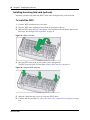
To install the patch panel...............................................................................................87
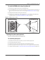
To install the BCM50 wall-mount bracket ......................................................................88
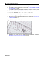
To install the BCM50 unit on the wall-mount bracket ....................................................90
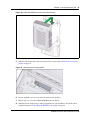
To install the WFC .........................................................................................................92
To install the BCM50 unit on a desktop or shelf ............................................................93
To install the power supply on the rack-mount shelf .....................................................94
To install the power supply on the desktop ...................................................................95
To install a power supply using the power supply mounting enclosure .........................95
To install a power supply using the single power supply mounting bracket ..................95
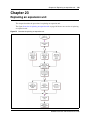
Installing an expansion unit . . . . . . . . . . . . . . . . . . . . . . . . . . . . . . . . . . . . . 97
To set G4x16 or G8x16 dip switches...........................................................................100
To set GASM dip switches ..........................................................................................100
To set GATM dip switches...........................................................................................101
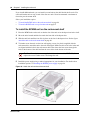
To install an MBM ........................................................................................................102
Connecting the cables to the BCM50 system . . . . . . . . . . . . . . . . . . . . . 105
To connect an expansion unit .....................................................................................107
To connect a power supply using a UPS.....................................................................109
To connect a power supply without a UPS ..................................................................109
To connect the lines and extensions ...........................................................................112
To connect telephone lines to DTM, BRIM, or 4x16 MBMs.........................................113
To connect analog telephone lines to the GATM4/GATM8 or G4x16/G8x16..............114
To connect extensions to DSM16, DSM32, ASM8, 4x16, G4x16, or G8x16 MBMs ...115
To install an auxiliary ringer .........................................................................................116
To install an external paging system ...........................................................................116
To connect the music source using the music source jack .........................................118
To connect the music source using the RJ-21 telephony connector ...........................118
To connect the cables to the wiring field card (optional) .............................................119
To connect the cables to the patch panel (optional) ....................................................119
Installation and Maintenance Guide
8
Task List
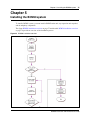
Installing telephones and peripherals . . . . . . . . . . . . . . . . . . . . . . . . . . . . 121
To install the emergency telephone.............................................................................122
Installing the analog terminal adapter . . . . . . . . . . . . . . . . . . . . . . . . . . . 123
To connect the ATA2...................................................................................................125
To mount the ATA2 on a wall ......................................................................................125
To measure the insertion loss from the CO to the analog device................................127
To measure the insertion loss from the analog device to the CO................................127
Configuring the BCM50 system . . . . . . . . . . . . . . . . . . . . . . . . . . . . . . . . . 129
Using Telset Administration to set the basic parameters . . . . . . . . . . . . 133
To enter the keycodes .................................................................................................134
To configure the IP address ........................................................................................135
To configure the modem..............................................................................................135
To select the region .....................................................................................................136
To select the telephony startup template and start DN ...............................................136
To initialize voice mail..................................................................................................136
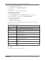
To create Telset user accounts ...................................................................................136
Using Element Manager to set the basic parameters . . . . . . . . . . . . . . . 139
To access the BCM50 Web page ................................................................................140
To download and install Element Manager .................................................................140
To connect to the BCM50 system using Element Manager ........................................140
To enter a keycode......................................................................................................141
To configure the LAN IP address ................................................................................141
To configure the modem..............................................................................................142
To configure the startup template for telephony services ...........................................142
To initialize voice mail..................................................................................................143
To enter a name for your system.................................................................................143
To configure the date and time settings ......................................................................143
To configure DHCP server settings ............................................................................144
To configure IP Phones ...............................................................................................145
To configure SNMP settings ........................................................................................146
To configure SNMP community strings .......................................................................147
To configure the SNMP manager list...........................................................................147
To create user accounts ..............................................................................................148
To configure SRG ........................................................................................................149
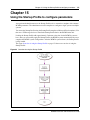
Using the Startup Profile to configure parameters . . . . . . . . . . . . . . . . . 151
To download the Startup Profile template ...................................................................153
To customize a Startup Profile for your system ..........................................................153
To load the Startup Profile data onto the BCM50 system ...........................................154
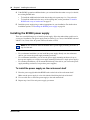
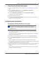
Completing the initial installation (optional) . . . . . . . . . . . . . . . . . . . . . . 157
To configure the MBM(s) .............................................................................................158
Connecting the BCM50 system to the LAN and WAN . . . . . . . . . . . . . . . 161
To connect the BCM50 system to the LAN .................................................................163
To connect the BCM50e or BCM50be main units to the WAN ....................................164
To connect the BCM50a or BCM50ba main units to the WAN ....................................164
NN40170-305
Task List
9
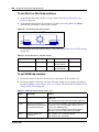
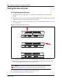
Testing basic BCM50 functionality . . . . . . . . . . . . . . . . . . . . . . . . . . . . . . 167
To test the main unit ....................................................................................................167
To troubleshoot the main unit ......................................................................................168
To test the expansion unit ...........................................................................................168
To troubleshoot the expansion unit .............................................................................168
To test the MBM ..........................................................................................................169
To test a station MBM..................................................................................................169
To test a trunk MBM ....................................................................................................169
To determine why an MBM does not appear in Element Manager .............................170
To determine why the ATA2 does not function............................................................170
To determine why there is no dial tone at the ATA2....................................................170
To check the ATA2 wiring............................................................................................171
To perform a Level 1 and Level 2 reset.......................................................................172
Replacing the BCM50 system components . . . . . . . . . . . . . . . . . . . . . . . 175
To shut down the system.............................................................................................176
To return the system to operation................................................................................176
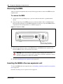
Replacing a power supply . . . . . . . . . . . . . . . . . . . . . . . . . . . . . . . . . . . . . 177
To remove the power supply .......................................................................................178
To connect the new power supply ...............................................................................179
Replacing a main unit . . . . . . . . . . . . . . . . . . . . . . . . . . . . . . . . . . . . . . . . . 181
To disconnect the cables.............................................................................................182
To remove a rack-mounted main unit ..........................................................................183
To remove a wall-mounted main unit ..........................................................................183
To remove a desktop mounted main unit ....................................................................183
To connect the cables .................................................................................................184
Replacing a media bay module . . . . . . . . . . . . . . . . . . . . . . . . . . . . . . . . . 185
To remove the MBM ....................................................................................................186
To insert the new MBM................................................................................................187
Replacing an expansion unit . . . . . . . . . . . . . . . . . . . . . . . . . . . . . . . . . . . 189
To disconnect the expansion unit cables.....................................................................190
To remove a rack-mounted expansion unit .................................................................191
To remove a wall-mounted expansion unit ..................................................................191
To remove a desktop-mounted expansion unit ...........................................................191
To remove the MBM ....................................................................................................192
To connect the cables .................................................................................................193
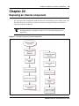
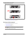
Replacing an internal component . . . . . . . . . . . . . . . . . . . . . . . . . . . . . . . 195
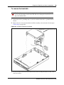
To open the main unit case .........................................................................................197
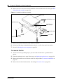
To remove the hard disk..............................................................................................199
To remove the fan .......................................................................................................200
To remove the router card ...........................................................................................201
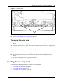
To insert the new hard disk .........................................................................................202
To insert the new fan ...................................................................................................204
To insert the new router card.......................................................................................205
To close the main unit case .........................................................................................206
RJ-21 telephony connector wiring chart . . . . . . . . . . . . . . . . . . . . . . . . . . 209
Installation and Maintenance Guide
10
Task List
BRI wiring chart . . . . . . . . . . . . . . . . . . . . . . . . . . . . . . . . . . . . . . . . . . . . . . 213
LAN ports wiring chart . . . . . . . . . . . . . . . . . . . . . . . . . . . . . . . . . . . . . . . . 215
WAN ports wiring chart . . . . . . . . . . . . . . . . . . . . . . . . . . . . . . . . . . . . . . . 217
Expansion ports wiring chart . . . . . . . . . . . . . . . . . . . . . . . . . . . . . . . . . . . 219
DTM wiring chart . . . . . . . . . . . . . . . . . . . . . . . . . . . . . . . . . . . . . . . . . . . . . 221
BRIM wiring chart . . . . . . . . . . . . . . . . . . . . . . . . . . . . . . . . . . . . . . . . . . . . 223
ADID wiring chart . . . . . . . . . . . . . . . . . . . . . . . . . . . . . . . . . . . . . . . . . . . . 225
GATM wiring chart . . . . . . . . . . . . . . . . . . . . . . . . . . . . . . . . . . . . . . . . . . . 227
4x16 wiring charts . . . . . . . . . . . . . . . . . . . . . . . . . . . . . . . . . . . . . . . . . . . . 231
G4x16 and G8x16 wiring charts . . . . . . . . . . . . . . . . . . . . . . . . . . . . . . . . . 235
DSM16 and DSM32 wiring charts . . . . . . . . . . . . . . . . . . . . . . . . . . . . . . . 239
ASM8, ASM8+, and GASM wiring chart . . . . . . . . . . . . . . . . . . . . . . . . . . 243
Market profile attributes . . . . . . . . . . . . . . . . . . . . . . . . . . . . . . . . . . . . . . . 245
NN40170-305
11
Contents
New in this release. . . . . . . . . . . . . . . . . . . . . . . . . . . . . . . . . . . . . . . . . . . . . 19
Features . . . . . . . . . . . . . . . . . . . . . . . . . . . . . . . . . . . . . . . . . . . . . . . . . . . . . . . . . . . 19
Regulatory information . . . . . . . . . . . . . . . . . . . . . . . . . . . . . . . . . . . . . . . . . 21
North American regulatory information . . . . . . . . . . . . . . . . . . . . . . . . . . . . . . . . . . . . 21
Canadian Notice . . . . . . . . . . . . . . . . . . . . . . . . . . . . . . . . . . . . . . . . . . . . . . . . . . 21
Federal Communications Commission (FCC) Notice . . . . . . . . . . . . . . . . . . . . . . 22
Ringer Equivalence Number (REN) . . . . . . . . . . . . . . . . . . . . . . . . . . . . . . . . . . . 22
EMI/EMC (FCC Part 15) . . . . . . . . . . . . . . . . . . . . . . . . . . . . . . . . . . . . . . . . . . . . 22
Important safety instructions . . . . . . . . . . . . . . . . . . . . . . . . . . . . . . . . . . . . . . . . . 23
Safety . . . . . . . . . . . . . . . . . . . . . . . . . . . . . . . . . . . . . . . . . . . . . . . . . . . . . . . . . . 24
Enhanced 911 configuration . . . . . . . . . . . . . . . . . . . . . . . . . . . . . . . . . . . . . . . . . 25
Radio-frequency interference . . . . . . . . . . . . . . . . . . . . . . . . . . . . . . . . . . . . . . . . 25
Telecommunication registration . . . . . . . . . . . . . . . . . . . . . . . . . . . . . . . . . . . . . . 25
International regulatory information . . . . . . . . . . . . . . . . . . . . . . . . . . . . . . . . . . . . . . . 26
Safety . . . . . . . . . . . . . . . . . . . . . . . . . . . . . . . . . . . . . . . . . . . . . . . . . . . . . . . . . . 27
Additional safety information . . . . . . . . . . . . . . . . . . . . . . . . . . . . . . . . . . . . . . . . . 27
ITU standardization compliance . . . . . . . . . . . . . . . . . . . . . . . . . . . . . . . . . . . . . . 28
Chapter 1
Getting started . . . . . . . . . . . . . . . . . . . . . . . . . . . . . . . . . . . . . . . . . . . . . . . . 29
About this guide . . . . . . . . . . . . . . . . . . . . . . . . . . . . . . . . . . . . . . . . . . . . . . . . . . . . . . 29
Audience . . . . . . . . . . . . . . . . . . . . . . . . . . . . . . . . . . . . . . . . . . . . . . . . . . . . . . . . . . . 29
Acronyms . . . . . . . . . . . . . . . . . . . . . . . . . . . . . . . . . . . . . . . . . . . . . . . . . . . . . . . . . . . 29
Symbols and text conventions . . . . . . . . . . . . . . . . . . . . . . . . . . . . . . . . . . . . . . . . . . . 31
Related publications . . . . . . . . . . . . . . . . . . . . . . . . . . . . . . . . . . . . . . . . . . . . . . . . . . 33
How to get help . . . . . . . . . . . . . . . . . . . . . . . . . . . . . . . . . . . . . . . . . . . . . . . . . . . . . . 34
Chapter 2
Introducing the BCM50 hardware. . . . . . . . . . . . . . . . . . . . . . . . . . . . . . . . . 37
Main units . . . . . . . . . . . . . . . . . . . . . . . . . . . . . . . . . . . . . . . . . . . . . . . . . . . . . . . . . . 37
BCM50 Expansion unit and media bay modules . . . . . . . . . . . . . . . . . . . . . . . . . . . . . 42
Media bay modules . . . . . . . . . . . . . . . . . . . . . . . . . . . . . . . . . . . . . . . . . . . . . . . . 44
BCM50 hardware . . . . . . . . . . . . . . . . . . . . . . . . . . . . . . . . . . . . . . . . . . . . . . . . . . . . . 52
Rack-mount shelf . . . . . . . . . . . . . . . . . . . . . . . . . . . . . . . . . . . . . . . . . . . . . . . . . 52
Patch panel . . . . . . . . . . . . . . . . . . . . . . . . . . . . . . . . . . . . . . . . . . . . . . . . . . . . . . 53
Wall-mount bracket . . . . . . . . . . . . . . . . . . . . . . . . . . . . . . . . . . . . . . . . . . . . . . . . 53
Power supply mounting bracket and enclosure . . . . . . . . . . . . . . . . . . . . . . . . . . 54
Wiring field card . . . . . . . . . . . . . . . . . . . . . . . . . . . . . . . . . . . . . . . . . . . . . . . . . . 54
BCM50 Installation and Maintenance Guide
12
Contents
BCM50 components . . . . . . . . . . . . . . . . . . . . . . . . . . . . . . . . . . . . . . . . . . . . . . . . . . 54
Power supply . . . . . . . . . . . . . . . . . . . . . . . . . . . . . . . . . . . . . . . . . . . . . . . . . . . . . 55
Power supply adapter cord (international users) . . . . . . . . . . . . . . . . . . . . . . . . . . 55
Uninterruptable power supply . . . . . . . . . . . . . . . . . . . . . . . . . . . . . . . . . . . . . . . . 55
Hard disk . . . . . . . . . . . . . . . . . . . . . . . . . . . . . . . . . . . . . . . . . . . . . . . . . . . . . . . . 56
Cooling fan . . . . . . . . . . . . . . . . . . . . . . . . . . . . . . . . . . . . . . . . . . . . . . . . . . . . . . 57
RJ-21 telephony connector . . . . . . . . . . . . . . . . . . . . . . . . . . . . . . . . . . . . . . . . . . 58
Router card . . . . . . . . . . . . . . . . . . . . . . . . . . . . . . . . . . . . . . . . . . . . . . . . . . . . . . 59
Field-replaceable units . . . . . . . . . . . . . . . . . . . . . . . . . . . . . . . . . . . . . . . . . . . . . . . . 59
Accessories . . . . . . . . . . . . . . . . . . . . . . . . . . . . . . . . . . . . . . . . . . . . . . . . . . . . . . 60
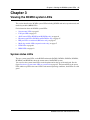
Chapter 3
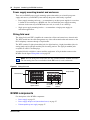
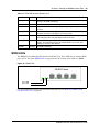
Viewing the BCM50 system LEDs . . . . . . . . . . . . . . . . . . . . . . . . . . . . . . . . 61
System status LEDs . . . . . . . . . . . . . . . . . . . . . . . . . . . . . . . . . . . . . . . . . . . . . . . . . . 61
LAN port LEDs . . . . . . . . . . . . . . . . . . . . . . . . . . . . . . . . . . . . . . . . . . . . . . . . . . . . . . . 63
ADSL router LEDs (BCM50a and BCM50ba only) . . . . . . . . . . . . . . . . . . . . . . . . . . . 64
Ethernet router LEDs (BCM50e and BCM50be only) . . . . . . . . . . . . . . . . . . . . . . . . . 65
BRI port LEDs on main unit (BRI series only) . . . . . . . . . . . . . . . . . . . . . . . . . . . . . . . 67
Media bay module LEDs (expansion units only) . . . . . . . . . . . . . . . . . . . . . . . . . . . . . 67
DTM LEDs . . . . . . . . . . . . . . . . . . . . . . . . . . . . . . . . . . . . . . . . . . . . . . . . . . . . . . . . . . 68
BRIM LEDs . . . . . . . . . . . . . . . . . . . . . . . . . . . . . . . . . . . . . . . . . . . . . . . . . . . . . . . . . 69
Chapter 4
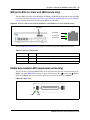
Determining DHCP server configuration and IP address. . . . . . . . . . . . . . 71
BCM50 and BCM50b main units (no integrated router) . . . . . . . . . . . . . . . . . . . . . . . 71
If an external DHCP server is not present . . . . . . . . . . . . . . . . . . . . . . . . . . . . . . . 71
If an external DHCP server is present . . . . . . . . . . . . . . . . . . . . . . . . . . . . . . . . . . 72
BCM50a, BCM50ba, BCM50e, and BCM50be main units
(with integrated router) . . . . . . . . . . . . . . . . . . . . . . . . . . . . . . . . . . . . . . . . . . . . . . . 72
Chapter 5
Installing the BCM50 system . . . . . . . . . . . . . . . . . . . . . . . . . . . . . . . . . . . . 75
Chapter 6
Checking the installation prerequisites . . . . . . . . . . . . . . . . . . . . . . . . . . . . 79
Environmental requirements . . . . . . . . . . . . . . . . . . . . . . . . . . . . . . . . . . . . . . . . . . . . 79
Electrical requirements . . . . . . . . . . . . . . . . . . . . . . . . . . . . . . . . . . . . . . . . . . . . . . . . 79
Site telephony wiring requirements . . . . . . . . . . . . . . . . . . . . . . . . . . . . . . . . . . . . . . . 80
Digital loop . . . . . . . . . . . . . . . . . . . . . . . . . . . . . . . . . . . . . . . . . . . . . . . . . . . . . . 80
Analog loop . . . . . . . . . . . . . . . . . . . . . . . . . . . . . . . . . . . . . . . . . . . . . . . . . . . . . . 80
System equipment, supplies, and tools . . . . . . . . . . . . . . . . . . . . . . . . . . . . . . . . . . . . 81
Basic hardware . . . . . . . . . . . . . . . . . . . . . . . . . . . . . . . . . . . . . . . . . . . . . . . . . . . 81
Optional equipment . . . . . . . . . . . . . . . . . . . . . . . . . . . . . . . . . . . . . . . . . . . . . . . . 81
NN40170-305
Contents
13
Other hardware and tools . . . . . . . . . . . . . . . . . . . . . . . . . . . . . . . . . . . . . . . . . . . 81
Chapter 7
Installing the main unit . . . . . . . . . . . . . . . . . . . . . . . . . . . . . . . . . . . . . . . . . 83
Unpacking the main unit . . . . . . . . . . . . . . . . . . . . . . . . . . . . . . . . . . . . . . . . . . . . . . . 84
Installing the BCM50 unit in an equipment rack . . . . . . . . . . . . . . . . . . . . . . . . . . . . . 84
Installing the BCM50 unit on the rack-mount shelf . . . . . . . . . . . . . . . . . . . . . . . . 85
Installing the patch panel (optional) . . . . . . . . . . . . . . . . . . . . . . . . . . . . . . . . . . . 87
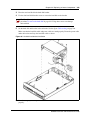
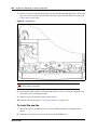
Installing the BCM50 unit on the wall . . . . . . . . . . . . . . . . . . . . . . . . . . . . . . . . . . . . . 88
Installing the wiring field card (optional) . . . . . . . . . . . . . . . . . . . . . . . . . . . . . . . . 92
Installing the BCM50 unit on a desktop or shelf . . . . . . . . . . . . . . . . . . . . . . . . . . . . . 93
Installing the BCM50 power supply . . . . . . . . . . . . . . . . . . . . . . . . . . . . . . . . . . . . . . . 94
Next step . . . . . . . . . . . . . . . . . . . . . . . . . . . . . . . . . . . . . . . . . . . . . . . . . . . . . . . . . . . 95
Chapter 8
Installing an expansion unit . . . . . . . . . . . . . . . . . . . . . . . . . . . . . . . . . . . . . 97
Unpacking the expansion unit . . . . . . . . . . . . . . . . . . . . . . . . . . . . . . . . . . . . . . . . . . . 98
Verifying the media bay module switch settings . . . . . . . . . . . . . . . . . . . . . . . . . . . . . 98
Installing a media bay module in an expansion unit
. . . . . . . . . . . . . . . . . . . . . . . . 102
Installing the expansion unit . . . . . . . . . . . . . . . . . . . . . . . . . . . . . . . . . . . . . . . . . . . 103
Next step . . . . . . . . . . . . . . . . . . . . . . . . . . . . . . . . . . . . . . . . . . . . . . . . . . . . . . . . . . 103
Chapter 9
Connecting the cables to the BCM50 system . . . . . . . . . . . . . . . . . . . . . . 105
Connecting the expansion unit . . . . . . . . . . . . . . . . . . . . . . . . . . . . . . . . . . . . . . . . . 106
Connecting the power supply . . . . . . . . . . . . . . . . . . . . . . . . . . . . . . . . . . . . . . . . . . 108
Connecting the lines and extensions . . . . . . . . . . . . . . . . . . . . . . . . . . . . . . . . . . . . . 110
Wiring warnings . . . . . . . . . . . . . . . . . . . . . . . . . . . . . . . . . . . . . . . . . . . . . . . . . . 111
Connecting lines and extensions to the RJ-21 telephony connector . . . . . . . . . 112
Connecting telephone lines to the expansion units . . . . . . . . . . . . . . . . . . . . . . . 113
Connecting extensions to the expansion units . . . . . . . . . . . . . . . . . . . . . . . . . . 114
Connecting the auxiliary equipment . . . . . . . . . . . . . . . . . . . . . . . . . . . . . . . . . . . . . 115
Connecting an auxiliary ringer . . . . . . . . . . . . . . . . . . . . . . . . . . . . . . . . . . . . . . . 116
Connecting an external paging system . . . . . . . . . . . . . . . . . . . . . . . . . . . . . . . . 116
Connecting an external music source . . . . . . . . . . . . . . . . . . . . . . . . . . . . . . . . . 117
Next step . . . . . . . . . . . . . . . . . . . . . . . . . . . . . . . . . . . . . . . . . . . . . . . . . . . . . . . . . . 120
Chapter 10
Installing telephones and peripherals . . . . . . . . . . . . . . . . . . . . . . . . . . . . 121
System telephones . . . . . . . . . . . . . . . . . . . . . . . . . . . . . . . . . . . . . . . . . . . . . . . . . . 121
Analog terminal adapter 2 . . . . . . . . . . . . . . . . . . . . . . . . . . . . . . . . . . . . . . . . . . 121
Installing an emergency telephone . . . . . . . . . . . . . . . . . . . . . . . . . . . . . . . . . . . . . . 122
Installing IP phones . . . . . . . . . . . . . . . . . . . . . . . . . . . . . . . . . . . . . . . . . . . . . . . . . . 122
BCM50 Installation and Maintenance Guide
14
Contents
Chapter 11
Installing the analog terminal adapter . . . . . . . . . . . . . . . . . . . . . . . . . . . . 123
Configuration overview . . . . . . . . . . . . . . . . . . . . . . . . . . . . . . . . . . . . . . . . . . . . . . . 123
Analog telephone . . . . . . . . . . . . . . . . . . . . . . . . . . . . . . . . . . . . . . . . . . . . . . . . 123
Analog data device . . . . . . . . . . . . . . . . . . . . . . . . . . . . . . . . . . . . . . . . . . . . . . . 124
Installing the ATA2 . . . . . . . . . . . . . . . . . . . . . . . . . . . . . . . . . . . . . . . . . . . . . . . . . . 124
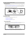
Connecting the ATA2 . . . . . . . . . . . . . . . . . . . . . . . . . . . . . . . . . . . . . . . . . . . . . 124
Mounting the ATA2 . . . . . . . . . . . . . . . . . . . . . . . . . . . . . . . . . . . . . . . . . . . . . . . 125
Test insertion loss measurement . . . . . . . . . . . . . . . . . . . . . . . . . . . . . . . . . . . . 126
Configuring the ATA2 . . . . . . . . . . . . . . . . . . . . . . . . . . . . . . . . . . . . . . . . . . . . . . . . 127
Chapter 12
Configuring the BCM50 system . . . . . . . . . . . . . . . . . . . . . . . . . . . . . . . . . 129
Initial parameters overview . . . . . . . . . . . . . . . . . . . . . . . . . . . . . . . . . . . . . . . . . . . . 130
Startup parameters overview . . . . . . . . . . . . . . . . . . . . . . . . . . . . . . . . . . . . . . . . . . . 131
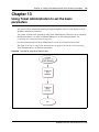
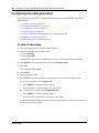
Chapter 13
Using Telset Administration to set the basic parameters . . . . . . . . . . . . 133
Configuring the initial parameters . . . . . . . . . . . . . . . . . . . . . . . . . . . . . . . . . . . . . . . 134
Next step . . . . . . . . . . . . . . . . . . . . . . . . . . . . . . . . . . . . . . . . . . . . . . . . . . . . . . . . . . 137
Chapter 14
Using Element Manager to set the basic parameters. . . . . . . . . . . . . . . . 139
Prerequisites . . . . . . . . . . . . . . . . . . . . . . . . . . . . . . . . . . . . . . . . . . . . . . . . . . . . . . . 140
Accessing the BCM50 system . . . . . . . . . . . . . . . . . . . . . . . . . . . . . . . . . . . . . . . . . . 140
Configuring the initial parameters . . . . . . . . . . . . . . . . . . . . . . . . . . . . . . . . . . . . . . . 141
Configuring the startup parameters . . . . . . . . . . . . . . . . . . . . . . . . . . . . . . . . . . . . . . 143
Next step . . . . . . . . . . . . . . . . . . . . . . . . . . . . . . . . . . . . . . . . . . . . . . . . . . . . . . . . . . 149
Chapter 15
Using the Startup Profile to configure parameters. . . . . . . . . . . . . . . . . . 151
Startup Profile requirements . . . . . . . . . . . . . . . . . . . . . . . . . . . . . . . . . . . . . . . . . . . 152
Configuring basic parameters . . . . . . . . . . . . . . . . . . . . . . . . . . . . . . . . . . . . . . . . . . 153
Next step . . . . . . . . . . . . . . . . . . . . . . . . . . . . . . . . . . . . . . . . . . . . . . . . . . . . . . . . . . 155
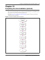
Chapter 16
Completing the initial installation (optional) . . . . . . . . . . . . . . . . . . . . . . . 157
Configuring the media bay module . . . . . . . . . . . . . . . . . . . . . . . . . . . . . . . . . . . . . . 158
Configuring modem settings . . . . . . . . . . . . . . . . . . . . . . . . . . . . . . . . . . . . . . . . . . . 159
Checking for software updates . . . . . . . . . . . . . . . . . . . . . . . . . . . . . . . . . . . . . . . . . 159
Configuring voice mail . . . . . . . . . . . . . . . . . . . . . . . . . . . . . . . . . . . . . . . . . . . . . . . . 159
Customizing security policies . . . . . . . . . . . . . . . . . . . . . . . . . . . . . . . . . . . . . . . . . . 160
Performing a backup . . . . . . . . . . . . . . . . . . . . . . . . . . . . . . . . . . . . . . . . . . . . . . . . . 160
NN40170-305
Contents
15
Chapter 17
Connecting the BCM50 system to the LAN and WAN . . . . . . . . . . . . . . . 161
Connecting the BCM50 system to the LAN . . . . . . . . . . . . . . . . . . . . . . . . . . . . . . . . 162
Connecting the BCM50 system to the WAN . . . . . . . . . . . . . . . . . . . . . . . . . . . . . . . 163
Next step . . . . . . . . . . . . . . . . . . . . . . . . . . . . . . . . . . . . . . . . . . . . . . . . . . . . . . . . . . 165
Chapter 18
Testing basic BCM50 functionality. . . . . . . . . . . . . . . . . . . . . . . . . . . . . . . 167
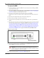
Reset to factory settings . . . . . . . . . . . . . . . . . . . . . . . . . . . . . . . . . . . . . . . . . . . . . . 171
Reset levels . . . . . . . . . . . . . . . . . . . . . . . . . . . . . . . . . . . . . . . . . . . . . . . . . . . . . 171
Activate the reset feature . . . . . . . . . . . . . . . . . . . . . . . . . . . . . . . . . . . . . . . . . . 172
Chapter 19
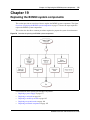
Replacing the BCM50 system components. . . . . . . . . . . . . . . . . . . . . . . . 175
Preparing the system for maintenance . . . . . . . . . . . . . . . . . . . . . . . . . . . . . . . . . . . 176
Restarting the system after maintenance . . . . . . . . . . . . . . . . . . . . . . . . . . . . . . . . . 176
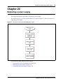
Chapter 20
Replacing a power supply. . . . . . . . . . . . . . . . . . . . . . . . . . . . . . . . . . . . . . 177
Preparing the system for maintenance . . . . . . . . . . . . . . . . . . . . . . . . . . . . . . . . . . . 178
Removing the power supply . . . . . . . . . . . . . . . . . . . . . . . . . . . . . . . . . . . . . . . . . . . 178
Connect the new power supply . . . . . . . . . . . . . . . . . . . . . . . . . . . . . . . . . . . . . . . . . 178
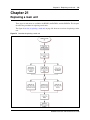
Chapter 21
Replacing a main unit . . . . . . . . . . . . . . . . . . . . . . . . . . . . . . . . . . . . . . . . . 181
Preparing the system for maintenance . . . . . . . . . . . . . . . . . . . . . . . . . . . . . . . . . . . 182
Removing the main unit . . . . . . . . . . . . . . . . . . . . . . . . . . . . . . . . . . . . . . . . . . . . . . . 182
Installing the new main unit . . . . . . . . . . . . . . . . . . . . . . . . . . . . . . . . . . . . . . . . . . . . 183
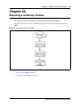
Chapter 22
Replacing a media bay module. . . . . . . . . . . . . . . . . . . . . . . . . . . . . . . . . . 185
Chapter 23
Replacing an expansion unit . . . . . . . . . . . . . . . . . . . . . . . . . . . . . . . . . . . 189
Disconnecting the cables . . . . . . . . . . . . . . . . . . . . . . . . . . . . . . . . . . . . . . . . . . . . . . 190
Removing the expansion unit . . . . . . . . . . . . . . . . . . . . . . . . . . . . . . . . . . . . . . . . . . 190
Removing the MBM . . . . . . . . . . . . . . . . . . . . . . . . . . . . . . . . . . . . . . . . . . . . . . . . . . 192
Inserting the MBM in the new expansion unit . . . . . . . . . . . . . . . . . . . . . . . . . . . . . . 192
Installing the new expansion unit . . . . . . . . . . . . . . . . . . . . . . . . . . . . . . . . . . . . . . . . 193
Chapter 24
Replacing an internal component . . . . . . . . . . . . . . . . . . . . . . . . . . . . . . . 195
Special tools . . . . . . . . . . . . . . . . . . . . . . . . . . . . . . . . . . . . . . . . . . . . . . . . . . . . . . . 196
Preparing the system for maintenance . . . . . . . . . . . . . . . . . . . . . . . . . . . . . . . . . . . 196
BCM50 Installation and Maintenance Guide
16
Contents
Removing the main unit . . . . . . . . . . . . . . . . . . . . . . . . . . . . . . . . . . . . . . . . . . . . . . . 196
Opening the main unit case . . . . . . . . . . . . . . . . . . . . . . . . . . . . . . . . . . . . . . . . . . . . 196
Removing an internal component . . . . . . . . . . . . . . . . . . . . . . . . . . . . . . . . . . . . . . . 198
Inserting the new component . . . . . . . . . . . . . . . . . . . . . . . . . . . . . . . . . . . . . . . . . . 201
Closing the main unit case . . . . . . . . . . . . . . . . . . . . . . . . . . . . . . . . . . . . . . . . . . . . 206
Installing the main unit . . . . . . . . . . . . . . . . . . . . . . . . . . . . . . . . . . . . . . . . . . . . . . . . 207
Connecting the cables . . . . . . . . . . . . . . . . . . . . . . . . . . . . . . . . . . . . . . . . . . . . . . . . 207
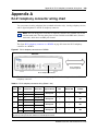
Appendix A
RJ-21 telephony connector wiring chart . . . . . . . . . . . . . . . . . . . . . . . . . . 209
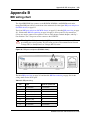
Appendix B
BRI wiring chart . . . . . . . . . . . . . . . . . . . . . . . . . . . . . . . . . . . . . . . . . . . . . . 213
Appendix C
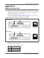
LAN ports wiring chart . . . . . . . . . . . . . . . . . . . . . . . . . . . . . . . . . . . . . . . . 215
Appendix D
WAN ports wiring chart . . . . . . . . . . . . . . . . . . . . . . . . . . . . . . . . . . . . . . . . 217
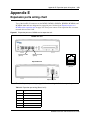
Appendix E
Expansion ports wiring chart . . . . . . . . . . . . . . . . . . . . . . . . . . . . . . . . . . . 219
Appendix F
DTM wiring chart . . . . . . . . . . . . . . . . . . . . . . . . . . . . . . . . . . . . . . . . . . . . . 221
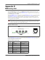
Appendix G
BRIM wiring chart. . . . . . . . . . . . . . . . . . . . . . . . . . . . . . . . . . . . . . . . . . . . . 223
Appendix H
ADID wiring chart . . . . . . . . . . . . . . . . . . . . . . . . . . . . . . . . . . . . . . . . . . . . . 225
Appendix I
GATM wiring chart . . . . . . . . . . . . . . . . . . . . . . . . . . . . . . . . . . . . . . . . . . . . 227
Appendix J
4x16 wiring charts . . . . . . . . . . . . . . . . . . . . . . . . . . . . . . . . . . . . . . . . . . . . 231
Appendix K
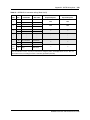
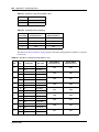
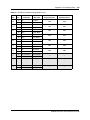
G4x16 and G8x16 wiring charts . . . . . . . . . . . . . . . . . . . . . . . . . . . . . . . . . 235
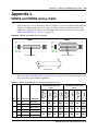
Appendix L
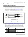
DSM16 and DSM32 wiring charts . . . . . . . . . . . . . . . . . . . . . . . . . . . . . . . . 239
Appendix M
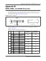
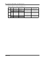
ASM8, ASM8+, and GASM wiring chart . . . . . . . . . . . . . . . . . . . . . . . . . . . 243
Appendix N
NN40170-305
Contents
17
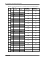
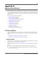
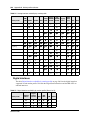
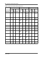
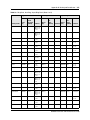
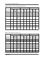
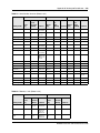
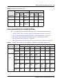
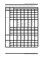
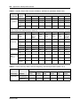
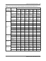
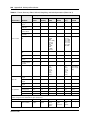
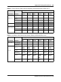
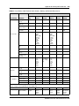
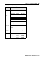
Market profile attributes . . . . . . . . . . . . . . . . . . . . . . . . . . . . . . . . . . . . . . . 245
Interface availability . . . . . . . . . . . . . . . . . . . . . . . . . . . . . . . . . . . . . . . . . . . . . . . . . . 245
Analog interfaces . . . . . . . . . . . . . . . . . . . . . . . . . . . . . . . . . . . . . . . . . . . . . . . . 245
Digital interfaces . . . . . . . . . . . . . . . . . . . . . . . . . . . . . . . . . . . . . . . . . . . . . . . . . 246
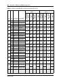
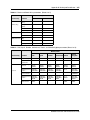
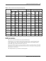
Tones and cadences . . . . . . . . . . . . . . . . . . . . . . . . . . . . . . . . . . . . . . . . . . . . . . . . . 247
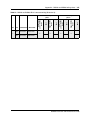
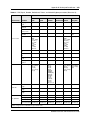
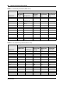
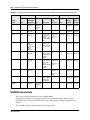
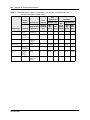
Core parameters for market profiles . . . . . . . . . . . . . . . . . . . . . . . . . . . . . . . . . . . . . 255
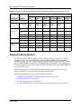
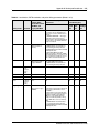
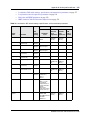
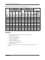
Analog Trunk parameters . . . . . . . . . . . . . . . . . . . . . . . . . . . . . . . . . . . . . . . . . . . . . 270
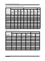
GASM8 parameters . . . . . . . . . . . . . . . . . . . . . . . . . . . . . . . . . . . . . . . . . . . . . . . . . . 276
GASI parameters . . . . . . . . . . . . . . . . . . . . . . . . . . . . . . . . . . . . . . . . . . . . . . . . . . . . 279
ATA2 parameters . . . . . . . . . . . . . . . . . . . . . . . . . . . . . . . . . . . . . . . . . . . . . . . . . . . 281
ATA2 DR6 . . . . . . . . . . . . . . . . . . . . . . . . . . . . . . . . . . . . . . . . . . . . . . . . . . . . . . 281
ATA2 DR7 . . . . . . . . . . . . . . . . . . . . . . . . . . . . . . . . . . . . . . . . . . . . . . . . . . . . . . 283
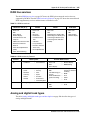
Voicemail . . . . . . . . . . . . . . . . . . . . . . . . . . . . . . . . . . . . . . . . . . . . . . . . . . . . . . . . . . 284
ISDN line services . . . . . . . . . . . . . . . . . . . . . . . . . . . . . . . . . . . . . . . . . . . . . . . . . . . 287
Analog and digital trunk types . . . . . . . . . . . . . . . . . . . . . . . . . . . . . . . . . . . . . . . . . . 287
Index . . . . . . . . . . . . . . . . . . . . . . . . . . . . . . . . . . . . . . . . . . . . . . . . . . . . . . . 291
BCM50 Installation and Maintenance Guide
18
Contents
NN40170-305
New in this release
19
New in this release
The following sections detail what’s new in Business Communications Manager 50 Installation
and Maintenance for release 5.0.
•
Features on page 19
Features
This release contains no new features.
BCM50 Installation and Maintenance Guide
20
New in this release
NN40170-305
21
Regulatory information
For regulatory information about the BCM50 system:
•
•
“North American regulatory information”
“International regulatory information” on page 26
North American regulatory information
This Class A device complies with Part 68 and Part 15 of the FCC Rules and ICES-003 Class A
Canadian EMI requirements. Operation is subject to the following two conditions (1) This device
may not cause harmful interference and (2) this device must accept any interference received,
including interference that may cause undesired operation.
Repairs to certified equipment should be coordinated by a representative designated by the
supplier. Any repairs or alterations made by the user to this equipment, or equipment
malfunctions, may give the telecommunications company cause to request the user to disconnect
the equipment. Users should ensure for their own protection that the electrical ground connections
of the power utility, telephone lines, and internal metallic water pipe system, if present, are
connected together. This precaution may be particularly important in rural areas.
Caution: Users should not attempt to make such connections themselves, but
should contact the appropriate electric inspection authority, or electrician, as
appropriate.
Do not attempt to repair this equipment. If you experience trouble, write for warranty and repair
information:
USA
Canada
Nortel
640 Massman Drive
Nashville, TN, USA
37210
Nortel Repair Service Centre 30
30 Norelco Drive
Weston Ontario, Canada
M9L 2X6
For warranty and repair service outside the USA or Canada, please contact your distributor.
Canadian Notice
The Industry Canada designation identifies certified equipment. This certification means that the
equipment meets telecommunications network protective, operational and safety requirements as
prescribed in the appropriate Terminal Equipment Technical Requirements document(s). The
Department does not guarantee the equipment will operate to the user's satisfaction.
BCM50 Installation and Maintenance Guide
22
Regulatory information
Federal Communications Commission (FCC) Notice
FCC registration number: This telephone equipment complies with Part 68, Rules and
Regulations, of the FCC for connection to the Public Switched Telephone Network.
Your connection to the Public Switched Telephone Network must comply with these FCC rules:
•
•
•
Before installing this equipment, users should ensure that it is permissible to be connected to
the facilities of the local telecommunications company. The equipment must also be installed
using an acceptable method of connection. The customer should be aware that compliance
with the preceding conditions may not prevent degradation of service in some situations. See
installation instructions for details.
Use only an FCC Part 68-compliant Universal Service Order Code (USOC) network interface
jack, as specified in the installation instructions, to connect to the Public Switched Telephone
Network.
If the equipment causes harm to the telephone network, the telephone company will notify you
in advance that temporary discontinuance of the product may be required. But if advance
notice isn’t practical, the telephone company will notify you as soon as possible. You will also
be advised of your right to file a complaint with the FCC, if you believe it is necessary.
Ringer Equivalence Number (REN)
The REN provides an indication of the maximum number of terminals allowed to be connected to
a telephone interface. The termination on an interface may consist of any combination of devices
subject only to the requirement that the sum of the RENs of all the devices does not exceed 5.
EMI/EMC (FCC Part 15)
This equipment has been tested and found to comply with the limits for a Class A digital device,
pursuant to Part 15 of the FCC Rules. These limits are designed to provide reasonable protection
against harmful interference in a residential installation. This equipment generates, uses and can
radiate radio frequency energy and, if not installed and used in accordance with the instructions,
may cause harmful interference to radio communications. However, there is no guarantee that
interference will not occur in a particular installation. If this equipment does cause harmful
interference to radio or television reception, which can be determined by turning the equipment off
and on, the user is encouraged to try to correct the interference by one or more of the following
measures:
•
•
•
•
Reorient or relocate the receiving antenna.
Increase the separation between the equipment and receiver.
Connect the equipment into an outlet on a circuit different from that to which the receiver is
connected.
Consult the dealer or an experienced radio/TV technician for help.
Changes or modifications not expressly approved by the party responsible for compliance could
void the user’s authority to operate the equipment.
NN40170-305
Regulatory information
23
Important safety instructions
The following safety instructions cover the installation and use of the Product. Read carefully and
retain for future reference.
Installation
Warning: To avoid electrical shock hazard to personnel or equipment damage
observe the following precautions when installing telephone equipment:
• Never install telephone wiring during a lightning storm.
• Never install telephone jacks in wet locations unless the jack is
specifically designed for wet locations.
• Never touch uninsulated telephone wires or terminals unless the
telephone line has been disconnected at the network interface.
Use caution when installing or modifying telephone lines. The exclamation
point within an equilateral triangle is intended to alert the user to the
presence of important operating and maintenance (servicing) instructions
in the literature accompanying the product.
Use
When using your telephone equipment, basic safety precautions should always be followed to
reduce risk of fire, electric shock and injury to persons, including the following:
1
Read and understand all instructions.
2
Follow the instructions marked on the product.
3
Unplug this product (or host equipment) from the wall outlet before cleaning. Do not use
liquid cleaners or aerosol cleaners. Use a damp cloth for cleaning.
4
Do not use this product near water, for example, near a bath tub, wash bowl, kitchen sink, or
laundry tub, in a wet basement, or near a swimming pool.
5
Do not place this product on an unstable cart, stand or table. The product may fall, causing
serious damage to the product.
6
This product should never be placed near or over a radiator or heat register. This product
should not be placed in a built-in installation unless proper ventilation is provided.
7
Do not allow anything to rest on the power cord. Do not locate this product where the cord will
be abused by persons walking on it.
8
Do not overload wall outlets and extension cords as this can result in the risk of fire or electric
shock.
9
Never spill liquid of any kind on the product.
10 To reduce the risk of electric shock do not disassemble this product, but send it to a qualified
service person when some service or repair work is required.
BCM50 Installation and Maintenance Guide
24
Regulatory information
11 Unplug this product (or host equipment) from the wall outlet and refer servicing to qualified
service personnel under the following conditions:
a
When the power supply cord or plug is damaged or frayed.
b
If the product has been exposed to rain, water or liquid has been spilled on the product,
disconnect and allow the product to dry out to see if it still operates; but do not open up the
product.
c
If the product housing has been damaged.
d
If the product exhibits a distinct change in performance.
Caution: To eliminate the possibility of accidental damage to cords, plugs, jacks,
and the telephone, do not use sharp instruments during the assembly procedures.
Warning: Do not insert the plug at the free end of the handset cord directly into a
wall or baseboard jack. Such misuse can result in unsafe sound levels or possible
damage to the handset.
12 Save these instructions.
Use of a music source
In accordance with U.S. Copyright Law, a license may be required from the American Society of
Composers, Authors and Publishers, or similar organization if Radio or TV broadcasts are
transmitted through the Music On Hold or Background Music features of this telecommunication
system.
Nortel hereby disclaims any liability arising out of the failure to obtain such a license.
Safety
Business Communications Manager 50 (BCM50) equipment meets all applicable requirements of
both the CSA C22.2 No.60950 and UL 60950 Edition 3.
Danger: Risk of shock.
Read and follow installation instructions carefully.
Ensure the BCM50 is not powered and that all telephone/data cables are removed prior to
opening the BCM50 unit in the field.
If installation of additional hardware and /or servicing is required, disconnect all telephone
cable connections prior to unplugging the BCM50 modules.
Ensure the BCM50 is connected to a wall outlet with a third-wire protective earth
connection prior to connecting any telecommunications cables to the BCM50 main unit or
expansion units.
NN40170-305
Regulatory information
25
Caution: Only qualified persons should service the system.
The installation and service of this hardware is to be performed only by service personnel
having appropriate training and experience necessary to be aware of hazards to which they
are exposed in performing a task and of measures to minimize the danger to themselves or
other persons.
Electrical shock hazards from the telecommunication network and AC mains are possible
with this equipment. To minimize risk to service personnel and users, the BCM50 system
must be connected to an outlet with a third-wire ground.
Service personnel must be alert to the possibility of high leakage currents becoming
available on metal system surfaces during power line fault events near network lines.
These leakage currents normally safely flow to Protective Earth ground through the power
cord. Therefore, it is mandatory that connection to an earthed outlet is performed first and
removed last when cabling to the unit. Specifically, operations requiring the unit to be
powered down must have the network connections (central office lines) removed first.
Enhanced 911 configuration
Warning:
Local, state and federal requirements for Emergency 911 services support by Customer
Premises Equipment vary. Consult your telecommunication service provider regarding
compliance with applicable laws and regulations.
Radio-frequency interference
Warning: Equipment generates RF energy.
This equipment generates, uses, and can radiate radio-frequency energy. If not installed
and used in accordance with the installation manual, it may cause interference to radio
communications. It has been tested and found to comply with the limits for a Class A
computing device pursuant to Part 15 of the FCC Rules and with ICES.003, CLASS A
Canadian EMI Requirements. Operation of this equipment in a residential area is likely to
cause interference, in which case the user, at his or her own expense, will be required to
take whatever measures may be required to correct the interference.
Telecommunication registration
BCM50 equipment meets all applicable requirements of both Industry Canada CS-03 and US
Federal Communications Commission (FCC) Part 68 and has been registered under files Industry
Canada 332D-5980A and FCC US: AB6KF15B20705 (key system), US: AB6MF15B20706
(hybrid system), and US: AB6PF15B23740 (PBX system). Connection of the BCM50 telephone
system to the nationwide telecommunications network is made through a standard network
interface jack that you can order from your local telecommunications company. This type of
customer-provided equipment cannot be used on party lines or coin lines.
BCM50 Installation and Maintenance Guide
26
Regulatory information
Before installing this equipment, users should ensure that it is permissible to be connected to the
facilities of the local telecommunications company. The equipment must also be installed using an
acceptable method of connection. The customer should be aware that compliance with the
preceding conditions may not prevent degradation of service in some situations.
Repairs to certified equipment should be made by an authorized maintenance facility designated
by the supplier. Any repairs or alterations made by the user to this equipment, or equipment
malfunctions, may give the telecommunications company cause to request the user to disconnect
the equipment. Users should ensure for their own protection that the electrical ground connections
of the power utility, telephone lines and internal metallic water pipe system, if present, are
connected together. This precaution may be particularly important in rural areas.
Caution: Users should not attempt to make such connections themselves, but should
contact the appropriate electric inspection authority, or electrician.
International regulatory information
The CE Marking on this equipment indicates compliance with the following:
This device conforms to Directive 1999/5/EC on Radio Equipment and
Telecommunications Terminal Equipment as adopted by the European
Parliament And Of The Council.
This is a class A product. In a domestic environment this product may cause radio interference in
which case the user may be required to take adequate measures.
Hereby, Nortel declares that BCM50 units, with Model No. NT9T61XX, NT9T62XX,
NT9T64XX, and NT9T65XX, are in compliance with the essential requirements and other
relevant provisions of Directive 1999/5/EC.
Information is subject to change without notice. Nortel reserves the right to make changes in
design or components as progress in engineering and manufacturing may warrant. This equipment
has been tested and found to comply with the European Safety requirements EN 60950 and EMC
requirements EN 55022 (Class A) and EN 55024. These EMC limits are designed to provide
reasonable protection against harmful interference when the equipment is operated in a
commercial and light industrial environment.
Warning:
This is a class A product. In a domestic environment this product may cause radio
interference in which case the user may be required to take adequate measures. The
preceding warning is inserted for regulatory reasons. If any customer believes that they
have an interference problem, either because their Nortel product seems to cause
interference or suffers from interference, they should contact their distributor
immediately. The distributor will assist with a remedy for any problems and, if
necessary, will have full support from Nortel.
NN40170-305
Regulatory information
27
Safety
Warning:
Only qualified service personnel may install this equipment. The instructions in this
manual are intended for use by qualified service personnel only.
Warning: Risk of shock.
Ensure the BCM50 is unplugged from the power socket and that any telephone or
network cables are unplugged before opening the BCM50.
Read and follow installation instructions carefully
Warning: Only qualified persons should service the system.
The installation and service of this hardware is to be performed only by service
personnel having appropriate training and experience necessary to be aware of hazards
to which they are exposed in performing a task and of measures to minimize the danger
to themselves or other persons.
Electrical shock hazards from the telecommunication network and AC mains are
possible with this equipment. To minimize risk to service personnel and users, the
BCM50 system must be connected to an outlet with a third-wire Earth.
Service personnel must be alert to the possibility of high leakage currents becoming
available on metal system surfaces during power line fault events near network lines.
These leakage currents normally safely flow to Protective Earth through the power cord.
Therefore, it is mandatory that connection to an earthed outlet is performed first and
removed last when cabling to the unit. Specifically, operations requiring the unit to be
powered down must have the network connections (exchange lines) removed first.
Additional safety information
The following interfaces (TNV) can be connected to the Public Switched Telephone Network in
accordance with Nortel and the local carriers installation requirements:
•
•
•
•
•
•
•
BCM50, CSC GATi Ports integrated (Loop Start)
BCM50, CSC ADSL Port option
Expansion Unit, Digital Trunk Module (T1/E1/ISDN)
Expansion Unit, Global Analog Trunk Module 4 and 8 Port (Loop Start)
Expansion Unit, CTM4/8 (Loop Start)
Expansion Unit, 4x16 (Loop Start)
Expansion Unit, G4x16, G8x16 (Loop Start)
BCM50 Installation and Maintenance Guide
28
Regulatory information
•
•
•
Expansion Unit, BRIM (ST configuration)
Expansion Unit, ADID4/ADID8 (Direct Inward Dial)
Expansion Unit R2MFC
The following interfaces are designated as Safety Extra Low Voltage (SELV) and cannot be
connected to unprotected plant wiring.
•
•
•
•
•
•
BCM50, CSC Page Port
BCM50, CSC Auxiliary Ringer Port
BCM50, CSC Music On-Hold Port.
BCM50, CSC Relay Port
BCM50, CSC USB Port
BCM50, CSC Ethernet Port including optional Ethernet Hub Ports
ITU standardization compliance
The following list provides voice/data applications and telephony support for BCM50 3.0:
•
•
•
•
•
•
•
G.711 and G.729AB codecs
V.27ter, V.29, and V.17 data modem modulation supported (T.38 fax control gateway)
G3 fax
T512.1 (Type 1 Receiver DTMF)
G.168
H.323
Q.931
NN40170-305
29
Chapter 1
Getting started
About this guide
The BCM50 Installation and Maintenance Guide describes how to install, configure, and maintain
the Business Communications Manager 50 Release 3.0 (BCM50 3.0) systems.
The concepts, operations, and tasks described in this guide relate to the hardware of the BCM50
system. This guide provides task-based information about installing the hardware components and
performing basic configuration tasks.
Use Nortel Business Element Manager, Startup Profile, and Telset Administration to configure
various BCM50 parameters.
In brief, the information in this guide explains:
•
•
•
•
installing hardware components
starting and initializing the system
replacing components
testing the system
Audience
The BCM50 Installation and Maintenance Guide is directed to installers who install, configure,
and maintain BCM50 3.0 systems.
To use this guide, you must:
•
•
•
be an authorized BCM50 3.0 installer or administrator within your organization
know basic Nortel BCM50 terminology
be knowledgeable about telephony and IP networking technology
Acronyms
The following is a list of acronyms used in this guide.
Table 1 Acronyms (Sheet 1 of 3)
Acronym
Description
ACU
Audio conference unit
AIS
Alarm indication system
APC
American Power Conversion
BCM50 Installation and Maintenance Guide
30
Chapter 1 Getting started
Table 1 Acronyms (Sheet 2 of 3)
Acronym
Description
ASM
Analog station module (analog station media bay module)
ATA
Analog terminal adapter
BCM
Business Communications Manager
BRI
Basic rate interface
BRI CNIC
Basic rate interface compact network interface card
BRIM
Basic rate interface module (basic rate interface media bay module)
CAP
Central answering position
CFA
Carrier failure alarm
CLID
Calling line identification
CNIC
Compact network interface card
CO
Central office
CSU
Channel service unit
CTM
Caller ID trunk module (caller ID trunk media bay module)
DDIM
Digital drop and insert MUX
DECT
Digital enhanced cordless telecommunications
DHCP
Dynamic host configuration protocol
DIMM
Dual in-line memory module
DMC
Digital mobility controller
DSM
Digital station module (digital station media bay module)
DSP
Digital signal processor
DSU
Data service unit
DTE
Data terminal equipment
DTM
Digital trunk module (digital trunk media bay module)
FEM
Fiber expansion module
FRU
Field replaceable unit
GASM
Global analog station module (global analog station media bay module)
GATM
Global analog trunk module (global analog trunk media bay module)
KEM
Key expansion module
KIM
Key indicator module
KRS
Keycode retrieval system (Nortel keycode retrieval system)
LAN
Local area network
LIU
Line isolation unit
MBM
Media bay module
MSC
Media services card
MWI
Message waiting indication
NIC
Network interface card
ONS
on-premise station
NN40170-305
Chapter 1 Getting started
31
Table 1 Acronyms (Sheet 3 of 3)
Acronym
Description
OSI
Open switch interval
PCI
Peripheral component interface
PEC
Processor expansion card
PSTN
Public switched telephone network
PSU
Power supply unit
QoS
Quality of service
RAI
Remote alarm indication
RAID
Redundant array of independent disks
REN
Ringer equivalence number
RFO
Redundant feature option
RMS
Root mean square
RPS
Redundant power supply
SAPS
Station auxiliary power supply
SELV
Safety extra low voltage
SSD
System status display
UPS
Uninterruptable power supply
USB
Universal serial bus
VMWI
Visual message waiting indicator
VoIP
Voice over Internet protocol
WAN
Wide area network
Symbols and text conventions
These symbols highlight critical information for the BCM50 3.0 system.
Caution: Alerts you to conditions where you can damage the equipment.
Danger: Alerts you to conditions where you can get an electrical shock.
Warning: Alerts you to conditions where you can cause the system to fail or work
improperly.
BCM50 Installation and Maintenance Guide
32
Chapter 1 Getting started
Note: Alerts you to important information.
Tip: Alerts you to additional information that can help you perform a task.
!
Security Note: Indicates a point of system security where you can change a
default, or where the administrator must decide on the level of security required
for the system.
Warning: Alerts you to ground yourself with an antistatic grounding strap
before performing the maintenance procedure.
Warning: Alerts you to remove the BCM50 main unit and expansion unit
power cords from the AC outlet before performing any maintenance
procedure.
These conventions and symbols represent the Business Series Terminal display and.
Convention
Example
Used for
Word in a special font (shown in
the top line of the display)
Pswd:
Command line prompts on display telephones.
Underlined word in capital letters
(shown in the bottom line of a
two-line display telephone)
PLAY
Display options on two-line display telephones.
Press the button directly below the option on the
display to proceed.
Dialpad buttons
£
Buttons you press on the dialpad to select a
particular option.
These text conventions are used in this guide to indicate the information described:
Convention
Description
bold Courier
text
Indicates command names, options, and text that you must enter.
Example: Use the info command.
Example: Enter show ip {alerts|routes}.
italic text
Indicates book titles.
NN40170-305
Chapter 1 Getting started
33
Convention
Description
plain Courier
text
Indicates command syntax and system output (for example, prompts
and system messages).
Example: Set Trap Monitor Filters
FEATURE
HOLD
RELEASE
Indicates that you press the button with the corresponding icon on the
telephone you are using.
Related publications
This section provides a list of additional documents referred to in this guide. Two publication
types are available: Technical Documents on page 33 and User Guides on page 34.
Technical Documents
System Installation
BCM 5.0 Upgrade Guide
Installation Checklist and Quick Start Guide
Keycode Installation Guide
R2MFC Media Bay Module Installation and Configuration Guide (NN40010-300)
System Programming
Administration Guide
Device Configuration Guide
Networking Configuration Guide
Telset Administration Guide
Telephones and Peripherals
Telephony Device Installation Guide
Digital Mobility
DECT Deployment and Demonstration Tool
Digital Mobility System Installation and Configuration Guide (NN40010-302)
T7406 Cordless Handset Installation Guide (NN40110-300)
BCM50 Installation and Maintenance Guide
34
Chapter 1 Getting started
IP Telephony
WLAN IP Telephony Installation and Configuration Guide (NN40050-301)
Call Pilot
CallPilot Manager Set Up and Operation Guide
CallPilot Telephone Administration Guide
User Guides
There are no references to specific user guides.
How to get help
This section explains how to get help for Nortel products and services.
Getting Help from the Nortel Web site
The best way to get technical support for Nortel products is from the Nortel Technical Support
Web site:
http://www.nortel.com/support
This site provides quick access to software, documentation, bulletins, and tools to address issues
with Nortel products. More specifically, the site enables you to:
•
•
•
•
download software, documentation, and product bulletins
search the Technical Support Web site and the Nortel Knowledge Base for answers to
technical issues
sign up for automatic notification of new software and documentation for Nortel equipment
open and manage technical support cases
Getting Help over the phone from a Nortel Solutions Center
If you don’t find the information you require on the Nortel Technical Support Web site, and have a
Nortel support contract, you can also get help over the phone from a Nortel Solutions Center.
In North America, call 1-800-4NORTEL (1-800-466-7835).
Outside North America, go to the following Web site to obtain the phone number for your region:
http://www.nortel.com/callus
NN40170-305
Chapter 1 Getting started
35
Getting Help from a specialist by using an Express Routing Code
To access some Nortel Technical Solutions Centers, you can use an Express Routing Code (ERC)
to quickly route your call to a specialist in your Nortel product or service. To locate the ERC for
your product or service, go to:
http://www.nortel.com/erc
Getting Help through a Nortel distributor or reseller
If you purchased a service contract for your Nortel product from a distributor or authorized
reseller, contact the technical support staff for that distributor or reseller.
BCM50 Installation and Maintenance Guide
36
Chapter 1 Getting started
NN40170-305
37
Chapter 2
Introducing the BCM50 hardware
The Business Communications Manager 50 Release 3.0 (BCM50 3.0) provides private network
and telephony management capability to small- and medium-sized businesses.
The BCM50 system:
•
•
•
integrates voice and data capabilities, IP Telephony gateway functions, and data-routing
features into a single telephony system
provides telephony applications for use in a business environment
provides a DHCP enhancement feature for the main units with integrated router
For information about the BCM50 hardware components:
•
•
•
•
•
Main units on page 37
BCM50 Expansion unit and media bay modules on page 42
BCM50 hardware on page 52
BCM50 components on page 54
Field-replaceable units on page 59
Main units
The primary hardware component in the BCM50 system is the main unit. The six BCM50 main
units are divided into two series: standard and basic rate interface (BRI). The BRI (or b) series
main units include BRI ports that replace the four analog lines (on the RJ-21 telephony connector)
on the standard series.
Note: The generic term “main unit,” used throughout this document, refers to any of the
six main units (BCM50, BCM50a, BCM50e, BCM50b, BCM50ba, and BCM50be)
available for a BCM50 system.
To indicate features specific to a particular variation of main unit, that variation of main
unit is clearly identified (for example, BCM50ba).
•
Standard series
— BCM50 main unit (with Telephony only)
The BCM50 main unit provides call processing and simple data networking functions. It
provides connections for 12 digital telephones, 4 (PSTN) lines, 4 analog station ports, and
4 connections for auxiliary equipment (auxiliary ringer, page relay, page output, and
music source). The BCM50 main unit has no router, but it has 4 LAN ports: one is the
OAM port for technicians, and the other three are for basic LAN connectivity. See the
figure BCM50 main unit ports and connectors on page 39.
BCM50 Installation and Maintenance Guide
38
Chapter 2 Introducing the BCM50 hardware
•
— BCM50a main unit (with ADSL router)
The BCM50a main unit provides all the same core functionality as the BCM50 main unit,
and it has an integrated ADSL router for advanced data applications. For detailed
configuration information, see the BCM50a Integrated Router Configuration Guide. See
the figure BCM50a main unit ports and connectors on page 39.
— BCM50e main unit (with Ethernet router)
The BCM50e main unit provides all the same core functionality as the BCM50 main unit,
and it has an integrated Ethernet router for advanced data applications. For detailed
configuration information, see the BCM50e Integrated Router Configuration Guide. See
the figure BCM50e main unit ports and connectors on page 39.
BRI series (b series)—available only in EMEA and APAC regions
— BCM50b main unit
The BCM50b main unit provides similar functionality to the BCM50 main unit. The
difference is that the BCM50b main unit has two integrated BRI ports replacing the four
analog lines on the RJ-21 telephony connector. See the figure BCM50b main unit ports
and connectors on page 40.
— BCM50ba main unit (with ADSL router)
The BCM50ba main unit provides similar functionality to the BCM50a main unit. The
difference is that the BCM50ba main unit has two integrated BRI ports replacing the four
analog lines on the RJ-21 telephony connector. For detailed configuration information, see
the BCM50a Integrated Router Configuration Guide. See the figure BCM50ba main unit
ports and connectors on page 40.
— BCM50be main unit (with Ethernet router)
The BCM50be main unit provides similar functionality to the BCM50e main unit. The
difference is that the BCM50be main unit has two integrated BRI ports replacing the four
analog lines on the RJ-21 telephony connector. For detailed configuration information, see
the BCM50e Integrated Router Configuration Guide. See the figure BCM50be main unit
ports and connectors on page 40.
For descriptions of the main unit ports and connectors, see the table Main unit ports/connectors
and descriptions on page 41.
A main unit contains the following field-replaceable units:
•
•
•
1 programmed hard disk
1 cooling fan
1 router card (BCM50a and BCM50e only)
NN40170-305
Chapter 2 Introducing the BCM50 hardware
39
Figure 1 BCM50 main unit ports and connectors
LAN
(port 1)
OAM
(port 0)
Expansion/LAN
(port 2, port 3) Music
source
USB
Retention clip
mounting hole
Power
Reset
switch
RJ-21 telephony
connector
Figure 2 BCM50a main unit ports and connectors
WAN
Additional LAN
Retention clip
mounting hole
Power
OAM
(port 0)
LAN
Expansion/ LAN
(port 1) (port 2, port 3)
Reset
switch
Music
source
USB
RJ-21 telephony
connector
Figure 3 BCM50e main unit ports and connectors
WAN
Additional LAN
Retention clip
mounting hole
Power
OAM
(port 0)
LAN
(port 1)
Expansion/ LAN
(port 2, port 3)
Reset
switch
Music
source
USB
RJ-21 telephony
connector
BCM50 Installation and Maintenance Guide
40
Chapter 2 Introducing the BCM50 hardware
Figure 4 BCM50b main unit ports and connectors
LAN
(port 1)
OAM
(port 0)
Expansion/LAN
(port 2, port 3) Music
source
USB
BRI ports
Retention clip
mounting hole
Power
Reset
switch
RJ-21 telephony
connector
Figure 5 BCM50ba main unit ports and connectors
WAN
Additional LAN
BRI ports
Retention clip
mounting hole
Power
OAM
(port 0)
LAN
Expansion/ LAN
(port 1) (port 2, port 3)
Reset
switch
Music
source
USB
RJ-21 telephony
connector
Figure 6 BCM50be main unit ports and connectors
WAN
Additional LAN
BRI ports
Retention clip
mounting hole
Power
OAM
(port 0)
NN40170-305
LAN
(port 1)
Expansion/ LAN
(port 2, port 3)
Reset
switch
Music
source
USB
RJ-21 telephony
connector
Chapter 2 Introducing the BCM50 hardware
41
Table 1 Main unit ports/connectors and descriptions
Port/connector
Description
Power connector
A barrel connector jack used to connect the power supply to the main unit.
Retention clip mounting hole
A small hole into which you insert the retention clip. The retention clip secures the
power connector to the unit.
OAM port (port 0)
An RJ-45 jack used to connect a computer running administration software, such as
Element Manager, to the main unit.
LAN port (port 1)
An RJ-45 jack used to connect the customer LAN to the main unit.
Expansion/LAN ports (ports 2 Two RJ-45 jacks used to connect the expansion units to the main unit. The expansion
and 3)
ports can also provide connections to the Ethernet switch internal to the main unit. If
the BCM50 system has no expansion units connected to these ports, you can use the
expansion/LAN ports to connect additional devices to the LAN.
Note: Activate the feature for the expansion ports by selecting this feature when you
generate your keycode. If you purchase only one expansion port feature, the
expansion port on the left (port 2) is active.
WAN port
For BCM50a: An RJ-11 jack used to connect the BCM50a main unit to the ADSL line
(BCM50a and BCM50e only). provided by your Internet service provider (ISP).
For BCM50e: An RJ-45 jack used to connect the BCM50e to the Ethernet port of a
WAN edge device (for example, an external ADSL modem or cable modem).
Note: This port is not available on the BCM50 main unit.
Additional LAN ports
Four RJ-45 jacks that provide connections to the Ethernet switch in the BCM50a and
BCM50e
main units. You can use these ports to connect additional devices to the
(BCM50a and BCM50e only).
LAN.
Note 1: These ports are not available on the BCM50 main unit.
Note 2: The BCM50 Release 1 hardware has three additional LAN (RJ-45) ports.
BRI ports
(BCM50b series only).
Two RJ-45 jacks that provide connections for BRI trunks from the Public Switched
Telephone Network (PSTN).
On the BCM50b series main units, the four analog lines on the RJ-21 telephony
connector are not available.
Note: The BRI ports feature is activated by selecting this feature when you generate
your keycode. If you do not purchase this feature, the BRI ports are unavailable.
Reset switch
A button to activate the reset feature. Use a long thin tool to press the button.
Warning: The reset feature erases programming information; use the feature with
care.
Music source port
A phono jack used to connect a music source to the main unit. If you use this port, the
music source connections on the RJ-21 telephony connector are disabled.
USB port
A USB 1.1-compatible port used to connect a USB storage device or the data
interface for an uninterruptable power supply (UPS) to the main unit. The main unit
uses the data interface for the UPS to monitor and control the UPS functions. To
connect both a USB storage device and a UPS data interface, an industry-standard
USB hub (USB 1.1-compatible) is required.
Note: You must format the USB storage device for the FAT32 file system. If necessary,
reformat the USB storage device by plugging it into a USB port on your computer,
right-clicking the USB device icon, and selecting FAT32 reformatting. This destroys
any data on the USB.
RJ-21 telephony connector
An RJ-21 port used to connect telephony devices to the main unit.
The four analog lines on the RJ-21 telephony connector are available only with the
Standard series main units. The BRI series main units include onboard BRI ports
instead of the analog lines.
BCM50 Installation and Maintenance Guide
42
Chapter 2 Introducing the BCM50 hardware
Warning: External equipment connected to the auxiliary ringer, page relay, page
output, and music-on-hold interfaces must use safety extra low voltage (SELV).
All four interfaces are SELV, and the external equipment connected to these
interfaces must be SELV. If these interfaces are not SELV, you must use external
line isolation units (LIU).
BCM50 Expansion unit and media bay modules
In addition to a main unit, the BCM50 system can have up to two BCM50 expansion units. An
expansion unit connects to the main unit and provides additional functionality. For expansion unit
port locations and descriptions, see the figure BCM50 expansion unit connections on page 42 and
the table BCM50 expansion unit ports, connectors, and descriptions on page 42.
The BCM50 expansion unit accommodates one media bay module (MBM) that connects
additional telephony equipment to the BCM50 system. The MBMs connect with external devices
to implement various types of voice trunks and stations. For a list of trunk and station MBMs that
can be used with your BCM50 system, see the table Trunk MBMs on page 45 and the table Station
MBMs on page 47. For a complete list of MBMs with links to additional information, see also the
table Media bay modules on page 59.
Ensure that the MBM dip switches are set correctly (see Verifying the media bay module switch
settings on page 98).
Figure 7 BCM50 expansion unit connections
LAN port
Retention clip
mounting hole
MBM bay
Ejector
Expansion
port
Power
Table 2 BCM50 expansion unit ports, connectors, and descriptions (Sheet 1 of 2)
Port/connector
Description
LAN port (port 1)
An RJ-45 jack used to connect the customer LAN to the main unit.
The LAN port on the expansion unit connects to the internal Ethernet switch on the
main unit. You can use the expansion unit LAN port to connect an additional device to
the LAN.
Power connector
A barrel connector jack used to connect the power supply to the expansion unit.
NN40170-305
Chapter 2 Introducing the BCM50 hardware
43
Table 2 BCM50 expansion unit ports, connectors, and descriptions (Sheet 2 of 2)
Port/connector
Description
Retention clip mounting hole
A small hole into which you insert the retention clip. The retention clip secures the
power connector to the expansion unit.
Expansion port
An RJ-45 jack used to connect the expansion unit to the main unit.
Ejector
The ejector is used to remove the media bay module from the expansion unit.
MBM bay
A slot into which you install an MBM.
To connect an MBM to the BCM50 system, you must install the MBM in the expansion unit, and
then connect the expansion unit to the main unit. See Installing an expansion unit on page 97 for
more information about installing an expansion unit.
Warning: Make sure you disconnect the power supply to the expansion unit
before inserting or removing an MBM.
The supplied Ethernet cable (shielded) connects the expansion port on the expansion unit to one of
the two expansion ports on the main unit. See the figure Expansion unit and expansion connectors
on page 43. Expansion unit 1 maps to buses 5/6 (port2), while expansion unit 2 maps to buses 7/8
(port 3).
Figure 8 Expansion unit and expansion connectors
Expansion unit 1
Main unit
Buses 5/6
Expansion unit 2
Buses 7/8
The LAN port on the expansion unit is connected to the internal Ethernet switch on the main unit.
You can use the expansion unit LAN port to connect an additional device to the LAN.
Note: When you plug an expansion unit into the correct port on the main unit, the
LEDs on the expansion unit port light, while the LEDs on the main unit port turn
off.
BCM50 Installation and Maintenance Guide
44
Chapter 2 Introducing the BCM50 hardware
Note: When generating your keycode, you must select the feature for the
expansion ports you require. If your keycode contains the feature for one
expansion port only, the expansion port on the left (port 2) is active.
Media bay modules
The media bay modules (MBM) connect with external devices to implement various types of voice
trunks and extensions. You can install one MBM in an expansion unit and you can connect up to
two expansion units to the BCM50 system.
Note: To determine which media bay modules and which types of trunk lines are
available in your location, see Interface availability on page 245.
The back of the MBM has a single connector that provides signaling channels, media channels,
and power to the MBM. This connector plugs into the MBM backplane in the expansion unit.
Some MBMs also have a cooling fan that operates using the MBM power source. The figure
Media bay module connectors (rear view) on page 44 shows the rear views of the two types of
MBMs.
Figure 9 Media bay module connectors (rear view)
Signaling, media, and
power connector
Cooling fan
Signaling, media, and
power connector
NN40170-305
Chapter 2 Introducing the BCM50 hardware
45
Trunk media bay modules
Trunk media bay modules connect telecommunications lines to the BCM50 system.
The table Trunk MBMs on page 45 lists the types of trunk media bay modules that are available
for the BCM50 system.
Table 3 Trunk MBMs
Module type
Function
Special notes
DTM
(see Digital trunk media bay
module on page 45)
Connects digital public switched
telephone lines to the BCM50 3.0
system.
Can connect to T1 or PRI-E1/T1
interfaces.
BRIM
(see Basic rate interface media
bay module on page 46)
Connects a maximum of four ISDN BRI
S/T interfaces.
—
GATM4/GATM8
(see Global Analog Trunk Module
on page 46)
Connects either four (GATM4) or eight
(GATM8) analog public switched
telephone lines to the BCM50 3.0
system.
—
ADID4/ADID8
(see Analog direct inward dialing
media bay module on page 47)
Connects either four (ADID4) or eight
(ADID8) analog DID interfaces.
—
R2MFC
Provides MFC-R2 connectivity over an
E1 trunk.
For details about the R2MFC MBM,
see the R2MFC Media Bay Module
Installation and Configuration Guide
(NN40010-300).
Note: See Market profile attributes on page 245 for supported regions.
Digital trunk media bay module
The digital trunk media bay module (DTM) connects to a standard digital PSTN T1 or E1 carrier:
•
•
On North American BCM50 systems, the DTM connects a T1 (24 channel) or PRI (23
channel) circuit to the BCM50. This PRI interface supports the NI-2 and MCDN protocol
variants.
On International BCM50 systems, the DTM connects a 30 channel PRI, DASS2, or DPNSS
circuit to the BCM50. This PRI interface supports the ETSI Euro, ETSI QSIG, and MCDN
protocol variants.
The front bezel of the DTM has an RJ-48C connector that connects the DTM to the service
provider connection point. The faceplate also has a set of monitor jacks you can use to monitor the
span.
Six additional LEDs are on the front of the DTM. For information about these additional LEDs,
see DTM LEDs on page 68.
The figure DTM faceplate on page 46 shows the DTM module interfaces.
BCM50 Installation and Maintenance Guide
46
Chapter 2 Introducing the BCM50 hardware
Figure 10 DTM faceplate
Monitor jacks
RJ-48C digital
telephone line
connector
Basic rate interface media bay module
The basic rate interface media bay module (BRIM) connects a maximum of four BRI ISDN loops
to the BCM50 system. The BRIM recognizes only the T-interface used in European networks. To
use the BRIM with the U-interface, typical in North American networks, you require an external
NT1 box to convert the U-interface to a T-interface.
Each BRI ISDN loop you connect adds two telephone lines to the BCM50 system. Therefore, each
BRIM adds a maximum of eight lines to the BCM50 system through the four RJ-48C jacks on the
faceplate. The LEDs beside each RJ-48C jack are on when the ISDN line is active. The figure
BRIM faceplate on page 46 shows the BRIM faceplate LEDs and connections.
Figure 11 BRIM faceplate
Global Analog Trunk Module
The Global Analog Trunk Module (GATM) provides an interface for four or eight analog public
switched telephone network lines. This module supports both pulse and tone dialing, as well as
Caller ID and Disconnect Supervision in selected markets throughout the world.
The GATM uses an RJ-21 connector as the trunk interface. The figure GATM faceplate on page
47 shows the GATM faceplate LEDs and RJ-21 connector. The module is available either in
four-port (GATM4) or eight-port (GATM8) configurations.
NN40170-305
Chapter 2 Introducing the BCM50 hardware
47
Figure 12 GATM faceplate
Analog direct inward dialing media bay module
The analog direct inward dialing (ADID) MBM provides an interface for four or eight analog
public switched telephone network (PSTN) lines. The ADID MBM supports both pulse and tone
dialing as well as disconnect supervision, and direct inward dialing call progress signaling as
described in standard TIA-464C.
The ADID MBM uses an RJ-21 connector for trunk connections. The figure ADID faceplate on
page 47 shows the ADID faceplate LEDs and connectors. The ADID is available either in
four-port (ADID4) or eight-port (ADID8) configurations.
Figure 13 ADID faceplate
Station media bay modules
Station MBMs connect telephones and analog telecommunication devices to the BCM50 system.
The table Station MBMs on page 47 lists the available station media bay modules.
Table 4 Station MBMs (Sheet 1 of 2)
Module type
What it does
Special Notes
DSM16+/ DSM32+
(see Digital station media bay module on
page 48)
Connects a maximum of 16 (DSM16+) or —
32 (DSM32+) digital telephones to the
BCM50 system.
4x16
Connects a maximum of four analog
public switched telephone lines to the
Combination of a CTM4 and a DSM16
BCM50 system.
(see 4x16 media bay module on page 48)
Also connects a maximum of 16 digital
telephones to the BCM50 system.
—
BCM50 Installation and Maintenance Guide
48
Chapter 2 Introducing the BCM50 hardware
Table 4 Station MBMs (Sheet 2 of 2)
Module type
What it does
Special Notes
G4x16/G8x16
Combination of a GATM4/GATM8 and a
DSM16
(see G4x16 and G8x16 media bay
module on page 49)
Connects a maximum of four (G4x16) or
eight (G8x16) analog public switched
telephone lines to the BCM50 system.
Also connects a maximum of 16 digital
telephones to the BCM50 system.
—
GASM (ASM8)
(see Analog station media bay modules
on page 49)
Connects a maximum of eight analog
—
devices to the BCM50 system.
This module provides the following
additional services: caller ID, pass
through, message waiting indication, and
disconnect supervision at the telephone.
This module downloads new firmware.
Note: See Market profile attributes on page 245 for supported regions.
Digital station media bay module
The digital station media bay modules (DSM) support digital telephones on the BCM50 system.
This section describes the DSM16+ and DSM32+ media bay modules. See the figure DSM
faceplate LEDs and connectors on page 48.
The digital station media bay modules have the following characteristics:
•
•
DSM16+—supports 16 digital telephones through one RJ-21 connector.
DSM 32+—supports 32 digital telephones through two RJ-21 connectors.
Figure 14 DSM faceplate LEDs and connectors
DSM 16
DSM 32
4x16 media bay module
The 4x16 MBM provides both analog trunk connections and digital telephone connections. This
MBM provides connections for four analog trunk lines and 16 digital telephones. Each of the four
analog trunk lines support Caller ID and disconnect supervision. You can use an analog telephony
device, such as a modem, fax, or telephone to share the trunk through the Aux port beside Line 1.
The figure 4x16 faceplate LEDS and connectors on page 49 shows the 4x16 MBM. The 4x16
MBM has one RJ-21 connector and five RJ-11 connectors on the faceplate.
NN40170-305
Chapter 2 Introducing the BCM50 hardware
49
Figure 15 4x16 faceplate LEDS and connectors
G4x16 and G8x16 media bay module
The G4x16 MBM is a combination of GATM4 and DSM16 MBMs, while the G8x16 is a
combination of GATM8 and DSM16 MBMs.
The figure G4x16/G8x16 faceplate LEDS and connectors on page 49 shows the G4x16/G8x16
MBM faceplate with two RJ-21 (amphenol) connectors. The upper RJ-21 (amphenol) connector
connects 16 digital telephones to the system, while the lower RJ-21 (amphenol) connector
connects 4 or 8 analog PSTN lines with pulse and tone dialing, caller ID, and disconnect
supervision in selected markets.
Figure 16 G4x16/G8x16 faceplate LEDS and connectors
RJ-21 (amphenol)
connector for 16 digital
telephones
RJ-21 (amphenol)
connector for 4 or 8
analog PSTN lines
Analog station media bay modules
The analog station media bay modules (ASM8, ASM8+, and GASM) can connect to a maximum
of eight analog telecommunication devices. These devices are standard analog telephones,
cordless telephones, fax machines, answering machines, or modems. The maximum speed for a
modem connection is 28.8 Kb/s.
In addition to ASM8 features, the ASM8+ and GASM offer the following features:
•
•
•
Visual Message Waiting Indicator (VMWI): LED indicates to the end user that a message is
waiting.
Caller ID: provides the name, phone number, and other information about the caller to the end
user at the start of the call.
Firmware downloading capability: The core can upgrade the ASM8+ and GASM firmware at
customer sites.
BCM50 Installation and Maintenance Guide
50
Chapter 2 Introducing the BCM50 hardware
•
•
•
Enhanced ringing capability: ASM8+ and GASM provide a ringing voltage of 2 REN/65 V
rms per port.
The GASM8 is designated as an on-premise station (ONS) port. This device provides
telecommunications ringing voltages and can be configured to provide voltage message
waiting indicator (VMWI) voltage levels. Installation of this device and all connections to this
device must be performed by qualified telecommunications service personnel who are aware
of the hazards associated with telecommunications wiring and are aware of the local
regulations for treatment of telecommunications wiring for ONS deployment.
Disconnect supervision (Open Switch Interval (OSI) as per EIA/TIA 464): indicates to the
attached device, in an established communication, that the connected device releases the call.
Disconnect supervision note: When disconnect happens from the Central Office
(CO), the ASM8+ provides an open switch interval (OSI) to the off-hook station of
850 milliseconds (ms) (TIA/EIA 464 section 5.4.10.2.4, minimum is 600 ms) as a
disconnect signal. If the station remains on-hook after the disconnect signal, the
ASM8+ disconnects the station equipment from the network without returning a
tone (TIA/EIA 464 section 5.4.10.2.5[1]). After the station equipment goes
on-hook, the ASM8+ station interface is restored to on-hook (idle).
You must ensure the device, application, or interface card connected to an ASM8+
station interface conforms to these on-hook and off-hook conditions.
The ASM8, ASM8+, and GASM each has one RJ-21 connector on the faceplate. The figure
GASM faceplate LEDs and connectors on page 50 shows the GASM.
Figure 17 GASM faceplate LEDs and connectors
The ringer equivalency number (REN) (per port) for ASM8 is 1; the REN for ASM8+ and GASM
is 2.
Note: The termination of the analog interface can consist of any combination of devices,
subject only to the requirement that the sum of the RENs of all the devices does not exceed
the REN of the interface to which the device is connected.
NN40170-305
Chapter 2 Introducing the BCM50 hardware
51
The table ATA2, ASM8, ASM8+, GASM, and GASI analog device specifications on page 51
shows the specifications for ATA2, ASM8, GASM, and GASI.
Table 5 ATA2, ASM8, ASM8+, GASM, and GASI analog device specifications (Sheet 1 of 2)
Specification
ATA2
ASM8
ASM8+
GASM
GASI
Ringing frequency
(North America)
20 Hz ± 1 Hz
20 Hz ± 1 Hz
20 Hz ±1 Hz
20 Hz ±1 Hz
20 Hz ±1 Hz
Ringing frequency
(Europe)
25 Hz ± 1 Hz
25 Hz ± 1 Hz
25 Hz ± 1 Hz
25 Hz ± 1 Hz
25 Hz ± 1 Hz
Ringing voltage (North 80 V rms ± 10% 55 V rms ± 10% 65 V rms ± 10% 65 V rms ± 10% 65 V rms ± 10%
America)
Ringing voltage
(Europe)
75 V rms ± 10% N/A
65 V rms ± 10% 65 V rms ± 10% 65 V rms ± 10%
Loop current
20 mA minimum
20 mA minimum
20 mA minimum
20 mA minimum
20 mA minimum
Battery feed voltage
–48 V dc ± 10%
–48 V dc ± 10%
–29 V dc ± 10%
–48 V dc ± 10%
–48 V dc ± 10%
FIC code
OL13ABC
N/A
N/A
N/A
N/A
Ringer equivalency
number
3
1
2
2
2
ATA2 to BCM50 loop
135 ohms
resistance (cable only) (800 m of
0.5-mm wire or
2600 ft of
24-AWG wire)
N/A
N/A
N/A
N/A
Analog loop resistance
on terminal side for
voice applications
(cable only)
1300 ohms
(7200 m of
0.5-mm wire or
26000 ft of
24-AWG wire)
250 ohms
(1538 m of
0.5-mm wire or
5000 ft of
24-AWG wire)
200 ohms
(1231 m of
0.5-mm wire or
4000 ft of
24-AWG wire)
200 ohms
(1231 m of
0.5-mm wire or
4000 ft of
24-AWG wire)
200 ohms
(1231 m of
0.5-mm wire or
4000 ft of
24-AWG wire)
Analog loop resistance
on terminal side for
data applications
(cable only)
200 ohms
(1231 m of
0.5-mm wire or
4000 ft of
24-AWG wire)
250 ohms
(1538 m of
0.5-mm wire or
5000 ft of
24-AWG wire)
200 ohms
(1231 m of
0.5-mm wire or
4000 ft of
24-AWG wire)
200 ohms
(1231 m of
0.5-mm wire or
4000 ft of
24-AWG wire)
200 ohms
(1231 m of
0.5-mm wire or
4000 ft of
24-AWG wire)
Input impedance at tip
and ring
600 ohms
600 ohms
600 ohms
600 ohms
600 ohms
Return loss
> 20 dB for 200
to 3400 Hz
(when
terminated with
600 ohms)
> 20 dB for 200
to 3400 Hz
(when
terminated with
600 ohms)
> 20 dB for 200
to 3400 Hz
(when
terminated with
600 ohms)
> 20 dB for 200
to 3400 Hz
(when
terminated with
600 ohms)
> 20 dB for 200
to 3400 Hz
(when
terminated with
600 ohms)
Insertion loss on an
internal call
ATA2 to BCM50 ATA2 to BCM50 ATA2 to BCM50 ATA2 to BCM50 ATA2 to BCM50
loss 3.0 dB ± 0.5 loss 3.0 dB ± 0.5 loss 3.0 dB ± 0.5 loss 3.0 dB ± 0.5 loss 3.0 dB ± 0.5
dB
dB
dB
dB
dB
Insertion loss on an
external call
ATA2 to BCM50
loss 2.2 dB ± 1.0
dB; BCM50 to
ATA2 loss 0.5 dB
± 1.0 dB
ASM to BCM50
loss 3.0 dB ± 1.0
dB; BCM50 to
ASM loss 0.5 dB
± 1.0 dB
ASM to BCM50
loss 3.0 dB ± 1.0
dB; BCM50 to
ASM loss 0.5 dB
± 1.0 dB
ASM to BCM50
loss 3.0 dB ± 1.0
dB; BCM50 to
ASM loss 0.5 dB
± 1.0 dB
ASM to BCM50
loss 3.0 dB ± 1.0
dB; BCM50 to
ASM loss 0.5 dB
± 1.0 dB
BCM50 Installation and Maintenance Guide
52
Chapter 2 Introducing the BCM50 hardware
Table 5 ATA2, ASM8, ASM8+, GASM, and GASI analog device specifications (Sheet 2 of 2)
Specification
ATA2
ASM8
ASM8+
GASM
GASI
MWI type (see Note)
Stutter tone
Stutter tone
Stutter tone/
Voltage MWI
(CO: 120 V)
Stutter tone/
Reverse polarity/
Voltage MWI
(CO: 120 V)
Stutter Tone/
Reverse polarity/
Voltage MWI
(PBX: 90 V)
Disconnect
supervision types
N/A
N/A
OSI EIA/TIA 464
section
4.5.10.2.4/
4.5.10.2.5.1
OSI EIA/TIA 464 N/A
section
4.5.10.2.4/
4.5.10.2.5.1
Note: The MWI type depends on the country profile, and the MWI voltage shown is a maximum value.
BCM50 hardware
The following BCM50 hardware items simplify the setup and connection of the system:
•
•
•
•
•
Rack-mount shelf on page 52
Wall-mount bracket on page 53
Power supply mounting bracket and enclosure on page 54
Patch panel on page 53
Wiring field card on page 54
Rack-mount shelf
To rack-mount a BCM50 unit (main unit or expansion unit), you need a rack-mount shelf. The
rack-mount shelf mounts in a standard 19-inch equipment rack. The BCM50 unit then clips into
the tabs on the rack-mount shelf. These tabs prevent the unit from sliding or falling off the shelf.
If the BCM50 system includes additional units, you can clip another unit to a second set of tabs on
the rack-mount shelf. You can clip additional units to tabs on the top of the other units. See the
figure Rack-mount shelf installed in equipment rack on page 52.
Figure 18 Rack-mount shelf installed in equipment rack
NN40170-305
Chapter 2 Introducing the BCM50 hardware
53
Patch panel
The BCM50 patch panel simplifies the connections of lines and extensions to the main unit. The
BCM50 patch panel installs into the rack-mount shelf in a standard equipment rack and connects
to the RJ-21 telephony connector with a user-supplied RJ-21 cable. See the figure Patch panel
connectors on page 53.
Note: The four analog lines on the patch panel are only available with the standard main
units. The four analog lines are not available with the BRI series (b-series) main units.
Figure 19 Patch panel connectors
01
02
03
04
01
02
03
04
01
02
03
04
05
06
07
08
09
10
11
12
Wall-mount bracket
To wall-mount a BCM50 unit (main unit or expansion unit), you need a wall-mount bracket. The
wall-mount bracket is attached to the wall, and the unit is connected to the wall-mount bracket. If
the BCM50 system includes additional units, you need a wall-mount bracket for each unit.
Each wall-mount bracket includes a cable-management tray that you use to store and organize the
cables connected to the BCM50 units. See the figure Wall-mount bracket on page 53.
Figure 20 Wall-mount bracket
BCM50 Installation and Maintenance Guide
54
Chapter 2 Introducing the BCM50 hardware
Power supply mounting bracket and enclosure
There are two BCM50 power supply mounting options that enable you to install your power
supply units next to your BCM50 system and keep the power cables neatly organized:
•
•
Power supply mounting enclosure — accommodates up to three power supplies in a case that
is similar in size and shape to a BCM50 unit. You can install the power supply mounting
enclosure in the same way as BCM50 unit (in a rack, on a wall, or on a desktop).
Single power supply mounting bracket — accommodates a single power supply for
wall-mount applications.
Wiring field card
The wiring field card (WFC) simplifies the connections of lines and extensions to the main unit.
The WFC installs into the cable-management tray of the wall-mount bracket and connects to the
RJ-21 telephony connector through a 50-pin header.
The WFC contains 12 eight-pin modular jacks for digital stations, 4 eight-pin modular jacks for
analog trunks, and 4 eight-pin modular jacks for analog stations. The eight-pin modular jacks
accept RJ-45 or RJ-11 modular plugs.
A terminal block is available to connect auxiliary equipment. A 50-pin header connects to the
BCM50. See the figure Wiring field card on page 54.
Note: The four analog lines on the WFC are only available with the standard main units.
The four analog lines are not available with the BRI series (b-series) main units.
Figure 21 Wiring field card
50-pin header
Terminal block
Connectors for
digital stations
Connectors
for analog
trunks
Connectors
for analog
stations
BCM50 components
For descriptions of the BCM50 components:
•
•
•
Power supply on page 55
Power supply adapter cord (international users) on page 55
Uninterruptable power supply on page 55
NN40170-305
Chapter 2 Introducing the BCM50 hardware
•
•
•
•
55
Hard disk on page 56
Router card on page 59
Cooling fan on page 57
RJ-21 telephony connector on page 58
Power supply
The power supply is an external device that connects to the BCM50 units. See the figure BCM50
power supply on page 55. You must have one power supply for each unit in your BCM50 system.
Figure 22 BCM50 power supply
To BCM50
unit
Power supply
cord
Power supply
cable (NA shown)
To wall
outlet
A BCM50 power supply is included with each main unit and expansion unit.
In addition, international (non-North American) users require a power supply adapter cord for
each main unit and expansion unit.
Power supply adapter cord (international users)
The power supply adapter cord is for international (non-North American) BCM50 users. The cord
connects to the power supply on one end and to the (C-14) BCM50 power bar on the other end.
You require one power supply adapter cord for each power supply you want to connect to the
power bar.
Uninterruptable power supply
An uninterruptable power supply (UPS) is an optional device that maintains continuous operation
during a power interruption or failure. The UPS provides power source monitoring and battery
backup activation so that critical BCM50 functionality is maintained.
During a power failure, the UPS provides sufficient time to either correct the problem or activate a
contingency plan to sustain services. The UPS performs a graceful shutdown of the BCM50 two
minutes before the UPS battery power is drained.
BCM50 Installation and Maintenance Guide
56
Chapter 2 Introducing the BCM50 hardware
The BCM50 supports American Power Conversion (APC) UPS devices that use a USB control
interface. The APC UPSs include the APC UPS-Smart family (for example, UPS-Smart 750 and
UPS-Smart 1000) and UPS-Back family (for example, UPS-Back 500 ES and UPS-Back 350 ES).
You can use the UPS control software to configure various operational settings.
Note: For the UPS to function correctly, you must connect it before you power up
the BCM50 system. If you connect a UPS to a running system, the UPS does not
function.
The USB port on the UPS uses a different communication speed than the USB port on the BCM50
system. Due to this difference, you must use an industry-standard USB hub (USB 1.1-compatible)
to connect the UPS data connection to the BCM50 system. The USB hub not only provides
additional USB ports, it converts the data communication speed so the UPS and BCM50 system
can communicate properly.
On BCM50 systems with more than one unit, you must connect the power supplies for all the units
must to a single UPS.
The interaction between the UPS and the BCM50 occurs in three stages:
1
Configuration—This stage sends configuration information to the UPS device and requires
minimal user interaction.
2
Monitoring—This stage is a steady-state, periodic monitoring cycle where the BCM50 reads
the status of the UPS. This stage requires minimal user interaction.
3
Failure condition—This stage initiates an action when a threshold value is surpassed.
The BCM50 system requires user interaction in the case of a planned system shutdown. You must
manually power down the UPS and the BCM50 main unit when performing a system shutdown.
The UPS feature is supported in all markets (110~120V and 220~240V power standards).
Hard disk
Each main unit contains a single hard disk and a hard disk bracket to install it in the main unit. See
the figure Hard disk and bracket on page 57.
For installation and replacement instructions, see Replacing an internal component on page 195.
NN40170-305
Chapter 2 Introducing the BCM50 hardware
57
Figure 23 Hard disk and bracket
Hard disk
Hard disk
bracket
Cooling fan
The main units have one cooling fan. The expansion unit has two cooling fans. See the figure
Cooling fan on page 57.
Figure 24 Cooling fan
fan connector
The cooling fan mounts in the back of the BCM50 enclosure.
For information about how to install or replace the cooling fan, see Replacing an internal
component on page 195.
BCM50 Installation and Maintenance Guide
58
Chapter 2 Introducing the BCM50 hardware
RJ-21 telephony connector
Use the RJ-21 telephony connector to connect a 25-pair (RJ-21) cable to the main unit. Then use
these 25 pairs of wires to connect to the following telephony devices (see RJ-21 telephony
connector wiring chart on page 209):
•
•
•
•
•
•
•
Four analog lines (standard main units only)
Use these connections for analog trunks from the Public Switched Telephone Network
(PSTN). The four analog lines on the RJ-21 telephony connector are not available on the BRI
series (b-series) main units.
Four analog telephones
Use these connections for analog telephony devices such as single-line telephones, fax
machines, and modems.
Auxiliary ringer
Use this connection for an auxiliary ringer (customer supplied). The BCM50 system uses the
auxiliary ringer to control the cadence of an auxiliary ringer. You must use this output in a
low-current, low-voltage application only. Do not use this output for switching the auxiliary
ringer directly.
Page output
Use this connection to connect an internally generated voice-paging signal to an external
paging amplifier (customer supplied).
Page relay
When you use the page output to connect an external paging amplifier, you also use the page
relay. The page relay connects to a floating relay contact pair. The BCM50 system uses the
page relay to control the external paging amplifier.
Music input
Use the Music input to connect an external music source that supplies a signal to held lines
(music on hold) or telephone speakers (background music). The input source can be any
available radio or music source approved for connection to the network. If you use this
connection, do not use the Music input jack on the main unit faceplate.
Twelve digital telephones
Use these connections for digital telephones. For a list of digital telephones that are compatible
with the BCM50 system, see the Telephony Device Installation Guide.
Warning: External equipment connected to the auxiliary ringer, page relay, page output,
and music-on-hold interfaces must use safety extra low voltage (SELV).
All four interfaces are SELV and the external equipment connected to these interfaces
must be SELV. If these interfaces are not SELV, you must use external line isolation units
(LIU).
Note: The analog trunk interfaces and analog telephony device interfaces on the RJ-21
telephony connector are compatible with the North American telephony interface
standards only.
If your BCM50 system is in a country that uses a different telephony standard, you must
use media bay modules for your analog trunks and media bay modules or ATAs for your
analog telephony devices.
NN40170-305
Chapter 2 Introducing the BCM50 hardware
59
Router card
The BCM50e main unit has a router card that uses an Ethernet interface to connect to a WAN edge
device (for example, an external ADSL modem or a cable modem).
The BCM50a main unit has a router card that uses an ADSL interface to connect the BCM50
system to the Internet Service Provider (ISP).
For information about replacing the router card, see Replacing an internal component on page 195.
Field-replaceable units
The table Field-replaceable units on page 59 and the table Media bay modules on page 59 provide
a list of field-replaceable units (FRU) and media bay modules (MBM) for the BCM50 system. Use
these tables as references when you need to order, replace, or install hardware components. The
tables provide references to the component descriptions and installation procedures.
Note: The product engineering code (PEC) can change over time; consult the
catalog for the latest information.
Table 6 Field-replaceable units
Component description
FRU Description
Replacement procedure
Router card with Ethernet connector
“Router card”
“Replacing an internal component”
Router card with ADSL interface
“Router card”
“Replacing an internal component”
Hard disk, programmed
“Hard disk”
“Replacing an internal component”
Power supply
“Power supply”
“Replacing a power supply”
Cooling fan
“Cooling fan”
“Replacing an internal component”
Table 7 Media bay modules (Sheet 1 of 2)
Component description
FRU Description
Installation procedure
4x16 MBM
“4x16 media bay module”
“To install an MBM”
Analog DID
“Analog direct inward dialing media
bay module”
“To install an MBM”
ASM8 MBM
“Analog station media bay modules”
“To install an MBM”
BRIM MBM
“Basic rate interface media bay
module”
“To install an MBM”
DSM16+ MBM
“Digital station media bay module”
“To install an MBM”
DSM32+ MBM
“Digital station media bay module”
“To install an MBM”
DTM MBM
“Digital trunk media bay module”
“To install an MBM”
BCM50 Installation and Maintenance Guide
60
Chapter 2 Introducing the BCM50 hardware
Table 7 Media bay modules (Sheet 2 of 2)
Component description
FRU Description
Installation procedure
G4x16/G8x16 MBM
“G4x16 and G8x16 media bay
module”
“To install an MBM”
GASM MBM
“Analog station media bay modules”
“To install an MBM”
GATM4/GATM8 MBM
“Global Analog Trunk Module”
“To install an MBM”
Accessories
You can use the following accessories with the BCM50 system:
Station auxiliary power supply (SAPS)—provides power for the central answering position
(CAP) when you connect the 7316E to five or more KIMs. You can also extend the loop length
between a telephone or terminal and the BCM50 system from 1000 to 2600 feet. You must use a
dedicated cable to connect the two locations.
Analog Terminal Adapter 2 (ATA2)—converts digital signals to analog signals to allow
communication with analog devices such as fax machines, modems, and answering machines. The
ATA2 supports a maximum transmission rate of 28.8 Kb/s. With a single-line telephone, the
ATA2 supports a long-loop configuration.
NN40170-305
Chapter 3 Viewing the BCM50 system LEDs
61
Chapter 3
Viewing the BCM50 system LEDs
This section describes the BCM50 system LEDs including BCM50 main unit, expansion unit, and
media bay module (MBM) LEDs.
For information about the BCM50 system LEDs:
•
•
•
•
•
•
•
•
System status LEDs on page 61
LAN port LEDs on page 63
ADSL router LEDs (BCM50a and BCM50ba only) on page 64
Ethernet router LEDs (BCM50e and BCM50be only) on page 65
BRI port LEDs on main unit (BRI series only) on page 67
Media bay module LEDs (expansion units only) on page 67
DTM LEDs on page 68
BRIM LEDs on page 69
System status LEDs
The two system status LEDs on the BCM50 main units (BCM50, BCM50a, BCM50e, BCM50b,
BCM50ba, and BCM50be) show the current state of the BCM50 system.
You can view the system status LEDs on the faceplate and on the top of the main unit. See the
figure Location of system status LEDs on a main unit on page 62. The bottom LED is the power
LED, and the top LED is the status LED. Under normal operating conditions, both LEDs are solid
green.
BCM50 Installation and Maintenance Guide
62
Chapter 3 Viewing the BCM50 system LEDs
Figure 25 Location of system status LEDs on a main unit
Status LED
Power LED
The table System status LED states and descriptions on page 62 describes the meaning of the
system status LEDs after the system boots up and is in service.
Table 8 System status LED states and descriptions
Power
Status
Description
LED states seen during Start up sequence
Solid yellow
Solid yellow
Power applied to system
Solid yellow
Off
Power on self test (POST). Lasts for 9
seconds.
Solid yellow
Solid yellow
System initializing (lasts 14 seconds).
Solid green
Solid yellow
Kernel initialization (lasts 8 seconds) or
Safe OS.
Solid green
Blink green
Services initializing (lasts 1 minute).
Solid green
Solid green
Normal operation.
Solid green
Solid red
Services initialization failed.
LED states seen during Safe Mode start up sequence
Solid red
Solid green
System running with factory default
settings enabled.
Solid red
Solid red
System running in Software Reset mode.
Solid red
Blink yellow
System running in Configuration Reset
mode.
LED states seen during shut down sequence or failure
Solid green
Blink yellow
Graceful shutdown in progress.
Off
Solid yellow
Graceful shutdown completed.
Solid red
Blink yellow
Overheat detected. Thermal shutdown
completed.
NN40170-305
Chapter 3 Viewing the BCM50 system LEDs
63
Table 8 System status LED states and descriptions
Power
Status
Description
Solid red
Solid red
Power spike or Rail power fluctuation
detected.
Blink red
Solid red
Rail power fluctuation. Power Monitor
Shutdown completed.
Solid yellow
Solid red
Power spike shutdown completed
(temperature and Rail power ok).
Off
Off
No power, system is shut down (power
cable is disconnected).
Start-up Profile LED states (seen only during initial system install or staging)
Blink Yellow
Blink Yellow
Start-up Profile executing.
Solid Green
Solid Green
Start-up Profile successfully applied.
Blink Yellow
Blink Red
Start-up Profile failure.
LAN port LEDs
Each LAN port on the main unit and expansion unit has two LEDs. These LEDs indicate the status
of the connection for that LAN port. The figure LAN port LED locations on page 64 shows the
location of these LEDs on the main units and expansion unit.
Note: The expansion ports on the main unit also function as LAN ports. The
expansion port LEDs indicate LAN activity only. The LEDs do not indicate
expansion unit presence. The LEDs do not light.
BCM50 Installation and Maintenance Guide
64
Chapter 3 Viewing the BCM50 system LEDs
Figure 26 LAN port LED locations
LAN port
LAN port LEDs
Expansion port
Router card LAN ports
LAN ports
Expansion/
LAN ports
The table LAN port and expansion port LED indicators on page 64 describes the possible LED
states for the LAN ports LEDs.
Table 9 LAN port and expansion port LED indicators
LED
Status
Description
Yellow
On
The LAN port is operating at 10 Mb/s.
Green
On
The LAN port is operating at 100 Mb/s.
Both LEDs
Off
No connection.
Any LED
Flashing
The LAN port is sending or receiving network data. The frequency of the flashes
increases with increased traffic.
ADSL router LEDs (BCM50a and BCM50ba only)
The three ADSL router LEDs on the faceplate of the BCM50a and BCM50ba main units monitor
router status, data, and DSL. The figure ADSL router LEDs on the BCM50a and BCM50ba main
units (BCM50a shown) on page 65 shows the location of the three ADSL router LEDs.
NN40170-305
Chapter 3 Viewing the BCM50 system LEDs
65
Figure 27 ADSL router LEDs on the BCM50a and BCM50ba main units (BCM50a shown)
Router
status
Data
DSL
The table ADSL router LED descriptions on page 65 describes the possible ADSL router LED
states.
Table 10 ADSL router LED descriptions
LED
Router
status
Data
DSL
Status
Description
On
The router card is functioning properly.
Off
The router card is not ready or malfunctioned.
Flashing
The router card is rebooting.
Flashing
The router card is sending or receiving data through the WAN port.
Off
The router card is not sending or receiving data through the WAN port.
On
The router card is linked successfully to a digital subscriber line access
multiplexer (DSLAM).
Off
The DSL link is not functioning.
Flashing
The router card is initializing the DSL line.
Ethernet router LEDs (BCM50e and BCM50be only)
The three Ethernet router LEDs on the BCM50e and BCM50be main units monitor the router
status and the WAN port. The figure Ethernet router LEDs on the BCM50e and BCM50be main
units (BCM50e shown) on page 66 shows the location of the three Ethernet router LEDs.
BCM50 Installation and Maintenance Guide
66
Chapter 3 Viewing the BCM50 system LEDs
Figure 28 Ethernet router LEDs on the BCM50e and BCM50be main units (BCM50e shown)
Router
status
WAN port
LEDs
WAN port LEDs
The table LAN port LED indicators on page 66 describes the possible Ethernet router LED states.
Table 11 LAN port LED indicators
LED
Status
Description
On
The router card is functioning properly.
Off
The router card is not ready or malfunctioned.
Flashing
The router card is rebooting.
WAN port yellow
On
The WAN port is operating at 10 Mb/s.
WAN port green
On
The WAN port is operating at 100 Mb/s.
Any WAN port
LED
Flashing
The WAN port is sending or receiving network data. The frequency of the
flashes increases with increased traffic.
Both WAN port
LEDs
Off
Router status
NN40170-305
No connection.
Chapter 3 Viewing the BCM50 system LEDs
67
BRI port LEDs on main unit (BRI series only)
The three BRI port LEDs on the BCM50b, BCM50ba, and BCM50be main units monitor the BRI
port status. The figure Ethernet router LEDs on the BCM50e and BCM50be main units (BCM50e
shown) on page 66 shows the location of the BRI ports and LEDs.
Figure 29 BRI port LEDs on the BCM50b, BCM50ba, and BCM50be main units (BCM50b shown)
BRI ports
D channel
B channel 1
B channel 2
The table BRI port LED indicators on page 67 describes the possible BRI port LED states.
Table 12 BRI port LED indicators
LED (channel)
Status
Description
D
On (green)
D channel is functioning through this BRI port.
B1
On (green)
B channel 1 is functioning through this BRI port.
B2
On (green)
B channel 2 is functioning through this BRI port.
Media bay module LEDs (expansion units only)
The two media bay module (MBM) LEDs on an expansion unit show the power and status of the
MBM. The figure MBM LEDs on page 67 shows the location of the
(Power) and
(Status)
LEDs on an MBM. The power and status LEDs are in the same location on all MBMs.
Figure 30 MBM LEDs
Power
Status
BCM50 Installation and Maintenance Guide
68
Chapter 3 Viewing the BCM50 system LEDs
The table MBM LED descriptions on page 68 describes the possible MBM LED states.
Table 13 MBM LED descriptions
Power
Status
Description
Off
Off
The MBM has no power, or a failure occurred on the MBM power converter.
On
Off
BCM50 to expansion unit failure or system initialization.
On
Blinking
Hardware is working, but an operational problem exists such as:
• no link to the main unit is detected
• frame alignment is lost on messages from the main unit
• bandwidth not allocated
• MBM is in maintenance state
• MBM is in download state (GASM, GATM4/GATM8)
Blinking
Blinking
The MBM has power, but a hardware problem exists such as:
• partial failure of power converter
• thermal overload
• fan failure
On
On
The MBM is ready to operate.
DTM LEDs
The DTM has additional LEDs that are not on most other MBMs. The figure DTM LEDs on page
68 shows the location of the DTM LEDs.
Figure 31 DTM LEDs
Power LED
Status LED
In service LED
Loopback test LED
Receive LEDs
Transmit LEDs
The table DTM LED functions on page 68 describes the functions of the DTM LEDs.
Table 14 DTM LED functions (Sheet 1 of 2)
LED
Status
Descriptions
Power
–
See “Media bay module LEDs (expansion units only)” for details.
Status
–
See “Media bay module LEDs (expansion units only)” for details.
NN40170-305
Chapter 3 Viewing the BCM50 system LEDs
69
Table 14 DTM LED functions (Sheet 2 of 2)
LED
Status
Descriptions
In service
Flashing
The T1, ETSI, or PRI trunks are out of service because a loopback test is
running or the DTM is initializing.
Loopback test
On
A continuity loopback test is running.
Receive alarm
On
A problem with the received digital transmission. This half-duplex link does
not work.
Receive error
On
A small error as a result of degraded digital transmission. Possible causes are
an ohmic connection, water ingress, or too long a loop.
Transmit alarm
On
The DTM cannot transmit. The DTM sends an alarm indication signal (AIS) to
the terminating switch. This half-duplex link does not work.
Transmit error
On
The DTM is sending a remote alarm indication (RAI) carrier failure alarm
(CFA) to the terminating switch. If the transmit alarm is not on, this error
indicates a far-end or cable problem.
All LEDS
Flashing
The DTM is initializing.
BRIM LEDs
The BRIM has one additional LED beside each RJ-48C jack. These LEDs are on when the ISDN
line is active. The figure BRIM LEDs on page 69 shows the location of the LEDs on a BRIM.
Figure 32 BRIM LEDs
Power LED
Status LED
For more information on the power and status LED functions, see Media bay module LEDs
(expansion units only) on page 67.
BCM50 Installation and Maintenance Guide
70
Chapter 3 Viewing the BCM50 system LEDs
NN40170-305
Chapter 4 Determining DHCP server configuration and IP address
71
Chapter 4
Determining DHCP server configuration and
IP address
Each main unit has a dynamic host configuration protocol (DHCP) server. This DHCP server
supplies Nortel IP Phones and client computers with IP addresses and connection information.
If the main unit has no integrated router, then you can configure the DHCP server using Element
Manager.
If the main unit has an integrated router, then you can activate either the DHCP server on the main
unit or the DHCP server on the integrated router. If you want to use the DHCP server on the main
unit, you must first disable the DHCP server on the integrated router.
For more information about configuring the DHCP server, see the procedure To configure DHCP
server settings on page 144.
The BCM50 system can have a main unit with or without an integrated router:
•
•
BCM50 and BCM50b main units (no integrated router) on page 71
BCM50a, BCM50ba, BCM50e, and BCM50be main units (with integrated router) on page 72
BCM50 and BCM50b main units (no integrated router)
By default, the main unit is configured with a dynamic IP address, which means the IP
configuration is received from a DHCP server.
The BCM50 and BCM50b main units can have two DHCP server configurations:
•
•
If an external DHCP server is not present on page 71
If an external DHCP server is present on page 72
If an external DHCP server is not present
If an external DHCP server is not present, then the main unit uses the following default IP
configuration:
IP address:
192.168.1.2
Subnet mask:
255.255.255.0
Gateway:
192.168.1.1
The DHCP server on the main unit supplies IP configuration information for all IP devices (PCs
and IP Phones). The DHCP server also supplies specific connection information to the IP Phones.
BCM50 Installation and Maintenance Guide
72
Chapter 4 Determining DHCP server configuration and IP address
If an external DHCP server is present
Warning: The DHCP server on the main unit is enabled (IP Phones only) by
default. If your network already contains a DHCP server, then disable the DHCP
server on the main unit. For more information about disabling the DHCP server
on the main unit, see the procedure To configure DHCP server settings on page
144.
If an external DHCP is present, then the BCM50 system uses the IP configuration supplied by the
external DHCP server. In this case, the DHCP server on the main unit supplies only IP Phones
with IP configuration information. The DHCP server on the main unit does not supply any other
devices with IP settings. This means that the administrator need not set up the external DHCP
server to supply configuration settings to the IP Phones.
The DHCP server on the main unit must configure a range of IP addresses to supply to the
IP Phones. The DHCP server uses the top 20 percent of a subnet.
For example, if the external DHCP server supplies the IP address 177.218.21.45 (subnet mask is
255.255.255.0) to the BCM50, then the BCM50 DHCP server reserves the range 177.218.21.200
to 177.218.21.254.
You can verify and change this default range using Element Manager.
The administrator must ensure that this range agrees with the network configuration—the external
DHCP server does not use the range.
BCM50a, BCM50ba, BCM50e, and BCM50be main units
(with integrated router)
You can select the DHCP server option to use with the BCM50 integrated router main units. You
can select to use the integrated router or you can disable the integrated router and use the DHCP
server that is on the main unit. Select the DHCP server option through Element Manager
(Configuration > Data Services > DHCP Server > General Settings tab).
If you select the standard DHCP server on the main unit, you must first disable the DHCP server
on the integrated router. You can then configure the DHCP server functionality in the same way as
a non-router version.
If you select the DHCP server on the integrated router you can configure the router using the router
WebGUI tool.
By default, the integrated router is selected and you configure the BCM50a, BCM50ba, BCM50e,
and BCM50be main units with a dynamic IP address, meaning that these units request an IP
configuration from a DHCP server. Because the integrated router has a DHCP server, this DHCP
server responds to the request.
NN40170-305
Chapter 4 Determining DHCP server configuration and IP address
73
By default, the router LAN IP address is 192.168.1.1, and the IP address assigned to the BCM50
system is the first IP address in the DHCP pool. If the DHCP pool starts at 192.168.1.190, then the
BCM50 is 192.168.1.190 even though the router is 192.168.1.1. Therefore, the BCM50 system
receives the IP address 192.168.1.2 (subnet mask is 255.255.255.0) from the DHCP server on the
integrated router.
The DHCP server on the integrated router supplies the information (primary and secondary TPS
server information, VLAN IDs) to the IP Phones enabling the phones to connect to the BCM50. If
the IP address of the integrated router changes, then the IP address reserved for the BCM50
automatically changes. The DHCP server on the integrated router automatically updates the S1
and S2 IP address.
For more information about configuring a DHCP server for your BCM50 main unit, see the
procedure To configure DHCP server settings on page 144.
BCM50 Installation and Maintenance Guide
74
Chapter 4 Determining DHCP server configuration and IP address
NN40170-305
Chapter 5 Installing the BCM50 system
75
Chapter 5
Installing the BCM50 system
To install a BCM50 system, you must install a BCM50 main unit, any expansion units required,
and the telephony components.
The figure BCM50 installation overview on page 75 and the table BCM50 installation overview
on page 76 provide an overview of the installation process.
Figure 33 BCM50 installation overview
BCM50 Installation and Maintenance Guide
76
Chapter 5 Installing the BCM50 system
Table 15 BCM50 installation overview (Sheet 1 of 2)
Tasks
Description
Refer to
Prepare for installation
Verify these requirements:
• environmental
• electrical
• site telephony wiring
Checking the installation
prerequisites on page 79
Get required equipment
and tools
Ensure you have these items:
• basic hardware
• optional equipment
• other hardware and tools
System equipment,
supplies, and tools on
page 81
Inspect the components
Verify that the main unit box contains all the required
components in good condition.
Unpacking the main unit
on page 84
Install the main unit
Mount the main unit using these options:
• in an equipment rack with a rack-mount shelf (optional
patch panel)
• on a wall with a wall-mount bracket (optional wiring field
card)
• on a desktop
Installing the main unit on
page 83
Inspect the components
Verify that the expansion unit box contains all the required
components in good condition.
Unpacking the expansion
unit on page 98
Install a media bay
module (MBM)
Follow these steps to install an MBM:
• set the MBM dip switches to factory default
• insert the MBM into the expansion unit
Verifying the media bay
module switch settings on
page 98
Install an expansion unit
Mount the expansion unit using the same option as the main Installing the expansion
unit:
unit on page 103
• in an equipment rack with a rack-mount shelf (optional
patch panel)
• on a wall with a wall-mount bracket (optional wiring field
card)
• on a desktop
• on top of another unit (not for wall-mount option)
Connect the cables
Connect the cables between these items:
• main unit to expansion unit (if required)
• power supply to units (with and without a UPS)
• lines and extensions to the RJ-21 telephony connector
(optional patch panel or WFC)
• lines and extensions to the MBMs
• auxiliary equipment to the RJ-21 telephony connector
(optional patch panel or WFC)
NN40170-305
Connecting the cables to
the BCM50 system on
page 105
Chapter 5 Installing the BCM50 system
77
Table 15 BCM50 installation overview (Sheet 2 of 2)
Tasks
Description
Refer to
Install telephones and
peripherals
You can install these telephones:
• System telephones
• Emergency telephone
• IP Phones
• T7406 cordless system
Installing telephones and
peripherals on page 121
Install an ATA2
Perform these steps to install an ATA2:
• connect the ATA2
• mount the ATA2
• test insertion loss measurement
• configure the ATA2
Installing the analog
terminal adapter on page
123
BCM50 Installation and Maintenance Guide
78
Chapter 5 Installing the BCM50 system
NN40170-305
Chapter 6 Checking the installation prerequisites
79
Chapter 6
Checking the installation prerequisites
Before you install a main unit or expansion unit, perform the following tasks:
•
•
•
Determine the location for the BCM50 units, telephones, and other equipment based on space
and electrical requirements.
Order the required trunks from the central office.
Ensure that you have all the equipment and supplies you need to install the system.
For information about BCM50 installation prerequisites:
•
•
•
•
Environmental requirements on page 79
Electrical requirements on page 79
Site telephony wiring requirements on page 80
System equipment, supplies, and tools on page 81
Environmental requirements
Ensure you meet the installation environmental requirements. The installation area must be:
•
•
•
•
•
•
•
a minimum of 4 m (13 ft.) from equipment such as photocopiers, electrical motors, and other
equipment that produces electromagnetic, radio frequency, and electrostatic interference
within 1.5 m (5 ft.) of a three-wire grounded electrical outlet
clean, dry, well ventilated, and free of traffic and excess dust
within the temperature range of 5°C and 50°C (40°F and 120°F)
from 20% to 80% non condensing relative humidity
structurally strong and with enough space to support the BCM50 units
a minimum of 46 cm (18 in.) from the floor
Note: The installation area must be of sufficient height from the floor to prevent water
damage.
Electrical requirements
Ensure you meet the following electrical requirements:
•
•
Power must be supplied from a non switched, unobstructed outlet within 1.5 m (5 ft.) of the
BCM50 units.
The supplied power must be a dedicated 110 V to 120 V AC nominal (or 220 V to 240 V AC
nominal), 50 to 60 Hz, 15 A minimum service with a third-wire safety ground. The third-wire
safety ground provides shock protection and prevents electromagnetic interference.
BCM50 Installation and Maintenance Guide
80
Chapter 6 Checking the installation prerequisites
Danger: Risk of electric shock
The safety of this product requires connection to an outlet with a third-wire ground. Use
only with the supplied BCM50 power supply and a three-wire power outlet.
Caution: Check ground connections
Ensure that the electrical ground connections of the power utility, telephone lines, and
internal metal water pipe system, if present, are connected. If these ground connections are
not connected, contact the appropriate electrical inspection authority. Do not try to make
the connections yourself.
You can connect the power supply to a power bar. The total length of the power cables from the
power supply to the electrical outlet (including power bar) must not exceed 2 m (6.5 ft.). You must
use a power bar approved by an appropriate National Test Body, with a third-wire ground. Nortel
recommends that you do not use an extension cord between the power supply and the power bar or
between the power bar and the electrical outlet.
Site telephony wiring requirements
The following sections describe the requirements for wiring digital telephony devices (digital
loop) and analog telephony devices (analog loop) to the BCM50 system:
•
•
Digital loop on page 80
Analog loop on page 80
Digital loop
You must meet the following parameters for a digital loop:
•
•
•
•
•
one, two, or three twisted-pair cables per telephone
DC loop resistance of less than 64 Ω
cable length (0.5 mm or 24-AWG) less than 300 m (975 ft.)
use of a station auxiliary power supply (SAPS) for loops 300 m (975 ft.) to 1200 m (3900 ft.).
In North America, the SAPS must be a CSA- or UL-approved Class 2 power source.
In Europe, the SAPS must be a Class II power source and CE marked.
no bridge taps
Analog loop
You must meet the following parameters for an analog loop:
•
•
maximum DC loop resistance of 208 Ω
maximum cable length (0.5 mm or 24-AWG) of 1220 m (4000 ft.)
NN40170-305
Chapter 6 Checking the installation prerequisites
81
System equipment, supplies, and tools
For the equipment required to install the BCM50 system:
•
•
•
Basic hardware on page 81
Optional equipment on page 81
Other hardware and tools on page 81
Basic hardware
The BCM50 system comprises a combination of the following hardware:
•
•
•
•
•
main unit: BCM50, BCM50a, BCM50e, BCM50b, BCM50ba, or BCM50be
expansion unit
media bay module (MBM)
telephones
cabling for connections between hardware units
You can connect a maximum of two expansion units to a BCM50 system. Each expansion unit can
contain one MBM.
Note: You require keycodes for some hardware to function.
Optional equipment
You can add the following equipment to the BCM50 system to support specific requirements
beyond the basic hardware:
•
•
•
•
station auxiliary power supply (SAPS)
analog terminal adapter 2 (ATA2) if you connect analog equipment to a digital extension line
uninterruptable power supply (UPS)
USB hub (required if the system uses a UPS)
Other hardware and tools
You need the following equipment to install a BCM50 unit:
•
•
•
•
•
•
mounting hardware
(either a rack-mount shelf, a wall-mount bracket per unit, or four rubber feet per unit)
Phillips #2 screwdriver
flat blade screwdriver
pliers
antistatic grounding strap
punch-down tool
BCM50 Installation and Maintenance Guide
82
Chapter 6 Checking the installation prerequisites
•
•
•
surge protector (recommended)
cables, 25-pair cable with right-feeding female RJ-21 connectors
3.5-mm mono audio jack (for external music source)
NN40170-305
83
Chapter 7
Installing the main unit
This section describes how to install the main unit. You can install the main unit in an equipment
rack, on a wall, or on a desktop.
The figure Overview of installing the main unit on page 83 shows the steps required to install the
main unit.
Figure 34 Overview of installing the main unit
BCM50 Installation and Maintenance Guide
84
Chapter 7 Installing the main unit
For information about installing the main unit:
•
•
•
•
Unpacking the main unit on page 84
Installing the BCM50 unit in an equipment rack on page 84
Installing the BCM50 unit on the wall on page 88
Installing the BCM50 unit on a desktop or shelf on page 93
Unpacking the main unit
Open the main unit box and check that you have all of the following components:
•
•
•
•
•
•
•
•
•
one main unit (either BCM50, BCM50a, BCM50e, BCM50b, BCM50ba, or BCM50be)
one power supply
one power supply cable
one power supply retention clip
four rubber feet
one screw to secure the RJ-21 telephony connector
one cable tie
a documentation CD
the BCM50 Installation Checklist and Quick Start Guide
Visually inspect the components for damage during shipping.
If you find damage, contact your Nortel sales representative.
Installing the BCM50 unit in an equipment rack
You can install a BCM50 main unit in a standard 19-inch equipment rack along with your other
networking and telecommunications equipment.
To rack-mount a BCM50 unit, you need the optional rack-mount kit (NT9T6325). This kit
provides the parts to mount up to four BCM50 units into a standard 19-inch equipment rack. The
BCM50 unit mounts into the tabs on the rack-mount shelf. These tabs prevent the unit from sliding
around or falling off the shelf. If the BCM50 system includes additional units, you can mount
another unit onto a second set of tabs on the rack-mount shelf. You can mount any additional units
to tabs on the top of the other units.
If you need to better secure a BCM50 unit, use the screws provided (four per unit) to screw the
BCM50 to the rack. This is a “hardened” installation. For a hardened installation, install only two
units per rack—do not stack the units.
You can also use the optional patch panel to simplify the connections to the BCM50 RJ-21
telephony connector.
Caution: For acceptable environmental conditions before selecting a location for the
BCM50 system, see Checking the installation prerequisites on page 79.
NN40170-305
Chapter 7 Installing the main unit
85
Caution: To keep the BCM50 system operating at the optimal internal temperature, keep
the top, sides, and rear clear of obstructions and away from the exhaust of other equipment.
Place no objects, except another BCM50 unit or a power supply mounting enclosure, on
top of the main unit.
Use the following procedures to install a BCM50 unit in a rack:
•
•
•
To install the rack-mount shelf in an equipment rack on page 85
To install the BCM50 unit on the rack-mount shelf on page 86
To install the power supply on the rack-mount shelf on page 94
To install the rack-mount shelf in an equipment rack
1
Determine the location in the rack where you want to install the BCM50 unit.
2
Position the rack-mount shelf in the rack.
3
Align the holes in the rack-mount shelf with the holes in the equipment rack rails.
4
Fasten the rack-mount shelf to the rack using the four rack screws (supplied with the
rack-mount kit). See the figure Fasten the rack-mount shelf to an equipment rack on page 85.
5
Proceed to Installing the BCM50 unit on the rack-mount shelf on page 85.
Figure 35 Fasten the rack-mount shelf to an equipment rack
Installing the BCM50 unit on the rack-mount shelf
The rack-mount shelf has slots molded into its surface to which you attach the BCM50 units. By
attaching the BCM50 units to these slots, you can prevent someone from accidently knocking
them off the rack-mount shelf.
BCM50 Installation and Maintenance Guide
86
Chapter 7 Installing the main unit
If you install additional units, you can install a second unit on the shelf beside the first unit. You
can install another unit on top of each of the first two units. Nortel recommends a maximum of
four units per rack-mount shelf.
Select your installation option:
•
•
To install the BCM50 unit on the rack-mount shelf on page 86
To install a BCM50 unit on top of another unit on page 87
To install the BCM50 unit on the rack-mount shelf
1
Place the BCM50 unit on the rack so that the feet of the unit are in the depressions in the shelf.
2
Move the unit forward until the feet touch the front side of the depressions.
3
Slide the unit back until the feet click in place on the slots in the depressions. See the figure
Attach the units to the rack-mount shelf on page 86.
4
To further secure the unit, use the four self-tapping screws (for plastic) supplied with the
rack-mount kit to attach the unit to the rack-mount shelf. Make sure the screw holes in the unit
are aligned with the holes in the rack-mount shelf. Then insert the four screws through the
holes in the bottom of the shelf and into the screw holes in the bottom of the unit.
Caution: Use only the screws supplied with the rack-mount kit (NT9T6325). Do not
replace the screws. Other screws can damage the unit.
5
Install the power supply using a method appropriate for your installation. For details about
installation options, see Installing the BCM50 power supply on page 94.
Figure 36 Attach the units to the rack-mount shelf
NN40170-305
Chapter 7 Installing the main unit
87
To install a BCM50 unit on top of another unit
1
Insert the power supply retention clip into the BCM50 unit.
2
Place the BCM50 unit on top of the other unit. Make sure the feet of the unit are in the slots on
the top of the unit and in front of the slots. See the figure BCM50 unit slots and feet on page
87.
3
Slide the unit back until it clicks in place on the slots.
4
Install the power supply using a method appropriate for your installation. For details about
installation options, see Installing the BCM50 power supply on page 94.
Figure 37 BCM50 unit slots and feet
Slots
Feet
Installing the patch panel (optional)
Install the optional patch panel in the equipment rack.
To install the patch panel
1
Determine the location in the rack where you want to install the patch panel.
2
Position the patch panel in the rack.
3
Align the holes in the patch panel with the holes in the equipment rack rails.
4
Fasten the patch panel to the rack using the four rack screws (supplied with the patch panel).
5
Continue with the procedure To connect the cables to the patch panel (optional) on page 119.
BCM50 Installation and Maintenance Guide
88
Chapter 7 Installing the main unit
Installing the BCM50 unit on the wall
To wall-mount a BCM50 unit, you need a wall-mount bracket. The wall-mount bracket attaches to
the wall, and the BCM50 unit connects to the wall-mount bracket. If the BCM50 system includes
additional units, you need a wall-mount bracket for each unit. Each wall-mount bracket includes a
cable-management tray that you use to store and organize the cables connected to the BCM50
units. An optional wiring field card simplifies the cable connections for the lines and extensions.
If desired you can install an optional plywood backboard 2 cm (3/4 in.) thick.
Caution: For acceptable environmental conditions before selecting a location for the
BCM50, see Checking the installation prerequisites on page 79.
Caution: You must mount BCM50 units side-by-side on the wall. DO NOT attempt to
mount units on top of each other when using the wall-mount option.
Caution: To keep the BCM50 operating at the optimal internal temperature, keep the top,
sides, and rear clear of obstructions and away from the exhaust of other equipment.
Use the following procedures to install the BCM50 unit on a wall:
•
•
To install the BCM50 wall-mount bracket on page 88
To install the BCM50 unit on the wall-mount bracket on page 90
To install the BCM50 wall-mount bracket
1
Use a pencil to mark the location of the plywood backboard on the wall. Use a ruler and a level
to make sure that the plywood backboard is level.
Note: Nortel recommends the use of a plywood backboard to simplify installing
multiple BCM50 units. However, due to the compact size and light weight of the
BCM50 units, a backboard is not required.
If you do not use a backboard, use the appropriate wall anchors or ensure the screws
are in a stud.
2
Mount the plywood backboard securely to the wall.
3
Place the wall-mount bracket on the backboard and mark the location of the center
keyhole-shaped screw hole on the plywood backboard. See the figure Wall-mount bracket on
page 89.
NN40170-305
Chapter 7 Installing the main unit
89
Figure 38 Wall-mount bracket
1
2
1
Attach the wall-mount bracket with 5 screws:
•
2
1
2
•
Two screws mount through the cable trough
(open the cable-management door).
Three screws mount as shown in the figure.
Note: When you use three screws, Nortel
recommends installing the screws in the three
holes labeled “1” or the three holes labeled “2”.
4
Prepare the wall-mount bracket by removing the alignment tabs:
•
•
If this is the only unit in the BCM50 system, remove the alignment tabs on the right side of
the wall-mount bracket.
If this is the last unit on a BCM50 system with multiple units, remove the alignment tabs
on the left side of the wall-mount bracket.
Place the additional wall-mount bracket on the backboard on the right side of the existing
wall-mount bracket. Use the alignment tabs to ensure the two wall-mount brackets are
properly aligned.
If these options do not meet your requirements, other options are available. For example, you
can route the Amphenol connector cable to the left of the unit, or you can route the cable
straight down the wall.
5
Attach the wall-mount bracket with five #8 x 2 cm (#8 x 0.75 in.) round-head wood screws:
a
Install one screw in the backboard. Do not tighten the screw head against the backboard.
Leave approximately 0.5 cm (0.25 in.) of the screw exposed from the backboard.
b
Hang the wall-mount bracket on the mounting screw.
c
Use a level to make sure the wall-mount bracket is level.
d
Install two screws into the screw holes in the wall-mount bracket. See the figure
Wall-mount bracket on page 89.
e
Tighten the wood screws against the wall-mount bracket.
f
Open the cable-management door.
BCM50 Installation and Maintenance Guide
90
Chapter 7 Installing the main unit
g
Install two screws into the screw holes in the cable trough.
6
If the BCM50 system has only one unit, go to the procedure To install the BCM50 unit on the
wall-mount bracket on page 90.
If the BCM50 system has more than one unit, repeat steps 3 to 6 for each wall-mount bracket.
7
Go to the procedure To install the BCM50 unit on the wall-mount bracket on page 90.
To install the BCM50 unit on the wall-mount bracket
1
Insert the power supply retention clip into the BCM50 unit.
2
Slide the wall-mount lock fully to the right (unlock position). See the figure Wall-mount lock
in unlock position on page 90.
Figure 39 Wall-mount lock in unlock position
3
Align the feet on the BCM50 unit with the four holes in the wall-mount bracket. See the figure
Attach the BCM50 unit to the wall-mount bracket on page 91.
NN40170-305
Chapter 7 Installing the main unit
91
Figure 40 Attach the BCM50 unit to the wall-mount bracket
4
Press the unit against the wall-mount bracket and slide the unit down until it clicks in place.
5
Slide the wall-mount lock to the left (lock position). See the figure Wall-mount lock in lock
position on page 91.
Figure 41 Wall-mount lock in lock position
6
Use the supplied screw to secure the wall-mount lock in position.
7
Repeat steps 1 to 6 for each additional BCM50 unit you install.
8
Install the power supply using a method appropriate for your installation. For details about
installation options, see Installing the BCM50 power supply on page 94.
BCM50 Installation and Maintenance Guide
92
Chapter 7 Installing the main unit
Installing the wiring field card (optional)
Install the optional wiring field card (WFC) in the cable-management tray of the main unit.
To install the WFC
1
Clear the WFC installation area of all cables.
2
Place the WFC in the installation area with the 50-pin header at the top.
3
Slide the WFC down until it is at the bottom of the installation area and held in place by the
three clips. See the figure Slide in the WFC on page 92.
Figure 42 Slide in the WFC
4
Press the WFC firmly at the top left corner, center, and right tabs.
The WFC snaps into place. See the figure Snap the WFC into place on page 92.
Figure 43 Snap the WFC into place
5
Optional—Install the three screws to secure the WFC in place.
6
Continue with the procedure To connect the cables to the wiring field card (optional) on page
119.
NN40170-305
Chapter 7 Installing the main unit
93
Installing the BCM50 unit on a desktop or shelf
To mount a BCM50 unit on a desktop or shelf, attach the supplied rubber feet to the bottom of the
unit. If the BCM50 system includes additional units, you can set the additional units beside, or
stack them on top of, the first unit. If you are mounting the additional units beside the first unit,
attach the supplied rubber feet to the bottom of each unit. If you are stacking the additional units
on top of the first unit, mount each unit into the tabs on top of another unit.
Caution: For acceptable environmental conditions before selecting a location for the
BCM50 system, see Checking the installation prerequisites on page 79.
Note: To keep the BCM50 unit operating at the optimal internal temperature, keep the
top, sides, and rear clear of obstructions and away from the exhaust of other equipment.
Place no objects, except another BCM50 unit or a power supply mounting enclosure, on
top of the main unit.
To install the BCM50 unit on a desktop or shelf
To install the BCM50 unit on a desktop or shelf:
1
Insert the power supply retention clip into the BCM50 unit.
2
Attach the four self-adhesive rubber feet to the bottom of the BCM50 unit by peeling off the
paper backing and placing the feet on the unit as indicated in the figure Location for feet on the
bottom of the BCM50 unit on page 93.
Figure 44 Location for feet on the bottom of the BCM50 unit
Attach feet here
3
Position the BCM50 unit on a table or shelf. Make sure you leave enough space around the
unit for ventilation and access to the cables.
BCM50 Installation and Maintenance Guide
94
Chapter 7 Installing the main unit
4
If the BCM50 system has additional units, you can install the other units on top of, or beside,
the existing BCM50 unit.
•
•
5
To install the additional units beside the existing unit, repeat steps 1 to 3 for each unit.
To install the additional units on top of the existing unit, see the procedure To install a
BCM50 unit on top of another unit on page 87.
Install the power supply using a method appropriate for your installation. For details about
installation options, see Installing the BCM50 power supply on page 94.
Installing the BCM50 power supply
There are several different ways to install a power supply. Select the method that works best for
your type of installation. The power supply must be within 1.5 m (5 feet) of the BCM50 unit and
within 1.5 m (5 feet) of the AC power outlet (wall outlet or UPS).
Note: Do not stack more than one BCM50 unit or power supply mounting enclosure on
top of a first unit.
•
•
•
For a rackmount installation you can install the power supply directly onto the rackmount
shelf or you can use the power supply mounting enclosure.
For a wallmount installation, you can use the power supply mounting enclosure (for up to
three power supplies) or a single power supply mounting bracket (for a single power supply).
For a desktop installation, you can mount them directly to the desk or you can use the power
supply mounting enclosure (for up to three power supplies).
To install the power supply on the rack-mount shelf
1
Place the power supply behind the BCM50 units on the back of the rack-mount shelf.
Make sure the power supply is on its side with the label facing the back of the shelf.
2
Use two cable ties to secure the power supply to the rack-mount shelf.
3
Repeat steps 1 and 2 for each power supply you mount.
NN40170-305
Chapter 7 Installing the main unit
95
To install the power supply on the desktop
1
Place the power supply next to the BCM50 unit on the desktop. The power supply must be
within 1.5 m (5 feet) of the BCM50 unit and within 1.5 m (5 feet) of the AC power outlet (wall
outlet or UPS).
To install a power supply using the power supply mounting
enclosure
1
Slide the BCM50 power supplies into the power supply mounting enclosure.
2
Mount the power supply mounting enclosure in the same manner as your other BCM50 units
(in a rack, on a wall, or on a destop).
For more detailed installation instructions for the power supply mounting enclosure, see the Nortel
BCM50 Power Supply Mounting Enclosure (N0118043).
To install a power supply using the single power supply
mounting bracket
1
If you want to install one power supply only, use the single power supply mounting bracket.
2
Attach the single power supply mounting bracket on the wall next to your BCM50 system.
3
Snap the power supply into the power supply mounting bracket.
For more detailed installation instructions for the power supply mounting bracket, see the Nortel
BCM50 Single Power Supply Mounting Bracket (N0130867).
Next step
If you install an expansion unit, proceed to Installing an expansion unit on page 97.
Otherwise, proceed to Connecting the cables to the BCM50 system on page 105.
BCM50 Installation and Maintenance Guide
96
Chapter 7 Installing the main unit
NN40170-305
Chapter 8 Installing an expansion unit
97
Chapter 8
Installing an expansion unit
Adding an expansion unit increases the capacity of your BCM50 system by providing a method of
adding a media bay module (MBM). Each MBM you add increases the number of public switched
telephone network (PSTN) trunks or extensions that you can connect to the BCM50 system.
The figure Overview of installing a expansion unit on page 97 shows the steps required to install
the expansion unit.
Figure 45 Overview of installing a expansion unit
BCM50 Installation and Maintenance Guide
98
Chapter 8 Installing an expansion unit
For information about installing an expansion unit:
•
•
•
•
Unpacking the expansion unit on page 98
Verifying the media bay module switch settings on page 98
Installing a media bay module in an expansion unit on page 102
Installing the expansion unit on page 103
Unpacking the expansion unit
Open the expansion unit box and remove all the components. Check that the box contains the
following components:
•
•
•
•
•
•
one expansion unit
one expansion unit power supply
one power supply cable
one expansion cable (shielded Ethernet cable)
one power supply retention clip
four rubber feet
Visually inspect the components for damage during shipping. If you find damage, contact your
Nortel representative.
Warning: Make sure the power supply to the expansion unit is disconnected
before inserting or removing an MBM.
Verifying the media bay module switch settings
Each MBM has dip switches on the back or underside of the module. See the figure Switches on
the media bay module (not applicable for GASM or GATM) on page 99.
NN40170-305
Chapter 8 Installing an expansion unit
99
Figure 46 Switches on the media bay module (not applicable for GASM or GATM)
Underside of MBM
6 5 4 3 2 1
Off
On
On
dip switches
1 2 3 4 5 6
Top of MBM
Back of MBM
Off
Rear view of MBM
Note: The GASM and GATM MBMs have a dip switch configuration different
from that shown in the figure Switches on the media bay module (not applicable
for GASM or GATM) on page 99. For more information, see the procedure To set
GASM dip switches on page 100 and the procedure To set GATM dip switches on
page 101.
Verify that the dip switches for your MBMs are in the default factory positions.
If you install a DTM, ADID4, ADID8, BRIM, 4x16, DSM16, DSM32, or ASM8, ensure that all
the switches are on, which is the default setting for the MBM switches. After you set the switches,
proceed to Installing a media bay module in an expansion unit on page 102.
BCM50 Installation and Maintenance Guide
100
Chapter 8 Installing an expansion unit
To set G4x16 or G8x16 dip switches
1
Set the Module Select dip switches to on (up). See the figure G4x16/G8x16 dip switch
location on page 100.
2
Set the Mode/Country Select dip switches to off (down); this setting allows the MBM to
automatically download the country profile settings.
Figure 47 G4x16/G8x16 dip switch location
Rear of MBM
123456
ON
12345678
ON
OFF
OFF
Module Select
Mode/Country Select
For information about line and DN settings, see the table G4x16/G8x16 lines and DNs settings
on page 100.
Table 16 G4x16/G8x16 lines and DNs settings
Expansion unit
Module
Card
Lines
DNs
1
05
01
065-068 (G4X16)
065-072 (G8x16)
253-268
2
07
01
095-098 (G4X16)
095-102 (G8X16)
285-300
To set GASM dip switches
1
For the dip switches on the left side at the rear of the module, set all switches to on.
2
For the dip switches on the right side at the rear of the module, set the switches according to
the table GASM dip switch settings (switch 1–3) on page 100 and the table GASM dip switch
settings (switch 4–8) on page 101.
Table 17 GASM dip switch settings (switch 1–3)
Switch
Description
Setting
Switch 1
Firmware download capability
OFF—Standard mode (firmware downloading not
supported)
ON—Enhanced mode (firmware downloading supported)
Switch 2
Set when the firmware is
downloaded from the BCM50
(for enhanced mode only)
OFF—if you want the GASM to download the firmware when
the firmware version in the BCM50 is different from the
version in the GASM (default)
ON—if you want the GASM to download the firmware
whenever a cold start is performed for the BCM50
Switch 3
Enable or disable echo
cancellation
OFF—Enables echo cancellation (default)
ON—Disables echo cancellation
NN40170-305
Chapter 8 Installing an expansion unit
101
Table 18 GASM dip switch settings (switch 4–8)
Switches 4 to 8 select the region for the GASM as follows:
Switch 4
Switch 5
Switch 6
Switch 7
Switch 8
North America
OFF
OFF
OFF
OFF
OFF
United Kingdom
OFF
OFF
OFF
OFF
ON
Australia
OFF
OFF
OFF
ON
OFF
Poland
OFF
OFF
OFF
ON
ON
3
After you set the switches, proceed to Installing a media bay module in an expansion unit on
page 102.
To set GATM dip switches
1
For the dip switches on the left side at the rear of the module, set all switches to on.
2
For the dip switches on the right side at the rear of the module (country profile switches), set
all switches to off. The GATM downloads the country profiles automatically.
3
After you set the switches, proceed to Installing a media bay module in an expansion unit on
page 102.
BCM50 Installation and Maintenance Guide
102
Chapter 8 Installing an expansion unit
Installing a media bay module in an expansion unit
Warning: Risk of shock.
Only qualified telecommunications service personnel are permitted to service this
equipment.
Ensure the BCM system is unplugged from the power socket and that any
telephone or network cables are unplugged before opening.
The MBMs have been safety-approved for installation into the BCM system. It is
the responsibility of the installer and user to ensure that installation of the
hardware does not compromise existing safety approvals or local electrical code
regulations for telecommunications equipment and wiring installation.
Do not connect the digital station ports of the DSM16+, DSM32+, or
Combination MBMs to the PSTN. Only approved digital phone sets or peripheral
devices can connect to the DSM16+, DSM32+, and Combination MBMs.
Warning:
Digital Station ports DSM16+, DSM32+, and Analog Station ports GASM8 must
not be connected to exposed plant. This includes Digital Station ports residing on
the Combination MBMs G4x16 and G8x16. Use only proprietary Nortel Digital
Station Sets for connection to digital ports and agency approved Analog devices
for connection to the Analog Station ports.
The digital station ports of the Combination MBMs must not be connected to
exposed plant
Follow this procedure to install a media bay module (MBM).
To install an MBM
1
Attach one end of a grounding strap to your wrist and the other end to a grounded metal
surface.
2
With the face of the MBM toward you, insert the MBM into the expansion unit.
3
Push the MBM completely into the expansion unit. You hear a click when the MBM is firmly
seated in the expansion unit.
The MBM must be configured for it to function. For information about configuring an MBM,
see the procedure To configure the MBM(s) on page 158.
4
Proceed with Installing the expansion unit on page 103.
NN40170-305
Chapter 8 Installing an expansion unit
103
Installing the expansion unit
Make sure that the expansion unit is installed close enough to the main unit so that the supplied
expansion cable can be connected between the expansion unit and main unit.
The expansion unit can be mounted in a rack, on a wall, or on a desktop. Typically, the expansion
unit is mounted in the same way as the main unit.
Use one of the following procedures to mount the expansion unit:
•
•
•
Installing the BCM50 unit in an equipment rack on page 84
Installing the BCM50 unit on the wall on page 88
Installing the BCM50 unit on a desktop or shelf on page 93
Next step
If you install a second expansion unit on the system, repeat the procedures in this section for the
second expansion unit.
After you install the expansion unit, proceed to Connecting the cables to the BCM50 system on
page 105.
BCM50 Installation and Maintenance Guide
104
Chapter 8 Installing an expansion unit
NN40170-305
Chapter 9 Connecting the cables to the BCM50 system
105
Chapter 9
Connecting the cables to the BCM50 system
This section describes how to connect the telephone lines, telephony devices, and power to the
BCM50 system.
The figure Overview of connecting cables to the BCM50 system on page 105 shows the steps
required to connect the cables to the BCM50 system.
Figure 48 Overview of connecting cables to the BCM50 system
BCM50 Installation and Maintenance Guide
106
Chapter 9 Connecting the cables to the BCM50 system
For information about connecting the cables to the BCM50 system:
•
•
•
•
Connecting the expansion unit on page 106
Connecting the power supply on page 108
Connecting the lines and extensions on page 110
Connecting the auxiliary equipment on page 115
Connecting the expansion unit
The expansion unit connects to the main unit through the expansion ports on the front of the units.
The figure Expansion ports on page 106 shows the location of the expansion ports on the BCM50
main unit and the expansion unit.
Figure 49 Expansion ports
Main unit
Expansion/LAN
(port 2)
Expansion/LAN
(port 3)
Expansion unit
Expansion
port
Note: The expansion unit connected to expansion/LAN port 2 on the main unit is
designated as Expansion 1 in Element Manager, while the expansion unit
connected to expansion/LAN port 3 is designated as Expansion 2.
Use this information to configure the correct media bay module (MBM) in
Element Manager (see Configuring the media bay module on page 158).
NN40170-305
Chapter 9 Connecting the cables to the BCM50 system
107
If your BCM50 system does not have an expansion unit, proceed to Connecting the power supply
on page 108.
To connect an expansion unit
Note: Keycodes are required for the expansion ports to function. If you purchase a
keycode for one expansion port only, expansion/LAN port 2 (on the left) is active.
1
Locate the expansion cable supplied with the expansion unit.
If have no expansion cable, you can use a shielded category 5e-compliant Ethernet cable
(maximum length of 10 m).
2
Plug one end of the expansion cable into the expansion port on the expansion unit.
3
Perform one of the following tasks (see the figure Connecting the expansion unit to the
BCM50 main unit on page 107):
•
•
To connect the first expansion unit: Plug the other end of the expansion cable into
expansion/LAN port 2 on the main unit. This expansion unit is now designated as
Expansion 1 in Element Manager.
To connect the second expansion unit: Plug the other end of the expansion cable into
expansion/LAN port 3 on the main unit. This expansion unit is now designated as
Expansion 2 in Element Manager.
Note: When you plug an expansion unit into the correct port on the main unit, the
LEDs on the expansion unit port light, while the LEDs on the main unit port turn
off.
Figure 50 Connecting the expansion unit to the BCM50 main unit
Expansion unit 1
Main unit
Buses 5/6
Expansion unit 2
Buses 7/8
BCM50 Installation and Maintenance Guide
108
Chapter 9 Connecting the cables to the BCM50 system
The expansion port you select determines the line and extension numbers of the devices
connected to the expansion unit. For the default line and extension numbers, see the table
Default line and extension numbers on page 108. If you have a second expansion unit, repeat
steps 1 to 3 for the second unit.
Table 19 Default line and extension numbers
Default
extension numbers*
Default
line numbers*
Digital: 221–232
Analog: 233–236
061–064
Main unit
Expansion port 1
237–268
065–094
Expansion port 2
269–300
095–124
* The number and type of lines and extensions that are available on the
expansion ports are determined by the MBM you install in the expansion unit.
Connecting the power supply
An uninterruptible power supply (UPS) is an optional device that you connect to your BCM50
system. The UPS provides battery backup for the BCM50 system to maintain continuous operation
during a power interruption or failure. For more information about the UPS, see Uninterruptable
power supply on page 55.
When connecting a UPS, you must use a USB hub between the UPS and the BCM50 system.
Note: For the UPS to function correctly, you must first connect it before you
power up the BCM50 system. If you connect a UPS to a running system, the UPS
does not function.
Note: International (non-North American) users require the power supply adapter
cord to connect the power supply to the special power bar. For more information,
see Power supply adapter cord (international users) on page 55.
The figure Connect a UPS on page 109 shows how to connect the UPS.
NN40170-305
Chapter 9 Connecting the cables to the BCM50 system
109
Figure 51 Connect a UPS
UPS
Main unit
USB hub
USB cable
Power supply
If your BCM50 system does not have a UPS, continue with the procedure To connect a power
supply without a UPS on page 109.
To connect a power supply using a UPS
1
Mount the UPS within 1.5 meters (5 ft.) of the BCM50 units.
The UPS must be close enough to the BCM50 units that you can connect the power supply to
both the UPS and the BCM50 units.
2
Plug one end of the USB cable into the USB port on the UPS.
For information about the location of the ports on the UPS, see the UPS documentation.
3
Plug the other end of the USB cable into the USB hub.
4
Plug one end of the second USB cable into the USB hub.
5
Plug the other end of the second USB cable into the USB port on the main unit.
6
Plug the UPS power cord into the AC power source (wall outlet).
7
Proceed to Connecting the lines and extensions on page 110.
To connect a power supply without a UPS
1
Unpack the new power supply.
2
Check the power supply for damage. If you find damage, contact your Nortel representative.
Warning: Do not use the power supply if the power supply cord or power supply
cable is damaged.
3
Rotate the retention clip so the power outlet is open.
4
Plug the power supply cord into the BCM50 unit.
Note: Use only the power supply that is approved by Nortel for use with the BCM50
units.
BCM50 Installation and Maintenance Guide
110
Chapter 9 Connecting the cables to the BCM50 system
5
Rotate the retention clip so that it locks the power supply cord in place.
6
Plug one end of the power supply cable into the power supply.
7
Plug the other end of the power supply cable into the AC power source (wall outlet).
8
Repeat steps 1 to 6 for each BCM50 unit.
Warning: Leakage currents
You must reconnect the power cords to a grounded outlet before reconnecting the
telephony and data networking cables.
9
Proceed to Connecting the lines and extensions on page 110.
Connecting the lines and extensions
The telephone lines and extensions connect to the BCM50 system through an RJ-21 telephony
connector on the front of the main unit and to the connectors on the MBM installed in the
expansion units.
You can also use the optional wiring field card (WFC) to simplify the connection of the lines and
extensions to the RJ-21 telephony connector in a wall-mount or desktop-mount installation. For
rack-mount installations you can use the optional rack-mount patch panel.
For information about connecting lines and extensions:
•
•
•
•
•
Wiring warnings on page 111
Connecting lines and extensions to the RJ-21 telephony connector on page 112
Connecting telephone lines to the expansion units on page 113
Connecting extensions to the expansion units on page 114
To connect the cables to the wiring field card (optional) on page 119
NN40170-305
Chapter 9 Connecting the cables to the BCM50 system
111
Wiring warnings
Read the following warnings before you connect any telephone lines or extensions to the BCM50
system.
Warning: Electrical shock warning
The MBMs are safety approved for installation into the expansion unit. The installer and
user must ensure that installation of the hardware does not compromise existing safety
approvals.
BEFORE YOU OPEN the main unit or expansion unit, ensure that the network
telecommunication cables are unplugged and the unit is disconnected from the AC power
source.
Station modules: Connect the ports on these modules only to approved digital telephones
and peripherals with the proper cables on a protected internal wiring system.
Do not connect telephones to wiring that extends to the outside of the building.
Read and follow the installation instructions carefully.
Warning: Use only qualified persons to service the system.
Service personnel with the appropriate training and experience must perform the
installation and service of this unit. Service personnel must be aware of the hazards of
working with telephony equipment and wiring. They must have experience in techniques
that minimize any danger of shock or equipment damage.
Warning: Leakage currents
Service personnel must be alert to the possibility of high leakage currents becoming
available on metal system surfaces during power-line fault events on network lines. These
leakage currents normally flow safely to protective earth ground through the power cord.
However, if the AC power is unplugged prior to disconnecting the cables from the BCM50
units, this hazard can occur.
System shutdown: You must disconnect the telephony and data networking cables from
the system before disconnecting the power cord from a grounded outlet.
System startup: You must reconnect the power cords to a grounded outlet before
reconnecting the telephony and data networking cables.
BCM50 Installation and Maintenance Guide
112
Chapter 9 Connecting the cables to the BCM50 system
Danger: Electrical shock hazards
Electrical shock hazards from the telecommunications network and AC mains are possible
with this equipment. To minimize risk to service personnel and users, you must connect
the BCM50 system to an outlet with a third-wire ground. In addition, all unused slots must
have blank faceplates installed. The covers on all units must be in place after servicing.
Connecting lines and extensions to the RJ-21 telephony connector
You can connect 4 analog lines, 4 analog extensions, and 12 digital extensions to the RJ-21
telephony connector.
If you use the WFC to connect the lines and extensions to the RJ-21 telephony connector, see
Installing the wiring field card (optional) on page 92 and the procedure To connect the cables to
the wiring field card (optional) on page 119.
Warning: If you use the same phone line for both an analog trunk and a DSL line,
you must install a DSL filter on the analog trunk to avoid interference with the DSL
modem.
To connect the lines and extensions
1
Read the warnings in Wiring warnings on page 111.
2
Obtain a 25-pair cable with an RJ-21 connector on one end.
3
Remove the appropriate side breakout from the cable-management door:
•
•
If this is the first unit on a BCM50 system with multiple units, remove the side breakout
from the right side of the cable-management door.
If this is the center unit on a BCM50 system with more than two units, remove the side
breakout from both sides of the cable-management door.
4
Plug the RJ-21 connector into the RJ-21 telephony connector on the main unit.
5
Select the appropriate option to secure the RJ-21 connector to the main unit:
•
•
If you use a straight RJ-21 connector, use the two supplied screws on the sides of the
connector to secure it.
If you use a right-angle RJ-21 connector, use the supplied screw on the left side of the
connector to secure the left side of the connector. To secure the right side of the connector,
use the supplied cable tie to fasten the 25-pair cable to the anchor on the main unit.
6
Connect the four pairs of wires for the analog lines to the telephone company demarcation
blocks of the building.
7
Connect the four pairs of wires for the analog telephones to the local connecting blocks.
8
Connect the 12 pairs of wires for the digital telephones to the local connecting blocks.
NN40170-305
Chapter 9 Connecting the cables to the BCM50 system
9
113
Select the appropriate option for your system:
•
•
If your BCM50 system has an expansion unit, proceed to Connecting telephone lines to
the expansion units on page 113 or Connecting extensions to the expansion units on page
114.
If your BCM50 system has no expansion unit, proceed to Connecting the auxiliary
equipment on page 115.
For detailed information about wiring the RJ-21 telephony connector, see RJ-21 telephony
connector wiring chart on page 209.
Connecting telephone lines to the expansion units
Telephone lines connect to the expansion unit through the connectors on the MBM installed in the
expansion unit.
To connect telephone lines to DTM, BRIM, or 4x16 MBMs
1
Read the warnings in Wiring warnings on page 111.
2
Obtain a telephone cable that has a modular plug that matches the MBM to which you are
connecting:
•
•
•
RJ-48C—for DTM
RJ-45—for BRIM
RJ-11—for 4x16
3
Plug the modular cable into the jack in the front of the MBM.
4
Connect the other end of the cable to the telephone company demarcation blocks of the
building.
5
If you connect telephone lines to a 4x16 or BRIM, repeat steps 2 to 4 for each line.
Warning: If the network ISDN is a U-loop, you must connect the BRIM only to an
NT1 provided by the service provider. The NT1 must provide a Telecommunication
Network Voltage (TNV) to Safety Extra Low Voltage (SELV) barrier.
Note: Do not attempt to plug digital equipment into the auxiliary (AUX) jacks on the
front of 4x16 MBM.
6
Select the appropriate option for your system:
•
•
If you connect a 4x16 MBM, go to Connecting extensions to the expansion units on page
114 for instruction about wiring the extensions for this MBM.
If your BCM50 system has another expansion unit, repeat this procedure if you add more
telephone lines, or proceed to Connecting extensions to the expansion units on page 114 if
you add extensions.
BCM50 Installation and Maintenance Guide
114
Chapter 9 Connecting the cables to the BCM50 system
•
If your BCM50 system has no other expansion unit, proceed to Connecting the auxiliary
equipment on page 115.
To connect analog telephone lines to the GATM4/GATM8 or
G4x16/G8x16
1
Read the warnings in Wiring warnings on page 111.
2
Obtain a 25-pair cable with an RJ-21 connector on one end.
3
Plug the RJ-21 connector of the cable into the RJ-21 connector on the front of the MBM.
Use the lower RJ-21 connector on the G4x16/G8x16 MBMs to connect analog lines.
4
Select the appropriate option to secure the RJ-21 connector to the MBM:
•
•
If you use a straight RJ-21 connector, use the two supplied screws on the sides of the
connector to secure it.
If you use a right-angle RJ-21 connector, use the supplied screw on the left side of the
connector to secure the left side of the connector. To secure the right side of the connector,
use the supplied cable tie to fasten the 25-pair cable to the anchor on the MBM.
5
Connect the other end of the cable to the telephone company demarcation blocks of the
building.
6
Select the appropriate option for your system:
•
•
If your BCM50 system has another expansion unit, repeat this procedure if you add more
telephone lines, or proceed to Connecting extensions to the expansion units on page 114 if
you add extensions.
If your BCM50 system has no other expansion unit, proceed to Connecting the auxiliary
equipment on page 115.
For information about wiring the trunk MBMs:
•
•
•
•
•
DTM wiring chart on page 221
BRIM wiring chart on page 223
GATM wiring chart on page 227
4x16 wiring charts on page 231
G4x16 and G8x16 wiring charts on page 235
Connecting extensions to the expansion units
Extensions connect to the expansion unit through the connectors on the MBM installed in the
expansion unit.
NN40170-305
Chapter 9 Connecting the cables to the BCM50 system
115
To connect extensions to DSM16, DSM32, ASM8, 4x16, G4x16, or
G8x16 MBMs
1
Read the warnings in the Wiring warnings on page 111 section.
2
Obtain a 25-pair cable with an RJ-21 connector on one end.
3
Plug the RJ-21 connector of the cable into the RJ-21 connector on the front of the MBM.
Use the upper RJ-21 connector on the G4x16/G8x16 MBMs to connect digital extensions.
4
Select the appropriate option to secure the RJ-21 connector to the MBM:
•
•
If you use a straight RJ-21 connector, use the two supplied screws on the sides of the
connector to secure it.
If you use a right-angle RJ-21 connector, use the supplied screw on the left side of the
connector to secure the left side of the connector. To secure the right side of the connector,
use the supplied cable tie to fasten the 25-pair cable to the anchor on the MBM.
5
Connect the other end of the cable to the local connecting blocks.
6
If you connect extensions to a DSM32, repeat steps 2 to 5 for the second RJ-21 connector.
7
Select the appropriate option for your system:
•
•
If your BCM50 system has another expansion unit, repeat this procedure if you add more
extensions, or proceed to Connecting telephone lines to the expansion units on page 113 if
you add telephone lines.
If your BCM50 system has no other expansion unit, proceed to Connecting the auxiliary
equipment on page 115.
For information about wiring the station MBMs:
•
•
•
•
4x16 wiring charts on page 231
G4x16 and G8x16 wiring charts on page 235
DSM16 and DSM32 wiring charts on page 239
ASM8, ASM8+, and GASM wiring chart on page 243
Connecting the auxiliary equipment
The main unit has connections for an auxiliary ringer, an external paging system, and a music
source.
You can connect this auxiliary equipment through the auxiliary terminal block on the wiring field
card (WFC) or the patch panel. See the procedure To connect the cables to the wiring field card
(optional) on page 119 or the procedure To connect the cables to the patch panel (optional) on page
119.
For information about connecting auxiliary equipment:
•
•
•
Connecting an auxiliary ringer on page 116
Connecting an external paging system on page 116
Connecting an external music source on page 117
BCM50 Installation and Maintenance Guide
116
Chapter 9 Connecting the cables to the BCM50 system
Connecting an auxiliary ringer
An auxiliary ringer is a customer-supplied piece of hardware that provides external ringing
capability to telephones on the BCM50 system.
To install an auxiliary ringer
1
Use the installation instructions supplied with the ringer hardware to install the auxiliary
ringer.
2
Connect the ringer generator to the auxiliary ringer output pair on the RJ-21 telephony
connector. To determine which pair of wires to use for the auxiliary ringer, see RJ-21
telephony connector wiring chart on page 209.
Warning: You must not connect auxiliary ringer to unprotected plant wiring.
The ringer must not draw more than 50 mA from a 40 V DC source.
3
Select the appropriate option for your system:
•
•
If you add more auxiliary equipment, proceed to Connecting an external paging system on
page 116 or Connecting an external music source on page 117.
When you finish adding auxiliary equipment, proceed to Next step on page 120.
Connecting an external paging system
You can connect a customer-supplied external paging system to provide paging over external
loudspeakers.
Ensure the paging system follows these guidelines:
•
•
The paging output from the main unit is 100 mV rms across an input impedance of 600 Ω.
The output level is 0 dBm0 with reference to 600 ohms for a PCM encoded signal at 0 dBm.
There is no DC voltage across the page output terminals.
When you use the page signal output to connect an external paging amplifier, you also use the
page relay output that contains a floating relay contact pair. The system uses this output to control
the external paging amplifier.
•
The contact pair for the page relay output has a switch capacity of 50 mA (non inductive) at
40 V (maximum).
To install an external paging system
1
Use the installation instructions supplied with the external paging hardware to install the
external paging system.
2
Connect the paging system audio input to the page output on the RJ-21 telephony connector.
To determine which pair of wires to use for the page output, see RJ-21 telephony connector
wiring chart on page 209.
NN40170-305
Chapter 9 Connecting the cables to the BCM50 system
3
117
Connect the paging system relay to the page relay output on the RJ-21 telephony connector.
To determine which pair of wires to use for the page relay output, see RJ-21 telephony
connector wiring chart on page 209.
Warning: You must connect the paging connections to unprotected telephony plant
wiring.
Tip: Paging tips
External paging does not support talk back paging equipment unless you use an
external line port.
The BCM50 system provides paging over the telephone speakers when no external
paging equipment is available.
4
Select the appropriate option for your system:
•
•
If you add more auxiliary equipment, proceed to Connecting an external music source on
page 117 or Connecting an auxiliary ringer on page 116.
When you finish adding auxiliary equipment, proceed to Next step on page 120.
Connecting an external music source
Use this procedure to connect an external music source to the BCM50 system. You can use any
customer-supplied, approved, low-power device as a music source. A music source includes
equipment such as a radio with a high-impedance earphone jack.
For information about connecting an external music source:
•
•
•
Music source specifications on page 117
To connect the music source using the music source jack on page 118
To connect the music source using the RJ-21 telephony connector on page 118
Music source specifications
Ensure that the music source follows these guidelines:
•
•
•
•
•
Nominal input impedance is 3.3 kilohms.
Nominal sensitivity of this interface returned to digital encoded PCM is –22 dBm0 for a 0.25
V rms input signal.
The input is limited so that the encoded analog content at the digital interface to the network
does not exceed –12 dBm when averaged over any three-second interval.
The maximum non clipped input level is 1 V rms.
The interface is protected against ringing cross.
BCM50 Installation and Maintenance Guide
118
Chapter 9 Connecting the cables to the BCM50 system
The music source jack is on the front of the main unit. If you use the music source jack to connect
the music source, do not connect a music source to the music source pair on the RJ-21 telephony
connector.
To connect the music source using the music source jack
1
Connect the miniature jack of the music source output (3.5 mm mono audio jack) to the music
source input on the BCM50 main unit. See the figure Music source jack on page 118.
Figure 52 Music source jack
BCM50
Music jack
(3.5 mm mono audio jack)
Music source
input
Tip
Sleeve
Tip: Music signal
Ring: No connection
Sleeve: Ground
2
Adjust the volume of the music source to an appropriate level by placing a call and putting it
on hold, and then adjust the volume at the music source.
Tip: You can adjust the background music volume at every telephone.
3
Select the appropriate option for your system:
•
•
If you add more auxiliary equipment, see Connecting an external paging system on page
116 or Connecting an auxiliary ringer on page 116.
When you finish adding auxiliary equipment, proceed to Next step on page 120.
To connect the music source using the RJ-21 telephony
connector
Note: If you use the RJ-21 telephony connector to connect the music
source, do not connect a music source to the music source jack on the
front of the main unit.
1
Connect the music source output to the music source input on the RJ-21 telephony connector.
To determine which pair of wires to use for the music source input, see RJ-21 telephony
connector wiring chart on page 209.
2
Adjust the volume of the music source to an appropriate level by placing a call and putting it
on hold, and then adjust the volume at the music source.
NN40170-305
Chapter 9 Connecting the cables to the BCM50 system
119
Tip: You can adjust the background music volume at every telephone.
3
Select the appropriate option for your system:
•
•
If you add more auxiliary equipment, proceed to Connecting an external paging system on
page 116 or Connecting an auxiliary ringer on page 116.
When you finish adding auxiliary equipment, proceed to Next step on page 120.
To connect the cables to the wiring field card (optional)
1
Plug the RJ-21 end of the cable assembly into the RJ-21 telephony connector.
The cable is now permanently connected to the RJ-21 telephony connector.
2
Remove the terminal block from the WFC:
a
Slide a small flat screwdriver into the rectangular opening at the back of the terminal
block.
b
Pry the terminal block so the top rotates forward and the block comes free.
Make the connections to the terminal block while it is removed from the header.
3
Use a small slotted screwdriver to unscrew the wire hole screws on top of the terminal block.
4
Insert the bare wire ends (6 mm or 0.25 in.) in the appropriate holes on the sides of the
terminal block.
5
Tighten the screws to hold the wires in place.
6
Reinstall the terminal block on the header of the WFC.
7
Connect the remaining wires (digital telephones, analog telephones, and analog trunks) to the
WFC.
The eight-pin modular jacks on the WFC accept RJ-45 or RJ-11 modular plugs.
8
Connect cables to the main unit as required.
To connect the cables to the patch panel (optional)
1
Plug the RJ-21 end of the cable assembly into the RJ-21 telephony connector.
2
Plug the other end of the cable assembly into the patch panel header.
The cable locks in place.
3
Remove the terminal block from the patch panel:
a
Slide a small flat screwdriver into the rectangular opening at the back of the terminal
block.
b
Pry the terminal block so the top rotates forward and the block comes free.
Make the connections to the terminal block while it is removed from the header.
BCM50 Installation and Maintenance Guide
120
Chapter 9 Connecting the cables to the BCM50 system
4
Use a small slotted screwdriver to unscrew the wire hole screws on top of the terminal block.
5
Insert the bare wire ends (6 mm or 0.25 in.) in the appropriate holes on the sides of the
terminal block.
6
Tighten the screws to hold the wires in place.
7
Reinstall the terminal block on the patch panel.
8
Connect the wires (digital telephones, analog telephones, and analog trunks) to the patch
panel.
9
Connect cables to the main unit as required.
Next step
After you connect the cables to the BCM50 system, you can configure the initial parameters. For
information about configuring these parameters, see Installing telephones and peripherals on page
121.
NN40170-305
121
Chapter 10
Installing telephones and peripherals
This section describes how to install telephones and peripherals.
You can add telephones and peripherals before or after you initialize your system. Which station
media bay module (MBM) you use determines your telephone configuration.
When you initialize the BCM50, it creates default settings for telephone DN records. The settings
are based on which telephony profile you chose. To change these settings, use the Element
Manager application. Specific instructions for configuring telephone operation through Element
Manager are in the Nortel Business Communications Manager 5.0 Configuration—Devices.
Note: For detailed information about installing various telephones and
peripherals, see the documentation for your particular telephone or peripheral.
Note: Programming occurs on the telephone when the BCM50 system recognizes
the telephone on the system.
For information about installing telephones and peripherals:
•
•
•
System telephones on page 121
Installing an emergency telephone on page 122
Installing IP phones on page 122
System telephones
The BCM50 system supports a number of analog, digital, IP telephony, and cordless telephones.
For more information on supported telephones, see the Nortel Business Communications Manager
5.0 Configuration—Telephony.
Analog telephones are supported either through the analog station ports on the main unit, analog
station MBMs (ASM), or by connecting to a digital module through an analog terminal adapter 2
(ATA2).
Each piece of equipment has documentation describing installation and telephone features.
Analog terminal adapter 2
The analog terminal adapter 2 (ATA2) connects a standard analog voice device or data
communication device to a digital station connector on the BCM50 system.
BCM50 Installation and Maintenance Guide
122
Chapter 10 Installing telephones and peripherals
For the requirements and procedure to install the device, see Installing the analog terminal adapter
on page 123.
Installing an emergency telephone
You can use the emergency telephone to make calls when no power is available to the BCM50
system.
Emergency telephone will work if it is connected to CSC 1.0 hardware, however it will not work
with later hardware versions.
Emergency telephone will work only if it is connected to expansion unit with a caller ID trunk
module (CTM) or a global analog trunk module (GATM) on the CSC 1.0 (Indicated by telegraph
pole label) and providing first line and first analog set.
To install an emergency telephone on the BCM50 system, connect a single-line analog telephone
to the auxiliary port on the CTM/GATM. When you make a call from the emergency telephone,
the auxiliary port uses the telephone line connected to the line 1 port of the CTM or GATM.
You can connect an emergency telephone to every CTM installed on your BCM50 system.
To install the emergency telephone
1
Connect a single-line analog telephone to the auxiliary port on the CTM or GATM.
2
Connect an analog PSTN line cable to the line 1 port of the CTM or GATM.
3
On the main unit (if CSC 1.0):
— Connect a single-line analog telephone to the first analog station port on the main unit
(pins 30 + 5 / i.e. White-Slate & Slate-White)
— Connect an analog PSTN line cable to the first line port on the main unit (pins 26 + 1 /
i.e. white-blue & blue-white).
Installing IP phones
You can set the system to automatically assign DNs to the IP Phones. The autoassign feature
assigns DNs in the configured IP DN range.
If you choose to manually assign DNs, choose DNs in the assigned DN range. Ensure that the DN
type in each DN record is set to IP telephony.
For details about configuring DN records for the IP telephones, see the Nortel Business
Communications Manager 5.0 Configuration—Telephony.
NN40170-305
123
Chapter 11
Installing the analog terminal adapter
This section provides installation instructions for the analog terminal adapter 2 (ATA2) or ATA.
The ATA2 connects a standard analog voice device or data communication device to the BCM50
system through a digital station module. Examples of analog voice devices are analog telephones
and answering machines. Examples of analog data communication devices are modems and fax
machines.
The ATA2 is designated as either an ONS (on-premise station) or an OPS (off-premise station)
port.
For information about installing an ATA2:
•
•
•
Configuration overview on page 123
Installing the ATA2 on page 124
Configuring the ATA2 on page 127
For ATA2 specifications, see the table ATA2, ASM8, ASM8+, GASM, and GASI analog device
specifications on page 51.
Configuration overview
This section describes environment configurations for connecting analog and data devices to the
main unit using an ATA2:
•
•
Analog telephone on page 123
Analog data device on page 124
Analog telephone
The figure Analog telephone installation overview on page 123 shows an installation overview for
connecting an analog device through an ATA2 to the main unit.
Figure 53 Analog telephone installation overview
ATA2 power cord
Analog telephone
BCM50
ATA2
Line loop resistance:
135 ohms maximum
Terminal loop resistance:
1300 ohms maximum
BCM50 Installation and Maintenance Guide
124
Chapter 11 Installing the analog terminal adapter
Analog data device
The ATA2 connects a standard analog data device, such as a fax or modem, to the BCM50 system.
The figure Data communication device installation overview on page 124 shows an installation
overview for connecting a data communication device through an ATA2 to the BCM50 system.
Figure 54 Data communication device installation overview
ATA2 power cord
Data communication
device
BCM50
ATA2
Terminal loop resistance:
200 ohms maximum
Line loop resistance:
135 ohms maximum
Installing the ATA2
This section provides information about installing the ATA2:
•
•
•
Connecting the ATA2 on page 124
Mounting the ATA2 on page 125
Test insertion loss measurement on page 126
Connecting the ATA2
After you set up the correct environment, connect the BCM50 system and the analog device to the
ATA2, and then connect the power. See the figure ATA2 top view on page 124.
Figure 55 ATA2 top view
~
24 V
0.006 A
= jack
Line
Terminal jack
Power supply connector receptacle
The figure ATA2 pin outs on page 125 shows the pinouts for the connection cables.
NN40170-305
Chapter 11 Installing the analog terminal adapter
125
Figure 56 ATA2 pin outs
Terminal jack
Line jack
TCM*
TCM*
Ring (B-Lead)
Tip (A-Lead)
* The TCM input is not polarity sensitive.
To connect the ATA2
1
Connect one end of a line cord to the ATA2 terminal jack.
2
Connect the other end to your telephone, modem, or fax.
3
Connect one end of a line cord to the ATA2 line jack.
4
Connect the other end to an available station port on the BCM50 system.
5
For a 120 V or 230 V system, plug the DIN connector of the power supply cord into the power
supply connector receptacle. Plug the adapter into a standard AC outlet.
Caution: In North America, the ATA2 must be powered from a Class 2 power source that
is UL- and CSA-approved.
In Europe, the ATA2 must be powered from a Class II power source that is CE marked.
Mounting the ATA2
After the ATA2 is correctly connected, you can mount the unit on a wall as described in this
section.
To mount the ATA2 on a wall
1
When using 0.5 mm wire (24-AWG), select a location within 800 m (2600 ft.) of the BCM50.
2
Allow 12.5 cm (5 in.) clearance for the line jack, terminal jack, and power supply connector.
3
Screw two 4-mm (#8) screws into the wall 130 mm (5.25 in.) apart. Leave 6 mm (0.25 in.) of
the two screws showing.
4
Align the slots at the back of the ATA2 unit over the screws. Push the unit against the wall.
The line jack, terminal jack, and power supply connector must be at the top of the ATA2. See
the figure ATA2 back view on page 126.
BCM50 Installation and Maintenance Guide
126
Chapter 11 Installing the analog terminal adapter
Figure 57 ATA2 back view
Mounting keyhole slots
Test insertion loss measurement
The maximum loss for ATA2 to Central Office (CO) configuration must not exceed 10 dB. See the
figure Insertion loss from the CO to the analog telephone on page 126.
Figure 58 Insertion loss from the CO to the analog telephone
Central
Office
ATA2
BCM50
Analog telephone
Cable loss
BCM50 to ATA2
ATA2 to BCM50
10 dB Max
Longitudinal balance to ground
50 dB
60 to 4000 Hz
With IEEE 455–1976 test
Overload level
3 dB
Measure the total insertion loss between the CO and analog device by using standard dial-up test
lines with a transmission test set (for example, Hewlett-Packard 4935A Transmission Test Set).
NN40170-305
Chapter 11 Installing the analog terminal adapter
127
To measure the insertion loss from the CO to the analog device
1
Establish a connection to the 1 mW, 1 kHz, CO service line with an analog telephone attached
to the ATA2.
2
Ensure that the analog port terminates correctly in 600 ohms:
•
•
Replace the analog telephone with the test set.
Use RECEIVE/600 OHM/HOLD mode on the test set.
3
Ensure that the test set connects in parallel to the service line before removing the analog
telephone or the line drops.
4
Remove the single-line telephone.
5
Measure the 1 kHz tone at the far end of the analog port, where the analog loop ends and
where the analog device connects.
Note: The tone must be greater than –10 dB (for example: –9 dB is acceptable).
To measure the insertion loss from the analog device to the CO
1
Establish a connection to a silent termination on the CO service line with an analog telephone
attached to the ATA2.
2
Make sure the analog port terminates correctly in 600 ohms by:
•
•
Replace the analog telephone with the test set.
Use TRANSMIT/600 OHM/HOLD mode on the test set.
3
Make sure the test set connects in parallel to the service line before removing the analog
telephone or the line drops.
4
Remove the analog telephone.
5
Introduce a 1 kHz tone into the analog line at –10 dBm, and measure the level at the CO
exchange.
Note: The difference in levels is the transmit loss and must be less than 10 dB
(for example, 9 dB is acceptable).
Configuring the ATA2
Configure the ATA2 using Element Manager or Telset Administration. For detailed configuration
information, see the Nortel Business Communications Manager 5.0 Configuration—Devices.
BCM50 Installation and Maintenance Guide
128
Chapter 11 Installing the analog terminal adapter
NN40170-305
Chapter 12 Configuring the BCM50 system
129
Chapter 12
Configuring the BCM50 system
This section provides information about configuring the basic BCM50 parameters. You can
configure advanced parameters using Element Manager or Telset Administration after the BCM50
system is operational.
The figure Overview of configuring the basic BCM50 parameters on page 129 shows an overview
of configuring the basic BCM50 parameters.
Figure 59 Overview of configuring the basic BCM50 parameters
For simplicity, you can configure the basic BCM50 parameters in two stages:
•
•
Initial parameters overview on page 130
Startup parameters overview on page 131
BCM50 Installation and Maintenance Guide
130
Chapter 12 Configuring the BCM50 system
Initial parameters overview
The initial parameters are the required parameters that you can configure using Telset
Administration, Element Manager, or the Startup Profile. See the table Initial parameters on page
130 for a list of the initial parameters.
Table 20 Initial parameters
Parameters
Telset Administration
Keycode
Feature 9*8 > Feature codes Configuration > System >
Keycodes
Keycode
IP address:
• Obtain dynamically
• IP address
• IP subnet mask
• Default gateway
Feature 9*8 > IP Address
Configuration > System >
IP Subsystem
IP Address
Modem:
• Enable/disable modem
Feature 9*8 > Modem
Configuration > Resources Modem
> Dial Up interfaces
System:
• Region
Feature **PROFILE
Administration > Utilities >
Reset > Cold Reset
Telephony Services
System
Telephony startup:
• Template
• Start DN
Feature **STARTUP
Administration > Utilities >
Reset > Cold Reset
Telephony Services
Telephony Startup
Voice mail:
• Attendant DN
• UI style
• Language
• From Line
• To Line
• Number of rings
Feature 983
Configuration >
Voice Mail Startup
Applications > Voice
Messaging/Contact Center
User account:
Feature 9*8 > User Accounts
• Telset user ID (numeric)
• Telset password
(numeric)
NN40170-305
Element Manager
Configuration >
Administrator Access >
Accounts and Privileges >
View by Accounts tab
Startup Profile
User Account
Chapter 12 Configuring the BCM50 system
131
Startup parameters overview
The startup parameters are the remaining required parameters that you cannot configure using
Telset Administration. You must configure these parameters using Element Manager or the
Startup Profile. See the table Startup parameters on page 131 for a list of the startup parameters.
Table 21 Startup parameters (Sheet 1 of 2)
Parameters
Telset Administration
Element Manager
Startup Profile
System:
• System name
N/A
Configuration > System >
Identification
System
System:
• System ID
N/A
Configuration > System >
Keycodes
(View ID is set
automatically and cannot
be changed)
System
Time:
• Date and Time source
• NTP server address
• Date and time
• Time zone
N/A
Configuration > System >
Date and Time
Time
DHCP server:
• Use DHCP Server on
Integrated Router
• Enable/disable server
• IP domain name
• Primary DNS
• Secondary DNS
• Default gateway
N/A
Configuration > Data
DHCP Server
Services > DHCP Server >
General Settings tab
IP Phones:
• Enable registration
• Enable global pwd
• Global pwd
• Auto-assign DNs
• Advertisement/Logo
N/A
Configuration > Resources IP Telephones
> Telephony Resources >
IP & Application Sets
SNMP Agent:
• Enable/disable SNMP
agent
• Minimum security
• SNMP version support
N/A
Configuration >
Administrator Access >
SNMP > General tab
SNMP Agent
SNMP community:
• Community string
• Type of access
N/A
Configuration >
Administrator Access >
SNMP > Community
Strings tab
SNMP Community
SNMP manager:
• Manager IP address
N/A
Configuration >
Administrator Access >
SNMP > General tab
SNMP Manager
BCM50 Installation and Maintenance Guide
132
Chapter 12 Configuring the BCM50 system
Table 21 Startup parameters (Sheet 2 of 2)
Parameters
Telset Administration
Element Manager
Startup Profile
User account:
• User ID
• Group
• Description
• Callback number
N/A
Configuration >
Administrator Access >
View by Accounts tab
User Account
SRG Main Office:
N/A
• VoIP Trunk Access
Code
• Test Local Mode
Timeout
• Primary Network
Connect Server
Address
• Alternate Network
Connect Server
Address
• Network Connect
Server Port
• Heartbeat Protocol Port
• H.323 ID
• Numbering Plan ID
• Type of Number
• Node ID
• MO Access Code
Length
NN40170-305
Configuration > Resources SRG Main Office
> Survivable Remote
Gateway > S1000 Main
Office Settings tab
Chapter 13 Using Telset Administration to set the basic parameters
133
Chapter 13
Using Telset Administration to set the basic
parameters
You can use Telset Administration through a digital telephone with a two-line display to set the
BCM50 configuration parameters.
You cannot set all the basic parameters using Telset Administration. Therefore, after configuring
the initial parameters, you must use Element Manager to set the startup parameters. See
Configuring the startup parameters on page 143.
For more information about Telset Administration, see the Telset Administration Guide.
The figure Overview of using Telset Administration on page 133 shows an overview of using
Telset Administration to set the basic parameters.
Figure 60 Overview of using Telset Administration
BCM50 Installation and Maintenance Guide
134
Chapter 13 Using Telset Administration to set the basic parameters
Configuring the initial parameters
Use the following procedures to configure the initial parameters for the BCM50 using Telset
Administration:
•
•
•
•
•
•
•
To enter the keycodes on page 134
To configure the IP address on page 135
To configure the modem on page 135
To select the region on page 136
To select the telephony startup template and start DN on page 136
To initialize voice mail on page 136
To create Telset user accounts on page 136
To enter the keycodes
1
Select Feature 9*8 from a two-line display telephone.
2
Enter the following user ID and password:
User ID: SETNNA
Password: CONFIG
The numerical values of the user ID and password are 738662 and 266344, respectively.
3
Press NEXT to scroll through the menu and select Feature Codes.
4
Press OK.
The system ID (SID) displays.
5
Press NEXT.
6
Enter your sequence ID.
7
Press NEXT to scroll through the list and perform one or both of the following tasks:
a
To activate features, select Feature List.
•
•
Press SHOW to view the available features.
Use the soft keys to activate features for your system.
b
To enter a new keycode, select Entitlement Code.
•
•
Press SHOW to view the current keycode.
Use the soft keys to modify the keycode for your system.
For more detailed information about retrieving and entering the keycode for your system, see
the Keycode Installation Guide.
NN40170-305
Chapter 13 Using Telset Administration to set the basic parameters
135
To configure the IP address
1
Select Feature 9*8 from a two-line display telephone.
2
Enter the following user ID and password:
User ID: SETNNA
Password: CONFIG
The numerical values of the user ID and password are 738662 and 266344, respectively.
3
Press NEXT to scroll through the menu and select IP Address.
4
Press OK.
5
Press CHNGE to modify the IP settings. The display screen shows whether DHCP is enabled
or disabled.
6
Perform one of the following tasks:
a
If DHCP is currently enabled:
•
Press DIS to disable DHCP. You can modify the IP Address, Subnet Mask, and Default
Gateway. However, these settings have no effect if the system is disabled.
Press IP to modify the following IP settings:
— IP Address
— Subnet Mask
— Default Gateway
•
7
b
If DHCP is currently disabled:
•
•
Press ENL to enable DHCP. The system must reboot to enable DHCP.
Press IP to modify the IP settings. You can modify the IP Address, Subnet Mask, and
Default Gateway. However, these settings have no effect if the system is disabled.
Press Back to reboot the system.
To configure the modem
1
Select Feature 9*8 from a two-line display telephone.
2
Enter the following user ID and password:
User ID: SETNNA
Password: CONFIG
The numerical values of the user ID and password are 738662 and 266344, respectively.
3
Press NEXT to scroll through the menu and select Modem.
4
Press OK. The display screen shows whether the modem is enabled or disabled.
5
Perform one of the following tasks:
a
If the modem is disabled, press ENL to enable the modem.
b
If the modem is enabled, press DIS to disable the modem.
For more information about modem configuration, see the Networking Configuration Guide.
BCM50 Installation and Maintenance Guide
136
Chapter 13 Using Telset Administration to set the basic parameters
To select the region
Set the Region using Feature **PROFILE from a two-line display telephone.
For information about using Telset Administration to set this parameter, see the Telset
Administration Guide.
To select the telephony startup template and start DN
Set the Template and Start DN using Feature **STARTUP from a two-line display telephone.
Note: This is available for only 15 minutes after the system starts.
For information about using Telset Administration to set this parameter, see the Telset
Administration Guide.
Configure other telephony startup parameters using Feature **CONFIG. For more information,
see the Telset Administration Guide.
To initialize voice mail
Initialize your voice-mail system using Feature 983 from a two-line display telephone.
For information about using Telset Administration to initialize your voice mail system, see the
CallPilot Telephone Administration Guide.
To create Telset user accounts
Note: You can create Telset accounts using only Telset Administration. To
create Element Manager accounts, you must use Element Manager.
1
Select Feature 9*8 from a two-line display telephone.
2
Enter the following user ID and password:
User ID: SETNNA
Password: CONFIG
The numerical values of the user ID and password are 738662 and 266344, respectively.
3
Press NEXT to scroll through the menu and select User Accounts.
4
Press OK. The Accounts screen appears.
5
Press CHNGE to create an account.
6
Press NEXT to scroll through the list of available accounts to create.
7
Press CRT to create the account.
If you see the DEL command instead of the CRT command, then the account already exists.
NN40170-305
Chapter 13 Using Telset Administration to set the basic parameters
8
Press BACK. The Accounts screen appears.
9
Press NEXT. The password screen appears.
137
10 Press CHNGE to change the password.
11 Press NEXT to scroll through the list of available accounts.
12 Press CHNGE to change the password for the selected account.
13 Enter the new password for the account.
14 Enter the new password again to confirm it.
For more information about creating user accounts using Element Manager, see the procedure To
create user accounts on page 148.
Next step
After you configure the initial parameters using Telset Administration, you must configure the
startup parameters using Element Manager. For more information, see Configuring the startup
parameters on page 143.
BCM50 Installation and Maintenance Guide
138
Chapter 13 Using Telset Administration to set the basic parameters
NN40170-305
Chapter 14 Using Element Manager to set the basic parameters
139
Chapter 14
Using Element Manager to set the basic parameters
The Element Manager application provides a computer-based client interface that can connect to
devices over an IP network and display the programming interface for that device.
You can use the latest Element Manager version to manage all previous BCM systems that require
Element Manager. You need only one instance of Element Manager on your computer.
Through Element Manager, you can configure all of the basic parameters:
•
•
Configuring the initial parameters on page 141
Configuring the startup parameters on page 143
For more information about using Element Manager, see the Nortel Business Communications
Manager 5.0 Administration and Security.
The figure Overview of using Element Manager on page 139 shows an overview of using Element
Manager to set the basic parameters.
Figure 61 Overview of using Element Manager
BCM50 Installation and Maintenance Guide
140
Chapter 14 Using Element Manager to set the basic parameters
Prerequisites
Business Element Manager has the following system requirements:
•
•
•
Operating System: Windows XP, Windows Server 2003, Windows Server 2008, or Windows
Vista. Business Element Manager also supports Citrix Presentation Server 4.0.
RAM: minimum 256 MB, recommended 512 MB
free space: 75 MB
Accessing the BCM50 system
After you connect your computer to the BCM50 system, either through the OAM port or through a
LAN connection, you can download BCM Element Manager from the Administrator Applications
area of the BCM Web page.
You can use the latest Element Manager version to manage all previous BCM systems that require
Element Manager. You need only one instance of Element Manager on your computer.
To access the BCM50 Web page
1
Open a Web browser and enter the BCM50 system IP address (default is 10.10.10.1).
The Enter Network Password dialog box appears.
2
Enter the user name and password (defaults are shown below):
User name: nnadmin
Password: PlsChgMe!
3
Click OK.
The Welcome to BCM Web page appears.
To download and install Element Manager
1
From the Welcome to BCM Web page, click BCM under Application Selection.
2
From the Application Launcher panel, double-click BCM Element Manager.
The BCM Element Manager pane appears.
3
Click Download Element Manager on the right side of the screen.
4
When BCM50 Element Manager finishes downloading, double-click the application and
follow the installation instructions.
To connect to the BCM50 system using Element Manager
1
Open Element Manager.
2
From the Network menu, select New Network Element, and then select Business
Communications Manager.
NN40170-305
Chapter 14 Using Element Manager to set the basic parameters
3
Enter the BCM50 system IP address in the dialog box (default is 10.10.10.1).
4
Click OK.
5
From the Network Elements folder, select the BCM50 system IP address.
6
Enter the following user name and password:
141
User name: nnadmin
Password: PlsChgMe!
7
Click Connect.
You are now connected to the BCM50 system.
Configuring the initial parameters
Use the following procedures to configure the initial parameters for the BCM50 system using
BCM50 Element Manager:
•
•
•
•
•
To enter a keycode on page 141
To configure the LAN IP address on page 141
To configure the modem on page 142
To configure the startup template for telephony services on page 142
To initialize voice mail on page 143
To enter a keycode
1
From the Configuration tab, click the System folder to expand it.
2
Select Keycodes.
The Keycodes panel appears.
3
Click Load File.
The Open dialog box appears.
4
Select the keycode file for your system, and then click Open.
For details about generating and entering the keycodes for your system, see the Keycode
Installation Guide.
To configure the LAN IP address
1
From the Configuration tab, click the System folder to expand it.
2
Select IP Subsystem.
3
Select the General Settings tab. It is normally selected by default.
BCM50 Installation and Maintenance Guide
142
Chapter 14 Using Element Manager to set the basic parameters
4
Configure the IP Settings attributes. See the table Modify IP Settings attributes on page 142.
Table 22 Modify IP Settings attributes
Attribute
Description
Published IP address
The IP address of the BCM50 system.
Published IP Interface
The IP interface being used by the BCM50 system.
Default gateway
The gateway used by the BCM50 system.
Note: If you modify any of the attributes, then the Element Manager session disconnects.
To configure the modem
1
From the Configuration tab, click the Resources folder to expand it.
2
Select Dial Up Interfaces.
3
Select the Modem Dial-In Parameters tab.
4
Select the Enable modem dial-in check box to enable the modem.
For more information about modem configuration, see the Networking Configuration Guide.
To configure the startup template for telephony services
Note: This procedure erases all the telephony programming that is currently on
the BCM50 system.
1
From the Administration tab, click the Utilities folder to expand it.
2
Select Reset.
3
Click Cold Reset Telephony Services.
The Cold Reset Telephony dialog box appears.
4
Configure the Cold Reset Telephony attributes. See the table Cold Reset Telephony attributes
on page 142.
Table 23 Cold Reset Telephony attributes
Attribute
Description
Region
Specify the startup region.
Template
Specify the startup template.
Start DN
Specify the startup DN. The default is 221.
5
Click OK.
NN40170-305
Chapter 14 Using Element Manager to set the basic parameters
143
To initialize voice mail
1
From the Configuration tab, click Applications folder to expand it.
2
Select Voice Messaging/Contact Center.
3
Click Launch CallPilot Manager.
The Quick Install Wizard form appears.
If your voice mail system is already initialized, you do not see the Quick Install Wizard.
Instead you see the CallPilot Manager: Main Menu Web page.
4
Configure the attributes on the Quick Install Wizard form.
For more information, see the CallPilot Manager Set Up and Operation Guide.
Configuring the startup parameters
Use the following procedures to configure the startup parameters for the BCM50 system using
Element Manager:
•
•
•
•
•
•
•
•
To enter a name for your system on page 143
To configure the date and time settings on page 143
To configure DHCP server settings on page 144
To configure IP Phones on page 145
To configure SNMP settings on page 146
To configure SNMP community strings on page 147
To configure the SNMP manager list on page 147
To create user accounts on page 148
To enter a name for your system
1
From the Configuration tab, click the System folder to expand it.
2
From the System folder, select Identification.
3
Enter a name for your system in the System name field.
To configure the date and time settings
1
From the Configuration tab, click the System folder to expand it.
2
Select Date and Time.
The Date and Time panel appears.
BCM50 Installation and Maintenance Guide
144
Chapter 14 Using Element Manager to set the basic parameters
3
Configure the Date and Time attributes. See the table Date and Time attributes on page 144.
Table 24 Date and Time attributes
Attribute
Description
Date and Time source
Set to NTP if the system uses a network server to determine the correct
time and date.
Set to Trunk to receive time and date settings from PSTN (if available).
Set to Manual to manually configure the time and date for your system.
NTP server address
If Date and Time source is set to NTP, then enter an address for the
server.
Synch every (s)
The number of seconds specified to elapse between contacts with the
NTP server.
1-XXXX: Number of seconds between contacts with the NTP server.
NTP security mode
Select whether the NTP security mode is secured or unsecured.
Raise alarm if clock differs by at
least (s)
The number of discrepancy seconds specified that must occur before
the system notifies you of a time difference from the NTP server, if the
system automatically checks with the NTP server.
NTP key ID
ID for accessing the NTP.
NTP key string
Control key corresponding to ID for accessing the NTP.
Date and time
Use the calendar to select the correct date and time.
Time zone
Select the time zone for this system.
To configure DHCP server settings
Warning: If you have a main unit with an integrated router, you must first
disable the DHCP server on the integrated router to use the DHCP server on the
main unit.
1
From the Configuration tab, click the Data Services folder to expand it.
2
Select DHCP Server.
3
Select the General Settings tab.
4
If you have a main unit with an integrated router (BCM50a, BCM50e, BCM50ba, BCM50be),
do one of the following:
•
Select the Use DHCP Server on Integrated Router check box to use the DHCP server
on the integrated router. The DHCP server on the main unit will be disabled.
Click Launch Router WebGUI tool to launch the router configuration tool.
For information about using the router WebGUI tool, see the Integrated Router
Configuration Guide for your product.
•
NN40170-305
Clear the Use DHCP Server on Integrated Router check box to use the DHCP server on
the main unit. You must first disable the DHCP server on the integrated router using the
router WebGUI tool.
Chapter 14 Using Element Manager to set the basic parameters
145
For information about using the router WebGUI tool, see the Integrated Router
Configuration Guide for your product.
5
Configure the attributes according to the table DHCP Server: General Settings attributes on
page 145.
Table 25 DHCP Server: General Settings attributes
Attribute
Description
Use DHCP Server on
Integrated Router
Note: This attribute is available only on main units with an integrated router
(BCM50a, BCM50e, BCM50ba, BCM50be).
Specify whether or not to use the DHCP server on the integrated router.
If selected, the DHCP server on the integrated router is used, and the DHCP
server on the main unit is disabled.
If cleared, the DHCP server on the main unit is active. You must first disable
the DHCP server on the integrated router to avoid networking conflicts.
DHCP server is
Select either enable or disable from the list.
IP domain name
The domain name of the network.
Primary DNS IP address
Specify the IP addresses of the primary DNS server in a valid dot format.
BCM50 automatically assigns the value for this parameter. If the IP address or
subnet mask for the corresponding LAN interface changes, this value is
overwritten. Use caution when changing this value.
Secondary DNS IP address Specify the IP addresses of the secondary DNS server in a valid dot format.
BCM50 automatically assigns the value for this parameter. If the IP address or
subnet mask for the corresponding LAN interface changes, this value is
overwritten. Use caution when changing this value.
WINS server address
Specify the IP address of the WINS server.
BCM50 automatically assigns the value for this parameter. If the IP address or
subnet mask for the corresponding LAN interface changes, this value is
overwritten. Use caution when changing this value.
WINS node type
Specify a client WINS node type.
The BCM50 system automatically sets this value to H-node on all DHCP
clients. This setting configures the DHCP client PCs to use P-node name
resolution before resorting to B-node name resolution.
Note: Use caution if you change this attribute.
Lease time
Specify the time, in seconds, for an address assignment until the client lease
expires.
The default is 259 200 seconds (72 hours).
To configure IP Phones
Author’s Note: This procedure has not been verified as the functionality is not yet present in
the interface. It will be updated when the functionality becomes available.
1
From the Configuration tab, click the Resources folder to expand it.
2
Select Telephony Resources.
3
From the Configured Devices column, select IP Sets.
The Details for Module area appears in the lower pane with the IP Terminal Global Settings
tab as the default.
BCM50 Installation and Maintenance Guide
146
Chapter 14 Using Element Manager to set the basic parameters
4
Configure the IP Terminal Global Settings attributes. See the table IP Terminal Global
Settings attributes on page 146.
Table 26 IP Terminal Global Settings attributes
Attribute
Description
Enable registration
Select this check box to allow new IP clients to register with the system.
WARNING: Remember to clear this check box when you finish registering the
new telephones.
Enable global registration
password
To require the installer to enter a password when IP telephones are configured
and registered to the system, select this box.
If this box is not selected (disabled), a valid Telset user ID and password is
required to register IP phones.
Global password
If you select the Enable Global Registration Password check box, enter the
password the installer enters on the IP telephone to connect to the system.
If this check box is empty, no password prompt occurs during registration.
Auto-assign DNs
If you select this check box, the system assigns an available DN as an IP
terminal requests registration. It does not prompt the installer to enter a set
DN.
If this check box is empty, the installer receives a prompt to enter the assigned
DN during the programming session.
Advertisement/Logo
Any information in this field appears on the display of all IP telephones. For
example, your company name or slogan (24 characters in length).
Tip: To automatically configure IP Phones with DNs assigned:
1) Select the Enable registration check box.
2) Select the Enable global registration password check box.
3) Leave the Global password field blank.
4) Select the Auto-assign DNs check box.
After the IP Phones are operational, clear the Enable registration check
box.
You can configure other attributes on the IP Terminal Global Settings tab depending on the
requirements for your system.
To configure SNMP settings
1
From the Configuration tab, click the Administrator Access folder to expand it.
2
From the Administrator Access folder, select SNMP.
3
Select the General tab. It is normally selected by default.
4
From the SNMP Settings area, click Modify.
The Modify SNMP Settings dialog box appears.
NN40170-305
Chapter 14 Using Element Manager to set the basic parameters
5
147
Configure the attributes for Modify SNMP Settings. See the table Modify SNMP Settings
attributes on page 147.
Table 27 Modify SNMP Settings attributes
Attribute
Description
Enable SNMP Agent
Choose whether to enable or disable the SNMP agent by selecting (or not
selecting) the check box.
Minimum required security
Select the minimum required security for SNMP from the list.
SNMP Version Support
Select the SMNP version support from the list.
6
Click OK.
To configure SNMP community strings
1
From the Configuration tab, click the Administrator Access folder to expand it.
2
From the Administrator Access folder, select SNMP.
3
Select the Community Strings tab.
4
Click Add.
The Add Community String dialog box appears.
5
Configure the Add Community String attributes. See the table Add Community String
attributes on page 147.
Table 28 Add Community String attributes
Attribute
Description
Community string
Enter the name used as a key to uniquely identify an individual community
entry on the SNMP agent.
Type of access
Specify the read and write access for this community. Available options are
Read-Only and Read/Write.
6
Click OK.
7
Repeat steps 4 to 6 to add more community strings.
To configure the SNMP manager list
Use the SNMP manager list to specify IP addresses that can connect to the SNMP agent.
1
From the Configuration tab, click the Administrator Access folder to expand it.
2
From the Administrator Access folder, select SNMP.
3
Select the General tab. It is normally selected by default.
4
In the SNMP Manager List area, click Add.
BCM50 Installation and Maintenance Guide
148
Chapter 14 Using Element Manager to set the basic parameters
The Add Manager dialog box appears.
5
Enter the IP address in the Manager IP Address field.
6
Click OK.
7
Repeat steps 4 to 6 to add another manager IP address.
To create user accounts
1
From the Configuration tab, click the Administrator Access folder to expand it.
2
From the Administrator Access folder, select Accounts and Privileges.
3
Select the View by Accounts tab.
4
Click Add to add a user account.
The Add Account dialog box appears.
5
Configure the Add Account attributes. See the table Add Account attributes on page 148.
Table 29 Add Account attributes
Attribute
Description
Description
Enter a description for this account.
User ID
Enter a descriptive name for the user or the user function.
Password
Enter a password for this account.
Telset user ID (numeric)
If the user performs administration through the Telset interface, enter a
number for the user ID.
Telset password (numeric)
Enter a password for the Telset User ID.
Modem Callback Number
If Callback is required, enter the number to which the system calls back to
verify the dial-up user access.
Modem Callback Passcode
This is the code the system uses to confirm the callback is legitimate.
ISDN Callback Number
If ISDN Callback is required, enter the number to which the system calls back
to verify the dial-up user access.
ISDN Callback Passcode
This is the code the system uses to confirm that the ISDN callback is
legitimate.
Change Password On Login Select this check box to force the user to change the password upon first
login.
Change Password On Login Select this check box to force the user to change the Telset password upon
Telset
first login.
6
Click OK.
7
Repeat steps 4 to 6 to create more user accounts.
NN40170-305
Chapter 14 Using Element Manager to set the basic parameters
149
To configure SRG
1
From the Configuration tab, click the Resources folder to expand it.
2
Select Survivable Remote Gateway from the Resources folder.
3
Select the S1000 Main Office Settings tab.
4
Configure the S1000 Main Office Settings attributes. For more information about configuring
an SRG system, see the SRG50 Configuration Guide.
Next step
After you set the basic parameters, proceed to Completing the initial installation (optional) on page
157.
BCM50 Installation and Maintenance Guide
150
Chapter 14 Using Element Manager to set the basic parameters
NN40170-305
Chapter 15 Using the Startup Profile to configure parameters
151
Chapter 15
Using the Startup Profile to configure parameters
An experienced administrator uses the Startup Profile tool to customize a template with common
BCM50 parameters. The administrator uses this template to configure a single system or multiple
systems.
You create the Startup Profile using the Startup Profile template (a Microsoft Excel template). You
then use a USB storage device to transfer the Startup Profile data to the BCM50 main unit.
Loading the Startup Profile adds approximately 5 minutes to the time for the BCM50 system to
boot. After you successfully apply the Startup Profile, the BCM50 system automatically reboots to
complete the BCM50 system configuration. After the BCM50 system reboots, the Startup Profile
is fully loaded.
The figure Overview of using the Startup Profile on page 151 shows an overview of using the
Startup Profile.
Figure 62 Overview of using the Startup Profile
BCM50 Installation and Maintenance Guide
152
Chapter 15 Using the Startup Profile to configure parameters
Note: You must format the USB storage device for the FAT32 file system. If
necessary, reformat the USB storage device by plugging it into the USB port of
your computer, right-clicking the USB device icon, and selecting FAT32
reformatting. This destroys any data on the USB.
Note: The Startup Profile works only on a BCM50 system with no keycodes loaded.
After the keycodes are loaded, the Startup Profile does not work. This condition prevents
unintentional overwriting of the parameters of a configured system.
For information about setting the initial parameters on the BCM50 system:
•
•
Startup Profile requirements on page 152
Configuring basic parameters on page 153
Startup Profile requirements
To use the Startup Profile template, you need the following:
•
•
•
a computer with a USB port
Microsoft Excel 2000 or newer
the Nortel BCM50 Startup Profile template (Microsoft Excel template)
If you do not have the Startup Profile template on your computer, you can get a copy from the
the Nortel support Web site (www.nortel.com/support) or the Administrator Applications page
on the main unit. For details about getting the Startup Profile template from the main unit, see
the procedure To download the Startup Profile template on page 153.
•
a portable USB storage device compatible with USB 1.1 (formatted for FAT32)
Note: The Startup Profile template uses macros to perform certain functions. You
must set your Excel macro security level to medium or low to enable the macros:
NN40170-305
1
From the Tools menu, select Macros.
2
Select Security.
3
Select Medium or Low.
4
Exit from Excel.
5
Open the Startup Profile template (in Excel).
6
Enable macros if you are prompted.
Chapter 15 Using the Startup Profile to configure parameters
153
To download the Startup Profile template
1
Access the BCM50 Web page (see the procedure To access the BCM50 Web page on page
140).
2
From the Welcome to BCM Web page, click Administrator Applications.
The Administrator Applications page appears.
3
From the Administrator Applications page, click Startup Profile Template.
The Startup Profile Template panel appears.
4
Read the information on this panel.
5
Click Download Startup Profile Template on the right side of the screen, and follow the
instructions to download the template.
Configuring basic parameters
To customize a Startup Profile for your system
Note: You cannot copy and paste data between cells in the Startup Profile. If you
attempt this, the data validation within the spreadsheet becomes corrupt. If
corruption occurs, download another copy of the Startup Profile template from the
BCM50 main unit.
1
On a computer with a USB port and Microsoft Excel, open the Startup Profile template
(Microsoft Excel template).
If you do not have a copy of the Startup Profile template, see the procedure To download the
Startup Profile template on page 153.
2
For instructions about using the Startup Profile template, see the Usage Instructions tab.
3
Click the StartupProfileTemplate tab to begin entering information in the Startup Profile
template.
4
Enter your BCM50 system ID in the System ID field in the Startup Profile template.
The system ID is on the box of the main unit and on the main unit itself. If you enter the wrong
system ID, the Startup Profile does not work with your system.
5
Click the large button at the top of the Startup Profile template to save a version of the Startup
Profile (.sps file) and a version of the Startup Profile editor (Excel spreadsheet) on your
computer.
The file names for the Startup Profile editor and the Startup Profile consist of the system ID
followed by the appropriate extension.
BCM50 Installation and Maintenance Guide
154
Chapter 15 Using the Startup Profile to configure parameters
Note: Never edit the Startup Profile (.sps file) directly; always use the Startup
Profile editor to make changes.
6
Enter the remaining information into the Startup Profile editor that you want loaded onto the
BCM50 main unit.
The Startup Profile editor contains explanations of the various parameters. Click the cell
where you want to enter information, and the Help text appears.
You can specify which parameters to load onto your system by selecting Apply. If you do not
want to load certain parameters, select Ignore.
7
After you enter all the information, click the large button at the top of the Startup Profile
template to save a version of the Startup Profile (.sps file) and a version of the Startup Profile
editor (Excel spreadsheet) on your computer.
8
Exit from Microsoft Excel.
9
Insert the USB storage device into the USB port of the computer.
10 Copy the Startup Profile (.sps file) to the root directory of the USB storage device.
11 To load your keycodes using the Startup Profile, copy the keycode file to the root directory of
the USB storage device.
The name of the keycode file on the USB storage device must exactly match the file name you
entered in the Startup Profile editor.
12 Remove the USB storage device from the USB port of the computer.
The Startup Profile is now stored on the USB storage device.
To load the Startup Profile data onto the BCM50 system
1
Disconnect the power supply from the main unit.
2
Insert the USB storage device into the USB port on the main unit.
If the BCM50 system has a UPS, insert the USB storage device into the Linux-compatible
USB hub.
3
Connect the power supply to the BCM50 system.
The BCM50 automatically detects the Startup Profile file and loads the information during the
bootup sequence. Loading the Startup Profile adds approximately 5 minutes to the time for the
BCM50 system to boot. After you successfully apply the Startup Profile, the BCM50 system
automatically reboots to complete the BCM50 system configuration. After the BCM50 system
reboots, the Startup Profile is fully loaded.
NN40170-305
Chapter 15 Using the Startup Profile to configure parameters
155
If an error occurs, the status LED flashes red. View the log file (written to the USB storage
device) for a description of the Startup Profile errors. If no errors exist, the BCM50 system
automatically reboots to complete the system configuration. After the reboot finishes, the
power and status LEDs are solid green.
Note: The Startup Profile works only on a BCM50 system with no keycode
loaded. After a keycode is loaded, the Startup Profile does not work. This
condition prevents unintentional overwriting of the parameters of a configured
system.
4
Remove the USB storage device from the USB port on the BCM50 or the USB hub.
Note: Make sure the bootup sequence is complete before removing the USB
storage device from the BCM50 system.
5
Connect the 25-pair cable to the RJ-21 telephony connector on the BCM50 main unit.
The Startup Profile is now loaded on your BCM50 system.
Next step
After you load the Startup Profile, you can connect the data networking cables. For information
about connecting these cables, see Completing the initial installation (optional) on page 157.
BCM50 Installation and Maintenance Guide
156
Chapter 15 Using the Startup Profile to configure parameters
NN40170-305
Chapter 16 Completing the initial installation (optional)
157
Chapter 16
Completing the initial installation (optional)
This section provides information about completing the initial installation of your BCM50 system.
These options are described for informative purposes only.
The figure Overview of completing the initial installation on page 157 shows an overview of
completing the initial installation.
Figure 63 Overview of completing the initial installation
BCM50 Installation and Maintenance Guide
158
Chapter 16 Completing the initial installation (optional)
After the basic configuration finishes, you can further customize your system by using the
following configuration options:
•
•
•
•
•
•
Configuring the media bay module on page 158
Configuring modem settings on page 159
Checking for software updates on page 159
Configuring voice mail on page 159
Customizing security policies on page 160
Performing a backup on page 160
Configuring the media bay module
For information about installing a media bay module (MBM) and setting the dip switches, see
Installing a media bay module in an expansion unit on page 102.
For details about connecting the cables between the main unit and expansion units, you can also
see Connecting the expansion unit on page 106.
To configure the MBM(s)
1
Open Element Manager and connect to your BCM50 system.
2
From the Configuration tab, click the Resources folder to expand it.
3
From the Resources folder, select Telephony Resources. See the figure Telephony Resources
page on page 158.
Figure 64 Telephony Resources page
4
In the Modules section, select the expansion unit to configure.
NN40170-305
Chapter 16 Completing the initial installation (optional)
159
You must include the expansion port feature in your purchased keycode. If you activate one
expansion port only, the expansion port on the left (expansion/LAN port 2) is active.
Therefore, Expansion 1 must be connected to the active port (expansion/LAN port 2). For
location of the LAN ports, see the figure Expansion ports on page 106 and the figure
Connecting the expansion unit to the BCM50 main unit on page 107.
5
Double-click the Module type field to display the list.
6
Select the type of MBM that you installed in the expansion unit.
7
Click Enable.
8
If you installed a second expansion unit, repeat steps 4 to 7 to enable the second MBM.
You can set other parameters for the MBMs depending on the type of MBM you installed.
Configuring modem settings
Your system modem is either enabled or disabled depending on the configuration you chose
during your basic configuration. If you use the modem for management tasks, you can customize
settings, including dial-in and dial-out settings depending on your specific needs.
For information about configuring the modem, see the Nortel Business Communications Manager
5.0 Configuration—System
.
Checking for software updates
Nortel frequently updates the BCM50 software. Therefore, a standard part of any installation is to
ensure your system has the latest version of the software.
For information about checking for and installing software updates, see the Nortel Business
Communications Manager 5.0 Administration and Security.
Configuring voice mail
Your voice mail system was initialized during the basic configuration of your BCM50 system.
You must still configure your voice mail to take advantage of the many feature available.
If you need to perform further configuration tasks, see the documentation for your voice mail
system.
For information about using the Web-based interface to configure your voice mail system, see the
CallPilot Manager Set Up and Operation Guide, and for information about using Telset
Administration to configure your voice mail system, see the CallPilot Telephone Administration
Guide.
BCM50 Installation and Maintenance Guide
160
Chapter 16 Completing the initial installation (optional)
Customizing security policies
You configured a system password and security settings during the basic configuration of your
BCM50 system. Depending on your needs, you can perform further configuration of the security
policies.
For information about customizing the security policies, see the Nortel Business Communications
Manager 5.0 Administration and Security.
Performing a backup
You can backup your BCM50 system at regular intervals, including after initial installation.
Performing a backup ensures that you have a copy of your system data available to restore the
system, if needed.
For information about backing up and restoring your system, see the Nortel Business
Communications Manager 5.0 Administration and Security.
NN40170-305
Chapter 17 Connecting the BCM50 system to the LAN and WAN
161
Chapter 17
Connecting the BCM50 system to the LAN and WAN
This section describes how to connect the LAN and WAN cables to the BCM50 system.
The figure Overview of connecting data networking cables to the BCM50 system on page 161
shows the steps required to connect the data networking cables to the BCM50 system.
Figure 65 Overview of connecting data networking cables to the BCM50 system
For information about connecting the cables to the BCM50 system:
•
•
Connecting the BCM50 system to the LAN on page 162
Connecting the BCM50 system to the WAN on page 163
BCM50 Installation and Maintenance Guide
162
Chapter 17 Connecting the BCM50 system to the LAN and WAN
Connecting the BCM50 system to the LAN
On BCM50 and BCM50b main units, three RJ-45 connectors support LAN connections and one
OAM port. On the BCM50a, BCM50e, BCM50ba, and BCM50be main units, six RJ-45
connectors support LAN connections and one OAM port. The figure Ports on a BCM50e main unit
on page 162 shows the location of the LAN ports.
Figure 66 Ports on a BCM50e main unit
Router card
LAN ports
OAM port
(port 0)
LAN por
(port 1)t
Expansion/
LAN ports
(ports 2, 3)
Note: On units with an integrated ADSL modem, the
WAN port is an RJ-11 port with additional LEDs.
The table LAN ports on the main unit on page 162 describes the function of each port.
Table 30 LAN ports on the main unit (Sheet 1 of 2)
Port name
Function
OAM port
The OAM port connects an on-site management computer to the main unit. Using this
connection, you can access management tools, such as Element Manager, without
affecting the main LAN.
This port is not connected to the network switch built into the main unit and cannot be
connected to other network devices.
LAN port
The LAN port connects the main unit to the LAN.
This port connects to the network switch built into the main unit.
Expansion/LAN
ports
The expansion ports have two purposes: connecting the expansion units and providing
LAN access to other network devices.
If an expansion unit is connected to the port, the expansion port provides signaling
channels, media channels, and LAN datagrams to the expansion unit. The expansion unit
connects the signaling and media channels to the media bay module (MBM) and
connects the LAN datagrams to the LAN port on the expansion unit. You can then use the
LAN port on the expansion unit to connect network devices, such as IP telephones.
If an expansion unit is not connected to the port, you can use the expansion port to
connect network devices, such as IP telephones.
The expansion ports connect to the network switch built into the main unit. Any devices
connected to these ports are on the same subnet as the device connected to the LAN
port.
NN40170-305
Chapter 17 Connecting the BCM50 system to the LAN and WAN
163
Table 30 LAN ports on the main unit (Sheet 2 of 2)
Port name
Function
Router card
LAN ports
The router card LAN ports connect network devices, such as IP telephones to the LAN.
These ports connect to the network switch built into the main unit. Any devices connected
to these ports are on the same subnet as the device connected to the LAN port.
Expansion unit
LAN port
The expansion unit LAN port connects network devices, such as IP telephones to the
LAN.
These ports are connected to the network switch built into the main unit. Any devices
connected to these ports are on the same subnet as the device connected to the LAN
port.
To connect the BCM50 system to the LAN
1
Connect one end of a standard Ethernet cable to your LAN.
2
Plug the other end of the Ethernet cable into the LAN port on the main unit.
3
To use the internal BCM50 network switch to connect another IP device to the LAN, connect
an Ethernet cable between the IP device and one of the additional LAN ports on the BCM50
system (Router card LAN ports, Expansion port, or expansion unit LAN port).
4
Repeat step 3 for each IP device you want to connect to the LAN using the BCM50 switch.
5
If you install a BCM50a or BCM50e, proceed to Connecting the BCM50 system to the WAN
on page 163.
If you install a BCM50, proceed to Next step on page 165.
Connecting the BCM50 system to the WAN
Four types of main units contain a router card, the BCM50a, BCM50e, BCM50ba, and BCM50be.
On the BCM50e and BCM50be, the WAN port is an RJ-45 port. On the BCM50a and BCM50ba,
the WAN port is an RJ-11 port. The figure WAN port on a BCM50 main unit on page 164 shows
the location of the WAN port on both types of router cards.
BCM50 Installation and Maintenance Guide
164
Chapter 17 Connecting the BCM50 system to the LAN and WAN
Figure 67 WAN port on a BCM50 main unit
BCM50a main unit
WAN port
BCM50e main unit
WAN port
For information about connecting the BCM50 to the WAN:
•
•
To connect the BCM50e or BCM50be main units to the WAN on page 164
To connect the BCM50a or BCM50ba main units to the WAN on page 164
To connect the BCM50e or BCM50be main units to the WAN
1
Use the Integrated Router Web GUI to configure the router card on the BCM50e and
BCM50be main units. For information about how to configure the router, see the BCM50e
Integrated Router Configuration Guide.
2
Connect one end of a standard Ethernet cable to your WAN edge device (for example, an
external ADSL modem or cable modem).
For proper setup and configuration of the device, see the documentation for your WAN edge
device.
3
Plug the other end of the Ethernet cable into the WAN port.
4
Proceed to Next step on page 165.
To connect the BCM50a or BCM50ba main units to the WAN
1
Use the Integrated Router Web GUI to configure the router card on the BCM50a and
BCM50ba main units. For information about how to configure the router, see the BCM50a
Integrated Router Configuration Guide.
2
Make sure the power supply is connected to the main unit and to the AC power source (wall
outlet).
NN40170-305
Chapter 17 Connecting the BCM50 system to the LAN and WAN
165
Warning: Do not plug the WAN cable into the system unless the power supply is
connected to the main unit and an AC power source with a third-wire ground.
3
Connect one end of a standard telephone cable to the ADSL telephone line provided by your
ISP.
4
Plug the other end of the telephone cable into the WAN port.
Note: If you use the ADSL telephone line for both ADSL and regular voice
communication, you must install a splitter filter. Your ADSL service provider supplies
the splitter filter. Follow your service provider's instructions about connecting the
splitter.
Next step
After you connect the cables to the BCM50 system, you can test the system. For information about
testing the BCM50 system, see Testing basic BCM50 functionality on page 167.
BCM50 Installation and Maintenance Guide
166
Chapter 17 Connecting the BCM50 system to the LAN and WAN
NN40170-305
Chapter 18 Testing basic BCM50 functionality
167
Chapter 18
Testing basic BCM50 functionality
This section describes how to test the BCM50 system.
For information about testing and troubleshooting the BCM50 system:
•
•
•
•
•
•
•
•
•
•
•
•
•
To test the main unit on page 167
To troubleshoot the main unit on page 168
To test the expansion unit on page 168
To troubleshoot the expansion unit on page 168
To test the MBM on page 169
To test a station MBM on page 169
To test a trunk MBM on page 169
To determine why an MBM does not appear in Element Manager on page 170
To determine why the ATA2 does not function on page 170
To determine why there is no dial tone at the ATA2 on page 170
To check the ATA2 wiring on page 171
Reset to factory settings on page 171
To perform a Level 1 and Level 2 reset on page 172
To test the main unit
If you have the digital station feature included in your installed keycode, use the following test to
ensure the main unit is operating properly:
1
Go to an extension that is connected to the RJ-21 telephony connector on the main unit.
2
Check for a dial tone.
3
Use this extension to make a call to another extension on the system.
4
If this system has an expansion unit with a media bay module (MBM) that supports
extensions, repeat steps 3 and 4 for an extension connected to the expansion unit.
5
Go to an extension that has access to one of the lines on the main unit.
6
Select the line or line pool to which the line belongs.
7
Check for a dial tone.
8
Make a call using the line or line pool.
9
If this system has an expansion unit with an MBM that supports lines, repeat steps 6 to 8 with
an extension that can access one of the lines connected to the expansion unit.
BCM50 Installation and Maintenance Guide
168
Chapter 18 Testing basic BCM50 functionality
To troubleshoot the main unit
If a test fails, use the following procedure:
1
Verify that any nonfunctional feature is included in your installed keycode.
2
Check the wiring to the main unit and to the MBMs. Make sure that the cables are properly
seated and are connected to the correct ports.
3
Reboot the BCM50 system.
4
Check LEDs (see Viewing the BCM50 system LEDs on page 61).
5
Use Element Manager or the Telset Administration feature to check the programming for the
lines or extensions that failed the call test.
6
If the programming is incorrect, use the Backup and Restore Utility to load a recent backup of
system programming. If a recent backup is not available, correct the programming using
Element Manager or the Telephone Administration feature.
To test the expansion unit
Use the following test to ensure the expansion unit is operating properly:
1
Make sure that the BCM50 system is fully booted. For indications that the system is fully
operational, see Viewing the BCM50 system LEDs on page 61.
2
Check the power and status LEDs on the MBM that is inserted in the expansion unit. Both
LEDs must be solid green. If either LED is not solid green, a problem exists with the MBM or
the expansion unit. For a detailed description of the LED states, see Viewing the BCM50
system LEDs on page 61.
3
If the expansion unit has an MBM that supports extensions, go to an extension that is
connected to the MBM.
4
Check for a dial tone.
5
Use this extension to make a call to another extension on the system.
6
If the expansion unit has an MBM that supports lines, go to an extension that has access to one
of the lines on the MBM.
7
Select the line or line pool to which the line belongs.
8
Check for a dial tone.
9
Make a call using the line or line pool.
To troubleshoot the expansion unit
1
Check that the correct feature for the expansion unit is included in your installed keycode.
2
Check that the expansion port is connected to the proper connector. For location of the LAN
ports, see the figure Expansion ports on page 106 and the figure Connecting the expansion unit
to the BCM50 main unit on page 107.
NN40170-305
Chapter 18 Testing basic BCM50 functionality
169
3
Check the wiring to the MBM. Make sure that the cables are properly seated and are connected
to the correct ports with proper LED indications.
4
Check that the switches on the MBM are all set to on. For more information about these
switches, see Verifying the media bay module switch settings on page 98.
If the MBM is a GASM or GATM, all the switches on the right are not on. For information
about setting these switches, see Verifying the media bay module switch settings on page 98.
To check the MBM switches, you must remove the MBM from the expansion unit. For
instructions, see Replacing a media bay module on page 185.
5
Perform a firmware download to ensure that the correct version is loaded on the ASM/GASM
or GATM unit.
6
Use Element Manager or Telset Admin to check the programming for the lines or extensions
connected to the MBM.
7
Reboot the system to ensure that the BCM50 main unit functions correctly.
8
If the programming is incorrect, use the Backup and Restore Utility to load a recent backup of
system programming. If a recent backup is not available, correct the programming using
Element Manager or the Telephone Administration feature.
To test the MBM
1
Check the Power and Status LEDs on the MBM. Both LEDs must be solid green. If either
LED is not solid green, a problem exists with the MBM. For a detailed description of the LED
states, see Media bay module LEDs (expansion units only) on page 67.
2
Perform a call test to make sure the new MBM functions correctly. If you replaced a station
MBM, use To test a station MBM on page 169. If you replaced a trunk MBM, use To test a
trunk MBM on page 169. If you replaced a 4x16 MBM, use To test a station MBM on page
169 and To test a trunk MBM on page 169.
To test a station MBM
1
Go to an extension on the MBM.
2
Check for a dial tone.
3
Use this extension to make a call to another extension on the system.
4
Use this extension to make a call to an external telephone number.
To test a trunk MBM
1
Go to an extension that has access to one of the lines on the MBM.
2
Select the line or line pool to which the line belongs.
3
Check for a dial tone.
4
Make a call using the line or line pool.
BCM50 Installation and Maintenance Guide
170
Chapter 18 Testing basic BCM50 functionality
To determine why an MBM does not appear in Element Manager
1
Check that the correct feature for the expansion unit is included in your installed keycode.
2
Check that both the Power and Status LEDs on the MBM are solid green.
•
•
If the Power LED is off, check that the power supply cable is properly seated in the
expansion unit and the power supply is connected to a working power outlet.
Also check that the MBM is properly seated in the expansion unit.
If the Status LED is not solid green, check that the Expansion cable is properly seated in
the Expansion port on the expansion unit and on the main unit.
3
Check that the MBM and expansion unit are enabled using either Element Manager or Telset
Administration. If the units are enabled, disable them, and then re-enable them.
4
Check that all the switches on the MBM are on. For more information about these switches,
see Verifying the media bay module switch settings on page 98.
If the MBM is a GASM or GATM, all the switches on the right are not set to on. For
information about setting these switches, see Verifying the media bay module switch settings
on page 98.
To check the MBM switches, you must remove the MBM from the expansion unit. For
instructions, see Replacing a media bay module on page 185.
To determine why the ATA2 does not function
1
Check for a dial tone using an analog device.
2
Check that AC power is connected to the ATA2 unit.
3
Check that the correct feature for digital sets is included in your installed keycode.
4
Verify that the ATA2 is connected to a digital station port.
5
Allow sufficient startup time (30–60 sec).
6
Plug an analog device into the phone port of the ATA2 and check for a dial-tone.
To determine why there is no dial tone at the ATA2
1
If you hear no dial tone, replace a single-line telephone for the data communication device.
2
If you hear no dial tone at the ATA2 unit:
a
Disconnect the line side of the ATA2. Connect a digital telephone to the ATA2 port.
b
Check that the connection from the ATA2 to the BCM50 hardware works correctly.
NN40170-305
Chapter 18 Testing basic BCM50 functionality
171
To check the ATA2 wiring
1
Use an analog phone to test the ATA2.
2
Check the following connections:
a
ATA2 to the terminal
The resistance must be 200 ohms or less for data applications and 1300 ohms or less for
voice applications.
b
BCM50 hardware to the ATA2
The wiring must be equivalent to 800 m of 0.5 mm wire (2600 ft. of 24-AWG) or less. Do
not use bridge taps and loading coils between the BCM50 hardware and ATA2.
Reset to factory settings
This section describes how to reset the BCM50 system to the factory settings or a stable working
condition using the reset switch (see the figure Reset switch location on page 171). When the
BCM50 is in this condition, you can make further modifications.
Figure 68 Reset switch location
Reset switch
Some possible situations in which you use the reset feature are:
•
•
If the BCM50 system is configured incorrectly to an extent that it is no longer functional. The
customer must use a level 1 reset to return to the default system programming and restore a
previous configuration or reconfigure the system.
If distributors want to reuse BCM50 systems, they must first erase all customer-specific data
using a level 1 or level 2 reset.
Reset levels
Reset to factory settings is a stand-alone feature that has the following levels of reset:
•
Level 1 reset erases all customer-specific data and restores the default configuration for all
components. This reset leaves the software components untouched. That is, the system has the
latest release and patch level of the software installed. Only the system and user configuration
data is erased and replaced with default values. No Ethernet connectivity to the system occurs
during this operation.
BCM50 Installation and Maintenance Guide
172
Chapter 18 Testing basic BCM50 functionality
•
Level 2 reset erases all customer and system configuration data and all software releases and
patches. This reset re-installs the original factory configuration settings. Level 2 reset also
resets the router firmware to what was shipped from the factory. No Ethernet connectivity to
the system occurs during this operation.
Warning: If you perform a Level 2 reset to solve an undetermined problem and
still have access to Element Manager, you must retrieve all the log files for
technical support before performing the Level 2 reset. A Level 2 reset erases all
log files from the system.
Activate the reset feature
You activate the reset feature by pressing the reset switch with a long, thin, nonmetallic needle in
the sequence described in the procedure To perform a Level 1 and Level 2 reset on page 172.
Warning: Before performing a Level 1 or Level 2 reset, review all the effects of
the levels of reset. See Reset levels on page 171.
As you press the reset switch, the LEDs blink in a predefined fashion to guide and confirm user
input. The various states of the power and status LEDs indicate the following:
•
•
•
•
•
A blinking power LED indicates a user input window; the BCM50 system is waiting for user
input.
A solid red power LED indicates extreme action is requested; caution is urged.
A solid status LED (any color) indicates level of reset action:
— Level 1 is yellow
— Level 2 is red
A blinking status LED indicates an interim state; trying to establish user request.
A solid status LED indicates confirmation of a user selection (power LED has priority).
To perform a Level 1 and Level 2 reset
The router configuration of a BCM50a or BCM50e is not affected by a Level 1 reset. To perform a
soft reset on the router, use Element Manager.
See the figure Level 1 and Level 2 reset sequence on page 173, or follow the sequence in the table
Level 1 reset on page 174 and the table Level 2 reset on page 174 to perform a Level 1 and Level 2
reset.
NN40170-305
Chapter 18 Testing basic BCM50 functionality
173
Figure 69 Level 1 and Level 2 reset sequence
Reset query state
))
Pres
s re
Level 1 reset pending
set
((
Pre
ss r
ese
t
set
Perform level 1 reset
((
))
Level 2 reset confirm
System is ready
))
))
Pre
ss r
ese
t
Perform level 2 reset
Wait 17 minutes
Do not press reset
10 second timer
Wait 5 minutes
Do not press reset
10 second timer
((
((
5
Do
))
))
Level 2 reset pending
Pres
s re
t
rese
ess
r
p
r
not
time
Do
nd
o
c
e
5s
Level 1 reset confirm
((
((
))
n
se ot p
co
r
nd ess
tim res
er et
((
System reboots
(Reset request cancelled)
Note 1: In the reset confirm
steps, the lower LED flashes
faster than the upper LED.
System is ready
Note 2: All times in this figure
are approximate.
BCM50 Installation and Maintenance Guide
174
Chapter 18 Testing basic BCM50 functionality
Table 31 Level 1 reset
Step
Power LED
Status LED
System state
Solid yellow
Solid yellow
Power self-test
Solid yellow
Off
Power self-test
Flashing yellow
Solid yellow
Ready for reset input
Press reset switch
Solid red
Flashing yellow
Do not press reset
Request Level 1 reset switch; system boots
normally
Wait five seconds
Flashing red
Flashing yellow
Press reset switch;
Awaiting Level 1 reset
system proceeds to
confirmation
Level 2 reset
Solid red
Solid yellow
System performs
Level 1 reset
All configuration
programming erased.
Solid green
Solid green
System rebooted and
is ready for user
action.
Power LED
Status LED
System state
Solid yellow
Solid yellow
Power self-test
Off
Power self-test
Flashing yellow
Solid yellow
Ready for reset input
Solid red
Flashing yellow
Do not press reset
Request Level 1 reset switch; system boots
normally
Flashing red
Do not press reset
Request Level 2 reset switch; system remains
in Level 1 reset state
Flashing red
4
Press reset switch;
Awaiting Level 2 reset system proceeds to
confirmation
Nortel factory mode (do
not use)
Solid red
Solid red
5
System performs
Level 2 reset; all
configuration
programming and
software updates
erased.
Solid green
Solid green
System rebooted and
is ready for user
action.
1
2
3
4
User action
Boot the system
Press reset switch
Alternative user action
No action; system
remains off
Do not press reset
switch; system boots
normally
Table 32 Level 2 reset
Step
1
2
3
User action
Boot up the system Solid yellow
Press reset switch
Press reset switch
again within five
Solid red
seconds of the first
button press.
Wait five seconds
Flashing red
Press reset switch
NN40170-305
Alternative user action
No action; system
remains off
Do not press reset
switch; system boots
normally
Chapter 19 Replacing the BCM50 system components
175
Chapter 19
Replacing the BCM50 system components
This section provides an overview of how to replace the BCM50 system components. The figure
Overview of replacing the BCM50 system components on page 175 shows the steps required to
replace the BCM50 system components.
This section also describes common procedures required to prepare the system for maintenance.
Figure 70 Overview of replacing the BCM50 system components
For information about replacing the BCM50 components:
•
•
•
•
•
Replacing a power supply on page 177
Replacing a main unit on page 181
Replacing a media bay module on page 185
Replacing an expansion unit on page 189
Replacing an internal component on page 195
BCM50 Installation and Maintenance Guide
176
Chapter 19 Replacing the BCM50 system components
Preparing the system for maintenance
Use the following procedure to prepare the system for maintenance. This procedure is referenced
throughout the maintenance portion of this document:
To shut down the system
1
Check for a recent backup of the BCM50 system programming.
2
If no recent backup is available, then use Element Manager to back up the system data. For
information about backing up the system data, see the Administration Guide.
3
In Element Manager, from the Administration tab, click the Utilities folder to expand it.
4
From the Utilities folder, select Reset.
5
Click Reboot to reboot the system.
The BCM50 system begins the shutdown process.
6
Unplug the main unit when the status and power LEDs change from solid green to flashing
orange.
Restarting the system after maintenance
When you finish your maintenance procedure, restart the BCM system in the order described in
this section.
To return the system to operation
1
Check the Power and Status LEDs on the main unit. After the BCM50 starts, both LEDs must
be solid green. If either LED is not solid green, a problem with the main unit exists. For a
detailed description of the LED states, see System status LEDs on page 61.
2
If this system has an expansion unit, check the Power and Status LEDs on the media bay
module (MBM) in the expansion unit. Both LEDs must be solid green. If either LED is not
solid green, a problem exists with the MBM or the expansion unit. For a detailed description
of the LED states, see Media bay module LEDs (expansion units only) on page 67.
3
If this system has a second expansion unit, check the Power and Status LEDs on the second
MBM.
4
Use Element Manager to restore the programming. For information about restoring system
programming, see the Administration Guide.
5
Set the basic configuration parameters. For more information, see Configuring the BCM50
system on page 129.
Warning: When you restart the system, all digital telephony, IP client voice mail,
and VoIP ports are not available until the system services restart.
NN40170-305
Chapter 20 Replacing a power supply
177
Chapter 20
Replacing a power supply
This chapter describes the procedure for replacing a power supply.
The figure Overview of replacing the BCM50 power supply on page 177 shows an overview of
replacing a power supply.
Figure 71 Overview of replacing the BCM50 power supply
For information about replacing a power supply:
•
•
•
Preparing the system for maintenance on page 178
Removing the power supply on page 178
Connect the new power supply on page 178
BCM50 Installation and Maintenance Guide
178
Chapter 20 Replacing a power supply
Preparing the system for maintenance
In most cases, if the power supply for the main unit is faulty, the system is already shut down. If
this is the case, proceed to Removing the power supply on page 178. If you replace the expansion
unit power supply, or if the system is still operating, perform the procedure To shut down the
system on page 176.
Removing the power supply
Before you disconnect the power supply, read the warnings about connecting network lines in
Wiring warnings on page 111.
To remove the power supply
1
Remove the telephony and data networking lines from the BCM50 units. These lines include:
•
•
•
•
the RJ-21 telephony connector on the main unit
the ADSL line in the WAN port on a BCM50a main unit
any analog telephone lines in the media bay modules (MBM) in the expansion units
any digital telephone lines in the MBMs in the expansion units
2
Rotate the power supply retention clip to free the power supply cord.
3
Remove the power supply cord from the BCM50 unit.
Warning: Leakage currents
You must disconnect the telephony and data networking cables from the system
before disconnecting the power cord from a grounded outlet.
4
Remove the power supply cord from the AC wall outlet.
If your system has a UPS, remove the power supply cord from the UPS socket.
5
Remove the power supply from the table, rack-mount shelf, or wall-mount bracket.
6
Proceed to Connect the new power supply on page 178.
Connect the new power supply
Before you connect the power supply, read the warnings about connecting network lines in Wiring
warnings on page 111.
NN40170-305
Chapter 20 Replacing a power supply
179
To connect the new power supply
1
Connect the new power supply. See Connecting the power supply on page 108.
2
Connect the telephony and data networking lines that you removed in Step 1 of Removing the
power supply on page 178.
3
Continue with the procedure To return the system to operation on page 176.
BCM50 Installation and Maintenance Guide
180
Chapter 20 Replacing a power supply
NN40170-305
Chapter 21 Replacing a main unit
181
Chapter 21
Replacing a main unit
Three types of main units are available: the BCM50, the BCM50a, and the BCM50e. This chapter
describes the procedure for replacing a main unit.
The figure Overview of replacing a main unit on page 181 shows an overview of replacing a main
unit.
Figure 72 Overview of replacing a main unit
BCM50 Installation and Maintenance Guide
182
Chapter 21 Replacing a main unit
For information about replacing the BCM50 main unit:
•
•
•
Preparing the system for maintenance on page 182
Removing the main unit on page 182
Installing the new main unit on page 183
Preparing the system for maintenance
In most cases, if the BCM50 main unit is faulty, the system is already shut down. If this is the case,
continue with the procedure To disconnect the cables on page 182. If the system is still operating,
perform the procedure To shut down the system on page 176.
To disconnect the cables
1
Remove the 25-pair cable from the RJ-21 telephony connector on the front of the main unit.
2
Remove the Ethernet cable from the LAN port.
3
If the main unit is a BCM50a or a BCM50e, remove the Ethernet cable or ADSL line from the
WAN port and the Ethernet cables from the Router card LAN ports.
4
Remove the expansion cables or LAN cables from the expansion ports on the main unit. For
the expansion cables, make sure you mark the cables with the number of the port to which they
connect.
5
If the system uses the external Music Source port, remove the cable from the Music Source
port.
6
If the system uses a UPS, remove the USB cable from the USB port.
7
Rotate the power supply retention clip to free the power supply cord.
8
Remove the power supply cord from the main unit.
Warning: Leakage currents
You must disconnect the telephony and data networking cables from the system
before disconnecting the power cord from a grounded outlet.
9
Proceed to Removing the main unit on page 182.
Removing the main unit
The method you use to remove the main unit depends on how the unit is mounted. Use one of the
following procedures to remove the main unit:
•
•
•
To remove a rack-mounted main unit on page 183
To remove a wall-mounted main unit on page 183
To remove a desktop mounted main unit on page 183
NN40170-305
Chapter 21 Replacing a main unit
183
To remove a rack-mounted main unit
1
Ensure you remove all the cables from the main unit.
If necessary, see the procedure To disconnect the cables on page 182.
2
If a unit is mounted to the top of the main unit, slide that unit forward until it disengages from
the clips on the main unit. Lift the unit off of the top of the main unit.
3
If the main unit is secured to the rack-mount shelf with screws, remove these screws from the
bottom of the rack-mount shelf.
4
Slide the main unit forward until it disengages from the clips on the rack-mount shelf.
5
Lift the main unit off of the rack-mount shelf and set it on a flat, clean, static-free surface.
6
Proceed to Installing the new main unit on page 183.
To remove a wall-mounted main unit
1
Ensure you remove all the cables from the main unit.
If necessary, see the procedure To disconnect the cables on page 182.
2
Lift the main unit until it disengages from the clips on the wall-mount bracket.
3
Pull the main unit out and away from the wall-mount bracket.
4
Set the main unit on a flat, clean, static-free surface.
5
Proceed to Installing the BCM50 unit on the wall on page 88.
To remove a desktop mounted main unit
1
Ensure you remove all the cables from the main unit.
If necessary, see the procedure To disconnect the cables on page 182.
2
If a unit is mounted to the top of the main unit, slide that unit forward until it disengages from
the clips on the main unit. Lift the unit off of the top of the main unit.
3
Lift the main unit off of the table and set it on a flat, clean, static-free surface.
4
Continue with the procedure To install the BCM50 unit on a desktop or shelf on page 93.
Installing the new main unit
Use one of the following procedures to install the new BCM50 main unit:
•
•
•
Installing the BCM50 unit on the rack-mount shelf on page 85
To install the BCM50 unit on the wall-mount bracket on page 90
To install the BCM50 unit on a desktop or shelf on page 93
After you install the new BCM50 main unit, proceed to the procedure To connect the cables on
page 184.
BCM50 Installation and Maintenance Guide
184
Chapter 21 Replacing a main unit
To connect the cables
1
Insert the power supply retention clip into the new main unit.
2
Rotate the power supply retention clip so that the power supply jack is clear.
3
Connect the power supply cord to the main unit.
4
Rotate the power supply retention clip to lock the power supply cord in place.
5
Connect to AC power source:
a
If the system has a UPS, connect the USB cable to the USB port on the main unit and plug
the UPS power cord into the AC power source (wall outlet).
b
If the system has no UPS, plug the power supply cable into the AC power source (wall
outlet).
6
If the system uses the external Music Source port, connect the music source cable to the Music
Source port on the main unit.
7
Connect the expansion cables or LAN cables to the expansion ports on the main unit. For
expansion cables, make sure you connect the cables to the expansion ports from which you
removed them to ensure the same line and extension numbering.
8
If the main unit is a BCM50a or BCM50e, connect the Ethernet cable or ADSL line to the
WAN port and the Ethernet cables to the Router card LAN ports.
Warning: Leakage currents
You must connect the power cord to a grounded outlet before connecting the
telephony and data networking cables to the system.
9
Connect the Ethernet cable to the LAN port.
10 Connect the 25-pair cable to the RJ-21 telephony connector on the front of the main unit.
11 Secure the RJ-21 connector to the BCM50 main unit.
If you use a straight RJ-21 connector, use the two screws on the sides of the connector to
secure it.
If you use a right-angle RJ-21 connector, use the screw on the left side of the connector to
secure the left side of the connector. To secure the right side of the connector, use a cable tie to
fasten the 25-pair cable to the anchor on the BCM50 main unit.
12 Continue with the procedure To return the system to operation on page 176.
NN40170-305
Chapter 22 Replacing a media bay module
185
Chapter 22
Replacing a media bay module
This chapter describes the procedure for replacing a media bay module (MBM).
The figure Overview of replacing an MBM on page 185 shows an overview of replacing the
MBM.
Figure 73 Overview of replacing an MBM
See the following procedures to replace an MBM:
•
•
To remove the MBM on page 186
To insert the new MBM on page 187
BCM50 Installation and Maintenance Guide
186
Chapter 22 Replacing a media bay module
To remove the MBM
1
Use Element Manager to disable the MBM. For more information about disabling an MBM,
see the Administration Guide.
2
If the expansion unit is wall-mounted, it must be removed from the wall-mount bracket before
you remove the MBM. For more information, see the procedure To remove a wall-mounted
expansion unit on page 191, and then proceed to step 7.
3
Disconnect all of the telephone line and extension cables from the MBM.
If more than one cable exists, mark the cables to identify the port from which you removed
them.
4
Rotate the power supply retention clip to free the power supply cord.
5
Remove the power supply cord from the expansion unit.
6
Attach one end of the grounding strap to your wrist and the other end to a grounded metal
surface.
7
Pull out the ejector lever with your index finger. Then grasp the ejector lever with your thumb
and index finger and pull outward to disengage the MBM. See the figure Pull out the ejector
lever with your index finger. Then grasp the ejector lever with your thumb and index finger
and pull outward to disengage the MBM. See the figure Pull out the ejector lever with your
index finger. Then grasp the ejector lever with your thumb and index finger and pull outward
to disengage the MBM. See the figure . Finish removing the MBM by hand. on page 186.
Finish removing the MBM by hand. on page 186. Finish removing the MBM by hand.
Figure 74 Remove an MBM
Grasp the edge of the MBM
ejector lever and pull outward
8
Grasp the top and bottom edges of the MBM. Remove the MBM from the expansion unit.
Place the MBM on a flat, clean, static-free surface.
Warning: Protect the hardware components against damage from electrostatic
discharge. Always wear a ground wrist strap before you handle components. Always
place the components in a static-free container.
9
Continue with the procedure To insert the new MBM on page 187.
NN40170-305
Chapter 22 Replacing a media bay module
187
To insert the new MBM
1
Unpack the new MBM.
2
Verify that all dip switches are in the factory default positions. See Verifying the media bay
module switch settings on page 98.
3
Install the MBM. See Installing a media bay module in an expansion unit on page 102.
4
If the new MBM is a different type of module (for example, you replaced a DSM16 with a
4x16), use Element Manager to configure the new MBM before continuing. For more
information about configuring the MBM, see the procedure To configure the MBM(s) on page
158.
5
Reconnect the power supply cable. See the procedure To connect a power supply without a
UPS on page 109.
6
Connect the telephone line and extension cables to the port on the front of the new MBM. See
Connecting the lines and extensions on page 110.
If the new MBM is a different type of module (for example, you replaced a DSM16 with a
4x16), you must make any additional connections to the MBM before continuing.
7
Proceed to the procedure To test the MBM on page 169.
8
Continue with the procedure To return the system to operation on page 176.
BCM50 Installation and Maintenance Guide
188
Chapter 22 Replacing a media bay module
NN40170-305
Chapter 23 Replacing an expansion unit
189
Chapter 23
Replacing an expansion unit
This chapter describes the procedure for replacing an expansion unit.
The figure Overview of replacing an expansion unit on page 189 shows an overview of replacing
an expansion unit.
Figure 75 Overview of replacing an expansion unit
BCM50 Installation and Maintenance Guide
190
Chapter 23 Replacing an expansion unit
For information about replacing an expansion unit:
•
•
•
•
•
Disconnecting the cables on page 190
Removing the expansion unit on page 190
Removing the MBM on page 192
Inserting the MBM in the new expansion unit on page 192
Installing the new expansion unit on page 193
Disconnecting the cables
Use the following procedure to disconnect the expansion unit from the other equipment.
To disconnect the expansion unit cables
1
Use Element Manager to disable the media bay module (MBM) that is installed in the
expansion unit. For more information, see the Nortel Business Communications Manager 5.0
Administration and Security.
2
Disconnect the expansion cable from the expansion port on the expansion unit.
3
Disconnect the LAN cable from the LAN port on the expansion unit.
4
Disconnect all of the telephone lines and extension cables from the MBM inserted in the
expansion unit.
If more than one cable exists, mark the cables to identify the port from which you removed
them.
5
Rotate the power supply retention clip to free the power supply cord.
6
Remove the power supply cord from the expansion unit.
Warning: Leakage currents
You must disconnect the telephony and data networking cables from the system
before disconnecting the power cord from a grounded outlet.
7
Proceed to Removing the expansion unit on page 190.
Removing the expansion unit
How you remove the expansion unit depends on how the unit is mounted. Use one of the following
procedures to remove the expansion unit:
•
•
•
To remove a rack-mounted expansion unit on page 191
To remove a wall-mounted expansion unit on page 191
To remove a desktop-mounted expansion unit on page 191
NN40170-305
Chapter 23 Replacing an expansion unit
191
To remove a rack-mounted expansion unit
1
Ensure you remove all the cables from the expansion unit.
If necessary, see the procedure To disconnect the expansion unit cables on page 190.
2
If a unit is mounted to the top of the expansion unit, slide that unit forward until it disengages
from the clips on the expansion unit. Lift the unit off the top of the expansion unit.
3
If the expansion unit is mounted on top of another unit, slide the expansion unit forward until
it disengages from the clips of the other unit. Go to step 6.
If the expansion unit is not mounted on top of another unit, continue to the next step.
4
If the expansion unit is secured to the rack-mount shelf with screws, remove these screws from
the bottom of the rack-mount shelf.
5
Slide the expansion unit forward until is disengages from the clips on the rack-mount shelf.
6
Lift the expansion unit off of the rack-mount shelf or other unit and set it on a flat, clean,
static-free surface.
7
Continue with the procedure To remove the MBM on page 186.
To remove a wall-mounted expansion unit
1
Ensure you remove all the cables from the expansion unit.
If necessary, see the procedure To disconnect the expansion unit cables on page 190.
2
Lift the expansion unit until it disengages from the clips on the wall-mount bracket.
3
Pull out the expansion unit and move it away from the wall-mount bracket.
4
Set the expansion unit on a flat, clean, static-free surface.
5
Proceed to Removing the MBM on page 192.
To remove a desktop-mounted expansion unit
1
Ensure you remove all the cables from the expansion unit.
If necessary, see the procedure To disconnect the expansion unit cables on page 190.
2
If a unit is mounted to the top of the expansion unit, slide that unit forward until it disengages
from the clips on the expansion unit. Lift the unit off the top of the expansion unit and set it on
a flat, clean, static-free surface.
3
If the expansion unit is mounted on top of another unit, slide the expansion unit forward until
it disengages from the clips of the other unit.
4
Lift the expansion unit off of the table or other unit and set it on a flat, clean, static-free
surface.
5
Proceed to Removing the MBM on page 192.
BCM50 Installation and Maintenance Guide
192
Chapter 23 Replacing an expansion unit
Removing the MBM
After you remove the expansion unit, use the following procedure to remove the MBM from the
expansion unit.
To remove the MBM
1
Attach one end of a grounding strap to your wrist and the other end to a grounded metal
surface.
2
Grasp the right edge of the MBM ejector lever with your thumb, index, and middle fingers.
Pull outward to partially eject the MBM. Pull further on the lever to eject the MBM from the
expansion unit. See the figure Remove an MBM on page 192.
Figure 76 Remove an MBM
Grasp the edge of the MBM
ejector lever and pull outward
3
Grasp the top and bottom edges of the MBM. Remove the MBM from the expansion unit.
Place the MBM in a flat, clean, and static-free surface.
Warning: Protect the hardware components against damage from electrostatic
discharge. Always wear a ground wrist strap before you handle components. Always
place the components in a static-free container.
4
Proceed to Installing the new expansion unit on page 193.
Inserting the MBM in the new expansion unit
To insert the MBM in the new expansion unit, see Installing a media bay module in an expansion
unit on page 102.
Proceed to Installing the new expansion unit on page 193.
NN40170-305
Chapter 23 Replacing an expansion unit
193
Installing the new expansion unit
Use one of the following procedures to install the new expansion unit:
•
•
•
Installing the BCM50 unit in an equipment rack on page 84
Installing the BCM50 unit on the wall on page 88
Installing the BCM50 unit on a desktop or shelf on page 93
After you install the new expansion unit, continue with the procedure To connect the cables on
page 193.
To connect the cables
1
Insert the power supply retention clip into the new expansion unit.
2
Rotate the power supply retention clip so that the power supply jack is clear.
3
Connect the power supply cord to the expansion unit.
4
Rotate the power supply retention clip to lock the power supply cord in place.
5
Connect the expansion cable to the expansion port on the front of the expansion unit.
6
Connect the LAN cable to the LAN port on the front of the expansion unit (if applicable).
7
Connect all of the telephone line and extension cables to the MBM inserted in the expansion
unit. To ensure the same line and extension numbering, make sure you connect the cables to
the ports from which you removed them.
Warning: Leakage currents
You must connect the power cord to a grounded outlet before connecting the
telephony and data networking cables to the system.
8
Use Element Manager to enable the MBM. For more information about enabling an MBM, see
the Administration Guide.
BCM50 Installation and Maintenance Guide
194
Chapter 23 Replacing an expansion unit
NN40170-305
Chapter 24 Replacing an internal component
195
Chapter 24
Replacing an internal component
You can replace three components inside the main unit: the hard disk, the fan, and the router card.
The figure Overview of replacing an internal component on page 195 shows an overview of
replacing an internal component.
Caution: You must wear an antistatic grounding strap at all times when
handling electronic components. Failure to do so can result in damage to the
equipment.
Figure 77 Overview of replacing an internal component
BCM50 Installation and Maintenance Guide
196
Chapter 24 Replacing an internal component
For information about replacing an internal component:
•
•
•
•
•
•
•
Preparing the system for maintenance on page 196
Removing the main unit on page 196
Opening the main unit case on page 196
Removing an internal component on page 198
Inserting the new component on page 201
Closing the main unit case on page 206
Installing the main unit on page 207
Special tools
Before you replace the components, ensure you have the following equipment:
•
•
•
Phillips screwdriver #2, with a 3.5-inch blade
3/16-inch slot screwdriver
antistatic wrist grounding strap
Caution: You must wear an antistatic grounding strap at all times when
handling electronic components. Failure to do so can result in damage to the
equipment.
Preparing the system for maintenance
If the system is still operating, perform the procedure To shut down the system on page 176.
After the system shuts down, perform the procedure To disconnect the cables on page 182.
Removing the main unit
The method you use to remove the main unit depends on how the unit is mounted. Use one of the
following procedures to remove the BCM50 main unit:
•
•
•
To remove a rack-mounted main unit on page 183
To remove a wall-mounted main unit on page 183
To remove a desktop mounted main unit on page 183
Opening the main unit case
This procedure is based on the assumption that you intend to perform maintenance activities. Do
not operate the main unit with the cover removed.
NN40170-305
Chapter 24 Replacing an internal component
197
To open the main unit case
Danger: Electrical shock warning.
Disconnect the power cord, telephone cables, and network cables before opening the
BCM50 main unit.
1
Attach one end of a grounding strap to your wrist and the other end to a grounded metal
surface.
2
Turn the main unit over so that the bottom of the unit is facing up.
3
Remove the three case screws from the back of the unit. For the location of the screws, see the
figure BCM50 case screws on page 197.
Figure 78 BCM50 case screws
screws
4
Turn the BCM50 unit over so that the top of the unit is facing up.
5
While holding the bottom of the BCM50 case, slide the top of the case back to disengage the
locking clips. See the figure Remove the top of the case on page 198.
BCM50 Installation and Maintenance Guide
198
Chapter 24 Replacing an internal component
Figure 79 Remove the top of the case
6
Lift the top of the case off the BCM50 unit.
7
Proceed to Removing an internal component on page 198.
Removing an internal component
Use one of the following procedures to remove the component:
•
•
•
To remove the hard disk on page 199
To remove the fan on page 200
To remove the router card on page 201
Warning: Protect the hardware components against damage from electrostatic
discharge. Always wear a ground wriststrap before you handle components. Always
place the components in static-free container.
NN40170-305
Chapter 24 Replacing an internal component
199
To remove the hard disk
Caution: Do not use an electric or magnetized screwdriver near the hard disk. You
can lose the information stored on the disk. Shock can damage the hard disk. Do not
drop or hit the hard disk.
1
Attach one end of a grounding strap to your wrist and the other end to a grounded metal
surface.
2
Remove the two screws that attach the hard disk assembly to the main unit. See the figure
Cable routing on page 204.
Figure 80 Hard disk and bracket installation
Remove these screws
Fan cable clips
Fan cable cutouts
3
Lift the hard disk and hard disk bracket from the main unit and place them on a flat, clean,
static-free surface.
BCM50 Installation and Maintenance Guide
200
Chapter 24 Replacing an internal component
4
Remove the four screws that secure the hard disk to the hard disk bracket. See the figure Hard
disk and bracket assembly on page 200.
Figure 81 Hard disk and bracket assembly
Hard disk
Hard disk bracket screws
Hard disk bracket
Hard disk/power
cable connector
Hard disk cable
Power cable
Hard disk bracket screws
5
Remove the hard disk and power cable from the connector.
6
Lift the hard disk from the hard disk bracket and set it on a flat, clean, static-free surface.
7
Proceed to Inserting the new component on page 201.
To remove the fan
1
Attach one end of a grounding strap to your wrist and the other end to a grounded metal
surface.
2
Ensure the main unit case is open. If necessary, see Opening the main unit case on page 196.
3
Remove the hard disk to access the fan cable. See the procedure To remove the hard disk on
page 199.
4
Remove the fan cable from the header. See the figure Location of fan on page 201.
NN40170-305
Chapter 24 Replacing an internal component
201
Figure 82 Location of fan
Fan
5
Lift the fan from the main unit and set it on a flat, clean, static-free surface.
6
Proceed to Inserting the new component on page 201.
To remove the router card
1
Attach one end of a grounding strap to your wrist and the other end to a grounded metal
surface.
2
Ensure the main unit case is open. If necessary, see Opening the main unit case on page 196.
3
Remove the three router card retaining screws.
4
Gently lift the back of the router card to disengage it from the card connector.
5
Slide the router card back so the modular connectors clear the bezel.
6
Lift the router card over the top of the LED pipes and place it on a flat, clean, static-free
surface.
7
Proceed to Inserting the new component on page 201.
Inserting the new component
Use one of the following procedures to insert the new component:
•
•
•
To insert the new hard disk on page 202
To insert the new fan on page 204
To insert the new router card on page 205
BCM50 Installation and Maintenance Guide
202
Chapter 24 Replacing an internal component
Caution: Use only a Nortel-approved replacement part. Contact your account
representative for the current list of approved replacement parts.
Warning: Protect the hardware components against damage from electrostatic
discharge. Always wear a ground wriststrap before you handle components.
Always place the components in static-free container.
To insert the new hard disk
Caution: Do not use an electric or magnetized screwdriver near the hard disk.
You can lose the information stored on the disk. Shock can damage the hard disk.
Do not drop or hit the hard disk.
1
Attach one end of a grounding strap to your wrist and the other end to a grounded metal
surface.
2
Connect the hard disk cable and power cable to the hard disk connector. See the figure Hard
disk and bracket assembly on page 202.
Note: If the cables do not insert properly, check that the notch on the hard disk
connector is aligned with the corresponding notch on the cable.
Figure 83 Hard disk and bracket assembly
Hard disk
Hard disk bracket screws
Hard disk bracket
Hard disk/power
cable connector
Hard disk cable
Power cable
Hard disk bracket screws
NN40170-305
Chapter 24 Replacing an internal component
3
Place the new hard disk in the hard disk bracket.
4
Use the four hard disk bracket screws to secure the hard disk to the bracket.
203
Caution: Use only the screws that you removed from the hard disk in the
procedure To remove the hard disk on page 199. Using other screws can damage
the hard disk.
5
Set the hard disk and bracket in the main unit. See the figure Cable routing on page 204.
Make sure that the hard disk cable and power cable are routed properly. Route the power cable
under the bracket and loop the hard disk cable as shown.
Figure 84 Hard disk and bracket installation
Fan cable clips
Fan cable cutouts
6
Press down lightly on the top of the hard disk to ensure that the hard disk bracket is seated
properly.
BCM50 Installation and Maintenance Guide
204
Chapter 24 Replacing an internal component
7
Ensure you route the fan cable through the cutouts under the hard disk and bracket. Also, make
sure you secure any slack in the fan cable in the clips on the hard disk bracket. See the figure
Cable routing on page 204).
Figure 85 Cable routing
Caution: Ensure that you follow the same routing for the cables as before you
removed the component.
8
Fasten the hard disk assembly to the main unit with two screws. Use only the supplied screws,
since other screws can damage the unit.
9
Perform a restore or manually reprogram the system.
10 Continue with the procedure To close the main unit case on page 206.
To insert the new fan
1
Attach one end of a grounding strap to your wrist and the other end to a grounded metal
surface.
2
Insert the new fan into the fan slot in the bottom of the BCM50 case.
NN40170-305
Chapter 24 Replacing an internal component
205
Ensure the fans are oriented so air flows out of the unit.
Note: Ensure the label of the new fan faces the back of the BCM50 unit. Air must
flow out of the unit as indicated by the arrows imprinted on the fan.
3
Connect the fan cable to the header.
4
Ensure your route the fan cable through the cutouts under the hard disk and bracket. Also,
make sure that you secure any slack in the fan cable with the clips on the hard disk bracket.
See the figure Cable routing on page 204.
Note: Do not force the cable.
The connectors on the fan cable prevents you from inserting the cable backwards.
If you cannot insert the cable properly, check that the raised edge on the fan cable
connector faces the plastic tab on the header.
5
Insert the hard disk. See the procedure To insert the new hard disk on page 202.
6
Continue with the procedure To close the main unit case on page 206.
To insert the new router card
1
Attach one end of a grounding strap to your wrist and the other end to a grounded metal
surface.
2
With the back of the router card raised enough to clear the LED pipes, align the modular
connectors on the router card with the corresponding holes in the bezel.
3
Move the router card forward until the front edge of the card touches the bezel.
4
Align the card connector on the router card with the connector on the Compact Services Card
(CSC).
5
Gently press down on the back of the router card to seat the router card in the connector on the
CSC.
6
Use the three screws you removed in the procedure To remove the router card on page 201 to
secure the Router card to the CSC.
Caution: Use only the original screws to secure the Router card. Using other
screws can interfere with proper installation.
7
Continue with the procedure To close the main unit case on page 206.
BCM50 Installation and Maintenance Guide
206
Chapter 24 Replacing an internal component
Closing the main unit case
To close the main unit case
1
Attach one end of a grounding strap to your wrist and the other end to a grounded metal
surface.
2
Place the top of the case on top of the main unit case. Make sure the side edges of the case are
aligned and the front of the top is back about 1 cm (3/8 in.).
3
Slide the top of the case forward until it clicks in place. See the figure Replacing the top of the
case on page 206.
Figure 86 Replacing the top of the case
4
Turn the main unit over so you can access the screws holes on the bottom of the unit.
5
Insert the three case screws in the back of the unit and tighten them. For the location of the
screws, see the figure BCM50 case screws on page 197.
Caution: Use only the screws that you removed from the unit in the procedure
Opening the main unit case on page 196. Do not use any other screws.
6
Turn the main unit over so that the top of the unit faces up.
7
Proceed to Installing the main unit on page 207.
NN40170-305
Chapter 24 Replacing an internal component
207
Installing the main unit
Use one of the following procedures to install the BCM50 main unit:
•
•
•
Installing the BCM50 unit on the rack-mount shelf on page 85
To install the BCM50 unit on the wall-mount bracket on page 90
To install the BCM50 unit on a desktop or shelf on page 93
Connecting the cables
Use the procedure To connect the cables on page 184 to reconnect the cables to the main unit.
BCM50 Installation and Maintenance Guide
208
Chapter 24 Replacing an internal component
NN40170-305
Appendix A RJ-21 telephony connector wiring chart
209
Appendix A
RJ-21 telephony connector wiring chart
You can connect 4 analog telephone lines (standard main units only), 4 analog telephony devices,
and 12 digital telephones to the RJ-21 telephony connector.
Note: The four analog lines on the RJ-21 telephony connector are available only on the
standard main units. The four analog lines are not available on the BRI series (b-series)
main units, which have two BRI ports instead.
The figure RJ-21 telephony connector on a BCM50 on page 209 shows the RJ-21 telephony
connector on a BCM50.
Figure 87 RJ-21 telephony connector on a BCM50
Main Unit
RJ-21 telephony
connector pin out
RJ-21 telephony connector
The table RJ-21 telephony connector wiring on page 209 lists the wiring details for the RJ-21
telephony connector.
Table 33 RJ-21 telephony connector wiring (Sheet 1 of 3)
Device
1
2
3
4
Pin
Connection
Wire color
26
Tip
White-Blue
1
Ring
Blue-White
27
Tip
White-Orange
2
Ring
Orange-White
28
Tip
White-Green
3
Ring
Green-White
29
Tip
White-Brown
4
Ring
Brown-White
Type of device
Port
Default DN
Default line
number
Analog line
—
—
061
Analog line
—
—
062
Analog line
—
—
063
Analog line
—
—
064
Note: The four analog lines are available only on the standard main units; the analog lines are not available on the
BRI series (b-series) main units, which have two BRI ports instead.
BCM50 Installation and Maintenance Guide
210
Appendix A RJ-21 telephony connector wiring chart
Table 33 RJ-21 telephony connector wiring (Sheet 2 of 3)
Device
5
6
7
8
9
10
11
12
13
14
15
16
17
18
19
20
21
22
Pin
Connection
Wire color
30
Tip
White-Slate
5
Ring
Slate-White
31
Tip
Red-Blue
6
Ring
Blue-Red
32
Tip
Red-Orange
7
Ring
Orange-Red
33
Tip
Red-Green
8
Ring
Green-Red
34
No connection Red-Brown
9
No connection Brown-Red
35
Tip
Red-Slate
10
Ring
Slate-Red
36
Tip
Black-Blue
11
Ring
Blue-Black
37
Tip
Black-Orange
12
Ring
Orange-Black
38
Tip
Black-Green
13
Ring
Green-Black
39
Tip
Black-Brown
14
Ring
Brown-Black
40
Tip
Black-Slate
15
Ring
Slate-Black
41
Tip
Yellow-Blue
16
Ring
Blue-Yellow
42
Tip
Yellow-Orange
17
Ring
Orange-Yellow
43
Tip
Yellow-Green
18
Ring
Green-Yellow
44
Tip
Yellow-Brown
19
Ring
Brown-Yellow
45
Tip
Yellow-Slate
20
Ring
Slate-Yellow
46
Tip
Violet-Blue
21
Ring
Blue-Violet
47
Tip
Violet-Orange
22
Ring
Orange-Violet
NN40170-305
Type of device
Port
Default DN
Default line
number
Analog
telephone
413
233
—
Analog
telephone
414
234
—
Analog
telephone
415
235
—
Analog
telephone
416
236
—
No connection
—
—
—
Auxiliary
Ringer
—
—
—
Page Relay
—
—
—
Page Output
—
—
—
Music Source
—
—
—
Digital
telephone
412
232
—
Digital
telephone
411
231
—
Digital
telephone
410
230
—
Digital
telephone
409
229
—
Digital
telephone
408
228
—
Digital
telephone
407
227
—
Digital
telephone
406
226
—
Digital
telephone
405
225
—
Digital
telephone
404
224
—
Appendix A RJ-21 telephony connector wiring chart
211
Table 33 RJ-21 telephony connector wiring (Sheet 3 of 3)
Device
23
24
25
Pin
Connection
Wire color
48
Tip
Violet-Green
23
Ring
Green-Violet
49
Tip
Violet-Brown
24
Ring
Brown-Violet
50
Tip
Violet-Slate
25
Ring
Slate-Violet
Type of device
Port
Default DN
Default line
number
Digital
telephone
403
223
—
Digital
telephone
402
222
—
Digital
telephone
401
221
—
BCM50 Installation and Maintenance Guide
212
Appendix A RJ-21 telephony connector wiring chart
NN40170-305
Appendix B BRI wiring chart
213
Appendix B
BRI wiring chart
The digital BRI ISDN lines connects to the BCM50b, BCM50ba, and BCM50be main units
through the BRI ports (RJ-45) on the front of the main units. See the figure BRI ports and pin out
(BCM50b shown) on page 213.
The figure BRI ports and pin out (BCM50b shown) on page 213, the table BRI port wiring on page
213, and the table BRI line numbering on page 214 apply to S-Loop and T-Loop connections.
S-Loop are used to connect S-Loop devices such as video phones, terminal adapters, and Grp 3
Fax machines. The T-Loops are used to connect to the CO/PSTN.
Warning: For a U-loop connection, the BRI port must be connected only to an NT1
provided by the service provider. The NT1 must provide a Telecommunication Network
Voltage (TNV) to Safety Extra Low Voltage (SELV) barrier.
Figure 88 BRI ports and pin out (BCM50b shown)
BRI ports
BRI port pin out
The table BRI port wiring on page 213 and the table BRI line numbering on page 214 list the
wiring details for the RJ-45 ports.
Table 34 BRI port wiring
Pin
Signal
Signal on system side
1
No connection
No connection
2
No connection
No connection
3
+ Receive (+Rx)
+Tx
4
+ Transmit (+Tx)
+Rx
5
- Transmit (-Tx)
-Rx
6
- Receive (-Rx)
-Tx
7
No connection
No connection
8
No connection
No connection
BCM50 Installation and Maintenance Guide
214
Appendix B BRI wiring chart
Table 35 BRI line numbering
Port number
Default line numbers on
Expansion port 1
Default line numbers on
Expansion port 2
1
065 – 066
095 – 096
2
067 – 068
097 – 098
3
069 – 070
099 – 100
4
071 – 072
101 – 102
NN40170-305
Appendix C LAN ports wiring chart
215
Appendix C
LAN ports wiring chart
All BCM50 units have LAN ports as follows:
•
•
•
•
The BCM50 and BCM50b have three LAN ports.
The BCM50a and BCM50ba have seven LAN ports.
The BCM50e and BCM50be have seven LAN ports.
The expansion unit has one LAN port.
The figure LAN ports on the BCM50 units on page 215 shows the LAN ports on the BCM50 units.
Figure 89 LAN ports on the BCM50 units
BCM50/BCM50b
OAM
port
Expansion unit
LAN
port
LAN port
BCM50a
BCM50e
LAN ports
LAN ports
BCM50ba
BCM50be
LAN ports
LAN ports
LAN port pin out
BCM50 Installation and Maintenance Guide
216
Appendix C LAN ports wiring chart
The table LAN port wiring on page 216 lists the wiring details for the LAN ports.
Table 36 LAN port wiring
Pin
Signal
1
+ Receive Data (Rx+)
2
– Receive Data (Rx–)
3
+ Transmit Data (Tx+)
4
No connection
5
No connection
6
– Transmit Data (Tx–)
7
No connection
8
No connection
NN40170-305
Appendix D WAN ports wiring chart
217
Appendix D
WAN ports wiring chart
Four BCM50 main units, the BCM50a, BCM50ba, BCM50e, and BCM50be, have a Router card.
On a BCM50a and BCM50ba main units, the WAN port is an RJ-11 port. On a BCM50e and
BCM50be main units, the WAN port is an RJ-45 port.
The figure BCM50a,BCM50ba, BCM50e, BCM50be main unit WAN ports on page 217 shows
the WAN ports for the BCM50a, BCM50ba, BCM50e, and BCM50be.
Figure 90 BCM50a,BCM50ba, BCM50e, BCM50be main unit WAN ports
BCM50a (BCM50ba)
WAN port
LAN ports
RJ-11 pin out
BCM50e (BCM50be)
WAN port
LAN ports
RJ-45 pin out
The table RJ-11 WAN port wiring on page 217 and the table RJ-45 WAN port wiring on page 218
list the wiring details for the WAN ports.
Table 37 RJ-11 WAN port wiring (Sheet 1 of 2)
Pin
Signal
1
No connection
2
No connection
3
Ring
BCM50 Installation and Maintenance Guide
218
Appendix D WAN ports wiring chart
Table 37 RJ-11 WAN port wiring (Sheet 2 of 2)
Pin
Signal
4
Tip
5
No connection
6
No connection
Table 38 RJ-45 WAN port wiring
Pin
Signal
1
+ Receive Data (Rx+)
2
– Receive Data (Rx–)
3
+ Transmit Data (Tx+)
4
No connection
5
No connection
6
– Transmit Data (Tx–)
7
No connection
8
No connection
NN40170-305
Appendix E Expansion ports wiring chart
219
Appendix E
Expansion ports wiring chart
Two of the four RJ-45 connectors on the BCM50, BCM50a, BCM50e, BCM50b, BCM50ba, and
BCM50be main units are designated as expansion ports. See the figure Expansion ports on a
BCM50 and an expansion unit on page 219. These ports connect to an expansion unit or connect
network devices to the LAN.
Figure 91 Expansion ports on a BCM50 and an expansion unit
BCM50 main unit
Expansion/LAN
(port 2)
Expansion/LAN
(port 3)
Expansion unit
Expansion port
pin out
Expansion port
The table Expansion port wiring on page 219 lists the wiring details for the expansion ports.
Table 39 Expansion port wiring (Sheet 1 of 2)
Pin
Signal
1
+ Ethernet Receive Data
2
– Ethernet Receive Data
3
+ Ethernet Transmit Data
4
– FS256 Transmit Data
5
+ FS256 Transmit Data
6
– Ethernet Transmit Data
BCM50 Installation and Maintenance Guide
220
Appendix E Expansion ports wiring chart
Table 39 Expansion port wiring (Sheet 2 of 2)
Pin
Signal
7
– FS256 Receive Data
8
+ FS256 Receive Data
NN40170-305
Appendix F DTM wiring chart
221
Appendix F
DTM wiring chart
The digital telephone line connects to the Digital Trunk Module (DTM) through the RJ-48c jack
on the front of the media bay module (MBM). See the figure DTM RJ-48C port on page 221.
Figure 92 DTM RJ-48C port
DTM
12345678
Bantam jack
RJ-48C pin out
RJ-48C jack
The table DTM RJ-48c port wiring on page 221 and the table DTM line numbering on page 221
list the wiring details for the RJ-48C port.
Table 40 DTM RJ-48c port wiring
Pin
Signal
1
Receive Ring
2
Receive Tip
3
Receive Shield
4
Transmit Ring
5
Transmit Tip
6
Transmit Shield
7
No connection
8
No connection
Table 41 DTM line numbering
Line type
Default line numbers on
Expansion port 1
Default line numbers on
Expansion port 2
T1
065 – 088
095 – 118
PRI
065 – 087
095 – 117
E1
065 – 094
095 – 124
BCM50 Installation and Maintenance Guide
222
Appendix F DTM wiring chart
NN40170-305
Appendix G BRIM wiring chart
223
Appendix G
BRIM wiring chart
The digital BRI ISDN lines connects to the BRIM through the RJ-45 jacks on the front of the
media bay module (MBM). See the figure BRIM RJ-45 ports on page 223. You can connect up to
four BRI ISDN lines to the BRIM.
The figure BRIM RJ-45 ports on page 223, the table BRIM RJ-45 port wiring on page 223, and the
table BRIM line numbering on page 224 apply to S-Loop and T-Loop connections. S-Loops
connect S-Loop devices such as video phones, terminal adapters, and Grp 3 Fax machines. The
T-Loops connect to the CO/PSTN.
Warning: For a U-loop connection, you must connect the BRIM only to an NT1 supplied
by the service provider. The NT1 must provide a Telecommunication Network Voltage
(TNV) to Safety Extra Low Voltage (SELV) barrier.
Figure 93 BRIM RJ-45 ports
BRIM
12345678
RJ-45 pin out
RJ-45 jacks
The table BRIM RJ-45 port wiring on page 223 and the table BRIM line numbering on page 224
list the wiring details for the RJ-45 ports.
Table 42 BRIM RJ-45 port wiring
Pin
Signal
Signal on system side
1
No connection
No connection
2
No connection
No connection
3
+ Receive (+Rx)
+Tx
4
+ Transmit (+Tx)
+Rx
5
– Transmit (-Tx)
– Rx
6
– Receive (-Rx)
– Tx
7
No connection
No connection
8
No connection
No connection
BCM50 Installation and Maintenance Guide
224
Appendix G BRIM wiring chart
Table 43 BRIM line numbering
Port number
Default line numbers on
Expansion port 1
Default line numbers on
Expansion port 2
1
065–066
095–096
2
067–068
097–098
3
069–070
099–100
4
071–072
101– 02
NN40170-305
Appendix H ADID wiring chart
225
Appendix H
ADID wiring chart
Analog telephone lines connect to the ADID4 or ADID8 through the RJ-21 connector on the front
of the media bay module (MBM). See the figure ADID RJ-21 connector on page 225.
Figure 94 ADID RJ-21 connector
ADID
RJ-21 connector
RJ-21 pin out
The table ADID4 and ADID8 RJ-21 connector wiring on page 225 lists the wiring details for the
RJ-21 connector on the ADID4 and ADID8. Use the first four lines for the ADID4 and use all
eight lines for the ADID8.
Table 44 ADID4 and ADID8 RJ-21 connector wiring
Line
1
2
3
4
5
6
7
8
Pin
Connection
26
Tip
1
Ring
27
Tip
2
Ring
28
Tip
3
Ring
29
Tip
4
Ring
30
Tip
5
Ring
31
Tip
6
Ring
32
Tip
7
Ring
33
Tip
8
Ring
Default line numbers on
Expansion port 1
Default line numbers on
Expansion port 2
065
095
066
096
067
097
068
098
073
103
074
104
075
105
076
106
BCM50 Installation and Maintenance Guide
226
Appendix H ADID wiring chart
NN40170-305
Appendix I GATM wiring chart
227
Appendix I
GATM wiring chart
Analog telephone lines connect to the GATM4 or GATM8 through the RJ-21 connector on the
front of the media bay module (MBM). See the figure GATM RJ-21 connector on page 227.
Figure 95 GATM RJ-21 connector
GATM
RJ-21 connector
RJ-21 pin out
The table GATM4 RJ-21 connector wiring on page 227 lists the wiring details for the RJ-21
connector on the GATM4.
Table 45 GATM4 RJ-21 connector wiring (Sheet 1 of 2)
Line
1
2
—
—
3
4
—
.
.
.
Pin
Connection
Wire color
26
Tip
White-Blue
1
Ring
Blue-White
27
Tip
White-Orange
2
Ring
Orange-White
28
No connection
White-Green
3
No connection
Green-White
29
No connection
White-Brown
4
No connection
Brown-White
30
Tip
White-Slate
5
Ring
Slate-White
31
Tip
Red-Blue
6
Ring
Blue-Red
32
No connection
Red-Orange
7
No connection
Orange-Red
.
.
.
.
.
.
.
.
.
Default line numbers on
Expansion port 1
Default line numbers on
Expansion port 2
065
095
066
096
—
—
—
—
067
097
068
098
—
—
.
.
.
.
.
.
BCM50 Installation and Maintenance Guide
228
Appendix I GATM wiring chart
Table 45 GATM4 RJ-21 connector wiring (Sheet 2 of 2)
Line
—
Aux
Pin
Connection
Wire color
49
No connection
Violet-Brown
24
No connection
Brown-Violet
50
Tip
Violet-Slate
25
Ring
Slate-Violet
Default line numbers on
Expansion port 1
Default line numbers on
Expansion port 2
—
—
—
—
Note: The AUX port supports full data speeds. When the line is in use by an analog device, the icon is lit on the
phone to indicate it is in use. If you try to seize the line using the phone, the display shows “in use”. Also, if a power
failure occurs, an analog set on line 1 activates (powered by the CO).
The table GATM8 RJ-21 connector wiring on page 228 lists the wiring details for the RJ-21
connector on the GATM8.
Table 46 GATM8 RJ-21 connector wiring (Sheet 1 of 2)
Line
1
2
—
—
3
4
—
—
5
6
—
—
Pin
Connection
Wire color
26
Tip
White-Blue
1
Ring
Blue-White
27
Tip
White-Orange
2
Ring
Orange-White
28
No connection
White-Green
3
No connection
Green-White
29
No connection
White-Brown
4
No connection
Brown-White
30
Tip
White-Slate
5
Ring
Slate-White
31
Tip
Red-Blue
6
Ring
Blue-Red
32
No connection
Red-Orange
7
No connection
Orange-Red
33
No connection
Red-Green
8
No connection
Green-Red
34
Tip
Red-Brown
9
Ring
Brown-Red
35
Tip
Red-Slate
10
Ring
Slate-Red
36
No connection
Black-Blue
11
No connection
Blue-Black
37
No connection
Black-Orange
12
No connection
Orange-Black
NN40170-305
Default line numbers on
Expansion port 1
Default line numbers on
Expansion port 2
065
095
066
096
—
—
—
—
067
097
068
098
—
—
—
—
073
103
074
104
—
—
—
—
Appendix I GATM wiring chart
229
Table 46 GATM8 RJ-21 connector wiring (Sheet 2 of 2)
Line
7
8
—
.
.
.
—
Aux
(see
Note)
Pin
Connection
Wire color
38
Tip
Black-Green
13
Ring
Green-Black
39
Tip
Black-Brown
14
Ring
Brown-Black
40
No connection
Black-Slate
15
No connection
Slate-Black
.
.
.
.
.
.
.
.
.
49
No connection
Violet-Brown
24
No connection
Brown-Violet
50
Tip
Violet-Slate
25
Ring
Slate-Violet
Default line numbers on
Expansion port 1
Default line numbers on
Expansion port 2
075
105
076
106
—
—
.
.
.
.
.
.
—
—
—
—
Note: The AUX port supports full data speeds. When the line is in use by an analog device, the icon is lit on the
phone to indicate it is in use. If you try to seize the line using the phone, the display shows “in use”. Also, if a
power failure occurs, an analog set on line 1 activates (powered by the CO).
BCM50 Installation and Maintenance Guide
230
Appendix I GATM wiring chart
NN40170-305
Appendix J 4x16 wiring charts
231
Appendix J
4x16 wiring charts
You can connect up to 4 analog telephone lines and up to 16 digital telephones to the 4x16 media
bay module (MBM).
The analog telephones lines connect to the 4x16 through the RJ-11 jacks (labeled 1 to 4) on the
front of the MBM. Do not connect analog telephone lines to the auxiliary jack on the front of the
media bay module. These jacks are intended for analog telephones designated as emergency
telephones. See the figure 4x16 connectors on page 231.
The digital telephones, such as the Business Series Telephones, connect to the RJ-21 connector on
the front of the 4x16.
Figure 96 4x16 connectors
4x16
RJ-21 connector
RJ-21 pin out
RJ-11 jacks
654321
RJ-11 pin out
The table 4x16 RJ-11 port wiring on page 231 and the table 4x16 default line numbering on page
232 list the wiring details for the RJ-11 jacks on the 4x16. This wiring applies to the numbered
ports and the Aux ports.
Table 47 4x16 RJ-11 port wiring (Sheet 1 of 2)
Pin
Signal
1
No connection
2
No connection
3
Ring
4
Tip
BCM50 Installation and Maintenance Guide
232
Appendix J 4x16 wiring charts
Table 47 4x16 RJ-11 port wiring (Sheet 2 of 2)
Pin
Signal
5
No connection
6
No connection
Table 48 4x16 default line numbering
Port number
Default line number on
Expansion port 1
Default line number on
Expansion port 2
1
065
095
2
066
096
3
067
097
4
068
098
The table 4x16 RJ-21 connector wiring on page 232 lists the wiring details for the RJ-21 connector
on the 4x16.
Table 49 4x16 RJ-21 connector wiring (Sheet 1 of 2)
Set
1
2
3
4
5
6
7
8
9
Pin
Connection
Wire color
26
Tip
White-Blue
1
Ring
Blue-White
27
Tip
White-Orange
2
Ring
Orange-White
28
Tip
White-Green
3
Ring
Green-White
29
Tip
White-Brown
4
Ring
Brown-White
30
Tip
White-Slate
5
Ring
Slate-White
31
Tip
Red-Blue
6
Ring
Blue-Red
32
Tip
Red-Orange
7
Ring
Orange-Red
33
Tip
Red-Green
8
Ring
Green-Red
34
Tip
Red-Brown
9
Ring
Brown-Red
NN40170-305
Default DN on
Expansion port 1
Default DN on
Expansion port 2
253
285
254
286
255
287
256
288
257
289
258
290
259
291
260
292
261
293
Appendix J 4x16 wiring charts
233
Table 49 4x16 RJ-21 connector wiring (Sheet 2 of 2)
Set
10
11
12
13
14
15
16
—
.
.
.
—
Pin
Connection
Wire color
35
Tip
Red-Slate
10
Ring
Slate-Red
36
Tip
Black-Blue
11
Ring
Blue-Black
37
Tip
Black-Orange
12
Ring
Orange-Black
38
Tip
Black-Green
13
Ring
Green-Black
39
Tip
Black-Brown
14
Ring
Brown-Black
40
Tip
Black-Slate
15
Ring
Slate-Black
41
Tip
Yellow-Blue
16
Ring
Blue-Yellow
42
No connection
Yellow-Orange
17
No connection
Orange-Yellow
.
.
.
.
.
.
.
.
.
50
No connection
Violet-Slate
25
No connection
Slate-Violet
Default DN on
Expansion port 1
Default DN on
Expansion port 2
262
294
263
295
264
296
265
297
266
298
267
299
268
300
—
—
.
.
.
.
.
.
—
—
BCM50 Installation and Maintenance Guide
234
Appendix J 4x16 wiring charts
NN40170-305
Appendix K G4x16 and G8x16 wiring charts
235
Appendix K
G4x16 and G8x16 wiring charts
You can connect 4 or 8 analog telephone lines and up to 16 digital telephones to the G4x16 or
G8x16 media bay module (MBM).
The analog telephones lines connect to the G4x16 or G8x16 through the lower RJ-21 (amphenol)
connector on the front of the MBM. See the figure G4x16/G8x16 connectors on page 235.
The digital telephones, such as the Business Series Telephones, connect to the upper RJ-21
(amphenol) connector on the front of the G4x16 or G8x16 MBM.
Figure 97 G4x16/G8x16 connectors
RJ-21 (amphenol)
connector for 16
digital telephones
RJ-21 (amphenol)
connector for 4 or 8
analog PSTN lines
RJ-21 pin out
The table G4x16/G8x16 MBM upper RJ-21 (amphenol) connector wiring for digital telephones on
page 235 lists the wiring details for the upper RJ-21 (amphenol) connector, and the table G4x16
and G8x16 lower RJ-21 (amphenol) connector wiring for analog PSTN lines on page 237 lists the
wiring details for the lower RJ-21 (amphenol) connector on the G4x16 and G8x16 MBMs.
Table 50 G4x16/G8x16 MBM upper RJ-21 (amphenol) connector wiring for digital telephones
(Sheet 1 of 2)
Set
1
2
Pin
Connection
Wire color
26
Tip
White-Blue
1
Ring
Blue-White
27
Tip
White-Orange
2
Ring
Orange-White
Default DN on
Expansion port 1
Default DN on
Expansion port 2
253
285
254
286
BCM50 Installation and Maintenance Guide
236
Appendix K G4x16 and G8x16 wiring charts
Table 50 G4x16/G8x16 MBM upper RJ-21 (amphenol) connector wiring for digital telephones
(Sheet 2 of 2)
Set
Pin
3
4
5
6
7
8
9
10
11
12
13
14
15
16
—
.
.
.
Connection
Wire color
28
Tip
White-Green
3
Ring
Green-White
29
Tip
White-Brown
4
Ring
Brown-White
30
Tip
White-Slate
5
Ring
Slate-White
31
Tip
Red-Blue
6
Ring
Blue-Red
32
Tip
Red-Orange
7
Ring
Orange-Red
33
Tip
Red-Green
8
Ring
Green-Red
34
Tip
Red-Brown
9
Ring
Brown-Red
35
Tip
Red-Slate
10
Ring
Slate-Red
36
Tip
Black-Blue
11
Ring
Blue-Black
37
Tip
Black-Orange
12
Ring
Orange-Black
38
Tip
Black-Green
13
Ring
Green-Black
39
Tip
Black-Brown
14
Ring
Brown-Black
40
Tip
Black-Slate
15
Ring
Slate-Black
41
Tip
Yellow-Blue
16
Ring
Blue-Yellow
42
No connection
Yellow-Orange
17
No connection
Orange-Yellow
.
.
.
.
.
.
50
No connection
Violet-Slate
25
No connection
Slate-Violet
.
.
.
—
NN40170-305
Default DN on
Expansion port 1
Default DN on
Expansion port 2
255
287
256
288
257
289
258
290
259
291
260
292
261
293
262
294
263
295
264
296
265
297
266
298
267
299
268
300
—
—
.
.
.
.
.
.
—
—
Appendix K G4x16 and G8x16 wiring charts
237
Table 51 G4x16 and G8x16 lower RJ-21 (amphenol) connector wiring for analog PSTN lines
(Sheet 1 of 2)
Line
Pin
1
2
—
—
3
4
—
Connection
Wire color
26
Tip
White-Blue
1
Ring
Blue-White
27
Tip
White-Orange
2
Ring
Orange-White
28
No connection
White-Green
3
No connection
Green-White
29
No connection
White-Brown
4
No connection
Brown-White
30
Tip
White-Slate
5
Ring
Slate-White
31
Tip
Red-Blue
6
Ring
Blue-Red
32
No connection
Red-Orange
7
No connection
Orange-Red
Default line numbers on
Expansion port 1
Default line numbers on
Expansion port 2
065
095
066
096
—
—
—
—
067
097
068
098
—
—
The following part of the wiring chart applies only to the G8x16 MBM.
—
5
6
—
—
7
8
—
33
No connection
Red-Green
8
No connection
Green-Red
34
Tip
Red-Brown
9
Ring
Brown-Red
35
Tip
Red-Slate
10
Ring
Slate-Red
36
No connection
Black-Blue
11
No connection
Blue-Black
37
No connection
Black-Orange
12
No connection
Orange-Black
38
Tip
Black-Green
13
Ring
Green-Black
39
Tip
Black-Brown
14
Ring
Brown-Black
40
No connection
Black-Slate
15
No connection
Slate-Black
—
—
073
103
074
104
—
—
—
—
075
105
076
106
—
—
The following part of the wiring chart applies to both the G4x16 and G8x16 MBMs.
.
.
.
.
.
.
—
.
.
.
.
.
.
49
No connection
Violet-Brown
24
No connection
Brown-Violet
.
.
.
.
.
.
—
—
BCM50 Installation and Maintenance Guide
238
Appendix K G4x16 and G8x16 wiring charts
Table 51 G4x16 and G8x16 lower RJ-21 (amphenol) connector wiring for analog PSTN lines
(Sheet 2 of 2)
Line
Aux
(see
Note)
Pin
Connection
Wire color
50
Tip
Violet-Slate
25
Ring
Slate-Violet
Default line numbers on
Expansion port 1
Default line numbers on
Expansion port 2
—
—
Note: The Aux port supports full data speeds. When the line is in use by an analog device, the icon is lit on
the phone. If you try to seize the line using the phone, the display shows “in use.” Also, if a power failure
occurs, an analog set on line 1 activates (powered by the CO).
NN40170-305
Appendix L DSM16 and DSM32 wiring charts
239
Appendix L
DSM16 and DSM32 wiring charts
Digital telephones, such as the Business Series Telephones, connect to the Digital Station Module
(DSM16 or DSM32) through the RJ-21 connectors on the front of the media bay module. The
DSM16 has a single RJ-21 connector and the DSM32 has two RJ-21 connectors. See the figure
DSM16 and DSM32 RJ-21 connectors on page 239.
Figure 98 DSM16 and DSM32 RJ-21 connectors
DSM16
DSM32
RJ-21 connectors
RJ-21 connector
RJ-21 pin out
The table DSM16 and DSM32 RJ-21 connector wiring on page 239 lists the wiring details for the
RJ-21 connectors on the DSM16 and DSM32.
Table 52 DSM16 and DSM32 RJ-21 connector wiring (Sheet 1 of 3)
1
2
3
Wire color
26
Tip
White-Blue
1
Ring
Blue-White
27
Tip
White-Orange
2
Ring
Orange-White
28
Tip
White-Green
3
Ring
Green-White
Port
Port
Port
Port
Upper DSM32
RJ-21
Connection
Default DN on Expansion
port 2
DSM16 or
Lower DSM32
RJ-21
Pin
Upper DSM32
RJ-21
Set
DSM16 or
Lower DSM32
RJ-21
Default DN on Expansion
port 1
237
501
253
601
269
701
285
801
238
502
254
602
270
702
286
802
239
503
255
603
271
703
287
803
BCM50 Installation and Maintenance Guide
240
Appendix L DSM16 and DSM32 wiring charts
Table 52 DSM16 and DSM32 RJ-21 connector wiring (Sheet 2 of 3)
4
5
6
7
8
9
10
11
12
13
14
15
16
29
Tip
White-Brown
4
Ring
Brown-White
30
Tip
White-Slate
5
Ring
Slate-White
31
Tip
Red-Blue
6
Ring
Blue-Red
32
Tip
Red-Orange
7
Ring
Orange-Red
33
Tip
Red-Green
8
Ring
Green-Red
34
Tip
Red-Brown
9
Ring
Brown-Red
35
Tip
Red-Slate
10
Ring
Slate-Red
36
Tip
Black-Blue
11
Ring
Blue-Black
37
Tip
Black-Orange
12
Ring
Orange-Black
38
Tip
Black-Green
13
Ring
Green-Black
39
Tip
Black-Brown
14
Ring
Brown-Black
40
Tip
Black-Slate
15
Ring
Slate-Black
41
Tip
Yellow-Blue
16
Ring
Blue-Yellow
42
No
connection
Yellow-Orange
17
No
connection
Orange-Yellow
—
.
.
.
.
.
.
NN40170-305
.
.
.
Wire color
.
.
.
Port
Port
Port
Port
Upper DSM32
RJ-21
Connection
Default DN on Expansion
port 2
DSM16 or
Lower DSM32
RJ-21
Pin
Upper DSM32
RJ-21
Set
DSM16 or
Lower DSM32
RJ-21
Default DN on Expansion
port 1
240
504
256
604
272
704
288
804
241
505
257
605
273
705
289
805
242
506
258
606
274
706
290
806
243
507
259
607
275
707
291
807
244
508
260
608
276
708
292
808
245
509
261
609
277
709
293
809
246
510
262
610
278
710
294
810
247
511
263
611
279
711
295
811
248
512
264
612
280
712
296
812
249
513
265
613
281
713
297
813
250
514
266
614
282
714
298
814
251
515
267
615
283
715
299
815
252
516
268
616
284
716
300
816
—
—
—
—
.
.
.
.
.
.
.
.
.
.
.
.
Appendix L DSM16 and DSM32 wiring charts
241
Table 52 DSM16 and DSM32 RJ-21 connector wiring (Sheet 3 of 3)
50
No
connection
Violet-Slate
25
No
connection
Slate-Violet
—
Wire color
—
—
Port
Port
Port
Port
—
Upper DSM32
RJ-21
Connection
Default DN on Expansion
port 2
DSM16 or
Lower DSM32
RJ-21
Pin
Upper DSM32
RJ-21
Set
DSM16 or
Lower DSM32
RJ-21
Default DN on Expansion
port 1
—
BCM50 Installation and Maintenance Guide
242
Appendix L DSM16 and DSM32 wiring charts
NN40170-305
Appendix M ASM8, ASM8+, and GASM wiring chart
243
Appendix M
ASM8, ASM8+, and GASM wiring chart
Analog telephony devices, such as single line telephones, modems and Fax machines, connect to
the Analog Station Module (ASM) through the RJ-21 connector on the front of the media bay
module. See the figure ASM RJ-21 connector on page 243.
Figure 99 ASM RJ-21 connector
GASM
RJ-21 pin out
RJ-21 connector
The table ASM RJ-21 connector wiring on page 243 lists the wiring details for the RJ-21
connector on the ASM.
Table 53 ASM RJ-21 connector wiring (Sheet 1 of 2)
Set
1
2
3
4
5
6
7
8
Pin
Connection
Wire color
26
Tip
White-Blue
1
Ring
Blue-White
27
Tip
White-Orange
2
Ring
Orange-White
28
Tip
White-Green
3
Ring
Green-White
29
Tip
White-Brown
4
Ring
Brown-White
30
Tip
White-Slate
5
Ring
Slate-White
31
Tip
Red-Blue
6
Ring
Blue-Red
32
Tip
Red-Orange
7
Ring
Orange-Red
33
Tip
Red-Green
8
Ring
Green-Red
Default DN on
Expansion port 1
Default DN on
Expansion port 2
237
269
238
270
239
271
240
272
241
273
242
274
243
275
244
276
BCM50 Installation and Maintenance Guide
244
Appendix M ASM8, ASM8+, and GASM wiring chart
Table 53 ASM RJ-21 connector wiring (Sheet 2 of 2)
Set
—
.
.
.
—
NN40170-305
Pin
Connection
34
No connection
Red-Brown
9
No connection
Brown-Red
.
.
.
.
.
.
Wire color
.
.
.
50
No connection
Violet-Slate
25
No connection
Slate-Violet
Default DN on
Expansion port 1
Default DN on
Expansion port 2
—
—
.
.
.
.
.
.
—
—
245
Appendix N
Market profile attributes
This section describes some of the differences in the market profile attributes. These attributes are
derived from the market profile selected when you configure the system. Each market profile uses
a set of system attributes that provide specific functionality for the geographical area in which you
deploy the system.
This section covers the following main topics:
•
•
•
•
•
•
•
•
•
•
Interface availability on page 245
Tones and cadences on page 247
Core parameters for market profiles on page 255
Analog Trunk parameters on page 270
GASM8 parameters on page 276
GASI parameters on page 279
ATA2 parameters on page 281
Voicemail on page 284
ISDN line services on page 287
Analog and digital trunk types on page 287
Interface availability
Some of the BCM50 interfaces are customized for a specific region and are not available to all
market profiles. Refer to the following tables for a list of interfaces available within each market
profile:
•
•
Analog interface availability by market profile on page 246
Digital interface availability by market profile on page 246
Analog interfaces
Analog interfaces are not supported in the following market profiles: Denmark, France, Germany,
Holland, Italy, Norway, Spain, Sweden, and Switzerland.
The symbols in the table Analog interface availability by market profile on page 246 are defined as
follows:
indicates full support. The interface is available and is localized in the market profile.
indicates that functionality and support is limited. The interface is available in the market
profile, but is not localized.
BCM50 Installation and Maintenance Guide
246
Appendix N Market profile attributes
Table 54 Analog interface availability by market profile
Market profile
Legacy
New
G4x16
ASM/
CTM4/ GATM4/ GATM4/ Legacy G8x16
ASM8 ASM8+ GASM8 GASI CTM8 GATM8 GATM8
4X16 (new) GATI ADID
Australia
Bahrain
Brazil
CALA
Canada
Caribbean
Global
Hong Kong
Ireland
Mexico
New Zealand
North America
Poland
PRC
Taiwan
United Kingdom
Digital interfaces
The table Digital interface availability by market profile on page 246 lists the digital interfaces
supported in each market profile. Note that the Digital Station Interface and the BRI cNIC are
onboard interfaces.
Table 55 Digital interface availability by market profile (Sheet 1 of 2)
Market profile
Australia
Bahrain
Brazil
NN40170-305
DSM16+/
DSM32+
Digital
station
interface
BRI
BRI
cNIC
DTM R2MFC
Appendix N Market profile attributes
247
Table 55 Digital interface availability by market profile (Sheet 2 of 2)
Market profile
DSM16+/
DSM32+
Digital
station
interface
BRI
BRI
cNIC
DTM R2MFC
CALA
Canada
Caribbean
Denmark
France
Germany
Global
Holland
Hong Kong
Ireland
Italy
Mexico
New Zealand
North America
Norway
Poland
PRC
Russia
South Africa
Spain
Sweden
Switzerland
Taiwan
United Kingdom
Tones and cadences
The following tables provide region-specific settings for tones and cadences.
Note: The sum of two tones is indicated by “A+B”. The sequence of
two tones is indicated by “A:B”.
BCM50 Installation and Maintenance Guide
248
Appendix N Market profile attributes
•
•
•
•
•
Localized, Dial, and Quiet Dial on page 248
Special Dial, Overflow, and Busy on page 249
Ring Back, Aux Ring, Async Ring Back on page 251
Hold, Warble, Intrusion on page 252
Reorder, 1 kHz on page 253
Table 56 Localized, Dial, and Quiet Dial (Sheet 1 of 2)
Dial
Quiet Dial
Market profile
Localized
Tones (Hz)
Level per
Tone
(dBm0)
Cadence
Tones
(Hz)
Level per
Tone
(dBm0)
Cadence
Australia
Yes
400
-13
Continuous
400
-21
Continuous
Bahrain
Yes
330+440
-16
Continuous
330+440
-20
Continuous
Brazil
Yes
425
-11.5
Continuous
425
-18
Continuous
CALA
No (North
America)
440+350
-17
Continuous
440+350
-25
Continuous
Canada
Yes
440+350
-17
Continuous
440+350
-25
Continuous
Caribbean
No (North
America)
440+350
-17
Continuous
440+350
-25
Continuous
Denmark
Yes
425
-11.5
Continuous
425
-19.5
Continuous
France
Yes
440
-11.5
Continuous
400
-17.5
Continuous
Germany
Yes
425
-11.5
200 ms on
275 ms off
200 ms on
275 ms off
200 ms on
875 ms off
425
-17.5
200 ms on
275 ms off
200 ms on
275 ms off
200 ms on
875 ms off
Global
No (North
America)
440+350
-17
Continuous
440+350
-25
Continuous
Holland
Yes
425
-11.5
Continuous
425
-19.5
Continuous
Hong Kong
Yes
440+350
-11.5
Continuous
440+350
-17.6
Continuous
Ireland
Yes
425
-14.5
Continuous
425
-17.5
Continuous
Italy
Yes
350+425
-8.5
Continuous
350+425
-17.5
Continuous
Mexico
No (North
America)
440+350
-17
Continuous
440+350
-25
Continuous
New Zealand
Yes
400
-13
Continuous
400
-21
Continuous
North America
Yes
440+350
-17
Continuous
440+350
-25
Continuous
Norway
Yes
425
-11.5
Continuous
425
-17.5
Continuous
Poland
Yes
425
-17.5
Continuous
425
-19.5
Continuous
PRC
Yes
450
-11.5
Continuous
450
-17.5
Continuous
Russia
Yes
425
-10
Continuous
425
-13
Continuous
South Africa
Yes
367+400
-17
Continuous
367+400
-25
Continuous
Spain
Yes
425
-11.5
Continuous
425
-17.5
Continuous
Sweden
Yes
425
-11.5
Continuous
425
-17.5
Continuous
Switzerland
Yes
425
-11.5
Continuous
425
-17.5
Continuous
Taiwan
Yes
400
-12
Continuous
400
-20
Continuous
NN40170-305
Appendix N Market profile attributes
249
Table 56 Localized, Dial, and Quiet Dial (Sheet 2 of 2)
Dial
Quiet Dial
Market profile
Localized
Tones (Hz)
Level per
Tone
(dBm0)
United Kingdom
Yes
440+350
-17.5
Cadence
Tones
(Hz)
Level per
Tone
Cadence
(dBm0)
Continuous
440+350
-14.5
Continuous
Table 57 Special Dial, Overflow, and Busy (Sheet 1 of 2)
Special Dial
Overflow
Busy
Market profile
Tones
(Hz)
Level
per
Tone
(dBm0) Cadence
Tones
(Hz)
Level
per
Tone
(dBm0) Cadence
Australia
400
-13
100 ms on
900 ms off
800
-13
100 ms on
100 ms off
425
-13
375 ms on
375 ms off
Bahrain
330+400
-16
100 ms on
900 ms off
425
-16
400 ms on
350 ms off
225 ms on
525 ms off
425
-15
375 ms on
375 ms off
Brazil
425
-11.5
500 ms on
500 ms off
950: 1400: -18
1800:
silence
333 ms:
333 ms:
333 ms:
1s off
425
-11.5
250 ms on
250 ms off
CALA
Silence
480+620
-21
250 ms on
250 ms off
480+620
-21
500 ms on
500 ms off
Canada
Silence
480+620
-21
250 ms on
250 ms off
480+620
-21
500 ms on
500 ms off
Caribbean
Silence
480+620
-21
250 ms on
250 ms off
480+620
-21
500 ms on
500 ms off
Denmark
Silence
950:1400:
1800:
silence
-25
333 ms:
333 ms:
333 ms:
1s off
425
-11.5
250 ms on
250 ms off
France
Silence
950:1400:
1800:
silence
-25:
-11.5:
-25:
silence
333 ms:
333 ms:
333 ms:
1 s off
440
-11.5
500 ms on
500 ms off
Germany
Silence
425
-11.5
240 ms on
240 ms off
425
-11.5
150 ms on
475 ms off
Global
Silence
480+620
-21
250 ms on
250 ms off
480+620
-21
500 ms on
500 ms off
Holland
425
950: 1400: -18
1800:
silence
333 ms:
333 ms:
333 ms:
1 s off
425
-11.5
500 ms on
500 ms off
Hong Kong
Silence
480+620
-14.5
500 ms on
500 ms off
480+620
-14.5
500 ms on
500 ms off
Ireland
400:432
425
-17.5
450 ms on
450 ms off
425
-17.5
450 ms on
450 ms off
Italy
Silence
425
-8
200 ms on
200 ms off
425
-8
500 ms on
500 ms off
Mexico
Silence
480+620
-21
250 ms on
250 ms off
480+620
-21
500 ms on
500 ms off
-11.5
-14.5
500 ms on
50 ms off
0.4 s:0.4 s
Tones
(Hz)
Level
per
Tone
(dBm0)
Cadence
BCM50 Installation and Maintenance Guide
250
Appendix N Market profile attributes
Table 57 Special Dial, Overflow, and Busy (Sheet 2 of 2)
Special Dial
Market profile
Tones
(Hz)
Overflow
Busy
Level
per
Tone
(dBm0) Cadence
Tones
(Hz)
Level
per
Tone
(dBm0)
-13
400
-11.5
75 ms on
100 ms off
75 ms on
100 ms off
75 ms on
100 ms off
75 ms on
400 ms off
400
-11.5
500 ms on
500 ms off
Cadence
New Zealand
400:
silence
North America
Silence
480+620
-21
250 ms on
250 ms off
480+620
-21
500 ms on
500 ms off
Norway
Silence
950:1400:
1800:
silence
-25
333 ms:
333 ms:
333 ms:
1.0 s
425
-11.5
500 ms on
500 ms off
Poland
Silence
950:1400:
1800:
silence
-25
333 ms:
333 ms:
333 ms:
1.0 s
425
-17.5
500 ms on
500 ms off
PRC
Silence
450
-11.5
400 ms on,
400 ms off
450
-11.5
350 ms on
350 ms off
Russia
Silence
425
-10
160 ms on,
160 ms off
425
-10
350 ms on,
350 ms off
South Africa
Silence
400
-21
250 ms on,
250 ms off
400
-21
500 ms on,
500 ms off
Spain
Silence
950:1400:
1800:
silence
-25
333 ms:
333 ms:
333 ms:
1.0 s
425
-11.5
200 ms on
200 ms off
Sweden
425
950: 1400: -25
1800:
silence
333 ms:
333 ms:
333 ms:
1.0 s
425
-11.5
250 ms on
250 ms off
Switzerland
Silence
950: 1400: -25
1800:
silence
333 ms:
333 ms:
333 ms:
1.0 s
425
-11.5
500 ms on
500 ms off
Taiwan
Silence
950: 1400: -25
1800:
silence
333 ms:
333 ms:
333 ms:
1.0 s
480+620
-21
500 ms on
500 ms off
United Kingdom
440+350: -17.5
440
Continuous
400
-11.5
375 ms on
375 ms off
NN40170-305
-11.5
0.1 s:0.1 s
Tones
(Hz)
Level
per
Tone
(dBm0) Cadence
320 ms on
25 ms off
0.75 s:0.75 s 400
-11.5
Appendix N Market profile attributes
251
Table 58 Ring Back, Aux Ring, Async Ring Back (Sheet 1 of 2)
Ring Back
Aux Ring
Async Ring Back
Level
per
Tone
(dBm0)
Level
per
Tone
(dBm0) Cadence
Market profile
Tones
(Hz)
Level
per Tone
(dBm0) Cadence
Australia
400+450
-14.5
400 ms on
200 ms off
400 ms on
2 s off
Silence
400+450
-14.5
Continuous
Bahrain
425
-15
400 ms on
200 ms off
400 ms on
2s off
Silence
425
-15
Continuous
Brazil
425
-11.5
1 s on
4 s off
Silence
Silence
CALA
440+480
-16
2 s on
4 s off
Silence
440+480
-16
2 s on
4 s off
Canada
440+480
-16
2 s on
4 s off
Silence
440+480
-16
2 s on
4 s off
Caribbean
440+480
-16
2 s on
4 s off
Silence
440+480
-16
2 s on
4 s off
Denmark
425
-11.5
1 s on
4 s off
Silence
Silence
France
440
-11.5
1.5 s on
3.5 s off
Silence
440+450
-14.5
Continuous
Germany
425
-11.5
1 s on
4 s off
Silence
Silence
Global
440+480
-16
2 s on
4 s off
Silence
440+480
-16
2 s on
4 s off
Holland
425
-11.5
1 s on
4 s off
Silence
Silence
Hong Kong
440+480
-11.5
400 ms on
200 ms off
400 ms on
3 s off
Silence
Silence
Ireland
400+450
-14.5
400 ms on
200 ms off
400 ms on
2s off
Silence
400+450
-14.5
Continuous
Italy
425
-8
1 s on
4 s off
Silence
Silence
Mexico
440+480
-16
2 s on
4 s off
Silence
440+480
-16
2 s on
4 s off
New Zealand
400+450
-14.5
400 ms on
200 ms off
400 ms on
2 s off
Silence
440+480
-14.5
Continuous
North America
440+480
-16
2 s on
4 s off
Silence
440+480
-16
2 s on
4 s off
Norway
425
-11.5
1 s on
4 s off
Silence
Silence
Poland
425
-17.5
1s on
4 s off
Silence
Silence
Tones
(Hz)
Tones
Cadence (Hz)
BCM50 Installation and Maintenance Guide
252
Appendix N Market profile attributes
Table 58 Ring Back, Aux Ring, Async Ring Back (Sheet 2 of 2)
Ring Back
Aux Ring
Async Ring Back
Level
per
Tone
(dBm0)
Level
per
Tone
(dBm0) Cadence
Market profile
Tones
(Hz)
Level
per Tone
(dBm0) Cadence
PRC
450
-11.5
1s on
4 s off
Silence
Silence
Russia
425
-10
1 s on,
4 s off
Silence
425
-10
Continuous
South Africa
367+400
-16
400ms on,
200ms off,
400ms on,
2s off
Silence
367+400
-16
Continuous
Spain
425
-11.5
1.5 s on
3 s off
Silence
Silence
Sweden
425
-11.5
1 s on
5 s off
Silence
Silence
Switzerland
425
-11.5
1 s on
4 s off
Silence
Silence
Taiwan
440+480
-21
1 s on
2 s off
Silence
440+480
-21
1 s on
2 s off
United Kingdom
400+450
-14.5
400 ms on
200 ms off
400 ms on
2 s off
Silence
400+450
-14.5
Continuous
Warble
Intrusion
Tones
(Hz)
Tones
Cadence (Hz)
Table 59 Hold, Warble, Intrusion (Sheet 1 of 2)
Hold
Market profile
Tones
(Hz)
Level
per Tone
(dBm0) Cadence
Tones
(Hz)
Level
per
Tone
(dBm0)
Tones
Cadence (Hz)
Level
per
Tone
(dBm0) Cadence
Australia
400
-13
Continuous
Silence
425
-13
Continuous
Bahrain
400
-16
Continuous
Silence
400
-16
Continuous
Brazil
425
-11.5
0.5 s on
9.5 s off
Silence
Silence
CALA
440
-14
Cadenced
by CoreTel
Silence
Silence
Canada
440
-14
Cadenced
by CoreTel
Silence
Silence
Caribbean
440
-14
Cadenced
by CoreTel
Silence
Silence
Denmark
Silence
Silence
425
-11.5
50 ms on
500 ms off
France
400
-11.5
Continuous
Silence
1400
-11.5
Continuous
Germany
425
-11.5
Continuous
Silence
425
-11.5
Continuous
NN40170-305
Appendix N Market profile attributes
253
Table 59 Hold, Warble, Intrusion (Sheet 2 of 2)
Hold
Warble
Intrusion
Level
per
Tone
(dBm0)
Level
per
Tone
(dBm0) Cadence
Market profile
Tones
(Hz)
Level
per Tone
(dBm0) Cadence
Global
440
-14
Cadenced
by CoreTel
Silence
Silence
Holland
425
-11.5
0.5 s on
9.5 s off
Silence
Silence
Hong Kong
Silence
Silence
1400
-11.5
Continuous
Ireland
400
Silence
1400
-11.5
Continuous
Italy
Silence
-12
Continuous
Mexico
-11.5
Continuous
Tones
(Hz)
Tones
Cadence (Hz)
-11.5
Continuous
Silence
425
440
-14
Cadenced
by CoreTel
Silence
Silence
New Zealand
400
-11.5
Continuous
Silence
1400
North America
400
-14
Cadenced
by CoreTel
Silence
Silence
Norway
425
-11.5
200 ms on
600 ms off
200 ms on
10 s off
Silence
1400
-11.5
Continuous
Poland
425
-17.5
Continuous
Silence
1400
-25
Continuous
PRC
Silence
Silence
1400
-11.5
Continuous
Russia
425
-10
Continuous
Silence
425
-10
Continuous
South Africa
400
-14
Continuous
Silence
Silence
Spain
Silence
Silence
1400
-25
Continuous
Sweden
Silence
Silence
1400
-25
0.35s on,
15s off
Switzerland
Silence
Silence
1400
-25
Continuous
Taiwan
440
-14
Continuous
Silence
Silence
United Kingdom
400
-11.5
Continuous
Silence
1400
-11.5
Continuous
Table 60 Reorder, 1 kHz (Sheet 1 of 3)
Reorder
1 kHz
Level
per Tone
(dBm0) Cadence
Market profile
Tones
(Hz)
Tones
(Hz)
Australia
425
-13: off:
-23: off
375 ms on
375 ms off
N/A
Bahrain
400
-16
75 ms on
100 ms off
75 ms on
400 ms off
N/A
Brazil
425
-11.5
250 ms on
250 ms off
N/A
Level
per Tone
(dBm0) Cadence
BCM50 Installation and Maintenance Guide
254
Appendix N Market profile attributes
Table 60 Reorder, 1 kHz (Sheet 2 of 3)
Reorder
1 kHz
Market profile
Tones
(Hz)
Level
per Tone
(dBm0) Cadence
Tones
(Hz)
Level
per Tone
(dBm0) Cadence
CALA
480+620
-21
250 ms on
250 ms off
1004
-14
Continuous
Canada
480+620
-21
250 ms on
250 ms off
1004
-14
Continuous
Caribbean
480+620
-21
250 ms on
250 ms off
1004
-14
Continuous
Denmark
Silence
N/A
France
Silence
N/A
Germany
425
-11.5
240 ms on
240 ms off
N/A
Global
480+620
- 21
250 ms on
250 ms off
1004
-14
Continuous
Holland
425
-11.5
250 ms on
250 ms off
N/A
Hong Kong
480+620
-14.5
250 ms on
250 ms off
N/A
Ireland
200
-11.5:
Silence:
-17.5:
Silence
400 ms on
350 ms off
225 ms on
525 ms off
N/A
Italy
425
-8
200 ms on
200 ms off
N/A
Mexico
480+620
-21
250 ms on
250 ms off
1004
-14
Continuous
New Zealand
400
-11.5:
Silence:
-17.5:
Silence
400 ms on
350 ms off
225 ms on
525 ms off
N/A
North America
480+620
-21
250 ms on
250 ms off
1004
-14
Continuous
Norway
425
-11.5
200 ms on
200 ms off
N/A
Poland
425
-17.5
200 ms on
200 ms off
N/A
PRC
450
-11.5
700 ms on
700 ms off
N/A
Russia
Silence
South Africa
400
-21
250ms on,
250ms off
N/A
Spain
425
-11.5
200 ms on
200 ms off
200 ms on
200 ms off
200 ms on
600 ms off
N/A
Sweden
425
-11.5
250 ms on
750 ms off
N/A
NN40170-305
N/A
Appendix N Market profile attributes
255
Table 60 Reorder, 1 kHz (Sheet 3 of 3)
Reorder
1 kHz
Market profile
Tones
(Hz)
Level
per Tone
(dBm0) Cadence
Tones
(Hz)
Switzerland
425
-11.5
200 ms on
200 ms off
N/A
Taiwan
480+620
-21
300 ms on
300 ms off
N/A
United Kingdom
400
-11.5:
Silence:
-17.5:
Silence
400 ms on
350 ms off
225 ms on
525 ms off
N/A
Level
per Tone
(dBm0) Cadence
Core parameters for market profiles
The core parameters for the available market profiles are provided in the following tables:
•
•
•
•
•
Australia, Brazil, CALA, Canada, Caribbean, and Denmark parameters on page 255
France, Germany, Global, Holland, Hong Kong, and Ireland parameters on page 258
Italy, Mexico, New Zealand, North America, Norway, and Poland on page 261
Russia and South Africa parameters on page 264
PRC, Spain, Sweden, Switzerland, Taiwan, and United Kingdom parameters on page 267
Table 61 Australia, Brazil, CALA, Canada, Caribbean, and Denmark parameters (Sheet 1 of 4)
Market profile
Functionality
Attribute
Australia
Bahrain
Brazil
CALA
Canada
Caribbean Denmark
Access codes
Direct dial
digit
9
0
9
0
0
0
0
Dest code for 0
default route
9
0
9
9
0
9
Digital
trunking
protocols
ISDN
DASS2
DPNSS
ISDN
DASS2
DPNSS
ISDN
DASS2
DPNSS
ISDN
DASS2
DPNSS
ISDN
ISDN
ISDN
DASS2
DPNSS
BRI trunk
protocol
variants
ETSI-403
ETSI-QSIG
ETSI-403
ETSI-QSIG
ETSI-403
ETSI-QSIG
ETSI-403
ETSI-QSIG
NI-2
NI-2
ETSI-403
ETSI-QSIG
BRI S-loop
protocol
variant
ETSI-102
ETSI-102
ETSI-102
ETSI-102
NI-2
NI-2
ETSI-102
PRI trunk
protocol
variants
ETSI-403
ETSI-QSIG
MCDN
ETSI-403
ETSI-QSIG
MCDN
ETSI-403
ETSI-QSIG
MCDN
ETSI-403
ETSI-QSIG
MCDN
NI-2
DMS100
DMS250
4ESS
MCDN
NI-2
DMS100
DMS250
4ESS
MCDN
ETSI-403
ETSI-QSIG
MCDN
Global
analog trunk
versions
GATv1
GATv2
GATv2
GATv1
GATv2
GATv1
GATv2
GATv1
GATv2
GATv1
GATv2
N/A
Protocols
BCM50 Installation and Maintenance Guide
256
Appendix N Market profile attributes
Table 61 Australia, Brazil, CALA, Canada, Caribbean, and Denmark parameters (Sheet 2 of 4)
Market profile
Functionality
Telephony
feature settings
System settings
Hunt groups
Service times
NN40170-305
Attribute
Australia
Bahrain
Brazil
CALA
Canada
Caribbean Denmark
Conference
tone
supported
Yes
No
Yes
Yes
No
Yes
No
Held line
reminder
After 30
seconds
Off
Off
Off
Off
Off
Off
Delay ring
transfer
After 15
rings
After 4 rings After 4 rings After 4 rings
After 4
rings
After 4 rings
After 4 rings
Transfer
callback
timeout
After 15
rings
After 4 rings After 4 rings After 4 rings
After 4
rings
After 4 rings
After 4 rings
Network
callback
30
30
30
30
N/A
30
30
Host delay
(ms)
1000
1000
1000
1000
1000
1000
1000
Link time
(ms)
N/A
600
300
600
600
600
600
Target line if
busy setting
Busy
Prime
Prime
Prime
Prime
Prime
Prime
BRI ISDN
Answer
Mode
Manual
Manual
Manual
Manual
Manual
Manual
Manual
Companding
law
A-law
A-law
A-law
A-law
mu-law
mu-law
A-law
DTI carrier
type
E1
E1
E1
E1
T1
T1
E1
Number of
rings in a
cycle
2
1
1
1
1
1
1
M7000 set
supported
Yes
Yes
Yes
Yes
No
Yes
Yes
Mode
Sequential
Broadcast
Broadcast
Broadcast
Broadcast
Broadcast
Broadcast
Default delay 4 ring
cycles
4 ring cycles 4 ring
cycles
4 ring cycles 4 ring
cycles
4 ring cycles 4 ring
cycles
Queue
timeout
(sec)
60
60
60
60
60
60
60
If busy
Busy tone
Busy tone
Busy tone
Busy tone
Busy tone
Busy tone
Busy tone
Night
Start 17:00
End 08:00
Start 23:00
End 07:00
Start 23:00
End 07:00
Start 23:00
End 07:00
Start 23:00 Start 23:00
End 07:00 End 07:00
Start 23:00
End 07:00
Evening
Start 00:00
End 00:00
Start 17:00
End 23:00
Start 17:00
End 23:00
Start 17:00
End 23:00
Start 17:00 Start 17:00
End 23:00 End 23:00
Start 17:00
End 23:00
Lunch
Start 00:00
End 00:00
Start 12:00
End 13:00
Start 12:00
End 13:00
Start 12:00
End 13:00
Start 12:00 Start 12:00
End 13:00 End 13:00
Start 12:00
End 13:00
Appendix N Market profile attributes
257
Table 61 Australia, Brazil, CALA, Canada, Caribbean, and Denmark parameters (Sheet 3 of 4)
Market profile
Functionality
Service modes
Public DN
Public OLI
Attribute
Australia
Bahrain
Brazil
CALA
Canada
Caribbean Denmark
Ringing
service
mode
Off
Off
Off
Off
Off
Off
Off
Ringing
service trunk
ans
Yes
Yes
Yes
Yes
Yes
Yes
Yes
Restriction
service
mode
Off
Off
Off
Off
Off
Off
Off
Restriction
global
overrides
000
131440
N/A
190
N/A
N/A
N/A
N/A
Restriction
filter 01
0(013),
1(13, 1800)
0,
1(1800,
1866,
1877,
1888),
911(911),
411, 976,
1976,
1***976,
1900,
1***900,
5551212
0,
1(1800,
1866,
1877,
1888),
911(911),
411, 976,
1976,
1***976,
1900,
1***900,
5551212
0,
1(1800,
1866,
1877,
1888),
911(911),
411, 976,
1976,
1***976,
1900,
1***900,
5551212
0,
1(1800,
1866,
1877,
1888),
911(911),
411, 976,
1976,
1***976,
1900,
1***900,
5551212
N/A
0,
1(1800,
1866,
1877, 1888),
911(911),
411, 976,
1976,
1***976,
1900,
1***900,
5551212
Restriction
filter 05
00, 1(13,
11, 1800)
N/A
N/A
N/A
N/A
N/A
N/A
Restriction
filter 06
*
N/A
N/A
N/A
N/A
N/A
N/A
Routing
service
mode
Off
Off
Off
Off
Off
Off
Off
Routing
service
overflow
No
No
No
No
No
No
No
Public DN
lengths
Default(7)
Default(7),
0(11),
00(12),
01(17),
011(18),
1(11),
411(3),
911(3)
Default(7),
0(11),
00(12),
01(17),
011(18),
1(11),
411(3),
911(3)
Default(7),
0(11),
00(12),
01(17),
011(18),
1(11),
411(3),
911(3)
Default(7),
0(11),
00(12),
01(17),
011(18),
1(11),
411(3),
911(3)
Default(7),
0(11),
00(12),
01(17),
011(18),
1(11),
411(3),
911(3)
Default(8),
00(17),
1(3), 16(5),
17(4), 18(4)
Unknown
number
length
N/A
Variable
Variable
Variable
N/A
N/A
Variable
Local
number
length
8
Variable
Variable
Variable
7
7
Variable
National
number
length
9
Variable
Variable
Variable
10
10
Variable
BCM50 Installation and Maintenance Guide
258
Appendix N Market profile attributes
Table 61 Australia, Brazil, CALA, Canada, Caribbean, and Denmark parameters (Sheet 4 of 4)
Market profile
Functionality
Set capabilities
Attribute
Australia
Bahrain
Brazil
CALA
Canada
Caribbean Denmark
Handsfree
Auto
Auto
Auto
Auto
Auto
Auto
Auto
Pickup group 1
None
None
None
None
None
None
Allow
redirect
Enabled
Disabled
Disabled
Disabled
Disabled
Disabled
Disabled
Call forward
delay
Disabled (4) Disabled (4) Disabled (4) Disabled (4)
Disabled
(4)
Disabled (4)
Disabled (4)
Note: The field for number of rings is hidden in default mode (disabled). When you enter a value for call forward delay, the field for
number of rings becomes visible with the given default value.
Dial tone detection
Enabled
Enabled
Enabled
Enabled
Enabled
Enabled
Enabled
Set preferences
Language
(first is
default)
UK English
English
French
Spanish
Turkish
Portuguese
English
Spanish
Spanish
English
French
English
French
Spanish
English
French
Spanish
Danish
English
Norwegian
Swedish
Analog VSC
(tone)
1831
None
None
None
None
None
None
Analog VSC
(pulse)
1831
None
None
None
None
None
None
BRI VSC
None
None
None
None
None
None
None
BRI per loop
SuprsBit
SuprsBit
SuprsBit
SuprsBit
SuprsBit
SuprsBit
SuprsBit
ONN blocking
Release reason
DTMF
parameters
Release text
Simple
Simple
Simple
None
None
None
Simple
Release
code
On
On
On
Off
Off
Off
On
Tone
80
duration (ms)
120
120
120
120
120
120
Pause time
(ms)
3.5
1.5
1.5
1.5
1.5
1.5
1.5
Interdigit
time (ms)
100
80
80
80
80
80
80
Table 62 France, Germany, Global, Holland, Hong Kong, and Ireland parameters (Sheet 1 of 4)
Market profile
Functionality
Attribute
France
Germany
Global
Holland
Hong
Kong
Ireland
Access codes
Direct dial digit
9
9
0
0
0
9
Dest code for
default route
0
0
9
9
9
0
NN40170-305
Appendix N Market profile attributes
259
Table 62 France, Germany, Global, Holland, Hong Kong, and Ireland parameters (Sheet 2 of 4)
Market profile
Functionality
Protocols
Telephony feature
settings
System settings
Hunt groups
Service times
Attribute
France
Germany
Global
Holland
Hong
Kong
Ireland
Digital trunking
protocols
ISDN
DASS2
DPNSS
ISDN
DASS2
DPNSS
ISDN
DASS2
DPNSS
ISDN
DASS2
DPNSS
ISDN
DASS2
DPNSS
ISDN
DASS2
DPNSS
BRI trunk protocol ETSI-403
variants
ETSI-QSIG
ETSI-403
ETSI-QSIG
ETSI-403
ETSI-QSIG
ETSI-403
ETSI-QSIG
HKTA2015
ETSI-403
ETSI-QSIG
BRI S-loop
protocol variant
ETSI-102
ETSI-102
ETSI-102
ETSI-102
ETSI-102
+ BTNR191
PRI trunk protocol ETSI-403
variants
ETSI-QSIG
MCDN
ETSI-403
ETSI-QSIG
MCDN
ETSI-403
ETSI-QSIG
MCDN
ETSI-403
ETSI-QSIG
MCDN
HkTA2015
MCDN
ETSI-403
ETSI-QSIG
MCDN
Global analog
trunk versions
N/A
N/A
GATv1
GATv2
N/A
GATv1
GATv2
GATv1
GATv2
Conference tone
supported
No
Yes
No
No
No
Yes
ETSI-102
Held line reminder Off
Off
Off
Off
Off
Immediate
Delay ring transfer After 4 rings
After 4 rings
After 4 rings
After 4 rings
After 4 rings
After 4 rings
Transfer callback
timeout
After 4 rings
After 4 rings
After 4 rings
After 4 rings
After 4 rings
After 4 rings
Network callback
30
30
30
30
N/A
30
Host delay (ms)
1000
1000
1000
1000
1000
1000
Link time (ms)
N/A
N/A
600
600
600
N/A
Target line if busy
setting
PBX > Busy
DID > Prime
PBX > Busy
DID > Prime
Prime
Prime
Prime
PBX > Busy
DID > Prime
BRI ISDN Answer
Mode
Manual
Manual
Manual
Manual
Manual
Auto
Companding law
A-law
A-law
A-law
A-law
mu-law
A-law
DTI carrier type
E1
E1
E1
E1
T1
E1
Number of rings in 2
a cycle
2
1
1
1
2
M7000 set
supported
Yes
Yes
Yes
Yes
No
Yes
Mode
Sequential
Sequential
Broadcast
Broadcast
Broadcast
Sequential
Default delay
4 ring cycles
4 ring cycles
4 ring cycles
4 ring cycles
4 ring cycles
4 ring cycles
Queue timeout
(sec)
60
60
60
60
60
60
If busy
Busy tone
Busy tone
Busy tone
Busy tone
Busy tone
Busy tone
Night
Start 23:00
End 07:00
Start 23:00
End 07:00
Start 23:00
End 07:00
Start 23:00
End 07:00
Start 23:00
End 07:00
Start 23:00
End 07:00
Evening
Start 17:00
End 23:00
Start 17:00
End 23:00
Start 17:00
End 23:00
Start 17:00
End 23:00
Start 17:00
End 23:00
Start 17:00
End 23:00
Lunch
Start 12:00
End 13:00
Start 12:00
End 13:00
Start 12:00
End 13:00
Start 12:00
End 13:00
Start 12:00
End 13:00
Start 12:00
End 13:00
BCM50 Installation and Maintenance Guide
260
Appendix N Market profile attributes
Table 62 France, Germany, Global, Holland, Hong Kong, and Ireland parameters (Sheet 3 of 4)
Market profile
Functionality
Service modes
Public DN
Public OLI
Set capabilities
Attribute
France
Germany
Global
Holland
Hong
Kong
Ireland
Ringing service
mode
Manual
Manual
Off
Off
Off
Manual
Ringing service
trunk ans
Yes
Yes
Yes
Yes
Yes
Yes
Restriction
service mode
Off
Off
Off
Off
Off
Off
Restriction global
overrides
N/A
N/A
N/A
N/A
N/A
N/A
Restriction filter
01
N/A
N/A
0,
1(1800,
1866,
1877, 1888),
911(911),
411, 976,
1976,
1***976,
1900,
1***900,
5551212
N/A
00***, 170,
172, 173,
1747, 1760,
1761, 1766,
1770, 1771,
1772, 1775,
1778, 1783,
1788, 900
0(0800), 1
Restriction filter
05
N/A
N/A
N/A
N/A
N/A
010, 1, 00
Restriction filter
06
N/A
N/A
N/A
N/A
N/A
*
Routing service
mode
Off
Off
Off
Off
Off
Off
Routing service
overflow
No
No
No
No
No
No
Public DN lengths Default(25)
Default(25)
Default(7),
0(11),
00(12),
01(17),
011(18),
1(11),
411(3),
911(3)
Default(7)
Default(7),
0(11),
00(12),
01(17),
011(18),
1(11),
411(3),
911(3)
Default(8),
0(11) 00(17),
1(3), 118(6),
9(3)
Unknown number
length
Variable
Variable
Variable
Variable
Variable
Variable
Local number
length
Variable
Variable
Variable
Variable
Variable
Variable
National number
length
Variable
Variable
Variable
Variable
Variable
Variable
Handsfree
Auto
Auto
Auto
Auto
Auto
None
Pickup group
None
None
None
None
None
None
Allow redirect
Disabled
Disabled
Disabled
Disabled
Disabled
Disabled
Disabled (4)
Disabled (4)
Disabled (4)
Disabled (4)
Disabled (4)
Call forward delay Disabled (4)
Note: The field for number of rings is hidden in default mode (disabled). When you enter a value for call forward delay, the field for
number of rings becomes visible with the given default value.
Dial tone detection
Set preferences
NN40170-305
Language
(first is default)
Enabled
Enabled
Enabled
Enabled
Enabled
Enabled
EuroFrench
English
German
English
English
French
Spanish
Turkish
Dutch
English
EuroFrench
English
French
Spanish
UK English
Appendix N Market profile attributes
261
Table 62 France, Germany, Global, Holland, Hong Kong, and Ireland parameters (Sheet 4 of 4)
Market profile
Functionality
ONN blocking
Release reason
Attribute
France
Germany
Global
Holland
Hong
Kong
Ireland
Analog VSC
(tone)
None
None
None
None
None
141
Analog VSC
(pulse)
None
None
None
None
None
141
BRI VSC
None
None
None
None
None
141
BRI per loop
SuprsBit
SuprsBit
SuprsBit
SuprsBit
SuprsBit
SrvcCode
Release text
Simple
Detailed
Simple
Simple
None
Detailed
Release code
On
Off
On
On
Off
Off
120
120
120
120
120
120
Pause time (ms)
3.5
3.5
1.5
1.5
1.5
3.5
Interdigit time
(ms)
100
100
80
80
80
100
Tone duration
DTMF parameters (ms)
Table 63 Italy, Mexico, New Zealand, North America, Norway, and Poland (Sheet 1 of 4)
Market profile
Functionality
Access codes
Protocols
Attribute
Italy
Mexico
New
Zealand
North
America
Norway
Poland
Direct dial digit
9
0
0
0
9
0
Dest code for
default route
0
9
0
9
0
9
Digital trunking
protocols
ISDN
DASS2
DPNSS
ISDN
DASS2
DPNSS
ISDN
DASS2
DPNSS
ISDN
ISDN
DASS2
DPNSS
ISDN
DASS2
DPNSS
BRI trunk protocol ETSI-102
variants
ETSI-QSIG
ETSI-403
ETSI-QSIG
ETSI-403
ETSI-QSIG
NI-2
ETSI-403
ETSI-QSIG
ETSI-403
ETSI-QSIG
BRI S-loop
protocol variant
ETSI-102
ETSI-102
+ BTNR191
NI-2
ETSI-102
ETSI-102
PRI trunk protocol ETSI-102
variants
ETSI-QSIG
MCDN
ETSI-403
ETSI-QSIG
MCDN
ETSI-403
ETSI-QSIG
MCDN
NI-2
DMS100
DMS250
4ESS
MCDN
ETSI-403
ETSI-QSIG
MCDN
ETSI-403
ETSI-QSIG
MCDN
Global analog
trunk versions
GATv1
GATv2
N/A
GATv1
GATv2
N/A
GATv1
GATv2
ETSI-102
N/A
BCM50 Installation and Maintenance Guide
262
Appendix N Market profile attributes
Table 63 Italy, Mexico, New Zealand, North America, Norway, and Poland (Sheet 2 of 4)
Market profile
Functionality
Telephony feature
settings
System settings
Hunt groups
Service times
NN40170-305
Attribute
Italy
Mexico
New
Zealand
North
America
Norway
Poland
Conference tone
supported
Yes
No
Yes
No
No
Yes
Held line reminder Off
Off
Immediate
Off
Off
After 30
seconds
Delay ring transfer After 4 rings
After 4 rings
After 4 rings
After 4 rings
After 4 rings
After 15 rings
Transfer callback
timeout
After 4 rings
After 4 rings
After 4 rings
After 4 rings
After 4 rings
After 15 rings
Network callback
30
30
30
N/A
30
30
Host delay (ms)
1000
1000
1000
1000
1000
1000
Link time (ms)
N/A
600
N/A
600
N/A
N/A
Target line if busy
setting
PBX > Busy
DID > Prime
Prime
PBX > Busy
DID > Prime
Prime
PBX > Busy
DID > Prime
Busy
BRI ISDN Answer
Mode
Manual
Manual
Auto
Manual
Auto
Manual
Companding law
A-law
A-law
A-law
mu-law
A-law
A-law
DTI carrier type
E1
E1
E1
T1
E1
E1
Number of rings in 2
a cycle
1
2
1
2
2
M7000 set
supported
Yes
Yes
Yes
No
Yes
Yes
Mode
Sequential
Broadcast
Sequential
Broadcast
Sequential
Sequential
Default delay
4 ring cycles
4 ring cycles
4 ring cycles
4 ring cycles
4 ring cycles
4 ring cycles
Queue timeout
(sec)
60
60
60
60
60
60
If busy
Busy tone
Busy tone
Busy tone
Busy tone
Busy tone
Busy tone
Night
Start 23:00
End 07:00
Start 23:00
End 07:00
Start 23:00
End 07:00
Start 23:00
End 07:00
Start 23:00
End 07:00
Start 23:00
End 08:00
Evening
Start 17:00
End 23:00
Start 17:00
End 23:00
Start 17:00
End 23:00
Start 17:00
End 23:00
Start 17:00
End 23:00
Start 00:00
End 00:00
Lunch
Start 12:00
End 13:00
Start 12:00
End 13:00
Start 12:00
End 13:00
Start 12:00
End 13:00
Start 12:00
End 13:00
Start 00:00
End 00:00
Appendix N Market profile attributes
263
Table 63 Italy, Mexico, New Zealand, North America, Norway, and Poland (Sheet 3 of 4)
Market profile
Functionality
Service modes
Public DN
Public OLI
Set capabilities
Attribute
Italy
Mexico
New
Zealand
North
America
Norway
Poland
Ringing service
mode
Manual
Off
Manual
Off
Manual
Off
Ringing service
trunk ans
Yes
Yes
Yes
Yes
Yes
Yes
Restriction
service mode
Off
Off
Off
Off
Off
Off
Restriction global
overrides
N/A
N/A
999
112
N/A
N/A
112
990
Restriction filter
01
N/A
0,
1(1800,
1866,
1877, 1888),
911(911),
411, 976,
1976,
1***976,
1900,
1***900,
5551212
0(0800), 1
0,
1(1800,
1866,
1877, 1888),
911(911),
411, 976,
1976,
1***976,
1900,
1***900,
5551212
N/A
N/A
Restriction filter
05
N/A
N/A
010, 1, 00
N/A
N/A
N/A
Restriction filter
06
N/A
N/A
*
N/A
N/A
N/A
Routing service
mode
Off
Off
Off
Off
Off
Off
Routing service
overflow
No
No
No
No
No
No
Public DN lengths Default(25)
Default(7),
0(11),
00(12),
01(17),
011(18),
1(11),
411(3),
911(3)
Default(8),
0(11) 00(17),
1(3), 118(6),
9(3)
Default(7),
0(11),
00(12),
01(17),
011(18),
1(11),
411(3),
911(3)
Default(25)
Default(7)
Unknown number
length
Variable
Variable
Variable
N/A
Variable
Variable
Local number
length
Variable
Variable
Variable
7
Variable
Variable
National number
length
Variable
Variable
Variable
10
Variable
Variable
Handsfree
Auto
Auto
None
Auto
Auto
Auto
Pickup group
None
None
None
None
None
0
Allow redirect
Disabled
Disabled
Disabled
Disabled
Disabled
Disabled
Disabled (4)
Disabled (4)
Disabled (4)
Disabled (4)
Disabled (4)
Call forward delay Disabled (4)
Note: The field for number of rings is hidden in default mode (disabled). When you enter a value for call forward delay, the field for
number of rings becomes visible with the given default value.
Dial tone detection
Set preferences
Language
(first is default)
Enabled
Enabled
Enabled
Enabled
Enabled
Enabled
Italian
English
English
French
Spanish
Turkish
UKEnglish
English
French
Spanish
Norwegian
English
Swedish
Danish
Polish
EuroFrench
English
Czech
BCM50 Installation and Maintenance Guide
264
Appendix N Market profile attributes
Table 63 Italy, Mexico, New Zealand, North America, Norway, and Poland (Sheet 4 of 4)
Market profile
Functionality
ONN blocking
Release reason
DTMF parameters
Attribute
Italy
Mexico
New
Zealand
North
America
Norway
Poland
Analog VSC
(tone)
None
None
141
None
None
1831
Analog VSC
(pulse)
None
None
141
None
None
1831
BRI VSC
None
None
141
None
None
None
BRI per loop
SuprsBit
SuprsBit
SrvcCode
SuprsBit
SuprsBit
SuprsBit
Release text
Simple
Simple
Detailed
None
Simple
Simple
Release code
On
On
Off
Off
On
On
Tone duration
(ms)
120
120
120
120
120
110
Pause time (ms)
3.5
1.5
3.5
1.5
3.5
1.5
Interdigit time
(ms)
100
80
100
80
100
80
Table 64 Russia and South Africa parameters (Sheet 1 of 4)
Market profile
Functionality
Attribute
Russia
South Africa
Access codes
Direct dial digit
0
9
Dest code for
default route
9
0
Digital trunking
protocols
ISDN
DASS2
DPNSS
ISDN
DASS2
DPNSS
BRI trunk protocol
variants
ETSI-403
ETSI-QSIG
ETSI-403
ETSI-QSIG
BRI S-loop
protocol variant
ETSI-102
ETSI-102
PRI trunk protocol
variants
ETSI-403
ETSI-QSIG
MCDN
ETSI-403
ETSI-QSIG
MCDN
Global analog
trunk versions
GATv2
GATv2
Protocols
NN40170-305
Appendix N Market profile attributes
265
Table 64 Russia and South Africa parameters (Sheet 2 of 4)
Market profile
Functionality
Telephony feature
settings
System settings
Hunt groups
Service times
Attribute
Russia
South Africa
Conference tone
supported
No
Yes
Held line reminder Off
After 30 s
Delay ring transfer After 4 rings
After 15 rings
Transfer callback
timeout
After 4 rings
After 15 rings
Network callback
30
30
Host delay (ms)
1000
1000
Link time (ms)
600
N/A
Target line if busy
setting
Prime
Busy
BRI ISDN Answer
Mode
Manual
Auto
Companding law
A-law
A-law
DTI carrier type
E1
E1
Number of rings in 1
a cycle
2
M7000 set
supported
Yes
Yes
Mode
Broadcast
Sequential
Default delay
4 rings
4 rings
Queue timeout
60 sec
60 sec
If busy
Busy tone
Busy tone
Night
Start 23:00
End 07:00
Start 17:00
End 08:00
Evening
Start 17:00
End 23:00
Start 00:00
End 00:00
Lunch
Start 12:00
End 13:00
Start 00:00
End 00:00
BCM50 Installation and Maintenance Guide
266
Appendix N Market profile attributes
Table 64 Russia and South Africa parameters (Sheet 3 of 4)
Market profile
Functionality
Service modes
Public DN
Public OLI
Set capabilities
Attribute
Russia
South Africa
Ringing service
mode
Off
Off
Ringing service
trunk ans
Yes
Yes
Restriction service Off
mode
Off
Restriction global
overrides
000
131440
N/A
Restriction filter 01 0,
1(1800, 1866,
1877, 1888),
911(911), 411,
976, 1976,
1***976, 1900,
1***900, 5551212
0(013),
1(13,1800)
Restriction filter 05 N/A
00,
1
(13,11,1800)
Restriction filter 06 N/A
*
Routing service
mode
Off
Off
Routing service
overflow
No
No
Public DN lengths
Default(7), 0(11),
00(12), 01(17),
011(18), 1(11),
411(3), 911(3)
Default (7)
Unknown number
length
Variable
N/A
Local number
length
Variable
8
National number
length
Variable
9
Handsfree
Auto
Auto
Pickup group
None
1
Allow redirect
Disabled
Enabled
Call forward delay
Enabled
Enabled
Note: The field for number of rings is hidden in default mode (disabled). When
you enter a value for call forward delay, the field for number of rings becomes
visible with the given default value.
Dial tone detection
Set preferences
NN40170-305
Language
(first is default)
Enabled
Enabled
English
French
Spanish
Turkish
UIKEnglish
Appendix N Market profile attributes
267
Table 64 Russia and South Africa parameters (Sheet 4 of 4)
Market profile
Functionality
ONN blocking
Release reason
Attribute
Russia
South Africa
Analog VSC
(tone)
None
1831
Analog VSC
(pulse)
None
1831
BRI VSC
None
None
BRI per loop
SuprsBit
SuprsBit
Release text
Simple
Simple
Release code
On
On
120
80
Tone duration
DTMF parameters (ms)
Pause time (ms)
1.5
3.5
Interdigit time (ms) 80
100
Table 65 PRC, Spain, Sweden, Switzerland, Taiwan, and United Kingdom parameters (Sheet 1 of 4)
Market profile
Functionality
Attribute
PRC
Spain
Sweden
Switzerland Taiwan
United
Kingdom
Access codes
Direct dial digit
0
9
0
9
0
0
Dest code for
default route
9
0
0
0
9
0
Digital trunking
protocols
ISDN
DASS2
DPNSS
ISDN
DASS2
DPNSS
ISDN
DASS2
DPNSS
ISDN
DASS2
DPNSS
ISDN
DASS2
DPNSS
ISDN
DASS2
DPNSS
BRI trunk protocol ETSI-403
variants
ETSI-QSIG
ETSI-403
ETSI-QSIG
ETSI-403
ETSI-QSIG
ETSI-403
ETSI-QSIG
ITU-T
ETSI-403
ETSI-QSIG
BRI S-loop
protocol variant
ETSI-102
ETSI-102
ETSI-102
ETSI-102
ETSI-102
+ BTNR191
PRI trunk protocol ETSI-403
variants
ETSI-QSIG
MCDN
ETSI-403
ETSI-QSIG
MCDN
ETSI-403
ETSI-QSIG
MCDN
ETSI-403
ETSI-QSIG
MCDN
ITU-T
MCDN
ETSI-403
ETSI-QSIG
MCDN
Global analog
trunk versions
N/A
N/A
N/A
GATv1
GATv2
GATv1
GATv2
Protocols
ETSI-102
GATv1
GATv2
BCM50 Installation and Maintenance Guide
268
Appendix N Market profile attributes
Table 65 PRC, Spain, Sweden, Switzerland, Taiwan, and United Kingdom parameters (Sheet 2 of 4)
Market profile
Functionality
Telephony
feature settings
System settings
Hunt groups
Service times
NN40170-305
Attribute
PRC
Spain
Sweden
Switzerland Taiwan
United
Kingdom
Conference tone
supported
No
No
No
No
No
Yes
Held line
reminder
Off
Off
Off
Off
Off
Immediate
Delay ring
transfer
After 4 rings
After 4 rings
After 4 rings
After 4 rings
After 4 rings
After 4 rings
Transfer callback
timeout
After 4 rings
After 4 rings
After 4 rings
After 4 rings
After 4 rings
After 4 rings
Network callback
30
30
30
30
N/A
30
Host delay (ms)
1000
1000
1000
1000
1000
1000
Link time (ms)
600
N/A
600
N/A
600
N/A
Target line if busy
setting
Prime
PBX > Busy
DID > Prime
Prime
PBX > Busy
DID > Prime
Prime
PBX > Busy
DID > Prime
BRI ISDN Answer Manual
Mode
Auto
Manual
Auto
Manual
Auto
Companding law
A-law
A-law
A-law
A-law
mu-law
A-law
DTI carrier type
E1
E1
E1
E1
T1
E1
Number of rings
in a cycle
1
2
1
2
1
2
M7000 set
supported
Yes
Yes
Yes
Yes
Yes
Yes
Mode
Broadcast
Sequential
Broadcast
Sequential
Broadcast
Sequential
Default delay
4 ring cycles
4 ring cycles
4 ring cycles
4 ring cycles
4 ring cycles
4 ring cycles
Queue timeout
60 sec
60 sec
60 sec
60 sec
60 sec
60 sec
If busy
Busy tone
Busy tone
Busy tone
Busy tone
Busy tone
Busy tone
Night
Start 23:00
End 07:00
Start 23:00
End 07:00
Start 23:00
End 07:00
Start 23:00
End 07:00
Start 23:00
End 07:00
Start 23:00
End 07:00
Evening
Start 17:00
End 23:00
Start 17:00
End 23:00
Start 17:00
End 23:00
Start 17:00
End 23:00
Start 17:00
End 23:00
Start 17:00
End 23:00
Lunch
Start 12:00
End 13:00
Start 12:00
End 13:00
Start 12:00
End 13:00
Start 12:00
End 13:00
Start 12:00
End 13:00
Start 12:00
End 13:00
Appendix N Market profile attributes
269
Table 65 PRC, Spain, Sweden, Switzerland, Taiwan, and United Kingdom parameters (Sheet 3 of 4)
Market profile
Functionality
Service modes
Public DN
Public OLI
Set capabilities
Attribute
PRC
Spain
Sweden
Switzerland Taiwan
United
Kingdom
Ringing service
mode
Off
Manual
Off
Manual
Off
Manual
Ringing service
trunk ans
Yes
Yes
Yes
Yes
Yes
Yes
Restriction
service mode
Off
Off
Off
Off
Off
Off
Restriction global
overrides
N/A
N/A
N/A
N/A
N/A
999
112
Restriction filter
01
0, 1(1800,
1866,
1877, 1888),
911(911),
411, 976,
1976,
1***976,
1900,
1***900,
5551212
N/A
N/A
N/A
0, 1(1800,
1866,
1877, 1888),
911(911),
411, 976,
1976,
1***976,
1900,
1***900,
5551212
0(0800), 1
Restriction filter
05
N/A
N/A
N/A
N/A
N/A
010, 1, 00
Restriction filter
06
N/A
N/A
N/A
N/A
N/A
*
Routing service
mode
Off
Off
Off
Off
Off
Off
Routing service
overflow
No
No
No
No
No
No
Public DN lengths Default(7),
Default(25)
0(11), 00(12),
01(17),
011(18),
1(11), 411(3),
911(3)
Default(11),
00(17),
01(10),
02(10),
020(9),
0200(10),
02000(7),
020000(10),
0201(10),
02010(9),
07(10),
071(11),
0718(10),
072(11),
077(11),
09(11), 1(3)
Default(25)
Default(7),
0(11), 00(12),
01(17),
011(18),
1(11), 411(3),
911(3)
Default(8),
0(11) 00(17),
1(3), 118(6),
9(3)
Unknown number Variable
length
Variable
Variable
Variable
Variable
Variable
Local number
length
Variable
Variable
Variable
Variable
Variable
Variable
National number
length
Variable
Variable
Variable
Variable
Variable
Variable
Handsfree
Auto
Auto
Auto
Auto
Auto
None
Pickup group
None
None
None
None
None
None
Allow redirect
Disabled
Disabled
Disabled
Disabled
Disabled
Disabled
Disabled (4)
Disabled (4)
Disabled (4)
Disabled (4)
Disabled (4)
Call forward delay Disabled (4)
Note: The field for number of rings is hidden in default mode (disabled). When you enter a value for call forward delay, the field for
number of rings becomes visible with the given default value.
BCM50 Installation and Maintenance Guide
270
Appendix N Market profile attributes
Table 65 PRC, Spain, Sweden, Switzerland, Taiwan, and United Kingdom parameters (Sheet 4 of 4)
Market profile
Functionality
PRC
Spain
Sweden
Switzerland Taiwan
United
Kingdom
Enabled
Enabled
Enabled
Enabled
Enabled
Enabled
Language
(first is default)
English
French
Spanish
Turkish
EuroSpanish
English
Portuguese
Swedish
English
Norwegian
Danish
German
English
EuroFrench
Italian
English
French
Spanish
UKEnglish
Analog VSC
(tone)
None
None
None
None
None
141
Analog VSC
(pulse)
None
None
None
None
None
141
BRI VSC
None
None
None
None
None
141
BRI per loop
SuprsBit
SuprsBit
SuprsBit
SuprsBit
SuprsBit
SrvcCode
Attribute
Dial tone detection
Set preferences
ONN blocking
Release reason
DTMF
parameters
Release text
Simple
Simple
Simple
Simple
Simple
Detailed
Release code
On
On
On
On
On
Off
Tone duration
(ms)
120
120
120
120
120
120
Pause time (ms)
1.5
3.5
1.5
3.5
1.5
3.5
Interdigit time
(ms)
80
100
80
100
80
100
Analog Trunk parameters
The table Localization, PSTN standards, and pulse dialing parameters on page 271 contains
information for the onboard GATI interface, the G4x16/G8x16 MBM (NT5B42AAABE5/
NT5B42AAACE5), the new GATM4/8 MBM (NT5B44BAABE5/NT5B44AAABE5), and the
legacy GATM4/8 MBM (NT5B44BAAA/NT5B44AAAA) in a BCM50R3 system. Differences
between the interfaces are noted in this table. The 4x16 (NT5B42AAAA) and CTM4/8 MBMs are
not covered in this table.
Global analog trunks are not supported in the following market profiles: Denmark, France,
Germany, Holland, Italy, Norway, Spain, Sweden, and Switzerland.
The analog trunk parameters are provided in the following tables:
•
•
•
•
Localization, PSTN standards, and pulse dialing parameters on page 271
Transmission parameters on page 273
Call supervision parameters on page 274
On-hook caller ID, disconnect supervision, and message waiting parameters on page 275
NN40170-305
Appendix N Market profile attributes
271
Table 66 Localization, PSTN standards, and pulse dialing parameters (Sheet 1 of 3)
Market profile
Localized
Differences
PSTN Standards, Specifications
between GATI,
Referenced
Pulse Dialing (ms)
G4x16/G8x16, New
Break Make Interdigit
GATM4/8, and
time
time
time
Legacy GATM4/8
Australia
Yes
None
66
34
860
Bahrain
Yes
25
Legacy GATM4/8 NOT [1] Bahrain PSTN Specification
supported (will not
[2] Si3050 Global Voice/Data Direct
function)
Access Arrangement Specification
[3] AN84 Digital Hybrid with the Si305X
DAAS Specification
[4] ETSI ETS 300 659-1 Public
Switched Telephone Network (PSTN),
Subscriber line protocol over the local
loop for display (and related) services.
Part 1: On hook data transmission.
17
700
Brazil
Yes
DTMF CLID NOT
supported on GATI or
Legacy GATM4/8
[1] Identification of the Calling Party for
SPC With DTMF, 220-250-713.
[2] Si3050 Global Voice/Data Direct
Access Arrangement Specification.
66
34
800
CALA
No
(North
American
based
A-law)
None
N/A
60
40
700
Canada
Yes
None
N/A
60
40
700
Caribbean
Yes
None
N/A
60
40
700
Global
No (North
American
based
A-Law)
None
N/A
60
40
700
Hong Kong
Yes
Line Reversal NOT
supported on Legacy
GATM4/8
66
[1] General Technical Characteristics
of Fixed Telecommunications Networks
in Hong Kong, HKTA 2201, Issue 4,
April 2003.
[2] Network Connection Specification
for Connection of Customer Premises
Equipment (CPE) to Direct-Dial-In
(DDI) Line of the Public Switched
Telephone Network (PSTN) in Hong
Kong, HKTA 2013, Issue 3, February
2003.
[3] Si3050 Global Voice/Data Direct
Access Arrangement Specification.
[4] AN84 Digital Hybrid with the Si305X
DAAS Specification.
33
600
[1] AS/ACIF S003:2005 (2nd Edition)
— Customer Access Equipment for
Connection to a Telecommunications
Network
[2] AS/ACIF S002:2001 — Analogue
interworking and non-interference
requirements for Customer Equipment
for connection to the Public Switched
Telephone Network
BCM50 Installation and Maintenance Guide
272
Appendix N Market profile attributes
Table 66 Localization, PSTN standards, and pulse dialing parameters (Sheet 2 of 3)
Differences
PSTN Standards, Specifications
between GATI,
Referenced
Pulse Dialing (ms)
G4x16/G8x16, New
Break Make Interdigit
GATM4/8, and
time
time
time
Legacy GATM4/8
Market profile
Localized
Ireland
Yes
Legacy GATM4/8 NOT [1] Eircom PSTN Interface
supported (will not
Specification, Eircom document
function)
reference R452 NPD00, Revision: 1.1,
21/7/2000
[2] Si3050 Global Voice/Data Direct
Access Arrangement Specification.
[3] ETSI ETS 300 659-1 Public
Switched Telephone Network (PSTN),
Subscriber line protocol over the local
loop for display (and related) services.
Part 1: On hook data transmission.
66
34
1000
Mexico
Yes
None
[1] Mexico general Specification, June
9, 1993
60
40
700
New Zealand
No
(UK-based
telephony
with
Australian
tones)
None
66
[1] PABX External Port
Interface Requirements PTC 107: 1989
ISSUE 1.
[2] Specification PTC 200
Requirements for Connection of
Customer Equipment to Analogue
Lines.
[3] PTC220 Requirements for Private
Voice Networks connected to the
PSTN/ISDN DRAFT FOR COMMENT
12 February 2003.
[4] The document “TNA 102: June
1996".
[5] The document “TNA102 Amendment to Section 10 and new
Section 12.pdf”.
34
740
North America
Yes
None
[1] TIA/EIA-716: Telecommunications
Telephone Terminal Equipment – Type
1 Caller Identity Equipment
Performance Requirements.
[2] AN84 – Digital Hybrid with the
Si3050 DAA.
[3] si3050.pdf
60
40
700
Poland
Yes
None
[1] Polish ASS_1_v1.doc
[2] ITU-T Telecommunication
Standardization Sector of ITU
Supplement2 Series E 01/94
66
33
700
PRC
Yes
DTMF CLID NOT
supported on GATI or
Legacy GATM4/8
[1] Feature Description and Detailed
Design Description documents of the
existing GATI firmware
[2] AN84 Digital Hybrid with the Si305x
DAAs.pdf
[3] si3050.pdf
[4] Chapter-8-done.doc
[5] PRC Fixed Telephone Network
Caller Identity Delivery
(YDT1277.1-2003).doc
[6] PRC Ringing and Tone for
Telephone Automatic Switching
Network (GB3380-82).doc
34
66
700
NN40170-305
Appendix N Market profile attributes
273
Table 66 Localization, PSTN standards, and pulse dialing parameters (Sheet 3 of 3)
Differences
PSTN Standards, Specifications
between GATI,
Referenced
Pulse Dialing (ms)
G4x16/G8x16, New
Break Make Interdigit
GATM4/8, and
time
time
time
Legacy GATM4/8
Market profile
Localized
Russia
Yes
Legacy GATM4/8 not
supported
[1] OGSTFS – Russian PSTN specs
[2] si3050.pdf
[3]AN84 Digital Hybrid with the Si305x
DAAs.pdf
60
67
60
South Africa
Yes
Legacy GATM4/8 not
supported
[1]S_Africa_Specs.pdf
[2]ICASA TE-010.doc
[3] si3050.pdf
[4]AN84 Digital Hybrid with the Si305x
DAAs.pdf
40
33
40
Spain
Yes
Legacy GATM4/8 not
supported
[1]M1_Analogue_Trunk_Card_Spain.p 600
df
[2]Public Switched Telephone Network
Analogue Line interface specification
“Interfaz_de_telefonica_de_Espa_a-v5
_Eng.doc”
[3] si3050.pdf
[4]AN84 Digital Hybrid with the Si305x
DAAs.pdf
950
200
Taiwan
Yes
None
[1] Technical Specifications for
Terminal Equipment for Connection to
Public Switched Telephone Network,
PSTN01, September 27, 2001
66
33
800
United Kingdom
Yes
None
[1] BT Public Switched Telephone
Network (PSTN): SIN352
[2] BT Public Switched Telephone
Network (PSTN): SIN227
+AC7
[3] BT Public Switched Telephone
Network (PSTN): SIN242
[4] AN84 – Digital Hybrid with the
Si3050 DAA
[5] Si3050/Si3019 Global Voice/Data
Direct Access Arrangement
66
34
740
Table 67 Transmission parameters (Sheet 1 of 2)
Transmission
Loop length
adjustment
capability
Tx CO gain
(short, medium,
long)
Rx CO gain
(short, medium,
long)
Market profile
PCM coding
scheme
Australia
A-law
220 Ω + (820 Ω ||
120 nF)
No
(N/A, 0, N/A)
(N/A, 6 dB, N/A)
Bahrain
A-law
900 Ω + 2.16 uF
Yes
(0, 3 dB, 3 dB)
(3, 3 dB, 6 dB)
AC impedance
Brazil
A-law
600 Ω/900 Ω
Yes
(-3 dB, 0, 0)
(0, 0, 3 dB)
CALA
A-law
600 Ω
Yes
(-3 dB, 0, 0)
(0, 0, 3 dB)
Canada
mu-law
600 Ω
Yes
(-3 dB, 0, 0)
(0, 0, 3 dB)
Caribbean
mu-law
600 Ω
Yes
(-3 dB, 0, 0)
(0, 0, 3 dB)
Global
A-law
600 Ω
Yes
(0, 3 dB, 3 dB)
(3 dB, 3 dB, 6 dB)
BCM50 Installation and Maintenance Guide
274
Appendix N Market profile attributes
Table 67 Transmission parameters (Sheet 2 of 2)
Transmission
AC impedance
Loop length
adjustment
capability
Tx CO gain
(short, medium,
long)
Rx CO gain
(short, medium,
long)
mu-law
600 Ω
No
(N/A, 0, N/A)
(N/A, 6 dB, N/A)
Ireland
A-law
270 Ω +
(750 Ω||150 nF)
Yes
(0, 3 dB, 3 dB)
(3 dB, 3 dB, 6 dB)
Mexico
A-law
600 Ω
Yes
(0, 3 dB, 3 dB)
(3 dB, 3 dB, 6 dB)
New Zealand
A-law
320 Ω + (1050 Ω ||
230 nF)
No
(N/A, 3 dB, N/A)
(N/A, 3 dB, N/A)
North America
mu-law
600 Ω
Yes
(-3 dB, 0, 0)
(0, 0, 3 dB)
Poland
A-law
600 Ω
No
(N/A, 3 dB, N/A)
(N/A, 3 dB, N/A)
PRC
A-law
600 Ω
Yes
(-3 dB, 0, 0)
(0, 0, 3 dB)
Russia
A-law
600 Ω
Yes
South Africa
A-law
220 Ω + (820 Ω || 115
nF)
No
Spain
A-law
270 Ω + (750 Ω || 150
nF)
No
Taiwan
u-law
600 Ω
Yes
(-3 dB, 0, 0)
(0, 0, 3 dB)
United Kingdom
A-law
320 Ω + (1050 Ω ||
230 nF)
No
(N/A, 3 dB, N/A)
(N/A, 3 dB, N/A)
Market profile
PCM coding
scheme
Hong Kong
Table 68 Call supervision parameters (Sheet 1 of 2)
Call supervision
OSI time (ms)
Force on-hook
time (ms)
Wetting time
(ms)
Ring
confirmation
count (ms)
100
100
1600
0
150
Bahrain
600
100
1600
N/A
256
Brazil
300
100
2000
N/A
256
CALA
600
100
1500
N/A
256
Canada
600
100
1600
N/A
256
Caribbean
600
100
1600
N/A
256
Global
600
100
1500
N/A
256
Market profile
Link/flash time
(ms)
Australia
Hong Kong
500
100
1000
N/A
256
Ireland
150
100
2000
N/A
200
Mexico
600
100
1600
N/A
256
New Zealand
90
100
1600
15
200
North America
600
100
1600
N/A
256
Poland
500
500
1800
N/A
256
PRC
600
100
1600
N/A
256
Russia
100
100
400
0
256
NN40170-305
Appendix N Market profile attributes
275
Table 68 Call supervision parameters (Sheet 2 of 2)
Call supervision
Market profile
Link/flash time
(ms)
South Africa
100
OSI time (ms)
Force on-hook
time (ms)
Wetting time
(ms)
Ring
confirmation
count (ms)
100
1600
0
256
Spain
120
100
1600
0
256
Taiwan
600
100
1600
0
256
United Kingdom
90
100
1600
15
200
Table 69 On-hook caller ID, disconnect supervision, and message waiting parameters (Sheet 1 of 2)
On-hook caller ID
Disconnect supervision
DTMF
(Start Digit,
Stop Digit) OSI
Market
profile
FSK
Voltage
reversal
Stutter
dial tone
Australia
Bellcore
Not
supported
No
No
Supported
Not
supported
Not
supported
Bahrain
ETSI
Not
supported
No
Supported
No
(425 ±10% Hz,
380 ±10% on/
380 ±10%off)
Supported
Not
supported
Not
supported
Brazil
Not
supported
Supported
No
(A,C).
NOTE: Not
Supported on
GATI or
Legacy
GATM4/8
Supported
(425 ± 25 Hz,
250 ms On /
250 ms Off ±
10%)
No
Supported
Not
supported
Not
supported
CALA
Bellcore
Not
supported
Yes
No
No
Supported
Not
supported
Not
supported
Canada
Bellcore
Not
supported
Yes
No
No
Supported
Not
supported
Not
supported
Caribbean
Bellcore
Not
supported
Yes
No
No
Supported
Not
supported
Not
supported
Global
Bellcore
Not
supported
Yes
No
No
Supported
Not
supported
Not
supported
Hong Kong
Bellcore
Not
supported
No
Supported
(480 ± 10 Hz
and 620 ± 10
Hz, 500 ± 100
ms On / 500 ±
80 ms Off)
Yes (NOT
supported
on Legacy
GATM4/8)
Supported
Not
supported
Not
supported
Ireland
ETSI
Not
supported
No
Supported
No
(425 Hz ±
25%, 450 ms
On/ 450 ms Off
± 23%)
Supported
Not
supported
Not
supported
Mexico
ETSI
Not
supported
No
Supported
No
(425 Hz, 250
ms On/ 250 ms
Off)
Supported
Not
supported
Not
supported
Busy tone
Line
reversal
Message waiting
ROI and
ROA
FSK
BCM50 Installation and Maintenance Guide
276
Appendix N Market profile attributes
Table 69 On-hook caller ID, disconnect supervision, and message waiting parameters (Sheet 2 of 2)
On-hook caller ID
Disconnect supervision
DTMF
(Start Digit,
Stop Digit) OSI
Market
profile
FSK
New Zealand
ETSI
Not
supported
North America
Bellcore
Poland
Message waiting
Busy tone
Line
reversal
FSK
Voltage
reversal
Stutter
dial tone
Yes
(500 ms UK
Guarded
Clear)
No
No
Supported
Not
supported
Not
supported
Not
supported
Yes
No
No
Supported
Not
supported
Not
supported
ETSI
Not
supported
No
Supported in
unsupervised
mode
(425 Hz, 500
ms On/ 500 ms
Off)
Supported
in
supervised
mode
Supported
Not
supported
Not
supported
PRC
Bellcore
Supported
No
(A/C)
NOTE: Not
Supported on
GATI or
Legacy
GATM4/8
Supported
No
(450 ± 25 Hz,
350 ms On/350
ms Off ± 10%)
Supported
Not
supported
Not
supported
Russia
ETSI
Not
supported
No
No
Supported
(425 ± 50 Hz,
400 ms On/400
ms Off ±
100ms)
Supported
Not
Supported
Not
Supported
South Africa
ETSI
Not
supported
No
Supported in
Supervised
Mode (400 ±
25 Hz,
500 ms On/500
ms Off ±
100ms)
Yes
(Supported
in
Supervised
mode)
Supported
Not
Supported
Not
Supported
Spain
ETSI
Not
supported
No
No
Yes
(Supported
in
Supervised
mode)
Supported
Not
Supported
Not
Supported
Taiwan
ETSI
Supported
(D, C)
No
Supported
(480 + 620 Hz,
500 ms On/
500 ms Off)
No
Supported
Not
supported
Not
supported
United
Kingdom
ETSI
Not
supported
Yes
(500 ms UK
Guarded
Clear)
No
No
Supported
Not
supported
Not
supported
GASM8 parameters
This section contains information for the GASM8 MBM.
Global analog stations are not supported in the following market profiles: Brazil, CALA,
Denmark, France, Germany, Holland, Italy, Norway, PRC, Spain, Sweden, Switzerland, and
Taiwan.
The GASM8 parameters are provided in the following tables:
NN40170-305
Appendix N Market profile attributes
•
•
•
•
277
Localization, DIP switch settings, specifications, and transmission parameters on page 277
Loop interface and call supervision parameters on page 278
Dial pulse and DTMF parameters on page 278
MWI, On-hook Caller Id, Disconnect Supervision on page 279
Table 70 Localization, DIP switch settings, specifications, and transmission parameters
Specifications
Transmission
Standards
used
Nominal
Terminal
Network
PCM
Input
Input
coding
impedance Impedance scheme
Market
profile
Localized
DIP
switch
setting
Australia
Yes
Australia
TS 003
TCE2
220 Ω +
(820 Ω ||
120 nF)
220 Ω +
(820 Ω ||
120 nF)
Bahrain
No (North American
Based A-Law)
North
America
N/A
600 Ω
600 Ω
A-law
Canada
Yes
North
America
Refer to North
America Specs
600 Ω
600 Ω
mu-law
Caribbean
Yes
North
America
Refer to North
America Specs
600 Ω
600 Ω
mu-law
Global
No (North American
based A-law)
North
America
N/A
600 Ω
600 Ω
A-law
Hong Kong
No (North American
based mu-law)
North
America
N/A
600 Ω
600 Ω
mu-law
Ireland
No (UK-Based)
UK
N/A
Mexico
No (North American
based A-law)
North
America
N/A
New Zealand
No (UK-based telephony UK
with Australian tones)
N/A
North America
Yes
North
America
EIA/TIA-464A
CS-03 Part I
T512.1
T512.2
Poland
Yes
Poland
[1] Polish
ASS_1_v1.doc
2] Technical
Requirements for
Private Automatic
Branch
Exchanges.
Reference Analog
interfaces11.doc
United
Kingdom
Yes
UK
370 Ω +
300 Ω +
(620 Ω || 310 (1000 Ω ||
nF)
220 nF)
600 Ω
600 Ω
370 Ω +
300 Ω +
(620 Ω || 310 (1000 Ω ||
nF)
220 nF)
A-law
A-Law
A-law
A-law
600 Ω
600 Ω
mu-law
600 Ω
600 Ω
A-law
370 Ω +
BS 6450 Part 4
(620 Ω ||
BTNR 1080
310 nF)
EN 41003 AnnexD
BS 6305
BTNR 315
300 Ω +
(1000 Ω ||
220 nF)
A-law
BCM50 Installation and Maintenance Guide
278
Appendix N Market profile attributes
Table 71 Loop interface and call supervision parameters
Loop interface
Call supervision
Market profile
Ringing
Ringing
amplitu
frequency de
(Hz)
(Vrms)
Loop
Current
Detect
Thresho
ld (mA)
Loop
current
limit
(mA)
Min.
seize
duration
(ms)
Min
answer
duration
(ms)
Min/max
recall
duration
(ms)
Disconn
ect
Min
Supervi
clear
sion OSI
duration Time
(ms)
(ms)
Australia
25
65
18
32
200
50
30/150
1500
800
Bahrain
20
65
18
32
150
25
250/1100
1400
850
Canada
20
65
18
32
150
25
250/1100
1400
850
Caribbean
20
65
18
32
150
25
250/1100
1400
850
Global
20
65
18
32
150
25
250/1100
1400
850
Hong Kong
20
65
18
32
150
25
250/1100
1400
850
Ireland
25
65
18
32
200
50
15/150
1500
850
Mexico
20
65
18
32
150
25
250/1100
1400
850
New Zealand
25
65
18
32
200
50
15/150
1500
850
North America
20
65
18
32
150
25
250/1100
1400
850
Poland
25
65
18
32
180
80
75/520
680
800
United Kingdom
25
65
18
32
200
50
15/150
1500
850
Table 72 Dial pulse and DTMF parameters
Dial pulse
Market profile
Dial pulse
coding
scheme
DTMF
Min/max
Min/max
Min interdigit DTMF coding Min DTMF
break
make
pause
scheme
detect level
duration (ms) duration (ms) duration (ms) (digits)
(dB)
Australia
N
40/90
20/60
300
16
-36
Bahrain
N
25/120
10/90
250
12
-36
Canada
N
25/120
10/90
250
12
-36
Caribbean
N
25/120
10/90
250
12
-36
Global
N
25/120
10/90
250
12
-36
Hong Kong
N
25/120
10/90
250
12
-36
Ireland
N
15/200
15/200
200
16
-36
Mexico
N
25/120
10/90
250
12
-36
New Zealand
N
15/200
15/200
200
16
-36
North America
N
25/120
10/90
250
12
-36
Poland
N
44/88
25/48
400
12
-36
United Kingdom
N
15/200
15/200
200
16
-36
NN40170-305
Appendix N Market profile attributes
279
Table 73 MWI, On-hook Caller Id, Disconnect Supervision
On-hook
Caller Id
MWI
High
Voltage
(HV)
Line
Reversal
(LR)
Australia
Supported
110 V
Not
supported
Bahrain
Supported
120 V
Canada
Disconnect Supervision
Class
MWI
FSK support
OSI
Busy
Tone
Line
Reversal
Supported
Not
supported
Yes - AUSTEL
TS 030
Supported
Not
supported
Not
supported
Not
supported
Supported
Not
supported
Yes - Bellcore
Supported
Not
supported
Not
supported
Supported
120 V
Not
supported
Supported
Not
supported
Yes - Bellcore
Supported
Not
supported
Not
supported
Caribbean
Supported
120 V
Not
supported
Supported
Not
supported
Yes - Bellcore
Supported
Not
supported
Not
supported
Global
Supported
120 V
Not
supported
Supported
Not
supported
Yes - Bellcore
Supported
Not
supported
Not
supported
Hong Kong
Supported
120 V
Not
supported
Supported
Not
supported
Yes - Bellcore
Supported
Not
supported
Not
supported
Ireland
Not
supported
Supported
Supported
Not
supported
Yes - BT-SIN227 Supported
Not
supported
Not
supported
Mexico
Supported
120 V
Not
supported
Supported
Not
supported
Yes - Bellcore
Supported
Not
supported
Not
supported
New Zealand
Not
supported
Supported
Supported
Not
supported
Yes - BT-SIN227 Supported
Not
supported
Not
supported
North America
Supported
120 V
Not
supported
Supported
Not
supported
Yes - Bellcore
Supported
Not
supported
Not
supported
Poland
Supported
110 V
Not
supported
Supported
Not
supported
Yes - ETSI
Supported
Not
supported
Not
supported
United Kingdom
Not
supported
Supported
Supported
Not
supported
Yes - BT-SIN227 Supported
Not
supported
Not
supported
Market profile
Tone
GASI parameters
This section contains information for the onboard GASI interface.
GASI interfaces are not supported in the following market profiles: Australia, Bahrain, Brazil,
CALA, Denmark, France, Germany, Holland, Ireland, Italy, Mexico, New Zealand, Norway,
Poland, PRC, Spain, Sweden, Switzerland, Taiwan, UK.
Note that the GASI currently has not been localized for markets except North America. The GASI
will function in some profiles outside of North America; however, the interface will respond with
North American characteristics.
The GASI parameters are provided in the following tables.
BCM50 Installation and Maintenance Guide
280
Appendix N Market profile attributes
Table 74 GASI parameters (Sheet 1 of 2)
Market Profile
Aspect
Parameter
Canada
Caribbean
Global
Hong Kong
North America
Market Support Localized?
Yes
Yes
No (North
American
Based A-Law)
No (North
American Based
A-Law)
Yes
Transmission
600 Ω
600 Ω
600 Ω
600 Ω
600 Ω
600 Ω
600 Ω
600 Ω
600 Ω
600 Ω
PCM Coding
Scheme
mu-Law
mu-Law
A-Law
mu-Law
mu-Law
Ringing Frequency
(Hz)
20
20
20
20
20
Ringing Amplitude
(Vrms)
63
63
63
63
63
Loop Current Detect
Threshold (mA)
10.16
10.16
10.16
10.16
10.16
Loop Current Limit
(mA)
26
26
26
26
26
Minimum Seize
Duration (ms)
200
200
200
200
200
Minimum Answer
Duration (ms)
10
10
10
10
10
Minimum/Maximum
Recall Duration (ms)
250/1100
250/1100
250/1100
250/1100
250/1100
Minimum Clear
Duration (ms)
1400
1400
1400
1400
1400
Disconnect
Supervision OSI
Time (ms)
800
800
800
800
800
Dial Pulse Coding
Scheme
N
N
N
N
N
Minimum/Maximum
Break Duration (ms)
25/120
25/120
25/120
25/120
25/120
Minimum/Maximum
Make Duration (ms)
10/90
10/90
10/90
10/90
10/90
Minimum Interdigit
250
Pause Duration (ms)
250
250
250
250
DTMF Coding
Scheme
(digits)
16
16
16
16
16
Min DTMF Detect
Level (A) (dBm)
-27
-27
-27
-27
-27
HIgh Voltage (HV)
Supported 95V
Supported 95V
Supported 95V
Supported - 95V
Supported - 95V
Line Reversal (LR)
Not Supported
Not Supported Not Supported
Not Supported
Not Supported
Tone
Supported
Supported
Supported
Supported
Class MWI
Not Supported
Not Supported Not Supported
Not Supported
Not Supported
FSK Support
Yes - Bellcore
Yes - Bellcore
Yes - Bellcore
Yes - Bellcore
Terminal Input
Impedance
Nominal Network
Input Impedance
Loop Interface
Call
Supervision
Dial Pulse
DTMF
MWI
On-hook Caller
ID
NN40170-305
Supported
Yes - Bellcore
Appendix N Market profile attributes
281
Table 74 GASI parameters (Sheet 2 of 2)
Market Profile
Aspect
Parameter
Canada
Caribbean
Global
Hong Kong
North America
DIsconnect
Supervision
OSI
Supported
Supported
Supported
Supported
Supported
Busy Tone
Not Supported
Not Supported Not Supported
Not Supported
Not Supported
Line Reversal
Not Supported
Not Supported Not Supported
Not Supported
Not Supported
Standards used
Refer to North
America Specs
Refer to North
America
Specs
N/A
EIA/TIA-464A
CS-03 Part I
T512.1
T512.2
Specifications
N/A
ATA2 parameters
This section contains information for the ATA2 device. The ATA2 is either DR6 or DR7 mode.
The mode is determined by the region in which you are located, and is not a modifiable user
preference. Refer to the following tables for a list of parameters in each mode.
•
•
•
ATA2 DR6 Market Support, Transmission, Loop Interface, Call Supervision, and Dial Pulse
parameters on page 281
ATA2 DR7 Market Support, Transmission and Loop Interface parameters on page 283
ATA2 DR7 Call Supervision, Dial Pulse, and DTMF parameters on page 284
ATA2 DR6
Table 75 ATA2 DR6 Market Support, Transmission, Loop Interface, Call Supervision, and
Dial Pulse parameters (Sheet 1 of 2)
Call
Supervision
Market
Support
Transmission
Loop
Interface
Market profile
Ringing
Terminal Input Frequency
Localized?
Impedance
(Hz)
Australia
Yes
Bahrain
220 Ω +
(820 25
Ω || 120 nF)
No (North
600 Ω
American
Based A-Law)
Dial Pulse
Duration (ms)
Min/
Max
Recall
10/150
Min
Clear
310
Duration (ms)
Dial
Pulse
Coding
Scheme
Min/
Max
Break
Min/
Max
Make
N
20/125
10/230
20
290/1010 1500
N
20/130
15/130
Canada
Yes
600 Ω
20
290/1010 1500
N
20/130
15/130
Caribbean
Yes
600 Ω
20
290/1010 1500
N
20/130
15/130
20
290/1010 1500
N
20/130
15/130
20
290/1010 1500
N
20/130
15/130
Global
Hong Kong
No (North
600 Ω
American
Based A-Law)
No (North
American
Based
mu-Law)
600 Ω
BCM50 Installation and Maintenance Guide
282
Appendix N Market profile attributes
Table 75 ATA2 DR6 Market Support, Transmission, Loop Interface, Call Supervision, and
Dial Pulse parameters (Sheet 2 of 2)
Call
Supervision
Market
Support
Market profile
Ireland
Mexico
Transmission
Ringing
Terminal Input Frequency
Localized?
Impedance
(Hz)
No (UK
based)
300 Ω + (1000 25
Ω || 220 nF)
No (North
600 Ω
American
Based A-Law)
New Zealand
No (UK
Based)
300 Ω +
(1000 Ω ||
220 nF)
North America
Yes
600 Ω
PRC
No (North
600 Ω
American
Based A-Law)
Taiwan
No (North
American
Based
mu-Law)
United Kingdom
Yes
NN40170-305
Loop
Interface
600 Ω
300 Ω +
(1000 Ω ||
220 nF)
Dial Pulse
Duration (ms)
Min/
Max
Recall
10/150
Min
Clear
310
Duration (ms)
Dial
Pulse
Coding
Scheme
Min/
Max
Break
Min/
Max
Make
N
20/125
10/230
20
290/1010 1500
N
20/130
15/130
25
10/150
N
20/125
10/230
20
290/1010 1500
N
20/130
15/130
20
290/1010 1500
N
20/130
15/130
20
290/1010 1500
N
20/130
15/130
25
10/150
N
20/125
10/230
310
310
Appendix N Market profile attributes
283
ATA2 DR7
Table 76 ATA2 DR7 Market Support, Transmission and Loop Interface parameters
Market
Support
Transmission
Loop Interface
Ringing
Ringing
Frequency Amplitude
(Hz)
(Vrms)
Loop
Current
Detect
Threshold
(mA)
Loop
Current
Limit
(mA)
Market
profile
Localized?
Terminal
PCM
Input
Coding
Impedance Scheme
Brazil
Yes
900 Ω
A-Law
25
75
18
85
CALA
Yes
900 W
A-Law
25
75
18
85
Denmark
Yes
A-Law
25
75
12
85
France
Yes
A-Law
25
75
6
65
Germany
Yes
A-Law
25
75
6
55
Holland
Yes
A-Law
25
75
12
55
Italy
Yes
A-Law
25
75
6
23
Norway
Yes
A-Law
25
75
12
85
Poland
Yes
A-Law
50
80
18
40
Spain
Yes
A-Law
25
75
6
55
Sweden
Yes
A-Law
25
75
12
30
Switzerland
Yes
A-Law
25
75
6
55
300 Ω +
(1000 Ω ||
220 nF)
210 Ω +
(1020 Ω ||
140 nF)
220 Ω +
(820 Ω ||
110 nF)
300 Ω +
(1000 Ω ||
220 nF)
180Ω +
(620 Ω ||
62 nF)
120 Ω +
(840 Ω ||
110 nF)
220 Ω +
(820 Ω ||
120 nF)
220 Ω +
(820 Ω ||
120 nF)
200 Ω +
(1000 Ω ||
200 nF)
220 Ω +
(820 Ω ||
120 nF)
BCM50 Installation and Maintenance Guide
284
Appendix N Market profile attributes
Table 77 ATA2 DR7 Call Supervision, Dial Pulse, and DTMF parameters
Call Supervision
Dial Pulse
Duration (ms)
Market
profile
Min
Seize
Min
Answer
Min/Max
Recall
Duration (ms)
Min
Clear
Dial
Pulse
Coding
Scheme
Min/
Max
Break
Min/
Max
Make
DTMF
DTMF
Min
Coding
Interdigit Scheme
Pause
(digits)
Min
DTMF
Detect
Level
(A)
(dBm0)
Brazil
200
50
250/1100
750
N
40/90
15/55
250
16
-25
CALA
200
50
250/1100
750
N
40/90
15/55
250
16
-25
Denmark
200
50
80/140
750
N
15/200
15/200
200
16
-25
France
140
50
220/320
225
N
60/75
25/40
800
16
-25
Germany
150
50
80/120
225
N
50/70
30/50
650
16
-25
Holland
200
50
90/130
750
N
30/70
25/80
400
16
-25
Italy
150
50
80/140
225
N
50/70
30/50
700
16
-25
Norway
200
50
80/150
750
N
30/70
25/80
400
16
-40
Poland
200
50
25/150
750
N
40/90
20/60
300
16
-25
Spain
150
50
80/140
225
N
60/75
25/40
450
16
-25
Sweden
200
50
30/150
125
N+1
30/70
25/80
450
16
-28
Switzerland
150
50
80/140
225
N
50/70
30/50
350
16
-25
Voicemail
The following voicemail parameter values are the same for all countries
•
•
•
•
•
•
•
AMIS Address Start Key: #
Country Key Language Toggle: 9
Country Key Operator Revert: 0
Maximum CLID Entry: 16
Maximum Network DN Length: 16
Maximum Packet Network DN Length: 8
Broadcast Key Event: 9
See the table Voicemail parameters, by country on page 285for the remaining voicemail
parameters.
NN40170-305
Appendix N Market profile attributes
285
Table 78 Voicemail parameters, by country (Sheet 1 of 2)
Market
Country
Login
Mailbox
Key
Alternate
QZ
Mapping
Enable
Local
Default
Touch
Number
Language Tone Gate Length
Maximum
CLID
Display
National
Number
Length
Argentina
8
YES
Spanish
NO
8
16
12
Australia
8
YES
Australian
English
NO
8
8
9
Austria
*
YES
German
NO
7
16
11
Bahrain
*
YES
Arabic
NO
6
16
6
Brazil
**
YES
North
American
English
NO
8
8
10
Cala
**
YES
Spanish
NO
8
8
8
Caribbean
**
NO
North
American
English
NO
7
7
10
Chile
8
YES
Spanish
NO
7
16
11
Columbia
8
YES
Spanish
NO
7
16
12
Czech
*
YES
Czech
NO
7
16
11
Denmark
8
YES
Danish
NO
8
8
11
Finland
8
YES
Finnish
NO
9
16
11
France
8
YES
Euro French NO
7
7
14
Germany
8
YES
German
NO
7
7
11
Global
8
YES
North
American
English
NO
7
16
11
Holland
8
YES
Dutch
NO
7
7
11
Hong Kong
**
NO
North
American
English
NO
11
9
10
India
*
YES
United
Kingdom
English
NO
7
16
14
Indonesia
*
YES
United
Kingdom
English
NO
7
16
10
Ireland
*
YES
United
Kingdom
English
NO
7
16
10
Italy
8
YES
Italian
NO
7
7
11
Malaysia
*
YES
United
Kingdom
English
NO
8
16
10
Mexico
*
YES
Spanish
NO
7
16
10
New
Zealand
8
YES
Australian
English
NO
7
16
8
North
America
**
NO
North
American
English
NO
7
16
10
BCM50 Installation and Maintenance Guide
286
Appendix N Market profile attributes
Table 78 Voicemail parameters, by country (Sheet 2 of 2)
Market
Country
Login
Mailbox
Key
Alternate
QZ
Mapping
Enable
Local
Default
Touch
Number
Language Tone Gate Length
Maximum
CLID
Display
National
Number
Length
Norway
8
YES
Norwegian
NO
7
16
11
Pakistan
*
YES
United
Kingdom
English
NO
7
16
12
Panama
8
YES
Spanish
NO
7
16
7
Peru
8
YES
Spanish
NO
7
16
9
Philippines
*
YES
Spanish
NO
7
16
11
Portugal
8
YES
Portuguese
NO
7
16
9
Poland
*
YES
Polish
NO
7
16
11
POC
**
NO
Mandarin
NO
11
9
10
Qatar
*
YES
Arabic
NO
6
16
6
Romania
8
YES
German
NO
7
16
8
Russia
*
YES
Russian
NO
7
16
12
Saudi
Arabia
*
YES
Arabic
NO
7
16
8
Singapore
*
YES
United
Kingdom
English
NO
8
16
8
South Africa *
YES
United
Kingdom
English
NO
7
16
12
South Korea *
YES
Korean
NO
7
16
10
Spain
YES
Euro
Spanish
NO
7
7
11
8
Sweden
8
YES
Swedish
NO
8
8
11
Switzerland
8
YES
German
NO
7
7
11
Taiwan
**
NO
Mandarin
NO
7
7
12
Thailand
*
YES
Thai
NO
7
16
10
UK
8
YES
United
Kingdom
English
YES
11
9
11
United Arab
Emirate
*
YES
Arabic
NO
6
16
8
Uruguay
8
YES
Spanish
NO
6
16
10
Venezuela
8
YES
Spanish
NO
7
16
9
NN40170-305
Appendix N Market profile attributes
287
ISDN line services
The table ISDN line services on page 287 shows the ISDN private network services that are
supported by BCM50. The table ISDN services by Protocol on page 287 shows the network-based
ISDN supplementary services and the features available for each.
Table 79 ISDN line services
MCDN over PRI (SL-1)
•
•
•
•
•
•
•
•
•
•
•
DPNSS
Basic Call
DDI
Name display
Number display
Centralized voice mail
Camp-on
ISDN Call Connection Limit
Network Call Transfer
Break-in
Trunk Route Optimization
(TRO)
Trunk Anti-Tromboning
•
•
•
•
•
•
•
•
•
•
Basic Call
DDI
Diversion
Redirection
Centralized voice
mail
Call Offer
Loop avoidance
Executive Intrusion
Three Party
Route Optimization
DASS2
•
•
•
•
•
•
ETSI QSIG
Basic Call
DDI
Originating line identity (OLI)
Terminating Line Identity (TLI)
Call Charge Indication (CCI)
Call Charge Rate Indication
(CCRD)
•
•
•
•
Basic Call
DDI
Name display
Number display
Table 80 ISDN services by Protocol
Protocol
Market profile
Available ISDN services
•
NI
•
Caribbean
•
North America
•
•
•
Basic Call
DID
Name display
•
•
Number display
ONN blocking
•
ETSI Euro
•
•
•
•
•
•
Australia
CALA
Denmark
Germany
Global
Holland
•
•
•
•
•
•
•
Italy
Norway
PRC
Spain
Sweden
Switzerland
United Kingdom
•
•
•
Basic Call
DDI
sub addressing (on
S-loop)
ETSI Call Diversion
(partial rerouting)
•
•
•
•
•
AOC-E (specific
changes for Holland
and Italy)
MCID
CLIP
COLP
CLIR
•
Hong Kong
•
Taiwan
•
•
•
Basic Call
DDI
CLIP
•
•
COLP
CLIR
•
HKTA2015
•
Analog and digital trunk types
The table Analog and digital trunk types and descriptions on page 288 describes the types of
analog and digital trunks.
BCM50 Installation and Maintenance Guide
288
Appendix N Market profile attributes
Some of these trunk types are available only when you select specific market profiles.
Table 81 Analog and digital trunk types and descriptions (Sheet 1 of 2)
Trunk Types
Description
Digital Carrier
Types:
T1/E1
Digital line that carries data on 24 channels at 1.544 Mbps (North American); 30 channels at 2048 Mbps (Europe)
Loop, E&M, DID and ground start lines are also versions of T1 lines.
You can program autoanswer T1 loop start, T1 E&M trunks, T1 DID, T1 ground start trunks, PRI and IP trunks to
map to target lines to provide for attendant bypass (calling directly to a department or individual) and line
concentration (one trunk can map onto several target lines).
T1 Digital
Trunk Types:
DID
This is a type of T1 trunk line used by an outside caller to dial directly into a line on the BCM50.
Loop
This is a type of T1 line. Use this type of line on systems where the service provider supports disconnect
supervision for the digital loop start trunks.
These trunks provide remote access to the Business Communications Manager from the public network. This
trunk must have disconnect supervision so you can set the trunk to autoanswer, which provides the remote
access portal.
Ground
T1-groundstart trunk
These lines offer the same features as loop start trunks, but use these lines when the local service provider does
not support disconnect supervision for digital loop start trunks. Ground start trunks work with T1 only. By
configuring lines as ground start, the system recognizes when a call is released at the far end.
E&M
T1 and E&M. Use this type of trunk line to create simple network connections to other phone systems.
This trunk always operates in a disconnected supervised mode.
PRI
ISDN interface with 23 B channels and 1 D channel at 1.544 Mbps.
These lines give you incoming and outgoing access to an ISDN network and are autoanswer trunks.
E1 Digital
Trunk Types:
DASS2
(British) Trunk provides multiline IDA interconnection to the British Telecom network.
DPNSS
You can use a digital private network signaling system to tie together phone systems from various manufacturers
over E1 lines, offering significant enhancements to BCM50 networking capabilities.
DPNSS makes it easy to support centralized network functionality within private networks for operators and
attendants dealing with large numbers of calls. The routing capabilities provide more larger-network capabilities
without the expense of installing a new system, reconfiguring all the nodes or incurring extensive downtime. Most
functionality over DPNSS lines is transparent after you program the DPNSS into the system.
DPNSS uses a local node, acting as a terminating node, to communicate with other PBXs over the network using
E1 lines. For example, you can link corporate offices separated geographically over DPNSS lines to other BCM50
systems, bypassing the restrictions of the PSTNs to which they are connected. BCM50 systems can function like
a private network using DPNSS.
R2MFC
Provides MFC-R2 (Multi-Frequency Compelled R2) signaling over an E1 trunk.
PRI
ISDN interface with 30 B channels and 1 D channel at 1.544 Mbps.
These lines give you incoming and outgoing access to an ISDN network and are autoanswer trunks.
Other Trunk
Types:
BRI
NN40170-305
The BRI loop supports both trunk (T-loop) and terminal equipment (S-loop) configurations. BRI provides two
bearer B-channels operating at 64 kbits/s and a data D-channel that operates at 16 kbits/s. BRI uses the
D-channel to carry call information.
When configured as a trunk (T-loop), the BRI loop supports the following protocol variants:
NI-2: Connects to the network’s S-reference point and uses regular line pools. These trunks can be manual
answer or auto-answer.
ETSI Euro: There are two types of connections:
The S-T type connects to the network’s S reference point and uses regular line pools. These trunks can be
manual answer or auto-answer.
The T-T type connects to the network’s T reference point and uses the Bloc pool type. These trunks are
auto-answer.
ETSI QSIG: Connects to the network’s T reference point and uses the Bloc pool type. These trunks are
auto-answer.
Appendix N Market profile attributes
289
Table 81 Analog and digital trunk types and descriptions (Sheet 2 of 2)
Trunk Types
Description
IP
Provides H.323 and SIP trunking between BCM and PBX nodes.
Analog Trunk
Types:
Loop start
Standard PSTN telephone line.
ADID
An analog trunk that allows an outside caller to dial directly into a line on the BCM system. This type of trunk
provides one way (incoming only) call service.
BCM50 Installation and Maintenance Guide
290
Appendix N Market profile attributes
NN40170-305
291
Index
Numerics
B
4x16
default DNs 232
default line numbers 232
hardware description 48, 49
wiring chart 231, 235
BCM50
ASM (analog station module) 49
DSM 16 and DSM 32 (digital station module) 48
DTM (digital trunk module) 45
field replaceable units 59
installation prerequisites 79
installing 75
A
accessories
ATA2 121
BCM50a 64
ADID
description 47
setting dip switches 99
BRI
line types 287
ADID4
default line numbers 225
wiring chart 225
ADID8
wiring chart 225
American Society of Composers, Authors and
Publishers, Music on Hold licence 24
amphenol connector 48, 49
analog equipment, ATA2 121
analog port termination 127
analog station media bay module, ASM 8 49
BCM50e 65
BRI (onboard)
default line numbers 214
LED 67
BRIM
default line numbers 224
wiring chart 223
C
caller ID
internal lines 47, 48
CAP
SAPS cable 60
analog telephone
ASM 8 and ASM 8+ modules 49
configuration 157
Element Manager 139
overview 130
Telset Admin 133
analog terminal adapter 2, see ATA2
conventions, guide 31
ASM
default DN 243
hardware description 49
wiring chart 243
copyright 2
ATA2
data communication 124
data transmission requirements 124
insertion loss measurement 126
installing 121
maximum loss 126
mounting on wall 125
overview
power source 125
troubleshooting 170
data devices, using ATA 2 124
analog station modules 48
auxiliary ringer
wiring 210
copyright, music source 24
D
data transmission requirements, ATA2 124
dedicated cable 60
default gateway
LAN DHCP scope 145
DHCP
BCM50 main unit 71
DHCP server
BCM50a, BCM50e 72
configuration 71
BCM50 Installation and Maintenance Guide
292
Index
digital lines, 4x16 47, 48
external equipment, safety warning 42, 58
digital station media bay module 47
external line isolation units (LIU), MSC jacks 42, 58
digital telephone
4x16 module 48, 49
DSM 16 and DSM 32 modules 48
DTM module 45
external paging
amplifier 58
F
digitizing analog equipment, ATA2 121
FCC
registration 25
RF interference 25
dip switches 100
G
DNs
default on 4x16 232
default on ASM 243
default on DSM16 239
default on DSM32 239
default on main unit 209
default on telephony connector 209
G4x16
connecting lines 114
setting dip switches 100
wiring chart 235
digital trunk module
DTM 45
DSM
4x16 combination module 48, 49
hardware overview 48
DSM16
default DNs 239
wiring chart 239
DSM32
default DNs 239
wiring chart 239
DTM
default line numbers 221
description 45
wiring chart 221
E
E1, DTM modules 45
G4x16, G8x16 49
G8x16
connecting lines 114
setting dip switches 100
wiring chart 235
GASM
dip switches 100
GATM
default line numbers 235
dip switches 101
GATM4
connecting lines 114
default line numbers 227
wiring chart 227
GATM8
connecting lines 114
default line numbers 228
wiring chart 227
electrical requirements 79
H
Element Manager
basic parameters 139
handset
standards and specifications 26
emergency telephone
installing 122
hard disk
replacing 199
environment
standards and specifications 26
hardware
overview 37
environmental requirements 79
how to get help, support 34
ETSI specifications 26
expansion port
wiring chart 219
expansion unit 42
installing 97
replacing 189
wiring chart 219
NN40170-305
I
Industry Canada
registration 25
initial installation 157
insertion loss 127
Index
BRI and PRI line types 287
insertion loss measurement 126
install
ATA2 121
emergency telephone 122
on table or shelf 93
installing
telephones and peripherals 121
ISDN
line services, by region 287
J
jack
external paging 58
page relay 58
L
LAN
cabling 161
LAN port
wiring chart 215
lease time
LAN DHCP scope 145
LED
ADSL router 64
BRI onboard, BCM50b, BCM50ba, BCM50be 67
BRIM 69
DTM 68
ethernet router 65
expansion unit 67
LAN ports 63
MBM 67
overview 61
system status 61
licence, music on hold 24
Line numbers
default on BRI (onboard) 214
default on BRIM 224
line numbers
default on 4x16 232
default on ADID4 225
default on DTM 221
default on GATM 235
default on GATM4 227
default on GATM8 228
default on main unit 209
default on telephony connector 209
line services
ISDN support, by region 287
lines
293
M
main unit 37
BCM50 37
BCM50a 38
BCM50b 38
BCM50ba 38
BCM50be 38
BCM50e 38
default DNs 209
default line numbers 209
installing 83
installing desktop 93
installing equipment rack 84
installing wallmount 88
standard series 37
wiring chart 215, 217, 219
maximum loss, ATA2 126
MBM 42
configuring 158
default DNs 232, 243
default line numbers 221, 224, 228, 232, 235
installing 102
overview 44
replacing 185
switches 98
wiring chart 221, 223, 227, 231, 235, 239, 243
media bay modules
availability by regions 245
music on hold
copyright 24
music source
permission 24
wiring on telephony connector 210
N
network
equipment registration 25
networking
WAN card 59
Nortel distributor 35
North American components 48
O
output jack 58
P
page output
wiring 210
BCM50 Installation and Maintenance Guide
294
Index
page relay
wiring 210
page, external paging amplifier 58
LAN DHCP scope 145
specifications
system standards 26
paging 58
external output jack description 58
relay jack description 58
startup profile 151
basic parameters 151
patch panel 87
station media bay module
4x16 combination module 48, 49
ASM 8 and ASM 8+ modules 49
DSM 16 and DSM 32 48
peripherals
ATA2 121
power supply
replacing 177
station auxiliary power supply, see SAPS
R
support 35
express routing code 35
how to get help 34
Nortel reseller 35
Nortel Solutions Center 34
Nortel Web site 34
radio-frequency interference 25
Switches, setting MBM 98
regions
ISDN line services support 287
modules 245
system defaults 255
symbols 31
PRI
DTM module 45
line types 287
regulatory information 2
related publications 33
relay jack
external paging 58
repair
authorization 25
replacing
components 175
expansion unit 189
hard disk 199
MBM 185
power supply 177
router card 201
system defaults, by region 255
T
T1
DTM module 45
network interface card 59
telephones
ATA2 121
emergency 122
telephony connector
default DNs 209
default line numbers 209
Telset Admin
basic parameters 133
termination, analog port 127
reset
factory settings 171
level 1 and 2 171
testing
expansion unit 168
main unit 167
MBM 169
RF interference 25
trademarks 2
RJ11 jacks 48
trunk modules
DTM 45
router
WAN port wiring chart 217
router card
replacing 201
W
WAN
media services card 59
S
WAN cabling 161
safety extra low voltage (SELV)
external equipment 42, 58
WAN port
wiring chart 217
scope status
WINS server
NN40170-305
Index
295
LAN DHCP scope 145
wire color 209, 227, 228, 232, 235, 237, 239, 243
wiring chart
4x16 231, 235
ADID4 225
ADID8 225
ASM 243
BRIM 223
DSM16 239
DSM32 239
DTM 221
expansion port 219
expansion unit 219
GATM4 227
GATM8 227
LAN port 215
main unit 217, 219
WAN port 217
wiring field card (WFC) 92
wiring requirements 80
BCM50 Installation and Maintenance Guide