1
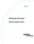
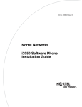
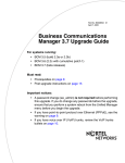
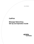
Part No. P1013654 01
March 24, 2004
BST Doorphone
Installation and Configuration
Guide
for Business Communication Manager systems with
version 3.6 software or higher
2
Copyright © 2004 Nortel Networks
All rights reserved. March 2004.
The information in this document is subject to change without notice. The statements, configurations, technical data, and
recommendations in this document are believed to be accurate and reliable, but are presented without express or implied
warranty. Users must take full responsibility for their applications of any products specified in this document. The
information in this document is proprietary to Nortel Networks NA Inc.
Trademarks
NORTEL NETWORKS is a trademark of Nortel Networks.
Microsoft, MS, MS-DOS, Windows, and Windows NT are registered trademarks of Microsoft Corporation.
All other trademarks and registered trademarks are the property of their respective owners.
P1013654 01
Contents
3
Contents
About the Business Series Terminal (BST) Doorphone . . . . . . . . . . . . . . . . 5
What you need to know . . . . . . . . . . . . . . . . . . . . . . . . . . . . . . . . . . . . . . . . . . . . . . . . . 5
Environment requirements . . . . . . . . . . . . . . . . . . . . . . . . . . . . . . . . . . . . . . . . . . . . . . . 5
How to get help . . . . . . . . . . . . . . . . . . . . . . . . . . . . . . . . . . . . . . . . . . . . . . . . . . . . . . . 6
DN configuration requirements for the BST Doorphone . . . . . . . . . . . . . . . 7
Creating a BST Doorphone DN record . . . . . . . . . . . . . . . . . . . . . . . . . . . . . . . . . . . . . 7
Other BST Doorphone configuration requirements . . . . . . . . . . . . . . . . . . . . . . . . . . . 12
Trunk/line data . . . . . . . . . . . . . . . . . . . . . . . . . . . . . . . . . . . . . . . . . . . . . . . . . . . . 12
Scheduled Services . . . . . . . . . . . . . . . . . . . . . . . . . . . . . . . . . . . . . . . . . . . . . . . 12
BST Doorphone Installation . . . . . . . . . . . . . . . . . . . . . . . . . . . . . . . . . . . . . 13
Wire and mount a BST Doorphone . . . . . . . . . . . . . . . . . . . . . . . . . . . . . . . . . . . . 13
Initialize a new BST Doorphone . . . . . . . . . . . . . . . . . . . . . . . . . . . . . . . . . . . . . . 15
Optional Equipment . . . . . . . . . . . . . . . . . . . . . . . . . . . . . . . . . . . . . . . . . . . . . . . . 15
Configuring BST Doorphone settings . . . . . . . . . . . . . . . . . . . . . . . . . . . . . 17
Testing the BST Doorphone . . . . . . . . . . . . . . . . . . . . . . . . . . . . . . . . . . . . . . . . . 19
Doorphone configuration tips . . . . . . . . . . . . . . . . . . . . . . . . . . . . . . . . . . . . . . . . 19
BST Doorphone Installation and Configuration Guide
4
Contents
P1013654 01
5
Chapter 1
About the Business Series Terminal (BST) Doorphone
This guide leads a Nortel Networks installer and/or system administrator through installing and
configuring a BST Doorphone on a Business Communications Manager system.
The BST Doorphone is used as an intercom device to control access to your building. It provides
call notification and handsfree communication from a site entry location to assigned telephones on
the Business Communications Manager system.
Note: Door opening capabilities are available with a Door Opening Controller (DOC).
For more information on DOC, refer to Optional Equipment on page 15.
This chapter contains:
• What you need to know
• Environment requirements
• How to get help
What you need to know
To install and configure a BST Doorphone you must:
• know how to log on to Unified Manager and use the Unified Manager interface.
Refer to the Business Communications Manager Programming Operations Guide for more
information.
• be a Nortel Networks installer with Business Communications Manager certification
• know basic Nortel Networks terminology
Environment requirements
Check the following environment requirements:
Temperature
-35° to 60°C (31° – 140°F)
Relative humidity
5% to 95% non-condensing
Background noise
up to 70 dB A
BST Doorphone Installation and Configuration Guide
6
Chapter 1 About the Business Series Terminal (BST) Doorphone
How to get help
USA and Canada
Authorized Distributors - ITAS Technical Support
Telephone:
1-800-4NORTEL (1-800-466-7835)
If you already have a PIN Code, you can enter Express Routing Code (ERC) 196#.
If you do not yet have a PIN Code, or for general questions and first line support, you can enter
ERC 338#.
Website:
http://www.nortelnetworks.com/support
Presales Support (CSAN)
Telephone:
1-800-4NORTEL (1-800-466-7835)
Use Express Routing Code (ERC) 1063#
EMEA (Europe, Middle East, Africa)
Technical Support - CTAS
Telephone:
* European Freephone
European Alternative/
United Kingdom
Africa
Israel
00800 800 89009
+44 (0)870-907-9009
+27-11-808-4000
800-945-9779
* Note: Calls are not free from all countries in Europe, Middle East or Africa
Fax:
44-191-555-7980
email:
[email protected]
CALA (Caribbean & Latin America)
Technical Support - CTAS
Telephone:
1-954-858-7777
email:
[email protected]
APAC (Asia Pacific)
Technical Support - CTAS
Telephone:
+61 388664627
Fax:
+61 388664644
email:
[email protected]
P1013654 01
7
Chapter 2
DN configuration requirements for the BST Doorphone
This chapter describes how to set up a DN record for a BST Doorphone prior to a hardware
installation.
Before installing a BST Doorphone, you must select and configure an Inactive DN (vacant port)
on the Business Communications Manager system for BST Doorphone compatibility.
Note: Some default DN settings can cause the BST Doorphone to automatically answer
incoming calls that are not intended to be heard over the BST Doorphone.
Creating a BST Doorphone DN record
Follow these steps to create a DN record for the BST Doorphone.
1
From Unified Manager, click on the keys beside Services, Telephony Services, System DNs,
and Inactive DNs.
Figure 1 Inactive screen example
2
Click on the key beside Set DNs.
Tips: The number of Inactive DNs for digital
telephones and peripherals on the Business
Communications Manager are shown under the Set
DNs heading.
3
Click on the Set DN record (DN XXX) that you want to configure for the BST Doorphone.
The figure below shows a detailed view of the information under the DN (DN xxx) headings.
DN headings and fields that must be reviewed for BST Doorphone compatibility are shown
with a red asterisk.
BST Doorphone Installation and Configuration Guide
8
Chapter 2 DN configuration requirements for the BST Doorphone
Figure 2 DNs headings
DN XXX
General
Name
Model
Device port
Control set
Call log passwords
Line Access
Prime line
Intercom keys
OLI number
Line Assignment
(Line 001)
Appearance type
Vmsg set
Line Pool Access
Pool A
Answer DNs
Capabilities
DND on busy
Handsfree
HF answerback
Pickup group
Page zone
Paging
**
**
* *
*
*
*
*
*
* *
*
4
*
*
*
Direct Dial
Priority call
Auto hold
Aux ringer
Allow redirect
Redirect ring
Keep DN alive
Receive short tones
SM Supervisor
Auto hold for incoming page
Call forward
Fwd no answer to
Fwd no answer delay
Fwd on busy to
Hotline
Type
ATA settings
Intrusion
User preferences
Model
Call log options
Dialing options
Language
Contrast
Distinctive Ring in Use
**
**
Button programming
User speed dial
External #
Facility
Restrictions
Set restrictions
Set lock
Allow last number
Allow saved number
Allow link
Schedules
Line/set restrictions
Telco features
First display
Auto called ID
Set log space
Available log space
Click General. The General heading allows you to assign the name to the BST Doorphone
and to view the physical port number assigned to the DN.
Figure 3 General screen example
*
*
P1013654 01
*
*
Chapter 2 DN configuration requirements for the BST Doorphone
5
9
Four general record values must be reviewed for BST Doorphone compatibility. These
settings are shown in the following table. Use this table to change general record values (if
required) for the BST Doorphone.
Table 1 General record values
Attribute
Value
Description
Name
<up to seven alphanumeric
characters>
Use this field to provide a more specific description of the BST
Doorphone, such as BackDR for Back Door.
Model
M7324
This heading appears for telephones and peripherals in the digital
DN range, which starts at the start DN (default:221) up to DN 433.
Choose M7324 for the BST Doorphone.
Device port
<port number>
This read-only field shows the port number for the Set DN.
Remember this port number when you are installing the BST
Doorphone to a station module on the Business Communications
Manager system.
Control set
None
Set this value to None for the BST Doorphone.
Note: For a detailed explanation on all general record values, refer to the Business
Communications Manager Programming Operations Guide.
6
Click on the Line access heading.
Figure 4 Line access screen example
*
*
Two line access fields must be reviewed for BST Doorphone compatibility. These setting are
shown in the following table. Use this table to change line access fields (if required) for the
BST Doorphone.
Table 2 Line access fields
Attribute
Values
Description
Prime line
I/C
Ensure that the prime line value is set to I/C for the BST Doorphone.
Intercom (I/C)
keys
1
Assign only one intercom key to the BST Doorphone.
Note: For a detailed explanation on all line access fields, refer to the Business Communications
Manager Programming Operations Guide.
BST Doorphone Installation and Configuration Guide
10
Chapter 2 DN configuration requirements for the BST Doorphone
7
Click on the Line assignment heading and remove line assignment for this DN.
8
Click on the Line pool access heading and remove line pool access for this DN.
9
Click on the Answer DNs heading and remove Answer DNs assignments for this DN.
Figure 5 Line assignment, Line pool access and Answer DNs screen example
Note: Refer to the Business Communications Manager Programming Operations Guide for
more information on how to remove lines, line pools and Answer DNs assignments on a DN
record.
10 Click on the Capabilities heading.
Figure 6 Capabilities screen example
*
*
*
*
*
P1013654 01
Chapter 2 DN configuration requirements for the BST Doorphone
11
Five capabilities fields must be reviewed for BST Doorphone compatibility. These capabilities
fields are shown in the following table. Use this table to change capabilities fields (if required)
for the BST Doorphone.
Table 3 Capabilities fields
Attribute
Values
Description
DND on busy
N or Y
Set this value to N (No) for the BST Doorphone.
Handsfree
Auto
Standard
None
Set this value to Auto for the BST Doorphone.
Paging
N or Y
Set this value to Y (Yes) for the BST Doorphone.
Direct dial
None
Set this value to None for the BST Doorphone.
Aux ringer
N or Y
Set this value to N (No) for the BST Doorphone.
Note: For a detailed explanation on all capabilities fields, refer to the Business
Communications Manager Programming Operations Guide.
11 Click on the key beside Capabilities, then Click on Call forward.
Ensure that the two call forward fields (Fwd no answer to and Fwd on busy to) are blank
Figure 7 Call Forward screen example
12 Click on Hotline.
Ensure that the Hotline type is set to None.
Figure 8 Hotline screen example
13 Repeat the above steps for every BST Doorphone you plan to install on the system.
BST Doorphone Installation and Configuration Guide
12
Chapter 2 DN configuration requirements for the BST Doorphone
Other BST Doorphone configuration requirements
Trunk/line data
Ensure that the BST Doorphone DN (DN XXX) is not assigned as a prime set for lines on the
Business Communications Manager system.
The Unified Manager displays all active lines under:
Services, Telephony Services, Lines and All lines headings.
Figure 9 Trunk/line data screen examples
Note: For more information on trunk/line assignments, refer
to the Business Communications Manager Programming
Operations Guide.
Scheduled Services
Ensure that the BST Doorphone DN (DN XXX) is not assigned as a control set, extra dial set or a
ringing set for scheduled services.
The Unified Manager displays three services (ringing, restrictions and routing) under:
Services, Telephony Services, Scheduled services headings.
Figure 10 Scheduled services screen examples
Note: For more information on scheduled services, refer to
the Business Communications Manager Programming
Operations Guide.
P1013654 01
13
Chapter 3
BST Doorphone Installation
This chapter describes how to install a BST Doorphone and connect it to a reserved station module
port on the Business Communications Manager system.
The BST Doorphone can be mounted in a standard recessed double-gang electrical box for flush
mounting or surface mounted using the optional surface mount bracket. Mount the BST
Doorphone at shoulder height (approximately 5 ft.) in the absence of other specifications, such as
compliance with local handicapped access regulations, if required.
Select a location for the BST Doorphone within 300 m (1000 ft.) of the Business Communications
Manager system. This distance can be increased to 780 m (2600 ft.) with the connection of a
Station Auxiliary Power Supply (SAPS) to a BST Doorphone.
The BST Doorphone is suitable for exposure to weather; however, care must be taken to ensure
holes or recesses provided for the BST Doorphone are properly sealed to prevent water from
entering the wall in exposed locations. Gaskets are supplied for both flush and wall mount
installations. No gasket is required between the BST Doorphone and surface mount bracket.
Caution: You must install protection devices when wiring between the BST Doorphone
and the Business Communications Manager system is routed outside a building, such as
aerial or buried cable. Protection devices must be installed at each end of the exposed
cable. Nortel Networks recommends the ITW LINX MP1A-90-27 secondary protector for
this purpose.
Wire and mount a BST Doorphone
1
Remove the BST Doorphone’s faceplate.
2
Determine if you want a flush or surface mount installation.
For a surface mount:
Figure 11 Surface mount
•
Discard the flush mount gasket.
•
Verify the correct orientation of the
surface mount gasket.
•
Thread the wires through the center hole,
then through the surface mount bracket.
•
Fasten the surface mount bracket at the
desired location on the wall.
Surface mount gasket
Surface mount
bracket
Main housing
assembly
Faceplate
BST Doorphone Installation and Configuration Guide
14
Chapter 3 BST Doorphone Installation
OR
For a flush mount:
(into an electrical box embedded in the wall)
•
Discard the surface mount gasket and
bracket.
•
Slide the flush mount gasket onto the main
housing assembly.
Figure 12 Flush mount
Wall
Main housing
assembly
Flush mount
gasket
3
Run a standard 3-pair cable from the Business
Communications Manager system to the BST
Doorphone location.
Use one pair to connect the ''KSU'' terminals
of the BST Doorphone to a reserved station
module port on the Business
Communications Manager system.
Strip wires 6 mm (1/4 inch) before inserting
them in the terminal block and tightening.
The second pair can be used to connect an
optional DOC, leaving a spare pair for a
SAPS installation. For more information on
DOC, refer to Optional Equipment on page 15.
4
Faceplate
Figure 13 BST Doorphone TCM connector
screw block
KSU
SAPS
DOC
Note: BST Doorphone connections
are polarity insensitive.
Fasten the BST Doorphone’s faceplate to the main housing assembly.
Note: When the surface mount bracket is used, secure the wiring with a cable tie through the
round holes in the rear of the surface mount bracket or electrical box (customer supplied),
before fastening the BST Doorphone’s faceplate to the main housing assembly.
P1013654 01
Chapter 3 BST Doorphone Installation
15
Initialize a new BST Doorphone
To get the system to recognize a new BST Doorphone installation, you need to perform one of the
following:
• In the Unified Manager, click on System. Go to the top menu and click on View, then select
Refresh. The Unified Manager refreshes and the allows BST Doorphones to be recognized by
the system.
OR
• In the Unified Manager, click on System. Go to the top menu and click on Logoff, then select
Reboot. The system reboots and brings BST Doorphones on line.
Note: If you do a reboot, telephony services are temporarily unavailable
The BST Doorphone will identify itself to the system as a M7324 telephone.
Note: The Call button’s backlight automatically turns on when the
BST Doorphone is connected to a station module port on the
system. The backlight is useful in low light conditions.
✙
✙
Call button
Optional Equipment
The Door Opening Controller (DOC) operates through a BST Doorphone to provide door opening
control. The DOC receives data from the BST Doorphone, that is compared against a dip-switch
set code for activation.
The DOC provides convenient control of locked mechanisms but is not intended for sole building
entry security. In high security environments, backup systems should be used for added protection.
Power failure, device failure, wiring faults and unauthorized equipment access can all contribute to
a failed locked or unlocked situation.
For more information on the DOC, refer to documentation provided with the DOC unit.
BST Doorphone Installation and Configuration Guide
16
Chapter 3 BST Doorphone Installation
P1013654 01
Chapter 4 Configuring BST Doorphone settings
17
Chapter 4
Configuring BST Doorphone settings
This chapter describes the screen that you use to configure BST Doorphone settings once you have
performed the initial DN configuration and installed the unit.
Doorphone programming allows you to customize feature settings for individual BST Doorphones
on the Business Communications Manager system.
Follow these steps to configure Doorphone settings:
1
From Unified Manager, click on the keys beside Services, Doorphones, Doorphone List.
Tips: The number of BST Doorphones installed on the
Business Communications Manager are shown under the
Doorphone List heading.
A maximum of 250 BST Doorphones can be attached to the
Business Communications Manager system.
2
Click on the Doorphone you want to program (for example, Doorphone 1).
Figure 14 Doorphone settings
BST Doorphone Installation and Configuration Guide
18
Chapter 4 Configuring BST Doorphone settings
3
Use the information in the following table to change the Doorphone settings.
Table 4 BST Doorphone settings
Setting
Values
Description
Doorphone state
Active
Inactive
This read-only field indicates if the Doorphone is detected on
the system and is operational.
Doorphone DN
<DN>
This read-only field shows the DN assigned to this Doorphone.
Speaker volume
Low
Medium
High
Assign a volume level for the Doorphone speaker.
Chime volume
Low
Medium
High
Assign a volume level for chime tones played during a
Doorphone page.
Call Action
Ring Set
Page
Both
Select a call activity when the Doorphone Call button is
pressed.
Ring Set: Calls an internal telephone.
Page: Sends a page tone to a specific group of telephones in a
page zone.
Both: Calls an internal telephone. If the call is not answered
after a set length of time, a page tone is sent to a specific
group of telephones in a page zone.
Target DN
< any telephone DN>
Enter the DN number of the internal telephone to call when the
Doorphone’s Call button is pressed.
Ring Delay
1 to 60 seconds
Select a set length of time (in seconds) to allow ringing at the
Target DN before the call is automatically disconnected.
Page Target
Internal
External
Both
Internal: Make a page announcement to a specific group of
telephones in a page zone, through the telephone speakers.
External: Make a page announcement through an external
loudspeaker system.
Both: Make a page announcement through telephone
speakers and an external loudspeaker system.
Page Zone
Zone (1 to 6)
All
Assign Doorphone paging to one of six page zones.
Select All to assign Doorphone paging to all six page zones.
Chime Sequence
1 to 4
None
Custom
During a Doorphone page, a page tone will be heard followed
by the distinctive chime.
Select one of four standard distinctive chimes.
Select None to have no chimes presented during a Doorphone
page (only a page tone will be heard)
Select Custom for an unique chime setting. You must enter a
custom chime sequence in the Custom Chime setting.
Custom Chime
< 0 to 8 digit string>
Allows you to create your own chime tune using the following
parameters:
0 to 4 - chime tone (pitch) increases by number
5 = silence
Opener Type
DOC
None
Allows you to specify if a Door Opening Controller (DOC) is
connected to the Doorphone.
P1013654 01
Chapter 4 Configuring BST Doorphone settings
19
Table 4 BST Doorphone settings (Continued)
Setting
Values
Description
Open Digit
0 - 9, * or #
None
< one-digit code>
The Open digit setting allows you to specify a single digit code
to unlock a door or gate when a DOC is connected to the
Doorphone.
Select None to disable this setting.
Note:
The Open digit setting must match the dip-switch set code on the DOC. For more
information on DOC, refer to Optional Equipment on page 15.
Hardware ID
4
<10 character string>
This read-only field that shows the hardware identification
number assigned to the Doorphone.
Repeat the above steps for each BST Doorphone installed on the system.
Testing the BST Doorphone
You can perform the following tasks to test the Doorphone settings:
• Press the Call button on the BST Doorphone and ensure the Target DN telephone rings.
• Let the Target DN telephone ring until the call is automatically disconnected. Ensure that a page
tone followed by the Doorphone’s distinctive chime is heard at specified telephones included in
the Doorphone’s page zone.
• To establish a voice path, dial the BST Doorphone’s DN from any telephone on the system, or
press the Call button on the BST Doorphone and answer the ringing call at the Target DN
telephone.
• If installed, test the DOC as shown below:
— Press the Call button on the BST Doorphone and answer the call at the Target DN
telephone.
— To open the door, dial the single digit code (specified in Doorphone programming) or on a
two-line display telephone, press the OPEN display button.
— Press the release button or hang up to end the test.
Doorphone configuration tips
• The Doorphone’s Target DN telephone should be assigned to the same page zone that is used by
the Doorphone for paging (chime presentation).
• The Doorphone can ring several telephones on the system using Answer DNs. Program one or
more telephones to have a Ringing Answer button for the Target DN telephone.
— For example, the Target DN telephone is DN 230. Assign DN 230 as an Answer DN for
extensions 223, 224 and 225. When the BST Doorphone Call button is pressed, four
telephones on the system will ring (telephones: 230, 222, 223 and 225).
For more information on Answer DNs and assigning telephones to page zones, refer to the
Business Communications Manager Programming Operations Guide.
BST Doorphone Installation and Configuration Guide
20
Chapter 4 Configuring BST Doorphone settings
P1013654 01