1
Part No. P0989728 02
Business Communications
Manager
Digital Drop & Insert (DDI) MUX
Installation Guide
2
Copyright © 2002 Nortel Networks
All rights reserved. April 26, 2002.
The information in this document is subject to change without notice. The statements, configurations, technical data, and
recommendations in this document are believed to be accurate and reliable, but are presented without express or implied
warranty. Users must take full responsibility for their applications of any products specified in this document. The
information in this document is proprietary to Nortel Networks NA Inc.
Trademarks
NORTEL NETWORKS and Business Communications Manager, are trademarks of Nortel Networks NA Inc.
Microsoft, MS, MS-DOS, Windows, and Windows NT are registered trademarks of Microsoft Corporation.
Symbol, Spectrum24, and NetVision are registered trademarks of Symbol Technologies, Inc.
All other trademarks and registered trademarks are the property of their respective owners.
P0989728 02
3
Contents
Preface
9
Symbols used in this guide
9
Text conventions
10
Acronyms
10
Related publications
11
How to get help
11
Installing the DDI MUX
13
Before you start
14
Business Communications Manager system requirements
14
Setting the DIP switches
15
Determining the module DIP switch settings
15
Setting the DIP switches on the DDI MUX
16
Installing the DDI MUX in the Business Communications Manager system
18
Important safety instructions
18
Installation overview
18
Shutting down the system
19
Installing DDI MUX
20
Starting up the system
21
Connecting the DDI MUX
22
DTE cables
Configuring the DDI MUX
23
25
Assigning the DDI MUX modules
25
Assigning lines for voice traffic
25
Assigning lines to the data module
26
Removing a line assignment
Configuring the DDI MUX to work with the DTE
Testing the DDI MUX
28
28
29
DTE Loopback test
30
DS30 Loopback test
31
Troubleshooting
32
LED Indicator and Diagnostics
32
Installation troubleshooting
34
Problems with equipment
Programming Record
34
36
DDI MUX Installation Guide
4
P0989728 02
5
Figures
Figure 1
Overview of network using DDI MUX with the
Business Communications Manager internal router
13
Overview of network using DDI MUX with an external router
14
Figure 3
Switches on the DDI MUX
16
Figure 4
Removing the front bezel
20
Figure 5
Identifying the media bay module latches
20
Figure 6
DDI MUX connections
22
Figure 7
DTE Loopback Test
30
Figure 8
DDI MUX LEDs
32
Figure 2
DDI MUX Installation Guide
6
P0989728 02
7
Tables
Table 1
DDI MUX switch settings
15
Table 2
V.35 cables
23
Table 3
List of the signals and pinouts specified by V.35
24
Table 4
List of all the multiples of 56000 and 64000 bits/s
27
Table 5
DDI MUX Configuration settings
29
Table 6
DDI MUX LEDs
33
DDI MUX Installation Guide
8
P0989728 02
9
Preface
This guide describes how to install and initialize the Digital Drop & Insert (DDI) MUX media bay
module.
Information in this explains how to:
•
•
install the DDI MUX
initialize the DDI MUX
To use this guide, you must:
•
•
be a Nortel Networks installer with Business Communications Manager accreditation
know basic Nortel Networks terminology
Symbols used in this guide
This guide uses symbols to draw your attention to important information. The following symbols
appear in this guide:
Caution: Caution Symbol
Alerts you to conditions where you can damage the equipment.
Danger: Electrical Shock Hazard Symbol
Alerts you to conditions where you can get an electrical shock.
Warning: Warning Symbol
Alerts you to conditions where you can cause the system to work improperly or to fail.
Note: Note Symbol
Alerts you to important information.
Tip: Tip Symbol
Alerts you to additional information that can help you perform a task.
Warning: Grounding Symbol.
Alerts you to ground yourself with an antistatic grounding strap before performing the
maintenance procedure.
DDI MUX Installation Guide
10
Preface
Warning: Disconnect Symbol
Alerts you to remove the Business Communications Manager base unit and Business
Communications Manager expansion unit power cords from the AC outlet before
performing any maintenance procedure.
Text conventions
This guide uses the following text conventions:
bold Courier text
Indicates command names and options and text that you need to enter in
a command-line interface.
Example: Use the dinfo command.
Example: Enter show ip {alerts|routes}.
italic text
Indicates file and directory names, new terms, book titles, Web
addresses, and variables in command syntax descriptions.
bold text
Indicates command names, screen titles, options and text for a graphical
user interface (GUI).
angle brackets (< >)
Indicates a keyboard key press or simultaneous key presses, i.e.
<ENTER> or <CTRL j>
or when part of a command string, indicates that a variable is to be
entered.
Example: <IP address>, where the information to be entered at that
point is the specific information for the required field, in this case, a
specific IP address.
Acronyms
These are the acronyms used in this document.
BPS
Bits per second
CSU
Channel service unit
DSU
Data service unit
DTM
Digital Trunk media bay module
LAN
Local area network
MSC
Media services card
MUX
Multiplexor
WAN
Wide area network
P0989728 02
Preface
11
Related publications
The following documents provide further information about the Business Communications
Manager base unit and related media bay modules, extension equipment, and the applications and
software on the system:
•
•
Business Communications Manager 2.5 Programming and Operations Guide describes how to
program the Business Communications Manager equipment.
The Business Communications Manager 2.5 Installation and Maintenance Guide describes
how to install and maintain a Business Communications Manager system.
How to get help
•
USA and Canada
Authorized Distributors - ITAS Technical Support
Telephone: 1-800-4NORTEL (1-800-466-7835)
If you already have a PIN Code, you can enter Express Routing Code (ERC) 196#
If you do not yet have a PIN Code, or for general questions and first line support, enter ERC
338#
Website: http://www.nortelnetworks.com/itas/
email: [email protected]
Presales Support (CSAN)
Telephone: 1-800-4NORTEL (1-800-466-7835)
Use Express Routing Code (ERC) 1063#
•
EMEA (Europe, Middle East, Africa)
Technical Support - CTAS
Telephone: 00800 800 89009 or 33 4 9296 1341
Fax: 33 49296 1598
email: [email protected]
•
CALA (Caribbean & Latin America)
Technical Support - CTAS
Telephone: 1-954-858-7777
email: [email protected]
•
APAC (Asia Pacific)
Technical Support - CTAS
Telephone: +61 388664627
Fax: +61 388664644
email: [email protected]
DDI MUX Installation Guide
12
Preface
P0989728 02
Installing the DDI MUX
13
Installing the DDI MUX
The Business Communications Manager Digital Drop & Insert (DDI) MUX enables a Business
Communications Manager system to share its connection to a Universal T1 network with a local
area network (LAN). A DDI MUX allows you to make more efficient use of your digital network
resources and reduces the amount of equipment needed to support your voice and data networks.
The DDI MUX:
•
•
•
•
•
•
provides the functionality of a DTM media bay module (T1 digital lines only)
splits the incoming T1 line so that some of the lines are used for voice traffic and some of the
lines are used for data traffic
provides either the CSU (Channel Service Unit) or DSU (Data Service Unit) functionality to
support connections to data terminal equipment (DTE), such as a router or a bridge
connects to network devices that support V.35 interfaces
provides end-to-end transparent bit service
supports loopbacks between the DDI MUX and the internal Business Communications
Manager components, and between the DDI MUX and digital terminal equipment
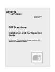
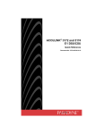
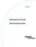
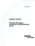
Figure 1 Overview of network using DDI MUX with the Business Communications Manager internal
router
Switch/Hub
T1 mux service
Service Provider/
PSTN
DTE cable
DDI MUX Installation Guide
14
Installing the DDI MUX
Figure 2 Overview of network using DDI MUX with an external router
Switch/Hub
Router
T1 mux service
DTE cable
Service Provider/
PSTN
Before you start
•
•
Make sure you read and follow the instructions in this guide.
Make sure you have the correct cable to connect to your DTE.
The DTE cable is ordered separately so you can select the correct cable for your application.
For more information about the DTE cables available, refer to “DTE cables” on page 23.
Business Communications Manager system requirements
•
•
•
Make sure your Business Communications Manager system is using Business
Communications Manager 2.5 Feature Pack 1 software or higher.
Make sure you have an available media bay on the Business Communications Manager Base
Unit.
Make sure you have two DS30 channels available.
P0989728 02
Installing the DDI MUX
15
Setting the DIP switches
Before you install the DDI MUX, you must set the DIP switches located on the back of the media
bay module. These DIP switches determine the DS30 channels assigned to the DDI MUX.
To set the DIP switches, you need to:
•
•
determine the module switch setting you want to use
set the DIP switches
Determining the module DIP switch settings
The DDI MUX module combines a DTM (Digital Trunk Module) and a Data Module. The switch
setting you choose determines the DS30 channel assigned to the DTM portion of the DDI MUX.
The Data Module is automatically assigned the next DS30 channel number.
The DS30 channel you assign to the DDI MUX determines the line numbers of the T1 line
connected to the DDI MUX. Table 1 shows the switch settings for each DS30 channel, and the
resulting line assignments.
Table 1 DDI MUX switch settings
DDI MUX DS30
channel
2
3
4
5
6
7
Enter these switch settings
1
2
3
4
5
6
on
on
on
on
on
on
on
on
on
on
on
off
on
on
on
on
on
off
on
on
on
on
on
on
on
off
off
off
on
on
Assigns these
lines numbers
Data Module
DS30 channel
211-234
3
181-204
4
151-174
5
121-144
6
91-114
7*
**
* If your system is configured with a 3/5 DS30 channel split, you cannot use DS30 channel 6 for the DDI
MUX. When you use a 3/5 split, DS30 channel 7 is not available for the data module portion of the DDI
MUX.
** You cannot use DS30 channel 7 for the DDI MUX. If you assign DS30 channel 7, there is no DS30
channel available for the data module portion of the DDI MUX.
DDI MUX Installation Guide
16
Installing the DDI MUX
To determine the DIP switch settings for the DDI MUX:
1
Use Table 1 to determine the DS30 channel that assigns the line numbers you want to use with
the DDI MUX.
Warning: Do not use DS30 channel 7 for the DDI MUX module. If you choose DS30
channel 7, there is no DS30 channel available for the data module.
If your Business Communications Manager system is set to a 3/5 DS30 channel split,
do not use DS30 channel 6 or 7.
2
Use Table 1 to determine the DIP switch settings you want to use for the DDI MUX.
The DS30 channel you choose for the DDI MUX, and next DS30 channel, can not be used by any
other media bay module installed in the Business Communications Manager system. For detailed
information about choosing the DS30 channels for all of the media bay modules, refer to the
Business Communications Manager Installation and Maintenance Guide.
Setting the DIP switches on the DDI MUX
After you have determined the DIP switch settings for the DDI MUX, you need to set the DIP
switches.
Follow these steps to set the DIP switches:
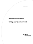
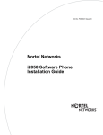
1
Locate the DIP switches on the DDI MUX.
Figure 3 Switches on the DDI MUX
On
1 2 3 4 5 6
Off
DIP switches
Back of the DDI MUX
P0989728 02
Module is
right-side up
Installing the DDI MUX
2
17
Set the switches to correspond with the settings you chose in “Determining the module DIP
switch settings” on page 15.
You are now ready to install the modules into the Business Communications Manager system.
Tip: Create a label with the DS30 channel and DIP switch settings, and stick it to the front
of the module to provide ease of reference for maintenance activities.
DDI MUX Installation Guide
18
Installing the DDI MUX
Installing the DDI MUX in the Business Communications
Manager system
Important safety instructions
The following safety instructions cover the installation and use of the DDI MUX. Read carefully
and retain for the future.
Warning: To avoid electrical shock hazard to personnel or equipment damage,
observe the following precautions when installing telephone equipment.
1
Never install telephone wiring during a lightning storm.
2
Never install telephone jacks in wet locations unless the jack is specifically designed for wet
locations.
3
Never touch uninsulated telephone wires or terminals unless the telephone line has been
disconnected at the network interface.
4
Use caution when installing or modifying telephone lines. The exclamation point within an
equilateral triangle is intended to alert the user to the presence of important operating and
maintenance (servicing) instructions in the literature accompanying the DDI MUX.
Installation overview
After you set the switches on the DDI MUX, you can install it in the Business Communications
Manager base unit.
Note: The DDI MUX and DTM media bay modules must be installed in the Business
Communications Manager base unit. If there is no room in the base unit, move one of the
other types of media bay module to the Business Communications Manager expansion
unit to provide space.
To install the DDI MUX, you need to:
•
•
•
shut down the Business Communications Manager
install the DDI MUX
start up the Business Communications Manager
Danger: The Business Communications Manager must be correctly powered down
before you install or remove media bay modules.
P0989728 02
Installing the DDI MUX
19
Shutting down the system
Before you shut down the system, read the following warnings to ensure you and your system are
properly protected.
Warning: If you are installing a new system, or new base unit or expansion unit, refer
to the “Installing telephones and peripherals” section of the Business Communications
Manager Installation and Maintenance Guide for instructions about installing a new
system before you connect the system to the ac power outlet.
Warning: DO NOT continue with module installation until you ensure the base unit
and expansion unit are set to the correct voltages (version 2.0 systems with standard
power supply).
Warning: Failure to follow procedures to properly disconnect the Business
Communications Manager base unit and expansion unit, can result in module or system
damage.
Warning: Ensure you are properly grounded before handling modules or any
components that are part of the Business Communications Manager hardware.
This section describes the recommended procedure for shutting down the Business
Communications Manager prior to installing new modules.
1
If you are adding or replacing a module in an active system, start a Unified Manager session
with the Business Communications Manager and follow these steps first:
a
Choose System.
b
Click the Logoff menu and then click Shutdown.
c
Click the Yes button.
d
Wait until the Status changes to Complete! It is safe to turn off the system.
e
Click the Done button.
f
Exit Unified Manager.
Note: For information about how to use Unified Manager, refer to the Business
Communications Manager Programming Operations Guide.
2
Attach one end of the grounding strap to your wrist and the other end to a grounded metal
surface.
3
Ensure the cables connected to the front of the base unit and the expansion unit are clearly
marked.
DDI MUX Installation Guide
20
Installing the DDI MUX
4
Unplug any telephone or network cables from all the media bay modules and the MSC on the
Business Communications Manager base unit and the expansion unit.
5
Disconnect the base unit and expansion unit power cords from the ac outlet.
Installing DDI MUX
After the system is powered down, you can install the DDI MUX. Follow this procedure to install
the DDI MUX.
1
Remove the front bezel from the base unit. To remove the bezel, grasp the edges and pull the
bezel forward. Refer to Figure 4.
Figure 4 Removing the front bezel
Grasp the edge of the front bezel and pull
it forward
Business Communications Manager base unit
2
Select an open media bay.
Note: If there is no open media bay, select a media bay module to move to the
Business Communications Manager expansion unit. Do not move a DTM to the
expansion unit.
3
Pull the latch beside the selected bay to release the media bay bezel. Refer to Figure 5.
Figure 5 Identifying the media bay module latches
media bay module latches
Business Communications Manager base unit
P0989728 02
Installing the DDI MUX
21
4
With the face of the module towards yourself, insert the media bay module into the open bay,
ensuring that the sides of the module are parallel with the sides of the bay.
5
Gently push the media bay module straight back into the unit.
Warning: Insert the DDI MUX carefully and squarely into the housing to ensure that the
power connector on the module correctly and securely connects to the backplane of the
media bay.
You will hear a click when the module is firmly seated in the media bay. The module sits
slightly forward from the face of the Business Communications Manager. When the front
bezel is replaced, the module face is flush with the surface of the unit.
6
Replace the front bezel on the base unit.
Starting up the system
After you install the module correctly into the bay, you must return the equipment to operation in
an orderly way.
Follow these steps carefully to ensure that you return your system to operation without
endangering the equipment or yourself.
1
Plug the power cords for the Business Communications Manager base unit and the expansion
unit back into the ac outlets.
Note: The Business Communications Manager system starts up when you connect the ac
power cord. System startup takes several minutes to complete.
2
Connect the telephone and network cables to the proper outlets on the media bay modules and
the MSC.
3
Check that the LEDs on the modules are on and static. Refer to “Installation troubleshooting”
on page 34 for a detailed description of the LED states.
DDI MUX Installation Guide
22
Installing the DDI MUX
Connecting the DDI MUX
After you have installed the DDI MUX, you can begin connecting it.
To connect the DDI MUX:
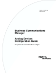
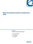
1
Connect the T1 cable to the RJ48C socket on the DDI MUX.
2
Wire the other end of the T1 cable to the telco demarcation blocks of the building.
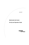
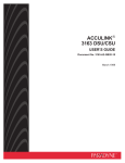
Figure 6 shows the wiring pinouts for a DDI MUX to connect to a service provider.
Figure 6 DDI MUX connections
Data port (DTE cable)
10101
TxD
RxD
RTS
CTS
DCD
DSR
To network
To plug
Receive from
network
1- Rring
2 - Rtip
3 - Rshield
Transmit to
network
4-Tring
5-Ttip
6-Tshield
TM
RJ48C jack
12345678
3
Connect one end of the DTE cable to the Data Port on the DDI MUX.
4
Connect the other end of the DTE cable to the Business Communications Manager WAN card
or an external DTE.
Note: The DDI MUX supports DTE cables up to 15m (50 feet) long. A cable longer
than 15m (50 feet) can be used but may not be reliable.
P0989728 02
Installing the DDI MUX
23
DTE cables
The DTE cable connects the DDI MUX to the DTE (an external router or the Business
Communications Manager WAN card). The type of cable you use depends on the DTE and
protocol you are using.
This section describes the pin outs of the cables available for the DDI MUX to support the
following standard interfaces:
•
V.35
Contact your Nortel Networks Distributor to order specific router cables.
V.35 cables
There are four V.35 cables available from Nortel Networks. These cables are ordered separately so
you can select the correct cable for you application.
Table 2 V.35 cables
Cable description
NT code
CPC code
Data Interface Cable v.35, M34 Female, DDIM to external router with Winchester
NTAB2936
connector
A0781475
Data Interface Cable v.35, DB-44 Male, DDIM to external router
NTAB2940
A0781479
Data Interface Cable v.35, LFH DB-60, DDIM to external router
NTAB2941
A0781480
Data Interface Cable v.35, DB-26 Male, DDIM to BCM WAN interface (internal
router)
NTAB9802
A0888656
DDI MUX Installation Guide
24
Installing the DDI MUX
V.35 interface
The following table describes the pin outs of the data port on the DDI MUX. This port supports the
standard V.35 interface.
Table 3 List of the signals and pinouts specified by V.35
DDI MUX Port
V.35 Interface
Shield GND
1
A
Frame Ground
DTE Signal GND (102a)
7
B
Signal Ground
DCE Signal GND (102b)
23
B
Signal Ground
TxD+ (103)
2
P
Transmit Data A
TxD- (103)
14
S
Transmit Data B
RxD+ (104)
3
R
Receive Data A
RxD- (104)
16
T
Receive Data B
RTS+ (105)
4
C
Request To Send
RTS- (105)
19
NA
No Connect
CTS+ (106)
5
D
Ready for sending
CTS- (106)
13
NA
No Connect
DSR+ (107)
6
E
Data Set Ready
DSR- (107)
22
NA
No Connect
DTR+ (108)
20
H
Data Terminal Ready
DTR- (108)
26
NA
No Connect
DCD+ (109)
8
F
Data Channel Received Line Signal Detector
DCD- (109)
10
NA
No Connect
TxClk+ (113)
24
U
DTE Transmitter Signal Element Timing A
TxClk- (113)
11
W
DTE Transmitter Signal Element Timing B
TxSync+ (114)
15
Y
DCE Transmitter Signal Element Timing A
TxSync- (114)
12
AA
DCE Transmitter Signal Element Timing B
RxClk+ (115)
17
V
DCE Receiver Signal Element Timing A
RxClk- (115)
9
X
DCE Receiver Signal Element Timing B
RLPBK (140)
21
N
LLPBK (141)
18
L, K
Local Loopback
TM (142)
25
NN
Test Indicator
Loopback/Maintenance test
1
1 The K pin is connected with LLPBK for compatibility with Cisco equipment.
P0989728 02
Installing the DDI MUX
25
Configuring the DDI MUX
After you have installed the DDI MUX, you need to configure the DDI MUX settings. You can
change these settings using Unified Manager. For general instructions on how to use Unified
Manager, refer to the Business Communications Manager Programming Operations Guide.
To configure the DDI MUX, you need to:
•
•
•
•
assign the DDI MUX modules
assign the lines for voice traffic
assign lines to the Data Module of the DDI MUX
configure the DDI MUX to work with the DTE
Before you start, make sure you record the settings for the DDI MUX in the Programming Record
at the back of this guide.
Assigning the DDI MUX modules
1
Start a Unified Manager session.
For information about how to start and use Unified Manager, refer to the Business
Communications Manager Programming Operations Guide.
2
Click the Resources key and then the Media Bay Modules key.
3
Click the heading of the Bus number you assigned to the DDI MUX.
The Bus number is the same as the DS30 channel number you assigned to the DDI MUX using
the DIP switches on the module.
4
Make sure the option in the Programmed Bus Type drop list is Trunk module.
5
Click the heading of the next Bus number.
This Bus number is the DS30 channel automatically assigned to the Data Module portion of
the DDI MUX.
6
Click the Programmed Bus Type drop list and then click Data module.
Assigning lines for voice traffic
A digital T1 line has up to 24 telephone lines available for use. With the DDI MUX, you can
assign some of these lines to telephony traffic and some to data traffic.
For the lines that you want to use for telephony traffic, configure the lines in the same manner as
you configure lines for a DTM. For information about how to configure digital lines on a DTM,
refer to the Business Communications Manager Programming Operations Guide.
DDI MUX Installation Guide
26
Installing the DDI MUX
Assigning lines to the data module
The number of lines you assign to the data module determines the bandwidth of your data
networking connection. Table 4 shows the allocated bandwidth for the DDI MUX according to the
number of lines assigned. The allocated bandwidth also depends on the line data rate indicated by
the B channel data rate parameter.
To assign a line to the data module, you must change the line type to Fixed Data Channel and then
assign the line to the data module. To assign a line to the data module:
1
Start a Unified Manager session.
For information about how to start and use Unified Manager, refer to the Business
Communications Manager Programming Operations Guide.
2
Click the Services key and then the Telephony Services key.
3
Click the Lines key and then click the Physical lines key.
4
Click the All physical lines key.
5
Click the key of one of the line numbers you want to assign to the Data Module.
Note: All lines assigned to the DDI MUX must be on the T1 interface connected to
the DDI MUX.
6
Click the Trunk/line data heading.
7
Click the Trunk type drop list and then click Fixed data channel.
8
Repeat steps 5 to 7 for each line you want to assign to the Data Module.
9
Click the Resources key and then the Media Bay Modules key.
10 Click the key of the Bus number assigned to the Data Module.
11 Click the Data module key and then the Fixed line assignment heading.
12 Click the Add button.
The Add Fixed line assignment dialog box appears.
13 In the Line box, enter the line number of one of the lines you want to assign to the Data
Module.
Note: You can assign up to 24 lines to the DDI MUX.
You cannot assign any lines to the DDI MUX except Fixed lines.
14 Click the Save button.
15 Repeat steps 12 to 14 for each line you want to assign to the Data Module.
P0989728 02
Installing the DDI MUX
27
Table 4 List of all the multiples of 56000 and 64000 bits/s
Number of
lines selected
56000 bits/s
64000 bits/s
1
56000
64000
2
112000
128000
3
168000
192000
4
224000
256000
5
280000
320000
6
336000
384000
7
392000
448000
8
448000
512000
9
504000
576000
10
560000
640000
11
616000
704000
12
672000
768000
13
728000
832000
14
784000
896000
15
840000
960000
16
896000
1024000
17
952000
1088000
18
1008000
1152000
19
1064000
1216000
20
1120000
1280000
21
1176000
1344000
22
1232000
1408000
23
1288000
1472000
24
1344000
1536000
DDI MUX Installation Guide
28
Installing the DDI MUX
Removing a line assignment
If you decide you want to remove a line assignment from the Data Module and use it as a
telephony line, use the procedure below:
1
Start a Unified Manager session.
For information about how to start and use Unified Manager, refer to the Business
Communications Manager Programming Operations Guide.
2
Click the Resources key and then the Media Bay Modules key.
3
Click the key of the Bus number assigned to the Data Module.
4
Click the Data module key and then click the Fixed line assignment heading.
5
Click on the line number you want to remove.
6
Click the Delete button.
A confirmation dialog box appears.
7
Click the Yes button.
8
Click the Services key and then the Telephony Services key.
9
Click the Lines key and then click the Physical lines key.
10 Click the All physical lines key.
11 Click the key of the line number you want to assign to telephony use.
12 Click the Trunk/line data heading.
13 Click the Trunk type drop list and then click on the correct type of trunk.
After you have removed the line assignment from the Data Module, you need to configure the
line for telephony purposes. For instructions on configuring lines, refer to the Business
Communications Manager Programming Operations Guide.
Configuring the DDI MUX to work with the DTE
After you have assigned the lines to the data module, you need to configure the DDI MUX so it
can work with the DTE.
1
Start a Unified Manager session.
2
Click the Resources key and then the Media Bay Modules key.
3
Click the key of the Bus number for the Data Module portion of the DDI MUX.
4
Click the Data Module key and then click the Configuration heading.
5
Configure the setting to match the DTE you are connecting to the DDI MUX.
Table 5 describes the Data Module configuration settings.
P0989728 02
Installing the DDI MUX
29
Table 5 DDI MUX Configuration settings
Setting
Description
Protocol
The DDI MUX supports a V.35 interface standard through its data interface port.
You can select V.35.
B channel data
rate
Select the transmission rate per channel (Fixed data lines) assigned to the DDI MUX.
You can select an option: 64k or 56k.
Transmit clock
source
The DDI MUX requires a timing signal to clock data transmitted by the DTE. This signal
can be supplied by the DTE or generated internally by the DDI MUX. If the signal is
generated by the DTE, the clock must be locked to the frequency of the DDI MUX clock.
You can select: Auto, DTE, or DCE.
• Auto: The DDI MUX checks if the clock provided by the DTE is valid. If the clock is
valid, the DDI MUX uses DTE clocking. If the DTE clocking is not valid, the DDI MUX
uses its own internal clock (DCE).
• DCE: The internal TxSync clock is used to clock data.
• DTE: The TXClk clock provided by the DTE is used by the DDI MUX to clock data.
Note: Use the DTE option only for diagnostic purposes.
For all options, the DTE must synchronize to the DDI MUX.
Transmit clock
inversion
When the internal DCE signal is used to clock in data, signal delays caused by cable
length can cause clocking errors. To adjust for round trip delays between the DDI MUX
and DTE, invert the internal clock used by the DDI MUX to clock in data from the DTE.
To enable clock inversion, select the DTE clock or Auto clock.
You can select: Off or On.
Data inversion
When Data Inversion is on, the DDI MUX inverts the data before routing it to the T1
connection and DTE. Inversion allows the DDI MUX to use the properties of protocols
such as HDLC/SDLC (a transmission standard for data) to meet the ones density
requirement of the network. This feature must be available and activated at the far end.
You can select: Off or On.
Testing the DDI MUX
Use loopback tests to check the DDI MUX data transfer capabilities. For loopback tests you must
generate a test pattern or data traffic and provide a means to monitor the data path. The DDI MUX
provides 2 loopback tests. They are:
•
•
DTE Loopback
DS30 Loopback
The following applies:
•
•
•
•
activate one loopback at a time
activation of a DTE loopback can be manual or automatic
manual control over loopback state has priority over automatic
manual capability of releasing all loopbacks
DDI MUX Installation Guide
30
Installing the DDI MUX
DTE Loopback test
The DTE Loopback test forwards data transmitted by the DTE (TxD) and loops the data back to
the DTE (RxD). DTE Loopback test establishes a data path from the DTE through the internal
DDI MUX circuit and back to the DTE. Refer to Figure 7.
You must transmit a test pattern and monitor the received data at the DDI MUX data port. You can
use a Bit Error Rate Tester to generate and monitor data traffic.
Figure 7 DTE Loopback Test
Router
DTE cable
T1 mux service
Service Provider/
PSTN
To begin a DTE Loopback test:
1
Start a Unified Manager session.
2
Click the Resources key and then the Media Bay Modules key.
3
Click the key of the Bus number assigned to the Data Module.
4
Click the Data Module key and then click the Loopback status heading.
5
Click the Loopback drop list and then click Manual DTE or Automatic DTE.
If you choose Manual DTE, the DDI MUX enters loopback mode with the DTE. The DDI
MUX takes any data it receives from the DTE loops it back to the DTE.
If you choose Automatic DTE, the DDI MUX enters the DTE loopback state when requested
by the DTE. Use Automatic DTE only if this feature is supported by the DTE.
6
Exit the Unified Manager session.
The TM LED lights to indicate the Loopback test has started.
P0989728 02
Installing the DDI MUX
31
7
View the TxD and RxD LEDs to make sure data is transmitted and received by the DTE. Refer
to “LED Indicator and Diagnostics” on page 32 for information about the LEDs.
8
When you are finished the loopback test, start a Unified Manager session.
9
Click the Resources key and then the Media Bay Modules key.
10 Click the key of the Bus number assigned to the Data Module.
11 Click the Data Module key and then click the Loopback status heading.
12 Click the Loopback drop list and then click Off.
DS30 Loopback test
The DS30 Loopback test forwards data transmitted to the DTE (RxD) back to the MSC in the
Business Communications Manager. The DS30 Loopback establishes a data path from the MSC
through internal DS256 bus and the internal DDI MUX circuit and back to the MSC.
You must generate a test pattern and provide a means to monitor the data path at the network
connection. You can use a T1 Tester to generate and monitor data traffic. Connect the T1 Tester to
the RJ48C connector on the DDI MUX.
In a system where a T1 connects to a CSU/DSUs, the far end CSU/DSU can generate and monitor
the network traffic while the local DDI MUX is in DS30 loopback tests.
To begin a DS30 Loopback test:
1
Start a Unified Manager session.
2
Click the Resources key and then the Media Bay Modules key.
3
Click the key of the Bus number assigned to the Data Module.
4
Click the Data Module key and then click the Loopback status heading.
5
Click the Loopback drop list and then click Manual DS30.
If you choose Manual DS30, the DDI MUX enters loopback mode with the MSC. The DDI
MUX takes any data it receives from the MSC loops it back to the MSC.
6
Exit from the Unified Manager session.
The TM LED lights to indicate the Loopback test has started.
7
View the TxD and RxD LEDs to make sure data is transmitted and received by the MSC.
Refer to “LED Indicator and Diagnostics” on page 32 for information about the LEDs.
8
When you are finished the loopback test, start a Unified Manager session.
9
Click the Resources key and then the Media Bay Modules key.
10 Click the key of the Bus number assigned to the Data Module.
11 Click the Data Module key and then click the Loopback status heading.
12 Click the Loopback drop list and then click Off.
DDI MUX Installation Guide
32
Installing the DDI MUX
Troubleshooting
These troubleshooting procedures help you to solve problems with network connections and
cables. Read these troubleshooting tips before replacing any components.
Before you begin troubleshooting, gather all the information that is relevant to your network
configuration:
•
•
•
the DDI MUX Programming Record
records from persons who use the network
information about other hardware such as routers, within the public or private network
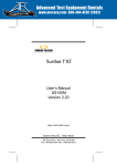
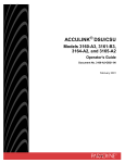
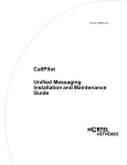
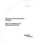
LED Indicator and Diagnostics
The DDI MUX has 15 LEDs to check or monitor its status.
Figure 8 DDI MUX LEDs
Test Mode (TM)
Data Set Ready (DSR)
Data Carrier Detect (DCD)
Clear to Send (CTS)
Request to Send (RTS)
Receive Data (RxD)
Transmit Data (TxD)
10101
Power
Status
In Service
Loopback Test
Receive LEDs
Transmit LEDs
P0989728 02
TxD
RxD
RTS
CTS
DCD
DSR
TM
Installing the DDI MUX
33
The LEDs light under the following conditions:
Table 6 DDI MUX LEDs
LED
Description
TxD
(Transmit data)
The LED flashes at a rate equal to the number of zeros in the data received from the
DTE and transmitted over the network. The speed of the flashes is an indication of
the speed of the data sent over the network.
RxD
(Receive data)
The LED flashes at a rate equal to the number of zeros in the data received from the
network and transmitted to the DTE. The speed of the flashes is an indication of the
speed of the data sent over the network.
RTS
(Request to Send)
The LED lights when the DTE requests permission from the DDI MUX to send data.
CTS
(Clear to Send)
The LED lights when the DDI MUX is signaling the DTE that it has permission to
send data.
DCD
(Data Carrier Detect)
The LED lights when the Business Communications Manager is receiving a carrier
signal.
DSR
(Data Set Ready)
The LED lights when the DDI MUX is ready to communicate.
TM
(Test Mode)
The LED lights when the DDI MUX is signaling to the DTE that it detects a test
condition.
(Power)
On indicates that the DTM is receiving +5 volts.
(Status)
On indicates there is data communication between the DDI MUX and the MSC card.
In Service
Flashing indicates that the T1 trunks are out of service because a loopback test is
running or the DDI MUX is initializing.
Loopback
On indicates a continuity loopback test is running on the T1 link.
Receive Alarm
On indicates a problem with the received digital transmission on the T1 link. This
half-duplex link does not work.
Receive Error
On indicates a small error as a result of degraded digital transmission on the T1 link.
Possible causes are an ohmic connection, water ingress, or too long a loop.
Transmit Alarm
On indicates the DDI MUX cannot transmit on the T1 link. The DDI MUX sends an
Alarm indication signal (AIS) to the terminating switch. This half-duplex link does not
work.
Transmit Error
On indicates the DDI MUX is sending a remote alarm indication (RAI) carrier failure
alarm (CFA) to the terminating switch. If the Transmit Alarm is not on, this error
indicates a far-end or cable problem.
DDI MUX Installation Guide
34
Installing the DDI MUX
Installation troubleshooting
The Business Communications Manager media bay modules are working when both the
(Power) and
•
(Status) LEDs on the modules are on solid.
If the
(Power) LED does not light, refer to “Shutting down the system” on page 19. After
the Business Communications Manager is correctly shut down, remove the module and check
the connectors at the back of the module for dirt or loose connections.
After you reinstall the module, if the LED still does not light, install a different module into
that bay to check for a possible fault in the backplate. If the second module works, assume that
the first module is defective and replace it with a new module.
•
•
•
If the
(Power) LED lights, but the
(Status) light does not light, or continues to blink,
wait 10 minutes to allow for information download. If the light continues to blink, power
down the system and check the DIP switch settings on the module. This might also indicate a
loose cable at the back of the media bay module housing.
If the LEDs are on solid, but the module cannot communicate or be communicated with, check
the Unified Manager settings for the module.
If all of the LEDs are flashing continuously, the DDI MUX is initializing.
Problems with equipment
Before continuing, make sure that you have followed the procedures for installing the DDI MUX.
DCD LED is not solid and DSR LED is solid.
There is no network connection. Check the status of the network connection (T1 connection).
The transmit data and/or the receive data LED is not blinking and DSR, RTS and
CTS LEDs are on.
Data not sent over the network.
•
•
•
•
•
Check the DTE configuration.
Check the connection between the DTE and the DDI MUX.
Check that you set the type setting for the data module to DDI MUX.
Check that the interface standard is the same for the DDI MUX and DTE and that you use the
appropriate cable.
Invert the clock.
P0989728 02
Installing the DDI MUX
35
All data not received at the far end.
Problem indicates invalid clocking between the DDI MUX and the DTE.
•
•
•
•
•
•
•
Check if TxD and RxD LEDs are blinking.
Check the DTE configuration.
Check the DDI MUX clock source using Unified Manager.
Check data inversion configuration at the far end.
Make sure the network supports the data rate per channel.
Make sure data rate per channel and channels assigned are equal to the far end.
Invert the clock.
DCE, DSR and CTS LEDs are off
•
•
Check configuration of the DDI MUX.
Check the T1 cable.
Power, Status and CTS LEDs are on solid and In Service, Loopback Test, Receive
and Transmit LEDs are blinking
Check the DS30 channel assigned to the DDI MUX and the DS30 Split used by the Business
Communications Manager system.
•
•
If the Business Communications Manager system uses a 2/6 DS30 Split, the DDI MUX must
be assigned to a DS30 channel from 2 to 6.
If the Business Communications Manager system uses a 3/5 DS30 Split, the DDI MUX must
be assigned to a DS30 channel from 2 to 5.
Make sure there is no other media bay module using the DS30 channel assigned to the DDI
MUX or the next DS30 channel. For example, if the dip switch settings on the DDI MUX are
set to DS30 channel 3, no other media bay module can use DS30 channels 3 or 4.
For more information about the DS30 Split, refer to the Business Communications Manager
Programming Operations Guide.
TM is on, data is not transmitting
•
Loopback is active. Program Loopback to None.
Alarm 101 sounds
There is a mismatch of type of hardware connected to the Business Communications Manager and
type of hardware defined in programming.
•
Check that the Programmed Bus Type setting is Data Module.
DDI MUX Installation Guide
36
Installing the DDI MUX
Programming Record
Complete the following DDI MUX Programming Record before you start programming.
DDI MUX Programming Record
Work Site: _____________________________________________________________________
Address: ______________________________ Telephone Number: _________________
______________________________ Installation Date: ___________________
______________________________ Installer: __________________________
Notes:
______________________________________________________________________
Configuration parameters
Protocol
V.35
❑
Fixed Access
Line ____ Channel ____
Line ____ Channel ____
Line ____ Channel ____
Line ____ Channel ____
Line ____ Channel ____
Line ____ Channel ____
Line ____ Channel ____
Line ____ Channel ____
Line ____ Channel ____
Line ____ Channel ____
Line ____ Channel ____
Line ____ Channel ____
Line ____ Channel ____
Line ____ Channel ____
Line ____ Channel ____
Line ____ Channel ____
Line ____ Channel ____
Line ____ Channel ____
Line ____ Channel ____
Line ____ Channel ____
Line ____ Channel ____
Line ____ Channel ____
Line ____ Channel ____
Line ____ Channel ____
Loopback State
Off
Manual DTE
Manual DS30
Automatic DTE
P0989728 02
❑
❑
❑
❑