1
BayRS Version 14.20
Part No. 308659-14.20 Rev 00
August 2000
4401 Great America Parkway
Santa Clara, CA 95054
Using the Bay Command
Console (BCC)
Copyright © 2000 Nortel Networks
All rights reserved. Printed in the USA. August 2000.
The information in this document is subject to change without notice. The statements, configurations, technical data,
and recommendations in this document are believed to be accurate and reliable, but are presented without express or
implied warranty. Users must take full responsibility for their applications of any products specified in this document.
The information in this document is proprietary to Nortel Networks NA Inc.
The software described in this document is furnished under a license agreement and may only be used in accordance
with the terms of that license. A summary of the Software License is included in this document.
Trademarks
NORTEL NETWORKS is a trademark of Nortel Networks.
Nortel Networks, AN, BCN, BLN, BN, and FRE are registered trademarks and ANH, ARN, ASN, BayRS, BayStack,
BCC, Passport, and System 5000 are trademarks of Nortel Networks.
All other trademarks and registered trademarks are the property of their respective owners.
Restricted Rights Legend
Use, duplication, or disclosure by the United States Government is subject to restrictions as set forth in subparagraph
(c)(1)(ii) of the Rights in Technical Data and Computer Software clause at DFARS 252.227-7013.
Notwithstanding any other license agreement that may pertain to, or accompany the delivery of, this computer
software, the rights of the United States Government regarding its use, reproduction, and disclosure are as set forth in
the Commercial Computer Software-Restricted Rights clause at FAR 52.227-19.
Statement of Conditions
In the interest of improving internal design, operational function, and/or reliability, Nortel Networks NA Inc. reserves
the right to make changes to the products described in this document without notice.
Nortel Networks NA Inc. does not assume any liability that may occur due to the use or application of the product(s)
or circuit layout(s) described herein.
Portions of the code in this software product may be Copyright © 1988, Regents of the University of California. All
rights reserved. Redistribution and use in source and binary forms of such portions are permitted, provided that the
above copyright notice and this paragraph are duplicated in all such forms and that any documentation, advertising
materials, and other materials related to such distribution and use acknowledge that such portions of the software were
developed by the University of California, Berkeley. The name of the University may not be used to endorse or
promote products derived from such portions of the software without specific prior written permission.
SUCH PORTIONS OF THE SOFTWARE ARE PROVIDED “AS IS” AND WITHOUT ANY EXPRESS OR
IMPLIED WARRANTIES, INCLUDING, WITHOUT LIMITATION, THE IMPLIED WARRANTIES OF
MERCHANTABILITY AND FITNESS FOR A PARTICULAR PURPOSE.
In addition, the program and information contained herein are licensed only pursuant to a license agreement that
contains restrictions on use and disclosure (that may incorporate by reference certain limitations and notices imposed
by third parties).
Nortel Networks NA Inc. Software License Agreement
NOTICE: Please carefully read this license agreement before copying or using the accompanying software or
installing the hardware unit with pre-enabled software (each of which is referred to as “Software” in this Agreement).
BY COPYING OR USING THE SOFTWARE, YOU ACCEPT ALL OF THE TERMS AND CONDITIONS OF
THIS LICENSE AGREEMENT. THE TERMS EXPRESSED IN THIS AGREEMENT ARE THE ONLY TERMS
UNDER WHICH NORTEL NETWORKS WILL PERMIT YOU TO USE THE SOFTWARE. If you do not accept
ii
308659-14.20 Rev 00
these terms and conditions, return the product, unused and in the original shipping container, within 30 days of
purchase to obtain a credit for the full purchase price.
1. License Grant. Nortel Networks NA Inc. (“Nortel Networks”) grants the end user of the Software (“Licensee”) a
personal, nonexclusive, nontransferable license: a) to use the Software either on a single computer or, if applicable, on
a single authorized device identified by host ID, for which it was originally acquired; b) to copy the Software solely
for backup purposes in support of authorized use of the Software; and c) to use and copy the associated user manual
solely in support of authorized use of the Software by Licensee. This license applies to the Software only and does not
extend to Nortel Networks Agent software or other Nortel Networks software products. Nortel Networks Agent
software or other Nortel Networks software products are licensed for use under the terms of the applicable Nortel
Networks NA Inc. Software License Agreement that accompanies such software and upon payment by the end user of
the applicable license fees for such software.
2. Restrictions on use; reservation of rights. The Software and user manuals are protected under copyright laws.
Nortel Networks and/or its licensors retain all title and ownership in both the Software and user manuals, including
any revisions made by Nortel Networks or its licensors. The copyright notice must be reproduced and included with
any copy of any portion of the Software or user manuals. Licensee may not modify, translate, decompile, disassemble,
use for any competitive analysis, reverse engineer, distribute, or create derivative works from the Software or user
manuals or any copy, in whole or in part. Except as expressly provided in this Agreement, Licensee may not copy or
transfer the Software or user manuals, in whole or in part. The Software and user manuals embody Nortel Networks’
and its licensors’ confidential and proprietary intellectual property. Licensee shall not sublicense, assign, or otherwise
disclose to any third party the Software, or any information about the operation, design, performance, or
implementation of the Software and user manuals that is confidential to Nortel Networks and its licensors; however,
Licensee may grant permission to its consultants, subcontractors, and agents to use the Software at Licensee’s facility,
provided they have agreed to use the Software only in accordance with the terms of this license.
3. Limited warranty. Nortel Networks warrants each item of Software, as delivered by Nortel Networks and properly
installed and operated on Nortel Networks hardware or other equipment it is originally licensed for, to function
substantially as described in its accompanying user manual during its warranty period, which begins on the date
Software is first shipped to Licensee. If any item of Software fails to so function during its warranty period, as the sole
remedy Nortel Networks will at its discretion provide a suitable fix, patch, or workaround for the problem that may be
included in a future Software release. Nortel Networks further warrants to Licensee that the media on which the
Software is provided will be free from defects in materials and workmanship under normal use for a period of 90 days
from the date Software is first shipped to Licensee. Nortel Networks will replace defective media at no charge if it is
returned to Nortel Networks during the warranty period along with proof of the date of shipment. This warranty does
not apply if the media has been damaged as a result of accident, misuse, or abuse. The Licensee assumes all
responsibility for selection of the Software to achieve Licensee’s intended results and for the installation, use, and
results obtained from the Software. Nortel Networks does not warrant a) that the functions contained in the software
will meet the Licensee’s requirements, b) that the Software will operate in the hardware or software combinations that
the Licensee may select, c) that the operation of the Software will be uninterrupted or error free, or d) that all defects
in the operation of the Software will be corrected. Nortel Networks is not obligated to remedy any Software defect that
cannot be reproduced with the latest Software release. These warranties do not apply to the Software if it has been (i)
altered, except by Nortel Networks or in accordance with its instructions; (ii) used in conjunction with another
vendor’s product, resulting in the defect; or (iii) damaged by improper environment, abuse, misuse, accident, or
negligence. THE FOREGOING WARRANTIES AND LIMITATIONS ARE EXCLUSIVE REMEDIES AND ARE
IN LIEU OF ALL OTHER WARRANTIES EXPRESS OR IMPLIED, INCLUDING WITHOUT LIMITATION ANY
WARRANTY OF MERCHANTABILITY OR FITNESS FOR A PARTICULAR PURPOSE. Licensee is responsible
for the security of its own data and information and for maintaining adequate procedures apart from the Software to
reconstruct lost or altered files, data, or programs.
4. Limitation of liability. IN NO EVENT WILL NORTEL NETWORKS OR ITS LICENSORS BE LIABLE FOR
ANY COST OF SUBSTITUTE PROCUREMENT; SPECIAL, INDIRECT, INCIDENTAL, OR CONSEQUENTIAL
DAMAGES; OR ANY DAMAGES RESULTING FROM INACCURATE OR LOST DATA OR LOSS OF USE OR
PROFITS ARISING OUT OF OR IN CONNECTION WITH THE PERFORMANCE OF THE SOFTWARE, EVEN
IF NORTEL NETWORKS HAS BEEN ADVISED OF THE POSSIBILITY OF SUCH DAMAGES. IN NO EVENT
308659-14.20 Rev 00
iii
SHALL THE LIABILITY OF NORTEL NETWORKS RELATING TO THE SOFTWARE OR THIS AGREEMENT
EXCEED THE PRICE PAID TO NORTEL NETWORKS FOR THE SOFTWARE LICENSE.
5. Government Licensees. This provision applies to all Software and documentation acquired directly or indirectly by
or on behalf of the United States Government. The Software and documentation are commercial products, licensed on
the open market at market prices, and were developed entirely at private expense and without the use of any U.S.
Government funds. The license to the U.S. Government is granted only with restricted rights, and use, duplication, or
disclosure by the U.S. Government is subject to the restrictions set forth in subparagraph (c)(1) of the Commercial
Computer Software––Restricted Rights clause of FAR 52.227-19 and the limitations set out in this license for civilian
agencies, and subparagraph (c)(1)(ii) of the Rights in Technical Data and Computer Software clause of DFARS
252.227-7013, for agencies of the Department of Defense or their successors, whichever is applicable.
6. Use of Software in the European Community. This provision applies to all Software acquired for use within the
European Community. If Licensee uses the Software within a country in the European Community, the Software
Directive enacted by the Council of European Communities Directive dated 14 May, 1991, will apply to the
examination of the Software to facilitate interoperability. Licensee agrees to notify Nortel Networks of any such
intended examination of the Software and may procure support and assistance from Nortel Networks.
7. Term and termination. This license is effective until terminated; however, all of the restrictions with respect to
Nortel Networks’ copyright in the Software and user manuals will cease being effective at the date of expiration of the
Nortel Networks copyright; those restrictions relating to use and disclosure of Nortel Networks’ confidential
information shall continue in effect. Licensee may terminate this license at any time. The license will automatically
terminate if Licensee fails to comply with any of the terms and conditions of the license. Upon termination for any
reason, Licensee will immediately destroy or return to Nortel Networks the Software, user manuals, and all copies.
Nortel Networks is not liable to Licensee for damages in any form solely by reason of the termination of this license.
8. Export and Re-export. Licensee agrees not to export, directly or indirectly, the Software or related technical data
or information without first obtaining any required export licenses or other governmental approvals. Without limiting
the foregoing, Licensee, on behalf of itself and its subsidiaries and affiliates, agrees that it will not, without first
obtaining all export licenses and approvals required by the U.S. Government: (i) export, re-export, transfer, or divert
any such Software or technical data, or any direct product thereof, to any country to which such exports or re-exports
are restricted or embargoed under United States export control laws and regulations, or to any national or resident of
such restricted or embargoed countries; or (ii) provide the Software or related technical data or information to any
military end user or for any military end use, including the design, development, or production of any chemical,
nuclear, or biological weapons.
9. General. If any provision of this Agreement is held to be invalid or unenforceable by a court of competent
jurisdiction, the remainder of the provisions of this Agreement shall remain in full force and effect. This Agreement
will be governed by the laws of the state of California.
Should you have any questions concerning this Agreement, contact Nortel Networks, 4401 Great America Parkway,
P.O. Box 58185, Santa Clara, California 95054-8185.
LICENSEE ACKNOWLEDGES THAT LICENSEE HAS READ THIS AGREEMENT, UNDERSTANDS IT, AND
AGREES TO BE BOUND BY ITS TERMS AND CONDITIONS. LICENSEE FURTHER AGREES THAT THIS
AGREEMENT IS THE ENTIRE AND EXCLUSIVE AGREEMENT BETWEEN NORTEL NETWORKS AND
LICENSEE, WHICH SUPERSEDES ALL PRIOR ORAL AND WRITTEN AGREEMENTS AND
COMMUNICATIONS BETWEEN THE PARTIES PERTAINING TO THE SUBJECT MATTER OF THIS
AGREEMENT. NO DIFFERENT OR ADDITIONAL TERMS WILL BE ENFORCEABLE AGAINST NORTEL
NETWORKS UNLESS NORTEL NETWORKS GIVES ITS EXPRESS WRITTEN CONSENT, INCLUDING AN
EXPRESS WAIVER OF THE TERMS OF THIS AGREEMENT.
iv
308659-14.20 Rev 00
Contents
Preface
Before You Begin .............................................................................................................xiii
Text Conventions .............................................................................................................xiv
Acronyms .........................................................................................................................xvi
Hard-Copy Technical Manuals ........................................................................................xvii
How to Get Help ............................................................................................................ xviii
Chapter 1
Overview of the BCC
Introduction .....................................................................................................................1-2
Platform Requirements ...................................................................................................1-3
Number of BCC Sessions ...............................................................................................1-3
Multilevel Access ............................................................................................................1-3
Terminology and Concepts .............................................................................................1-4
Configuration Hierarchy ............................................................................................1-4
Configuration Context ..............................................................................................1-6
Objects and Instances ..............................................................................................1-8
BCC Instance Identifier ......................................................................................1-8
Global (Box-Wide) Objects ................................................................................1-8
Physical Device Objects ....................................................................................1-9
Parameters .............................................................................................................1-11
Required ..........................................................................................................1-11
Derived ............................................................................................................1-11
Optional ...........................................................................................................1-11
Chapter 2
Getting Started with the BCC
Entering and Exiting the BCC Interface ..........................................................................2-2
Displaying Your Location in Configuration Mode ............................................................2-4
308659-14.20 Rev 00
v
Navigating in Configuration Mode ...................................................................................2-4
Navigating with the back Command .........................................................................2-4
Navigating with Configuration Commands ...............................................................2-5
Moving Back One or More Levels ......................................................................2-5
Moving Back to Root Level ................................................................................2-6
Moving Forward One or More Levels .................................................................2-6
Moving to Any Context in the Device Configuration ...........................................2-7
Displaying Configuration Data ........................................................................................2-9
Displaying Current/Active Configuration Data ..........................................................2-9
Displaying Configured Objects ........................................................................2-12
Displaying Configured Parameter Values ........................................................2-18
Displaying Configuration Choices ..........................................................................2-22
Displaying the Total Device Configuration Tree (All Available Choices) ...........2-23
Displaying Choices Available from the Current Context ..................................2-24
Displaying Choices Available at All Subcontext Levels ....................................2-24
Displaying Parameter Definitions ...........................................................................2-25
Saving Displayed Configuration Data .....................................................................2-28
Displaying Help on System Commands .......................................................................2-28
Displaying Help on show Commands ...........................................................................2-29
Chapter 3
Entering Commands and Using Command Files
Entering Commands .......................................................................................................3-2
Using Command Abbreviations ................................................................................3-2
Recalling Commands ...............................................................................................3-2
Using Command Completion ...................................................................................3-3
Editing Command Lines ...........................................................................................3-3
Entering Multiple Commands on a Line ...................................................................3-4
Continuing a Command Line ....................................................................................3-5
System Commands ........................................................................................................3-6
Configuration Command Syntax .....................................................................................3-6
Command Syntax Requirements .............................................................................3-6
Using Basic (Full) Syntax .........................................................................................3-7
Using Default Syntax ................................................................................................3-8
Using Abbreviated Syntax ........................................................................................3-9
vi
308659-14.20 Rev 00
Specifying Parameter Values ...................................................................................3-9
Required, Derived, and Other Parameters ......................................................3-10
Specifying Multiple Parameter-Value Pairs ......................................................3-10
Specifying Multiple Values for One Parameter ................................................3-10
Parameter Range Validation ............................................................................3-11
Specifying Name or String Values ...................................................................3-11
Disabling, Reenabling, and Deleting a Configured Object .....................................3-12
Creating and Using BCC Files ......................................................................................3-13
Saving Commands and Displays to a File on a Workstation ..................................3-13
Saving Configuration Commands to a File on a Device .........................................3-14
Adding Comments to a Command File ..................................................................3-14
Importing Configuration Commands from a File ....................................................3-15
Saving the Active Configuration as a Bootable File ...............................................3-16
Chapter 4
Tutorial: Configuring a Nortel Networks Router
Creating and Modifying a Device Configuration .............................................................4-2
Sample Router Configuration .........................................................................................4-2
Disabling a Configured Object ......................................................................................4-15
Enabling a Configured Object .......................................................................................4-16
Deleting a Configured Object .......................................................................................4-17
Appendix A
Multilevel Access
Introduction .................................................................................................................... A-2
Multilevel Access Login ................................................................................................. A-2
How Access Is Granted ................................................................................................. A-2
Access Privileges .......................................................................................................... A-3
Access Security ............................................................................................................. A-4
Sharing Access Profiles ................................................................................................. A-4
Configuring Multilevel Access ........................................................................................ A-4
Configuring Access ................................................................................................. A-5
Configuring User ..................................................................................................... A-6
Configuring Group ................................................................................................... A-7
Configuring Audit ..................................................................................................... A-8
308659-14.20 Rev 00
vii
Disabling or Deleting Users and Groups ....................................................................... A-8
BCC Lock Messages ..................................................................................................... A-9
Appendix B
System Commands
Appendix C
TCL Support
Appendix D
System show Commands
show access .................................................................................................................. D-2
show console ................................................................................................................. D-4
show hardware .............................................................................................................. D-7
show interface ................................................................................................................ D-9
show process ............................................................................................................... D-10
show system ................................................................................................................ D-13
Appendix E
Syntax for Module Location
Appendix F
BN Console Slot Election
Introduction .....................................................................................................................F-2
Using the BCC to Customize Console Slot Election .......................................................F-2
Disabling and Reenabling Console Slot Election ............................................................F-3
Console Slot Election Error Message .............................................................................F-4
Appendix G
BCC Board Types
Introduction .................................................................................................................... G-2
AN and ANH Board Types ............................................................................................. G-2
ARN Board Types .......................................................................................................... G-5
ASN Board Types .......................................................................................................... G-6
BLN and BCN Board Types ........................................................................................... G-7
Passport 2430 Board Types ........................................................................................... G-9
Passport 5430 Board Types ........................................................................................... G-9
System 5000 Board Types ........................................................................................... G-10
Index
viii
308659-14.20 Rev 00
Figures
Figure 1-1.
Technician Interface and the BCC Interface .............................................1-2
Figure 1-2.
Sample BCC Configuration ......................................................................1-5
Figure 1-3.
Configuring IP and RIP on an Ethernet Interface ....................................1-6
Figure 1-4.
Location or Context in Configuration Mode ..............................................1-7
Figure 2-1.
Moving Away from Root Level ..................................................................2-7
Figure 2-2.
Navigating to an Object in the Configuration ...........................................2-8
Figure 2-3.
Navigating with the BCC Recursive Search Feature ...............................2-9
Figure 2-4.
Objects You Can Configure at the Next (Subcontext) Level ...................2-24
Figure 4-1.
Sample BCC Configuration (BCN Router) ...............................................4-3
Figure 4-2.
Typical BCC Configuration Cycle .............................................................4-4
Figure A-1.
Configurable Multilevel Access Objects .................................................. A-5
308659-14.20 Rev 00
ix
Tables
Table 2-1.
Help for BCC System Commands .........................................................2-28
Table 3-1.
Keystrokes for Editing BCC Command Lines ...........................................3-3
Table 3-2.
BCC Commands for Disabling, Reenabling, and Deleting .....................3-12
Table A-1.
Access Parameter Options ..................................................................... A-5
Table A-2.
User Parameter Options ......................................................................... A-6
Table A-3.
Group Parameter Options ....................................................................... A-7
Table A-4.
Audit Parameter Options ......................................................................... A-8
Table B-1.
System Commands ................................................................................. B-2
Table E-1.
Syntax for Specifying Module Location per Device ................................. E-1
Table G-1.
BCC Board Types: AN and ANH Modules .............................................. G-2
Table G-2.
BCC Board Types: ARN Modules ........................................................... G-5
Table G-3.
BCC Board Types: ASN Modules ........................................................... G-6
Table G-4.
BCC Board Types: BLN and BCN Modules ............................................ G-7
Table G-5.
BCC Board Types: Passport 2430 Modules ............................................ G-9
Table G-6.
BCC Board Types: Passport 5430 Modules ............................................ G-9
Table G-7.
BCC Board Types: System 5000 Modules ............................................ G-10
308659-14.20 Rev 00
xi
Preface
The Bay Command Console (BCC™) is a command-line interface for configuring
Nortel Networks™ devices. If you are responsible for configuring and managing
Nortel Networks AN®, ANH™, ARN™, ASN™, BN® (BCN® and BLN®), Passport™
2430, Passport 5430, and System 5000™ routers, read this guide to learn how to
use the BCC.
Before You Begin
Before using this guide, you must complete the following procedures. For a new
router:
•
Install the router (see the installation guide that came with your router).
•
Connect the router to the network and create a pilot configuration file (see
Quick-Starting Routers, Configuring BayStack Remote Access, or Connecting
ASN Routers to a Network).
Make sure that you are running the latest version of Nortel Networks BayRS™ and
Site Manager software. For information about upgrading BayRS and Site
Manager, see the upgrading guide for your version of BayRS.
308659-14.20 Rev 00
xiii
Using the Bay Command Console (BCC)
Text Conventions
This guide uses the following text conventions:
angle brackets (< >)
Indicate that you choose the text to enter based on the
description inside the brackets. Do not type the
brackets when entering the command.
Example: If the command syntax is:
ping <ip_address>, you enter:
ping 192.32.10.12
bold text
Indicates command names and options and text that
you need to enter.
Example: Enter show ip {alerts | routes}.
Example: Use the dinfo command.
braces ({})
Indicate required elements in syntax descriptions
where there is more than one option. You must choose
only one of the options. Unless explicitly instructed to
do so, do not type the braces when entering the
command.
Example: If the command syntax is:
show ip {alerts | routes}, you must enter either:
show ip alerts or show ip routes, but not both.
If the command sets a parameter value consisting of
multiple elements, you must type the braces as part of
the command if instructed to do so.
Example:
severity-mask {fault warning info}
brackets ([ ])
Indicate optional elements in syntax descriptions. Do
not type the brackets when entering the command.
Example: If the command syntax is:
show ip interfaces [-alerts], you can enter either:
show ip interfaces or show ip interfaces -alerts.
xiv
308659-14.20 Rev 00
Preface
ellipsis points (. . . )
Indicate that you repeat the last element of the
command as needed.
Example: If the command syntax is:
ethernet/2/1 [<parameter> <value>] . . . , you enter
ethernet/2/1 and as many parameter-value pairs as
needed.
italic text
Indicates new terms, book titles, and variables in
command syntax descriptions. Where a variable is two
or more words, the words are connected by an
underscore.
Example: If the command syntax is:
show at <valid_route>
valid_route is one variable and you substitute one value
for it.
screen text
Indicates system output, for example, prompts and
system messages.
Example: Set Nortel Networks Trap Monitor
Filters
separator ( > )
Shows menu paths.
Example: Protocols > IP identifies the IP option on the
Protocols menu.
vertical line ( | )
Separates choices for command keywords and
arguments. Enter only one of the choices. Do not type
the vertical line when entering the command.
Example: If the command syntax is:
show ip {alerts | routes}, you enter either:
show ip alerts or show ip routes, but not both.
308659-14.20 Rev 00
xv
Using the Bay Command Console (BCC)
Acronyms
This guide uses the following acronyms:
xvi
ARP
Address Resolution Protocol
ATM
asynchronous transfer mode
BofL
Breath of Life
DCM
data collection module
DRAM
dynamic random access memory
FDDI
Fiber Distributed Data Interface
GAME
Gate Access Management Entity
IP
Internet Protocol
IPX
Internetwork Packet Exchange
ISDN
Integrated Services Digital Network
LAN
local area network
MIB
Management Information Base
MAC
media access control
NVFS
nonvolatile file system
NVRAM
nonvolatile random access memory
OSPF
Open Shortest Path First
PCI
peripheral component interconnect
PMC
PCI mezzanine card
RADIUS
Remote Access Dial-In User Services
RIP
Routing Information Protocol
SNMP
Simple Network Management Protocol
SRM-L
system resource module-link
TCL
Tool Command Language
TCP/IP
Transmission Control Protocol/Internet Protocol
TFTP
Trivial File Transfer Protocol
308659-14.20 Rev 00
Preface
VNR
Virtual Network Routing
WAN
wide area network
Hard-Copy Technical Manuals
For more information about using the BCC to configure or monitor (show)
behavior of a specific BayRS service, refer to the latest edition of the Task Map.
You can print selected technical manuals and release notes free, directly from the
Internet. Go to support.baynetworks.com/library/tpubs/. Find the product for
which you need documentation. Then locate the specific category and model or
version for your hardware or software product. Using Adobe Acrobat Reader, you
can open the manuals and release notes, search for the sections you need, and print
them on most standard printers. You can download Acrobat Reader free from the
Adobe Systems Web site, www.adobe.com.
You can purchase selected documentation sets, CDs, and technical publications
through the collateral catalog. The catalog is located on the World Wide Web at
support.baynetworks.com/catalog.html and is divided into sections arranged
alphabetically:
•
The “CD ROMs” section lists available CDs.
•
The “Guides/Books” section lists books on technical topics.
•
The “Technical Manuals” section lists available printed documentation sets.
308659-14.20 Rev 00
xvii
Using the Bay Command Console (BCC)
How to Get Help
If you purchased a service contract for your Nortel Networks product from a
distributor or authorized reseller, contact the technical support staff for that
distributor or reseller for assistance.
If you purchased a Nortel Networks service program, contact one of the following
Nortel Networks Technical Solutions Centers:
xviii
Technical Solutions Center
Telephone Number
Billerica, MA
800-2LANWAN (800-252-6926)
Santa Clara, CA
800-2LANWAN (800-252-6926)
Valbonne, France
33-4-92-96-69-68
Sydney, Australia
61-2-9927-8800
Tokyo, Japan
81-3-5740-1700
308659-14.20 Rev 00
Chapter 1
Overview of the BCC
This chapter provides information about the following topics:
Topic
Page
Introduction
1-2
Platform Requirements
1-3
Number of BCC Sessions
1-3
Multilevel Access
1-3
Terminology and Concepts
1-4
308659-14.20 Rev 00
1-1
Using the Bay Command Console (BCC)
Introduction
The BCC is a command-line interface for configuring Nortel Networks devices.
After logging on to a device, you access the BCC by entering the bcc command at
the Technician Interface prompt (Figure 1-1).
Technician
Interface
Login
Access
the BCC
BCC
BCC0001B
Figure 1-1.
Technician Interface and the BCC Interface
From the BCC prompt, you can:
•
Execute any system command not classified as “Technician Interface only”
(see Appendix B, “System Commands”).
•
Execute configuration commands to perform tasks such as creating or deleting
IP interfaces on the router. Enter BCC configuration mode by entering the
config command at the BCC prompt.
Note: For a list of services you can configure using the BCC, see the Release
Notes. You can obtain a complete hierarchical listing of all objects
configurable on a device by entering the help tree -all command at any BCC
prompt.
1-2
308659-14.20 Rev 00
Overview of the BCC
Platform Requirements
The BCC runs on AN, ANH, ARN, ASN, System 5000, and BN platforms
including ARE, FRE®, and FRE-2 processor modules. Each slot must have:
•
16 MB of dynamic RAM (DRAM)
•
2 MB of free memory space available when you start the BCC
If you try to start the BCC with insufficient DRAM or free memory on a slot, the
BCC returns an error message. In that case, use Site Manager instead of the BCC.
Number of BCC Sessions
You can open one BCC session per slot in read-write (configuration) mode. Other
users can open additional BCC sessions in read-only (nonconfiguration) mode on
the same slot, depending on available memory. Each BCC session is mutually
exclusive. If you make a change during a BCC session in read-write mode, this
change does not appear in other BCC sessions.
Multilevel Access
Multilevel access adds a third login level, that of Operator, to the existing Manager
and User login levels of the BCC. With multilevel access, multiple users (each
with a distinct user name and password) can access the router simultaneously.
Multilevel access allows you to:
•
Add multiple user names, passwords, and access privileges to the router
•
Manage the distribution of user names, passwords, and access privileges from
the BCC
•
View event logs showing each BCC command issued and the user responsible
for issuing the command
For more information on how to configure and use multilevel access features,
refer to Appendix A, “Multilevel Access.” For a list of system commands and the
privilege level required to execute them, refer to Appendix B, “System
Commands.”
308659-14.20 Rev 00
1-3
Using the Bay Command Console (BCC)
Terminology and Concepts
This section describes key terms and concepts of the BCC interface.
Configuration Hierarchy
The BCC configuration hierarchy begins at a root-level object, called box for
AN/ANH, ARN, and BN platforms, and stack for ASN and System 5000
platforms. Under the root-level object are branch objects such as interfaces and
protocols that fan out from root level in a tree hierarchy.
You use the help tree -all and show config -all commands to display the
configuration hierarchy of a Nortel Networks router:
•
The help tree -all command displays the hierarchy of every object you can
configure. (These are the configuration choices you can make. These are not
objects already configured.)
•
The show config -all command displays the hierarchy of objects you have
actually configured.
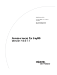
Figure 1-2 illustrates a sample BCC configuration for an AN, BN, or ARN router.
1-4
308659-14.20 Rev 00
Overview of the BCC
box
(root)
ospf
(protocol)
ip
(protocol)
arp
(protocol)
rip
(protocol)
snmp
(protocol)
telnet
(protocol)
tftp
(protocol)
BOX-WIDE/GLOBAL OBJECTS
(Services supported on all slots)
INTERFACE-SPECIFIC OBJECTS
(Services supported on a specific slot)
ospf/1.2.3.4
(protocol)
ethernet/2/1
(interface)
ip/1.2.3.4/255.0.0.0
(protocol)
ethernet/2/2
(interface)
arp/1.2.3.4/1
(protocol)
serial/3/1
(interface)
BCC0012C
Figure 1-2.
308659-14.20 Rev 00
Sample BCC Configuration
1-5
Using the Bay Command Console (BCC)
You use BCC commands to create new objects and to modify or delete objects in
an existing configuration hierarchy. You begin at root level in BCC configuration
mode and navigate to objects in the device configuration tree.
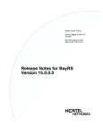
For example, on a BLN router, you can use BCC commands to add a new physical
interface (such as Ethernet) on box, add IP to the Ethernet interface, and then add
RIP to IP on that interface. Figure 1-3 shows the sequence of commands necessary
to build this configuration.
box
box# ethernet/2/1
Ethernet
Slot 2
Connection 1
ethernet/2/1# ip address 1.2.3.4 mask 255.0.0.0
IP
Address 1.2.3.4
Mask 255.0.0.0
ip/1.2.3.4/255.0.0.0# rip
rip/1.2.3.4
rip/1.2.3.4#
BCC0017A
Figure 1-3.
Configuring IP and RIP on an Ethernet Interface
Configuration Context
Your working location within the BCC configuration tree is referred to as the
context. Just as a UNIX file system has a current working directory within which
you can add, modify, or delete files, the BCC configuration tree has a current
working context, within which you can add, modify, disable, reenable, or delete
objects.
1-6
308659-14.20 Rev 00
Overview of the BCC
The BCC displays the context of an object in terms of its location along a path that
begins at the root level of the device configuration tree. Each semicolon in the
path marks a transition from one level to the next branch level in the device
configuration tree. Using a semicolon is also equivalent to pressing [Return] at the
end of a command, effectively starting a new command line.
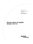
For example, if you configure an IP interface (address 1.2.3.4, mask 255.0.0.0) on
ethernet/2/1 of a BLN router, the BCC displays its location as
box; ethernet/2/1; ip/1.2.3.4/255.0.0.0 (Figure 1-4).
box
box# ethernet/2/1
ethernet/2/1
ethernet/2/1# ip address 1.2.3.4 mask 255.0.0.0
ip/1.2.3.4/255.0.0.0
ip/1.2.3.4/255.0.0.0#
BCC0017B
Figure 1-4.
308659-14.20 Rev 00
Location or Context in Configuration Mode
1-7
Using the Bay Command Console (BCC)
Objects and Instances
In BCC terminology, configurable entities are referred to as objects of a particular
class, each of which constitutes an instance:
•
An object is a configurable physical or logical entity such as a physical
interface or a protocol on an interface. Every configurable object belongs to a
specific class that defines its characteristics.
•
A class is a template for a configurable object (such as Ethernet or the
protocol IP). When you add a new object to the configuration of a device, the
BCC creates a copy (instance) of the appropriate template.
•
An instance is an object uniquely identifiable within the total device
configuration. Each instance is identified by its BCC instance identifier.
BCC Instance Identifier
A BCC instance identifier uniquely identifies a single instance of an object
configured on a device. The BCC instance ID consists typically of the name of the
object, combined with the values you specify for its required parameters. For
example, the BCC instance ID for an Ethernet interface on a BN platform consists
of ethernet/<slot>/<connector>, as in ethernet/2/1; the BCC instance ID for an
Ethernet interface on an ASN platform consists of
ethernet/<slot>/<module>/<connector>, as in ethernet/1/2/2.
A configurable object may also have required parameters that do not become part
of its BCC instance ID. For example, the global OSPF object has a required
router-id parameter that does not become part of the instance ID.
Each object has its own requirements for unique instance identification within the
total device configuration.
Global (Box-Wide) Objects
Global (box-wide) objects provide services uniformly to all slots of a network
device. Examples include global IP, BGP, TCP, SNMP, FTP, TFTP, and Telnet.
Some protocols, such as IP, RIP, and OSPF, have global and interface-level
objects.
1-8
308659-14.20 Rev 00
Overview of the BCC
Physical Device Objects
The following sections provide BCC terms for the physical device.
Box and Stack
The BCC uses the term box or stack to identify the root level of the BCC
configuration tree for a Nortel Networks device. Every box or stack object has a
type parameter. The value assigned to the type parameter identifies the type of
Nortel Networks device chassis:
type Value
Router Model
an
AN/ANH
arn
ARN
asn
ASN
freln
BLN
frecn
BCN
lite
Passport 2430
fbr4slot
Passport 5430
sys5000
System 5000
Board
The BCC uses the term board to identify any logic or circuit board in a Nortel
Networks device. Each board typically occupies a slot in a network device. On
some Nortel Networks products, one board may contain another board such as an
RMON data collection module (DCM). All board objects have a type parameter
that identifies its hardware type. For example, “qenf” is the value of the type
parameter for a Quad Ethernet with Hardware Filters board.
Note: For board descriptions based on the literal value of the type parameter
for any board object, see the Release Notes.
308659-14.20 Rev 00
1-9
Using the Bay Command Console (BCC)
Module
The BCC uses the term module to identify network media-specific I/O modules
(such as, Ethernet and token ring). Each module has one or more connectors for
attachment to a physical network transmission medium.
Slot
The BCC uses the term slot to identify the location, as well as a physical and
electrical means, for attaching boards to logic and power connections available on
the device chassis. Note the following:
•
Multislot devices such as the BLN or BCN router accommodate a system
module (SRM-L) in one slot, and one link module in each remaining slot.
•
Single-slot devices such as the AN, ANH, ASN, and ARN routers
accommodate one base module (slot 1), which may be augmented by one or
two adapter modules and one expansion module.
Connector
The BCC uses the term connector to identify the physical and electrical means to
interconnect a network device (slot or module) directly or indirectly to a physical
network transmission medium.
Line
The BCC uses the term line to identify the physical (and in some cases, logical)
circuit identified typically by means of a slot, connector, interface type (ethernet,
sync, fddi, and so on), and, where applicable, a channel number (such as with
T1/E1 interface types).
Port
The BCC uses the term port to identify an interface object defined by its type (for
example, an Ethernet port) and location (slot and connector) within a network
device. On a network device, a port is also a logical point of termination for data
sent or received by a specific protocol or application.
1-10
308659-14.20 Rev 00
Overview of the BCC
Interface
The BCC uses the term interface to identify circuitry and digital logic associated
with the interconnection between a physical network medium (such as Ethernet)
and a higher-layer protocol entity (such as IP).
Note: A logical interface is an addressable entity for originating and
terminating connections across an IP network.
Parameters
A parameter is an attribute (or property) of a configurable object. Parameters can
be classified as one of the following:
•
Required
•
Derived
•
Optional
Required
For any BCC object, required parameters are a minimum set of parameters for
which the BCC requires you to supply values. For example, the required
parameters of a physical port are slot and connector.
Derived
Derived parameters are parameters for which the BCC supplies a value. For
example, a derived parameter of the global OSPF object is router-id. In this case,
the BCC derives a value for router-id from the address of the first IP interface
configured on the device.
Optional
Optional parameters are parameters for which you can specify customized values,
replacing any default values set by the system. For example, an optional parameter
of an Ethernet interface is bofl-retries. This parameter normally has a default
value of 5 (5 retries), but you can change this to another numeric value.
308659-14.20 Rev 00
1-11
Chapter 2
Getting Started with the BCC
This chapter provides information about the following topics:
Topic
Page
Entering and Exiting the BCC Interface
2-2
Displaying Your Location in Configuration Mode
2-4
Navigating in Configuration Mode
2-4
Displaying Configuration Data
2-9
Displaying Help on System Commands
2-28
Displaying Help on show Commands
2-29
308659-14.20 Rev 00
2-1
Using the Bay Command Console (BCC)
Entering and Exiting the BCC Interface
To access the BCC interface on a Nortel Networks router:
1.
Open a Technician Interface session with the target router.
For detailed information about opening a Technician Interface session, see
Using Technician Interface Software.
2.
Enter the Manager, Operator, or User command at the login prompt that
appears on your Telnet or console display.
The Manager login allows you to enter any system command and allows
read-write access to the device configuration. The Operator login allows you to
enter only operator-level system commands and allows limited access to the
device configuration. The User login allows you to enter only user-level system
command and allows read-only access to the device configuration. For a list of
system commands and the privilege level required to execute them, refer to
Appendix B, “System Commands.”
3.
Enter bcc at the Technician Interface prompt.
Router1> bcc
Welcome to Bay Command Console!
* To enter configuration mode, type config
* To list all system commands, type?
* To exit the BCC, type exit
bcc>
Note:
Attempting to start the BCC at the Technician Interface prompt before the router
has completed booting up may cause a loading error to occur. Select one of the
following two options to prevent or bypass this error:
2-2
•
To prevent the error condition, wait until the router has completed booting
up before starting the BCC.
•
To bypass the error condition, re-enter the bcc command following the
fault and press [Enter]. The BCC will then start while the router is booting
up.
308659-14.20 Rev 00
Getting Started with the BCC
4.
Enter config at the BCC prompt.
bcc>
box#
config
You enter configuration mode at the root (box) level of the BCC configuration
tree. The prompt ends with a pound symbol (#) if you have read-write
privileges (Manager only), or with a greater than symbol (>) if you have
read-only privileges (Manager or User).
If you enter BCC configuration mode as Manager and want to change your
privilege level for the current session from read-write to read-only, enter
config -read-only. To change Manager privileges back to read-write, enter
config -read-write. You cannot change your privilege level from read-only to
read-write if you logged in as User.
Caution: When you enter BCC configuration commands with read-write
privileges, you immediately modify the device configuration.
5.
When you finish using BCC configuration mode, enter the exit command
at any prompt.
box#
bcc>
6.
exit
When you finish using the BCC, enter the exit command at the BCC
prompt.
bcc> exit
Router1>
Exiting the BCC returns you to the Technician Interface prompt.
For more detailed information about Technician Interface access, login, or logout
procedures, see Using Technician Interface Software.
308659-14.20 Rev 00
2-3
Using the Bay Command Console (BCC)
Displaying Your Location in Configuration Mode
In configuration mode, the BCC displays a context-sensitive prompt. The prompt
identifies the configured object at your current working location within the
configuration hierarchy. For example, after logging in to a BLN router as
Manager, then configuring or navigating to the Ethernet interface on slot 2
connector 1, the BCC displays the following prompt:
ethernet/2/1#
To display the complete path from root level to your current level in the device
configuration tree, enter the pwc (print working context) command.
Example:
rip/192.168.125.34# pwc
box; ethernet/2/1; ip/192.168.125.34/255.255.255.224; rip/
192.168.125.34;
The pwc command displays the BCC instance identifier of each configured object
in the path.
Navigating in Configuration Mode
You can navigate from one object to another in BCC configuration mode by using:
•
The back command
•
Configuration commands
Navigating with the back Command
In BCC configuration mode, use the back command to move a specific number of
levels back toward root level. This is the syntax for the back command:
back [<n> ]
n is the number of levels.
Entering the back command with no argument moves you back one level closer to
root level.
2-4
308659-14.20 Rev 00
Getting Started with the BCC
Example:
rip/192.168.125.34# back
ip/192.168.125.34/255.255.255.224# back
ethernet/2/1#
Entering the back command with an integer moves you from your current
working location, back toward root, the number of levels you specify.
Example:
rip/192.168.125.34# back 2
ethernet/2/1#
In this example, the back 2 command moves you from the current working
location (rip/192.168.125.34), back two levels to ethernet/2/1 (with
ip/192.168.125.34/255.255.255.224 as the intervening level).
Note: If you enter an integer value that exceeds the actual number of levels
back to root (box or stack) level, the BCC returns to root level.
Navigating with Configuration Commands
Using BCC configuration commands, you can:
•
Move back to a previous level
•
Move back to root level
•
Move forward to the next level
•
Move from your current level to any other level in the device configuration
tree
Moving Back One or More Levels
To move from your current working level back one or more levels closer to root
level of the device configuration tree, enter the full BCC instance ID of the desired
object.
Example (go back one level):
rip/192.168.125.34# ip/192.168.125.34/255.255.255.224
ip/192.168.125.34/255.255.255.224#
308659-14.20 Rev 00
2-5
Using the Bay Command Console (BCC)
Example (go back two levels):
rip/192.168.155.151#
ethernet/2/1#
ethernet/2/1
In the second example, the BCC searches back toward root until it finds a context
or level where the object you specified (in this case, ethernet/2/1) exists in the
router configuration tree. The BCC enters the context of this object, and the
prompt displays your new location.
Moving Back to Root Level
You can move back to root level in configuration mode by entering the name of
the object at that level.
For an AN, ANH, ARN, or BN router, enter:
ip/1.2.3.4#
box#
box
For an ASN or System 5000 router, enter:
ip/1.2.3.4#
stack#
stack
Moving Forward One or More Levels
To move from your current working level to the next configured level (Figure 2-1),
enter the BCC instance ID of the desired object.
Example:
box# ethernet/2/1
ethernet/2/1# ip/1.2.3.4/255.0.0.0
ip/1.2.3.4/255.0.0.0# rip
rip/1.2.3.4#
Notice that a slash (/) joins the name and any required parameter values to make a
BCC instance ID for any configured object.
2-6
308659-14.20 Rev 00
Getting Started with the BCC
box
box# eth 2/1
(Starting
context)
ethernet/2/1
ethernet/2/1# ip/1.2.3.4/255.0.0.0
ip/1.2.3.4/255.0.0.0
ip/1.2.3.4/255.0.0.0# rip
rip/1.2.3.4
(Ending
context)
rip/1.2.3.4#
BCC0014B
Figure 2-1.
Moving Away from Root Level
Moving to Any Context in the Device Configuration
To navigate to any configured object, you can specify a full, or absolute, path from
root (box or stack) level at any prompt. When you enter a path, specify the BCC
instance identifier of each object.
Example:
To move from ip/192.168.33.66/255.255.255.0 (on ethernet/2/1) to rip/1.2.3.4 on
ethernet/2/2 (Figure 2-2), enter the following command:
ip/192.168.33.66/255.255.255.0# box;ethernet/2/2;ip/1.2.3.4/255.0.0.0;rip
rip/1.2.3.4#
308659-14.20 Rev 00
2-7
Using the Bay Command Console (BCC)
(Starting context)
ethernet/2/1
ip/192.168.33.66/255.255.255.0
box
ethernet/2/2
rip
ip/1.2.3.4/255.0.0.0
(Ending context)
BCC0009B
Figure 2-2.
Navigating to an Object in the Configuration
The BCC can automatically search backward (recursively) toward root level until
it finds a level where the object you specify first in the command line exists in the
device configuration tree.
Example:
To move from ip/192.168.33.66/255.255.255.0 on ethernet/2/1 to rip/1.2.3.4 on
ethernet/2/2, enter the following command:
ip/192.168.33.66/255.255.255.0#
rip/1.2.3.4#
ethernet/2/2;ip/1.2.3.4/255.0.0.0;rip
In this example, the BCC searches backward to find ethernet/2/2 (specified first in
the command line), and then moves sequentially to the other locations
(ip/1.2.3.4/255.0.0.0 and rip) specified next in the command line.
2-8
308659-14.20 Rev 00
Getting Started with the BCC
(Starting context)
ip/192.168.33.66/255.255.255.0
ethernet/2/1
box
ethernet/2/2
rip
ip/1.2.3.4/255.0.0.0
(Ending context)
BCC0009C
Figure 2-3.
Navigating with the BCC Recursive Search Feature
Displaying Configuration Data
There are several BCC help commands that let you:
•
Display information on objects in the active (actual) device configuration
•
Display information on objects that you can add to the current configuration;
these are ? and help tree [-all]
Displaying Current/Active Configuration Data
With the show config and lso commands, you can display:
•
The current device configuration
•
The operating parameters of each configured object
•
The values set for the parameters of each configured object
308659-14.20 Rev 00
2-9
Using the Bay Command Console (BCC)
The optional arguments you add to these commands depend on what you want to
see, as follows:
Command
Task
show config
Show the configuration of the current object only. (Entered without
any command -<option>, show config does not display objects
configured on the current object.)
Note: Combine the following
command options to customize
show config output.
<BCC_instance_ID>
2-10
Show the configuration of this object (specified by the BCC
instance identifier).
-recursive
Show any dependent objects configured on this (current or
specified) object.
Examples:
• show config -recursive
• show config -compact -recursive
• show config ip/1.2.3.4/255.0.0.0 -recursive
-verbose
Show the configuration including the current (default or
nondefault) value of every parameter of the objects shown.
Examples:
• show config -verbose
• show config -recursive -verbose
• show config ip/1.2.3.4/255.0.0.0 -recursive -verbose
-all
Show the total device configuration.
Examples:
• show config -all
• show config -all -verbose
-compact
Show the configuration without navigation (back) commands.
Example: show config -compact
Note: In configuration mode, do not import (using source) the
contents of a file saved using the -compact option.
-file <filename>
Save the output of this command to a file.
Examples:
• show config -file boston.config
• show config -recursive -verbose -file boston.config
308659-14.20 Rev 00
Getting Started with the BCC
Note: The show config command does not display the values of parameters
currently set to their default values unless you use the -verbose argument.
Regardless of the command options you enter, output of the show config
command typically includes:
•
Objects added by a user into the active device configuration
•
Objects added automatically by the BCC to support a user-configured object
The arguments you add to the lso command also depend on what you want to see,
as follows:
Command
Task
lso
List only next-level objects configured on the current object.
(Display output in tabular format.)
Example: lso
lso -list
List only next-level objects configured on the current object.
(Display output in nontabular format.)
Example: lso -l
lso -recursive
List, by BCC instance identifier, objects configured at every level on
the current object. (Display the path from root level to each
configured object.)
Example: lso -r
Note: You cannot combine the -l and -r arguments of the lso
command.
lso [-r | <pattern>]
Show objects configured at the next (branch) level.
If issued with the -r flag, show objects configured at all descending
branch levels.
If issued at the box# prompt, show all objects in the configuration
and the paths to those objects.
If issued with a “glob-style” string pattern (using * and ? wildcards,
and no regular expressions), list only configured objects in the
current context that match the specified pattern. For example:
lso *o*
308659-14.20 Rev 00
lso *a*
lso “ip/1.2.?.?/*”
2-11
Using the Bay Command Console (BCC)
Displaying Configured Objects
You can display:
•
The current object (the object shown in the BCC configuration prompt)
•
An object you specify by BCC instance ID
•
Objects configured at the next (subcontext) level
•
All branches configured on the current object
•
The total device configuration tree (active configuration only)
•
The IDs of all configured objects
•
The active configuration in compact format
Displaying the Current Object
To display the configuration of the current object, minus any dependent objects
configured on the same branch, use the show config command.
Example:
ethernet/2/1# show config
ethernet slot 2 connector 1
circuit-name E21-alpha
Displaying a Specified Object
To display the configuration of any object you specify by BCC instance ID from
any configuration context, enter the following command:
show config <BCC_Instance_ID>
BCC_instance_ID is the identifier assigned by the BCC to uniquely identify a
specific object in the active device configuration.
Example:
Show the configuration of an object with the ID
ip/192.168.125.34/255.255.255.224.
ethernet/2/1# show config ip/192.168.125.34/255.255.255.224
ip address 192.168.125.34 mask 255.255.255.224
broadcast 192.168.125.32
2-12
308659-14.20 Rev 00
Getting Started with the BCC
To display the configuration of all other objects configured on the same branch,
add the -recursive (or -r) option to the show config <BCC_instance_ID>
command.
Example:
box# show config ip/192.168.125.34/255.255.255.224 -r
ip address 192.168.125.34 mask 255.255.255.224
broadcast 192.168.125.32
arp
back
rip
back
back
Displaying Unsatisfied Dependent Objects in the Current Context
To display any unsatisfied dependent objects (requiring additional configuration)
in the current context by default, enter:
check [-recursive | -all]
•
Use the “-recursive” option to check for dependencies related to the current
context and all of its subcontexts.
•
Use the “-all” option to check for dependencies associated with all configured
contexts.
The check command operates only in config mode.
Displaying Objects at the Next Subcontext Level
To display by BCC instance identifier any objects configured at the next
subcontext level accessible from your current location in configuration mode, use
the lso or lso -list (lso -l) commands.
Example:
Display in tabular format a list of objects configured on the current object. Show
the BCC instance identifier of each configured object.
box# lso
board/1
board/2
board/3
308659-14.20 Rev 00
board/4
board/5
console/1
dns
ethernet/2/1
ftp
ip
snmp
syslog
telnet
tftp
2-13
Using the Bay Command Console (BCC)
Example:
Display in nontabular format a list of objects configured on the current object.
Show the BCC instance identifier of each configured object.
box# lso -l
board/1 board/2 board/3 board/4 board/5 ftp snmp tftp console/1
telnet ethernet/2/1 ip dns syslog
Displaying Objects at All Subcontext Levels
To display in hierarchical format the active configuration of the current object and
any other dependent objects configured on the same branch, use the
show config -recursive command.
Example:
box# eth 2/1
ethernet/2/1# show config -r
ethernet slot 2 connector 1
circuit-name E21-alpha
ip address 192.168.125.34 mask 255.255.255.224
broadcast 192.168.125.32
arp
back
rip
back
back
back
Output of the show config -r command includes any back commands necessary
for navigation back from the current context to the prior context.
Note: If you enter show config -r at root level in configuration mode, the
BCC displays the same output as show config -all.
2-14
308659-14.20 Rev 00
Getting Started with the BCC
Displaying the Total Device Configuration
To display the hierarchical listing of every object actively configured on this
device, use the show config -all command.
Example:
box# show config -all
box
type frecn
build-version {BayRS ## BCC ##}
board slot 5
type sync
back
board slot 7
type srml
back
board slot 9
type dtok
.
.
.
.
.
.
.
.
.
console portnum 1
prompt {"%slot%:"}
auto-manager-script automgr.bat
auto-user-script autouser.bat
back
ethernet slot 13 connector 1
circuit-name E131
ip address 192.168.133.114 mask 255.255.255.224
arp
back
rip
back
back
back
.
.
.
.
.
.
.
.
.
Note: The BCC displays the same output as show config -all when you enter
show config -recursive at root level in configuration mode.
308659-14.20 Rev 00
2-15
Using the Bay Command Console (BCC)
Displaying the Path to Every Configured Object
To display by BCC instance identifier the path to every object configured at the
next subcontext levels, enter the lso -recursive (lso -r) command from your
current context.
Note that lso -r intially lists all objects configured at the next subcontext level, and
then displays the detailed path to each of those objects in standard BCC
configuration syntax.
Example (from root level, BLN router):
box# lso -r
board/1
board/2
board/3
board/4
board/5
console/1
box; board/1;
box; board/2;
.
.
.
.
.
.
box; snmp;
community/public
dns
ethernet/2/1
ftp
ip
snmp
syslog
telnet
tftp
.
.
.
box; snmp; community/public;
manager/public/0.0.0.0
manager/public/192.32.241.36
box; snmp; community/public; manager/public/0.0.0.0;
box; snmp; community/public; manager/public/192.32.241.36;
.
.
.
.
.
.
.
.
.
Example (from an IP interface on ethernet/2/1):
ip/192.168.125.34/255.255.255.224# lso -r
arp/192.168.125.34/1
rip/192.168.125.34
box; ethernet/2/1; ip/192.168.125.34/255.255.255.224; arp/
192.168.125.34/1;
box; ethernet/2/1; ip/192.168.125.34/255.255.255.224; rip/
192.168.125.34;
2-16
308659-14.20 Rev 00
Getting Started with the BCC
Displaying Configured Objects in Compact Format
To display in compact format the active configuration of the current object or any
object you specify by BCC instance ID, use the show config -compact
command. Command output excludes any back commands otherwise shown for
navigation from the current context to the prior context.
Example:
Display the configuration of your current context, ethernet/2/1, in compact format.
ethernet/2/1# show config -compact
ethernet slot 2 connector 1
circuit-name E21-alpha
Or from any context, supply the BCC instance ID.
box# show config -compact ethernet/2/1
ethernet slot 2 connector 1
circuit-name E21-alpha
To display the entire device configuration in compact format, add the -all option.
box# show config -all -compact
box
type freln
build-version {BayRS 13.10 BCC 4.10}
contact { }
system-name { lab }
location Billerica
help-file-name bcc.help
board slot 1
type srml
board slot 2
type qenf
board slot 3
type wffddi2m
board slot 5
type dtok
ftp
default-volume 2
snmp
lock-address 255.255.255.255
community label public
.
.
.
308659-14.20 Rev 00
.
.
.
.
.
.
2-17
Using the Bay Command Console (BCC)
Displaying Configured Parameter Values
You can display values configured for any specific parameter, or all parameters,
of:
•
The current object
•
An object configured at the next subcontext level
•
An object you specify by BCC instance identifier
•
Objects configured at all subcontext levels beyond your current location or
ID-specified location in the active device configuration.
Displaying the Value of One Parameter
To display the value assigned to a specific parameter of the current object or an
object configured at the next (subcontext) level, just enter the parameter name:
ethernet/2/1# bofl-timeout
bofl-timeout 5
The BCC returns the name and value assigned to the parameter you specified.
You can also use the info command to obtain essentially the same information in a
more terse format.
ethernet/2/1# info bofl-timeout
5
To display the most detailed information on values for the same parameter, use the
? command.
ethernet/2/1# bofl-timeout ?
Current Value: 5
Legal Values: <unsigned integer>
Default Value: 5
To display the value assigned to any parameter of an object configured at the next
subcontext level, first obtain a list objects configured at the next subcontext level.
ethernet/2/1# lso
ip/192.168.125.34/255.255.255.224
2-18
308659-14.20 Rev 00
Getting Started with the BCC
Next, copy and paste into the current command line the BCC instance identifier of
the desired object, followed by the name of the parameter you want to check for
current value.
ethernet/2/1# ip/192.168.125.34/255.255.255.224 address-resolution
address-resolution arp
For the most detailed information on the same parameter, use the ? command.
ethernet/2/1# ip/192.168.125.34/255.255.255.224 address-resolution ?
Current Value: arp
Legal Values:
arp,ddn,pdn,in-arp,arp-in-arp,none,bfe-ddn,probe,arp-probe,atm-arp
Default Value: arp
Displaying All Parameter Values of an Object
To display parameter settings for the current object, use the info or
show config -verbose commands.
Example (using the info command):
ethernet/2/1# info
bofl enable
bofl-timeout 5
bofl-retries 5
bofl-tmo-divisor 1
circuit-name E21-alpha
connector 1
hardware-filter disable
receive-queue-length 0
slot 2
state enabled
transmit-queue-length 0
Example (using the show config -verbose command):
ethernet/2/1# show config -v
ethernet slot 2 connector 1
bofl enable
bofl-timeout 5
bofl-retries 5
bofl-tmo-divisor 1
circuit-name E21-alpha
hardware-filter disable
receive-queue-length 0
transmit-queue-length 0
state enabled
308659-14.20 Rev 00
2-19
Using the Bay Command Console (BCC)
From any configuration context, use the following command to display all
parameter values associated with an object anywhere in the active device
configuration.
show config <BCC_instance_ID> -verbose
Example:
box# show config ip/192.168.125.34/255.255.255.224 -v
ip address 192.168.125.34 mask 255.255.255.224
state enabled
assocaddr 0.0.0.0
cost 1
broadcast 192.168.125.32
configured-mac-address 0x
mtu-discovery disabled
mask-reply disabled
all-subnet-broadcast disabled
address-resolution arp
proxy disabled
host-cache-aging cache-off
udp-checksum enabled
end-station-support disabled
redirects enabled
cache-size 128
Displaying Parameter Values for All Objects on a Branch
To display the parameter values assigned to all objects accessible from your
current context, or from a context you specify by BCC instance identifier, use the
following command.
show config [<BCC_instance_ID>] -recursive -verbose
or:
show config [<BCC_instance_ID>] -r -v
2-20
308659-14.20 Rev 00
Getting Started with the BCC
Example:
Display parameters of an object configured at the next subcontext level, relative to
your current location in the device configuration tree.
box# eth 2/1 (first navigate to the object)
ethernet/2/1# show config -r -v
ethernet slot 2 connector 1
circuit-name E21-alpha
state enabled
bofl enable
bofl-timeout 5
hardware-filter disable
transmit-queue-length 0
receive-queue-length 0
bofl-retries 5
bofl-tmo-divisor 1
ip address 192.168.125.34 mask 255.255.255.224
state enabled
assocaddr 0.0.0.0
cost 1
broadcast 192.168.125.32
.
.
.
.
.
.
.
.
.
back
rip
state enabled
supply enabled
listen enabled
.
.
.
.
.
.
.
.
.
back
back
back
308659-14.20 Rev 00
2-21
Using the Bay Command Console (BCC)
Example:
Display parameters associated with all objects configured on
ip/192.168.125.34/255.255.255.224.
box# show config ip/192.168.125.34/255.255.255.224 -r -v
ip address 192.168.125.34 mask 255.255.255.224
state enabled
assocaddr 0.0.0.0
cost 1
.
.
.
.
.
.
.
.
.
arp
state enabled
back
rip
state enabled
supply enabled
.
.
.
.
.
.
.
.
.
back
back
Displaying Configuration Choices
From your current location in BCC configuration mode, you can display the
following information on objects, parameters, and parameter values available for
you to configure on a Nortel Networks device.
Command
Task
?
Display objects (subcontexts) available for you to
configure on the current object.
Display the names of parameters of the current
object.
Display the current, legal, and default values for
<parameter_name> ?
or:
any parameter of the current object, or for any
<adjacent_object_name> <parameter_name> ? parameter of an object at the next (adjacent)
subcontext level in the device configuration tree.
(continued)
2-22
308659-14.20 Rev 00
Getting Started with the BCC
Command
Task
help tree
Display the objects available at every level on the
current branch, starting from your current
location.
help tree -all
Display the entire tree of objects available for you
to configure on this device.
Displaying the Total Device Configuration Tree (All Available Choices)
To display, from any BCC prompt, every object you can choose to add to the
current device configuration, use the help tree -all command.
Example (BCN router):
box# help tree -all
The entire configuration tree is:
board
virtual
ip
ospf
neighbor
ftp
http
ntp
peer
snmp
community
manager
trap-entity
trap-event
tftp
console
telnet
client
server
atm
atm-interface
signaling
timers
signaling-vc
ilmi
ilmi-vc
sscop
. . .
308659-14.20 Rev 00
2-23
Using the Bay Command Console (BCC)
Displaying Choices Available from the Current Context
To list the names of all objects and parameters you can access from the current
context in configuration mode, enter the ? command.
Example:
ip/192.168.125.34/255.255.255.224# ?
Sub-Contexts:
arp
igmp
ospf
rdisc
rip
Parameters in Current Context:
address
cost
address-resolution
end-station-support
all-subnet-broadcast
has
assocaddr
host-cache-aging
broadcast
mask
cache-size
mask-reply
configured-mac-address mtu-discovery
on
proxy
redirects
state
udp-checksum
The subcontexts section lists the objects that you can add from your current
location in the device configuration tree (Figure 2-4).
IP
RIP
OSPF
ARP
(Created
automatically
with IP)
IGMP
RDISC
BCC0019A
Figure 2-4.
Objects You Can Configure at the Next (Subcontext) Level
Displaying Choices Available at All Subcontext Levels
To list the objects you can access and add to the device configuration from your
current location in BCC configuration mode, enter the help tree command. This
is an easy way to see the navigational path you must follow to configure an object
several levels away from your current location.
2-24
308659-14.20 Rev 00
Getting Started with the BCC
Example:
ethernet/2/1# help tree
The configuration tree below this context is:
ip
arp
rip
ospf
neighbor
rdisc
igmp
relay
ipx
rip
sap
static-route
adjacent-host
static-service
route-filter
server-network-filter
server-name-filter
auto-neg
Entering the help tree command at root level (box or stack) is the same as
entering the help tree -all command from any configuration context.
Displaying Parameter Definitions
To display configuration syntax (usage) help and parameter definitions for any
object within the device configuration tree, enter the following command:
help <object_name>
object_name is the BCC designation for any object (interface, protocol, or other
configurable item) that you can configure using the BCC interface.
308659-14.20 Rev 00
2-25
Using the Bay Command Console (BCC)
Example:
ethernet/2/1# help ethernet
Usage: "ethernet slot <value> connector <value>"
Or:
"ethernet <slot>/<connector>"
ethernet Parameters:
_________________________________________________________________
state
Indicates the administrative state of this object (enabled
or disabled).
bofl
Allows breath-of-life polls to be disabled.
bofl-retries
Specifies the BOFL Retry Count.
. . .
If the object_name is unique among all object names in the BCC configuration
tree, the BCC displays the parameter definitions you requested. If the
object_name is not unique among all object names (the same name exists in
multiple locations in the BCC configuration tree), the BCC returns a list of the all
help commands that lead to an object that contains the object_name you
specified.
For example, you may want to see the definitions for all parameters of “ip,” but IP
has a global component and can exist in any interface context, as well. The name
“ip” also exists in “ipx,” which causes the BCC to list the help commands for
every ip and ipx object.
2-26
308659-14.20 Rev 00
Getting Started with the BCC
This happens when you enter help ip:
ethernet/13/1# help ip
"help ip" is ambiguous. Copy and re-enter one of the following
commands:
help atm classical-ip-service ip
help atm lec-service ip
help atm lec-service ipx
help atm pvc-service ip
help atm pvc-service ipx
help box ip
help box ipx
help demand-pool demand-circuit frame-relay default-service ip
help demand-pool demand-circuit frame-relay default-service ipx
.
.
.
.
.
.
.
.
.
help serial ppp ipx
help serial ppp ipxwan
help serial standard ip
help serial standard ipx
help token-ring ip
help token-ring ipx
help virtual ip
Notice that the response starts with “Copy and re-enter one of the following
commands.” For example, if you copy and re-enter the explicit command
help ethernet ip, the BCC immediately displays usage help and parameter
definitions for that particular “ip.”
ethernet/13/1# help ethernet ip
Usage: "ip address <value> mask <value>"
Or:
"ip <address>/<mask>"
ip Parameters:
_________________________________________________________________
state
Indicates the administrative state of this object (enabled
or disabled).
address
-REQUIRED- Specifies the IP address of this interface.
address-resolution
Specifies the address resolution type.
. . .
308659-14.20 Rev 00
2-27
Using the Bay Command Console (BCC)
If you want to display the definition for a specific parameter of the current object
only, enter help <parameter_name>. (By default, the BCC displays the entire list
of parameter definitions for the current object.)
Saving Displayed Configuration Data
For more information on using the show config -file command to save
configuration data to a file, see “Saving Configuration Commands to a File on a
Device” on page 3-14.
Displaying Help on System Commands
Table 2-1 lists the commands that explain how to use BCC system commands.
Table 2-1.
Help for BCC System Commands
Command
Help Feature
help
Get an overview of Help-oriented command features.
help <command>
Get full details on a specific command.
help commands
Display the syntax of all BCC commands in alphabetical order.
help commands -more
Display the syntax and brief command descriptions for all BCC
commands in alphabetical order.
help editing
Get Help on how to edit BCC commands and command lines.
help learning-bcc
Get Help on performing common BCC operations. This command
provides a short tutorial on how to use the BCC interface.
help syntax
Get Help on how to interpret symbols used to describe BCC
command syntax.
2-28
308659-14.20 Rev 00
Getting Started with the BCC
Displaying Help on show Commands
BCC show commands use the following syntax:
show <object_name> <keyword>...[<keyword>] -[<filter>[<filter_argument>]]...
-[<filter>[<filter_argument>]]
object_name is the name of a configured object, such as ip, ethernet, or dns. The
only exception to this rule is show config, described in “Displaying
Configuration Data” on page 2-9.
keyword is a subcommand that further specifies what aspect of object_name you
want to see, such as show ip routes. Many show commands have multiple
keyword levels, such as show frame-relay stats lapf errors.
-filter is a command option that limits show command output to a specific subset
or filtered view of the total information available. You must enter the dash
character (-) and the filter explicitly, with no space between the two, for example,
show frame-relay stats lapf errors -interface. You can often combine filters in a
single command, such as show atm interfaces -disabled -slot 9.
filter_argument refers to the filter preceding it in the command line. The
filter_argument further restricts the filtered output from a show command,
such as show frame-relay stats lapf errors -interface <interface_address>.
To display any available show command object_name, keyword, filter, or
filter_argument, use the ? command, as follows:
•
To display a list of every object_name available for the BCC show command,
enter show ?
Example:
bcc> show ?
access
atm
bgp
bri
classical-ip
config
console
dial
dns
•
dsucsu
dsx3
dvmrp
ethernet
fddi
frame-relay
ft1e1
ftp
hardware
hifn
hssi
http
hwcomp
igmp
ip
ipx
isdn-switch
lane
mct1e1
modem
mtm
ntp
ospf
ppp
process
serial
snmp
sonet
syslog
system
tcp
telnet
tftp
token-ring
wcp
To display every keyword available for a specific object_name, enter
show <object_name> ?
308659-14.20 Rev 00
2-29
Using the Bay Command Console (BCC)
Example:
bcc> show frame-relay ?
congestion
services
multiline
shaping
stats
summary
svcs
vcs
For show commands that have additional keyword levels:
bcc> show ip stats ?
cache
fragments
datagrams
interface
•
security
summary
To display every -filter and filter_argument available for a specific show
command, insert the ? where filters and their arguments would appear after
any keywords in the command line.
Example:
bcc> show frame-relay congestion ?
show frame-relay congestion [-state <arg>][-interface <arg>]
[-service <arg>] [-dlci <arg>]
Usage Notes:
•
Use the show command to display routing, configuration, interface, and
statistical data from the Management Information Base (MIB). The type and
amount of data displayed depends on the specific protocol, network service,
and/or filtered view you want to see.
•
Use lowercase for all show commands.
•
pattern means that you can use wildcard searching with the * and ? characters.
Use * to find a string of any characters of any length. Use ? to designate any
character in a specific position of the search string. For example, to locate all
networks whose addresses begin with 29, enter the following command:
string 29*
This pattern will locate the addresses 2901456 and 2967. Or if you have a set
of names that begin and end with the same characters but have different
characters in the middle, such as xxx1.yy, xxx2.yy, and so on, you can enter the
search pattern xxx?.yy to locate them.
2-30
308659-14.20 Rev 00
Chapter 3
Entering Commands and Using Command Files
This chapter provides information about the following topics:
Topic
Page
Entering Commands
3-2
System Commands
3-6
Configuration Command Syntax
3-6
Creating and Using BCC Files
3-13
308659-14.20 Rev 00
3-1
Using the Bay Command Console (BCC)
Entering Commands
This section contains information about:
•
Using Command Abbreviations
•
Recalling Commands
•
Using Command Completion
•
Editing Command Lines
•
Entering Multiple Commands on a Line
•
Continuing a Command Line
Using Command Abbreviations
When you enter BCC commands in configuration mode, you can shorten object
and parameter names (for example, eth = ethernet). You must enter a sufficient
number of characters for the BCC to recognize that name uniquely.
Example:
box# eth 5/1
ethernet/5/1#
box# tf
tftp#
back
You can abbreviate system commands; for example, the BCC recognizes sh as
show in contexts where there are no other commands, configurable objects, or
parameter names that also start with sh.
Recalling Commands
The BCC supports a configurable command history buffer, from which you can
recall commands recently entered. The command history buffer contains up to
20 commands by default. You can increase the number of commands in the history
buffer to a maximum of 40 by setting new values for the history parameter of the
console and telnet objects.
3-2
308659-14.20 Rev 00
Entering Commands and Using Command Files
Example:
box# telnet
telnet# server
server# history 30
server# history
history 30
server# box
box# console portnum 1
console/1# history 30
console/1#
Recall commands from the history buffer as follows:
•
To recall the previous command, press the up arrow key, or press [Control]+p.
•
To recall the next command, press the down arrow key, or press [Control]+n.
Using Command Completion
You can enter the first few letters of any command and press [Tab] to complete
your partial entry. The BCC automatically completes the string for any command
for which it finds a unique match in the current context. If you want to complete
the string and execute it, press [Enter] instead of [Tab]. If the BCC cannot
complete the string based on your partial entry, your available choices or an error
message displays. You can also use this feature to simplify entering object names/
IDs and parameter names/values.
Editing Command Lines
Table 3-1 describes the keystrokes you can use to edit BCC command lines.
Table 3-1.
Keystrokes for Editing BCC Command Lines
Editing Function
Keystrokes
Move the cursor left
[Control] + b
or left arrow key
Move the cursor right
[Control] + f
or right arrow key
Delete the current line
[Control] + u
Delete the word at the cursor location
[Control] + w
(continued)
308659-14.20 Rev 00
3-3
Using the Bay Command Console (BCC)
Table 3-1.
Keystrokes for Editing BCC Command Lines (continued)
Editing Function
Keystrokes
Delete the character at the cursor location
[Control] + d
Move the cursor to the beginning of the line
[Control] + a
Move the cursor to the end of the line
[Control] + e
Toggle insert mode
[Control] + o
Delete previous character
[BKSP] or [DEL], or
[Control] + h
Interrupt
[Control] + c
Start echo to the screen
[Control] + q
Stop echo to the screen
[Control] + s
Recall previous command
[Control] + p
or up arrow key
Recall next command
[Control] + n
or down arrow key
For example, use the up arrow key (or [Control] + p) to retrieve your last input,
then use other control-key combinations to edit the command line as needed.
Entering Multiple Commands on a Line
To enter multiple commands on the same line, type a semicolon (;) wherever you
would press [Return] to terminate a command.
Example:
Configure ethernet/2/1 from root, then configure ip/1.2.3.4/255.0.0.0 on
ethernet/2/1 and RIP on ip/1.2.3.4/255.0.0.0.
box# ethernet/2/1;ip 1.2.3.4/255.0.0.0;rip
rip/1.2.3.4#
3-4
308659-14.20 Rev 00
Entering Commands and Using Command Files
Continuing a Command Line
You can continue a command line by entering a backslash ( \ ) at the end of the
current text line. The BCC treats characters on the next physical line as part of the
same BCC logical command line.
You must immediately follow the backslash ( \ ) with a newline (Return) character.
The BCC treats these two characters and any trailing spaces as if they were
exactly one space. Until you press [Return] without a preceding backslash ( \ ), the
BCC replaces the pound symbol (#) in the context-sensitive prompt with an
underscore ( _ ).
Example:
ip/1.2.3.4/255.0.0.0#
ip/1.2.3.4/255.0.0.0_
ip/1.2.3.4/255.0.0.0_
ip/1.2.3.4/255.0.0.0_
ip/1.2.3.4/255.0.0.0#
cost 2 \
mask-reply on \
proxy on \
aging cache-on
Some command symbols normally used in pairs to denote the beginning and the
end of a set of data also produce the continuation (underscore) prompt, including
braces ({ }), brackets ([ ]), and quotation marks (“ ”).
Example:
box#
box_
box#
{ ...
...}
Note: If you inadvertently type one of the opening symbols and see an
underscore (_) prompt, just type the corresponding closing symbol to restore
the normal (#) prompt in BCC configuration mode.
308659-14.20 Rev 00
3-5
Using the Bay Command Console (BCC)
System Commands
The BCC supports all system commands described in Appendix B. For help on a
specific command, enter the following command:
help <command>
Example:
help pwc
Configuration Command Syntax
This section describes BCC configuration commands and the syntax requirements
for those commands. This section also describes how to enter BCC configuration
commands using the following formats:
•
Basic (full) syntax
•
Default syntax
•
Abbreviated syntax
Caution: Configuration commands make real-time changes to the device
configuration.
Command Syntax Requirements
BCC syntax consists of object names, parameter names and values, and various
types of punctuation:
3-6
•
All object and parameter names appear as one word (hyphenated where
necessary) in the BCC command line.
•
Parameters have either a single value or multiple values enclosed in braces
{x y z} in the command line. You can accept the default value or supply a
value for each parameter associated with a configurable object.
•
Parameters and their values must appear as a pair in the same command line.
308659-14.20 Rev 00
Entering Commands and Using Command Files
•
Syntax for specifying the object you want to configure may vary according to
the Nortel Networks device to which you are connected. Appendix E, “Syntax
for Module Location,” lists the BCC syntax for specifying the physical
location of a module in each Nortel Networks device.
•
If you enter the name of an object without values for its required parameters,
or with values inappropriate for its required parameters, the BCC returns
usage help, as shown in the following example:
box# ethernet
Required parameter "slot" was not specified for ethernet.
Usage: "ethernet slot <value> connector <value>"
Or:
"ethernet <slot>/<connector>
Using Basic (Full) Syntax
The basic, or full, syntax for BCC commands consists of the following required
and optional elements:
{<object_name>} {<required_parameter> <value> ...} ...
<parameter> <value> ... <parameter> <value>
The BCC requires input for any elements enclosed by braces ({ }).
object_name is the name of an object you want to configure (for example, ip).
The BCC assumes that an object you specify is new (and will create it) if it is not
in the current configuration. If an object you specify already exists in the current
configuration, the BCC assumes that you want to modify that object.
required_parameter and value are required to add a new object, or to navigate to
an existing object, in the device configuration. Any object may have one or more
required parameters.
For example, to add an Ethernet interface to an AN/ANH, ARN, or BN router,
enter at root (box#) level this command sequence:
ethernet slot <slot_no.> connector <connector_no.>
To add an Ethernet interface to an ASN or System 5000 router, enter:
ethernet slot <slot_no.> module <module_no.> connector <connector_no.>
308659-14.20 Rev 00
3-7
Using the Bay Command Console (BCC)
Note: You cannot change the value of a parameter used by the BCC to create
an instance identifier. For example, you cannot modify the address value
assigned to an IP interface.To change the value of any required parameter, you
must delete the associated object, and then add it back into the device
configuration with new required values.
To navigate to an existing (previously configured) Ethernet interface, enter the
appropriate command.
ethernet/<slot>/<connector> (AN/ANH, ARN, BN)
ethernet/<slot>/<module>/<connector> (ASN, System 5000)
parameter and value is the format for customizing the value of any parameter of
the current object, or of an object you are adding to the device configuration. For
more information on how to specify parameter values, see “Specifying Parameter
Values” on page 3-9.
Using Default Syntax
Using default syntax, you do not need to enter the name of a required parameter;
you enter only its value at the proper location in the command line.
For example, this is the default syntax for configuring an Ethernet interface on an
AN/ANH, ARN, BN, or Passport 2430 router.
ethernet <slot>/<connector>
The following commands are equivalent.
Using full syntax:
box# ethernet slot 2 connector 1
ethernet/2/1#
Using default syntax:
box# ethernet 2/1
ethernet/2/1#
3-8
308659-14.20 Rev 00
Entering Commands and Using Command Files
Using Abbreviated Syntax
You can abbreviate BCC configuration commands as follows:
Example:
box# eth 2/1
This command is the same as the following commands:
box# ethernet slot 2 connector 1
box# ethernet 2/1
If you press [Return] before entering enough characters for the BCC to recognize
the name of the object or parameter you want to configure, the BCC returns an
error message.
Example:
box# e
ambiguous command name "e": enable eof error ethernet eval exit
expr
The BCC returns a list of all the commands available in the current context that
start with the letter e. Choose one command from the list, and enter enough
characters for the BCC to recognize that command when you press [Return].
You cannot abbreviate BCC instance identifiers.
Specifying Parameter Values
You must specify each parameter value in the form of a parameter-value pair. Each
pair is a command argument pertaining to the object named first in the command
line.
For example, the following command changes the Breath of Life (BofL) timeout
interval to 4 seconds on ethernet/1/1:
box#
ethernet/1/1 bofl-timeout 4
bofl-timeout 4 is the parameter-value pair.
308659-14.20 Rev 00
3-9
Using the Bay Command Console (BCC)
Required, Derived, and Other Parameters
The BCC indicates when parameter values are required (you must supply a value)
or derived (the BCC supplies a value). For all other parameters, the BCC supplies
a default value that you can change.
Specifying Multiple Parameter-Value Pairs
You can specify parameter values as follows:
•
Enter an object name and one parameter-value pair per command line.
•
Enter an object name and multiple parameter-value pairs (each pair separated
by a space) on the same command line.
Example:
In the following example, you specify one parameter-value pair on each command
line.
box# ethernet 2/1
ethernet 2/1# bofl-retries 6
ethernet 2/1# bofl-timeout 7
ethernet 2/1# hardware-filter enabled
ethernet 2/1#
Example:
In the following example, you specify multiple parameter-value pairs on each
command line.
ethernet 2/1# ip address 1.2.3.4 mask 255.255.255.0 redirects off
ip.1.2.3.4/255.255.255.0# ospf area 2.3.4.54 hello-interval 5
ospf/1.2.3.4#
Specifying Multiple Values for One Parameter
Some BCC configuration parameters accept multiple values simultaneously.
For example, the Syslog service has a severity-mask parameter that accepts any of
the values -- fault, warning, info, trace, and debug -- as follows:
severity-mask {fault warning info trace debug}
or
severity-mask “fault warning info trace debug”
3-10
308659-14.20 Rev 00
Entering Commands and Using Command Files
Notice that you must enter these values within braces or quotes, and with a space
character after each value except the last. The BCC uses the space character as a
delimiter separating each of the values.
Parameters of this data type also typically accept the values none or all, but you
can enter these without braces. For example:
severity-mask all
severity-mask none
Parameter Range Validation
For any parameter that takes a numeric value (integer) within a range of values,
the BCC automatically checks to see whether the value you entered exists within
the legal range.
For example, if you look at the legal range for the mtu parameter of a
classical-ip-service configured on an ATM interface, you see:
classical-ip-service/dallas# mtu ?
Current value: 4608
Legal values: Range(0-9188)
Default value: 4608
If you try to enter a value outside of the legal value range for the mtu parameter,
the BCC displays an error message to notify you of the problem:
classical-ip-service/dallas# mtu 12000
For data type ‘int’:
Bad input value: value ‘12000’ out of range
Legal values: RANGE(0-9188)
Specifying Name or String Values
Many BCC configuration parameters accept an alphanumeric string value.
Typically, these are name parameters with values that do not include space
characters.
Examples:
polname abc123
polname abc-123
polname ABC-123
308659-14.20 Rev 00
3-11
Using the Bay Command Console (BCC)
To enter an alphanumeric string that includes spaces, enclose the entire value
within braces or quotes. For example:
polname {Abc 123}
or
polname “Abc 123”
For parameters of this data type, the BCC treats any space characters between the
braces as part of the alphanumeric string.
Disabling, Reenabling, and Deleting a Configured Object
Use the commands in Table 3-2 to disable, reenable, and delete any object in the
current configuration context, or the immediate/adjacent subcontext.
Table 3-2.
BCC Commands for Disabling, Reenabling, and Deleting
Enter
To Perform the Following Function
disable
Change the state of a configured object to disabled:
ip/1.2.3.4/255.0.0.0# disable
You can alternatively assign the value “disabled” to the state parameter:
ip/1.2.3.4/255.0.0.0# state disabled
enable
Change the state of a configured object to enabled:
ip/1.2.3.4/255.0.0.0# enable
You can alternatively assign the value “enabled” to the state parameter:
ip/1.2.3.4/255.0.0.0# state enabled
delete
Delete the object identified in the BCC context-sensitive prompt.
Example: ip/1.2.3.4/255.0.0.0# delete
Caution: Deleting an object at one level of the configuration tree deletes all
of its dependent objects (branches stemming from that location).
To disable, reenable, or delete an object in the immediate subcontext, relative to
your current location in the device configuration, enter one of the following
commands:
disable <BCC_instance_id>
enable <BCC_instance_id>
delete <BCC_instance_id>
3-12
308659-14.20 Rev 00
Entering Commands and Using Command Files
Examples:
ethernet/2/1# disable ip/1.2.3.4/255.0.0.0
ethernet/2/1# enable ip/1.2.3.4/255.0.0.0
ip/1.2.3.4/255.0.0.0# delete rip/1.2.3.4
Creating and Using BCC Files
You can save BCC configuration commands to an ASCII file, edit the file, add
comments, and then use the source command in configuration mode to read the
file (merge the new configuration data) into the device’s active configuration.
You can also save TCL scripting commands to a file, use the source command to
read the file into device memory, and then run the script by entering an associated
command name. For information on TCL scripting commands supported by the
BCC interface, see Appendix C, “TCL Support.”
Saving Commands and Displays to a File on a Workstation
If you log in to a Nortel Networks router from a PC or workstation using Telnet or
terminal emulation, you can use the native capabilities of the PC or workstation
to:
•
Save the output of any show config command to an ASCII file.
•
Save the output of any help tree command for later reference or printing.
•
Save a sequence of manually entered BCC commands to an ASCII file.
•
Save log displays to an ASCII file for later analysis.
You can also use an ASCII text editor on a PC or workstation to create a file
containing BCC commands, offline. You can later download the same file to a
Nortel Networks device, and then use the BCC source command to import the
contents of that file into the active device configuration.
Note: You can also save the output of the show config command to an ASCII
text file on the router by entering:
show config -all -file <volume>:<filename>
308659-14.20 Rev 00
3-13
Using the Bay Command Console (BCC)
Saving Configuration Commands to a File on a Device
You can save the output of any show config command to a file on a Nortel
Networks device. Output you save to a file using the show config -file command
does not also appear on the console device.
You can later use the BCC source command to import (merge) configuration data
from a file into the active device configuration.
You cannot import commands saved to a file from output of any show config
command containing the -compact option. (The -compact option eliminates
back commands necessary for navigation in BCC configuration mode.)
Examples:
show config -file
show config -all -file
show config -verbose -file
show config -recursive -file
show config -compact -file
show config -all -verbose -file
show config -all -verbose -compact -file
Adding Comments to a Command File
You can use a text editor (such as vi on a UNIX workstation) to add descriptive
comments to a BCC command file. Enter comments in the following format:
<command> ;# <comment>
or
#<comment>
<command>
Example:
box#
3-14
board slot 1 type ansed;# 192.168.47.129 192.168.47.21
308659-14.20 Rev 00
Entering Commands and Using Command Files
When you finish editing the file, save it on your workstation or PC. The comments
are for reference only. Comments do not appear in the output of any show config
command.
Importing Configuration Commands from a File
When you are logged in to the BCC as Manager, you can use the source
command in configuration mode to read BCC configuration and navigation
commands from a designated ASCII source file into the active device
configuration.
Caution: The source command makes immediate changes to the active
device configuration.
The source command merges new configuration data from a file with existing
data in device memory. If the file you specify contains configuration commands
pertaining to objects already defined on the device, those commands overwrite the
current configuration.
Note: If the BCC detects an error in the source file, it stops reading commands
into the device configuration. The BCC imports commands from the file -- up
to, but not including -- the command line where the error occurred.
This is the syntax for the source command.
source <volume>:<filename>
Example:
source 2:bn.cfg
308659-14.20 Rev 00
3-15
Using the Bay Command Console (BCC)
Saving the Active Configuration as a Bootable File
When you finish using BCC commands to modify an existing configuration, save
the new configuration to a file on an NVFS (flash) volume. (At boot time, the
router loses any configuration changes not previously saved to an NVFS volume.)
To save config as a bootable binary file on a volume you specify, enter the
following command:
save config <volume>:<filename>
3-16
308659-14.20 Rev 00
Chapter 4
Tutorial: Configuring a Nortel Networks Router
This chapter provides a tutorial that guides you through the initial configuration of
a Nortel Networks router using the BCC. It includes the following sections:
Topic
Page
Creating and Modifying a Device Configuration
4-2
Sample Router Configuration
4-2
Disabling a Configured Object
4-15
Enabling a Configured Object
4-16
Deleting a Configured Object
4-17
308659-14.20 Rev 00
4-1
Using the Bay Command Console (BCC)
Creating and Modifying a Device Configuration
You configure a Nortel Networks device by defining a set of objects, starting at the
root level of the device’s configuration hierarchy. Each object has a set of
parameters with values set either by you or by the device software.
This is a typical BCC configuration sequence:
1.
Open a Technician Interface session and start the BCC interface.
2.
Start BCC configuration mode.
3.
Use BCC configuration commands to create new objects in the device
configuration and modify default values for parameters of each object to meet
the requirements of your network.
4.
Enable any global protocols not enabled automatically by the BCC, for
example, TFTP and Telnet Server.
5.
Use the save command to save your configuration as a bootable (binary) file
on the device.
6.
Exit BCC configuration mode, exit the BCC to the Technician Interface, and
log out of the device.
You may find it helpful to first diagram what you want to configure in terms of the
BCC configuration tree or hierarchy for the device. Refer to the following sample
router configuration.
Sample Router Configuration
The following example shows a sequence of commands you can use to configure a
BCN router on a network. You first complete the physical installation of the
router, then boot the router using the image (bn.exe) and the minimum
configuration file (ti.cfg).
This example creates the following objects in the total router configuration
(Figure 4-1):
•
IP (global)
-- ARP (global) on IP
-- RIP (global) on IP
4-2
308659-14.20 Rev 00
Tutorial: Configuring a Nortel Networks Router
•
SNMP (global)
-- Community “public” on SNMP
-- Manager (address 0.0.0.0) on community “public”
•
FTP (global)
•
TFTP (global)
•
Telnet (global)
-- Server (global) on Telnet
•
Quad Ethernet interface in slot 13
-- IP interface (address 192.168.133.114) on Ethernet connector 1
-
ARP on IP interface 192.168.133.114
-
RIP on IP interface 192.168.133.114
•
Serial interface in slot 5
•
Dual token ring interface in slot 9
•
FDDI interface in slot 11
Figure 4-1.
fddi/11/1
ethernet/13/4
ip
telnet
arp
server
ip
arp
ethernet/13/3
ethernet/13/2
ethernet/13/1
token-ring/9/2
token-ring/9/1
serial/5/1
box
rip
Global Services
snmp
rip
tftp
ftp
community “public”
manager 0.0.0.0
Sample BCC Configuration (BCN Router)
308659-14.20 Rev 00
4-3
Using the Bay Command Console (BCC)
After you create a diagram of the device configuration tree, configure the device
using a cycle of BCC configuration commands similar to those shown in
Figure 4-2.
START/
CONTINUE
Enter the name of
any changed parameter
to verify its new
assigned value.
Current
prompt
Enter ? for a list of objects and
parameters configurable in this
context of the configuration tree.
Where necessary, enter
the name of any parameter
with a new value, for example:
bofl disabled.
Enter info to check
parameter values assigned
to the new (current) object.
Enter the name of the next
object you want to configure.
(for example, ethernet).
Usage Help returned?
Reenter the command in the format
shown in the usage Help message.
BCC0013B
Figure 4-2.
4-4
Typical BCC Configuration Cycle
308659-14.20 Rev 00
Tutorial: Configuring a Nortel Networks Router
To create the sample configuration shown in Figure 4-1 using BCC commands:
1.
Log on to the router as Manager, so that you can modify the device
configuration.
Nortel Networks, Inc. and its Licensors.
Copyright 1992, 1993, 1994, 1995, 1996, 1997, 1998. All rights
reserved.
Login: Manager
Mounting new volume...
Device label:
Directory: 2:
New Present Working Directory: 2:
Welcome to the Backbone Technician Interface
Router1>
2.
Start the BCC by entering bcc at the Technician Interface prompt.
Router1> bcc
Welcome to Bay Command Console!
* To enter configuration mode, type config
* To list all system commands, type ?
* To exit the BCC, type exit
bcc>
3.
Enter BCC configuration mode by entering config.
bcc>
box#
308659-14.20 Rev 00
config
4-5
Using the Bay Command Console (BCC)
4.
Check the hardware configuration of the router.
box# show config -all
box type frecn (BCN router with a FRE-2 controller)
board slot 5
type sync (Serial link module in slot 5)
back
board slot 7
type srml (System resource module in slot 7)
back
board slot 9
type dtok (Dual token ring link module in slot 9)
back
board slot 11
type wffddi2m (Multimode FDDI link module in slot 11)
back
board slot 13
type qenf (Quad Ethernet with filters in slot 13)
back
console portnum 1 (console device on port 1)
prompt {"%slot%:"}
auto-manager-script automgr.bat
auto-user-script autouser.bat
back
back
box#
Notice how the output of the show config command automatically includes
navigation (back) commands. If you save this output to a file, you can reenter
the commands automatically using the BCC source command. (See
“Importing Configuration Commands from a File” on page 3-15.)
For descriptions of the values of the board type parameter, see the Release
Notes.
5.
Choose a port (interface type, slot, and connector) for the initial IP
interface to the router.
box# ethernet slot 13 connector 1
ethernet/13/1#
4-6
308659-14.20 Rev 00
Tutorial: Configuring a Nortel Networks Router
6.
Check to see what you can configure (subcontexts and parameters) at this
level.
ethernet/13/1# ?
Sub-Contexts:
auto-neg
ip
ipx
Parameters in Current Context:
bofl
circuit-name
bofl-retries
connector
bofl-timeout
hardware-filter
bofl-tmo-divisor
on
transmit-queue-length
receive-queue-length
slot
state
System Commands:
To list all system commands, type "help commands".
For detailed help on a specific command, type "help <command>".
ethernet/13/1#
Based on the subcontexts list, you can add autoneg (Ethernet speed
autonegotiation), ip (interface IP), or ipx (interface IPX) to this Ethernet port.
The list of configurable objects depends on the board type described in the
current prompt. For example, 100BASE-T modules additionally allow you to
configure an “autoneg” (autonegotiation) object at this level.
You can also modify the values currently assigned to the parameters in current
context list (parameters of ethernet/13/1).
Note: For the BCC to display the list of system commands in response to
help commands, you must have:
• Installed a copy of bcc.help on a memory card in the device.
• Configured the location of the help file (usually 2:bcc.help) by assigning
that value to the help-file-name parameter of the root-level (box or stack)
object.
308659-14.20 Rev 00
4-7
Using the Bay Command Console (BCC)
7.
Add IP (address 192.168.133.114) to ethernet/13/1.
ethernet/13/1# ip 192.168.133.114
Usage: "ip address <value> mask <value>"
Or:
"ip <address>/<mask>"
Required parameter "mask" was not specified for ip.
The error message appears because the BCC requires you to enter a mask
value whenever you create an IP interface. Because the first octet of the
address is 192 (0xC0), this is a Class C address, requiring the first 3 octets to
be the network portion of the interface address. You can express the
corresponding mask value as either 255.255.255.0 (using dotted-decimal
notation) or 24 (the number of bits making up the network portion of the IP
interface address), as follows:
ethernet/13/1# ip 192.168.133.114/24
ip/192.168.133.114/255.255.255.0#
The BCC converts the integer representing the number of mask bits into a
dotted-decimal mask value, as shown in the last prompt.
8.
Check the values currently assigned to parameters of IP on this interface.
ip/192.168.133.114/255.255.255.0# info
address 192.168.133.114
address-resolution arp
all-subnet-broadcast off
assocaddr 0.0.0.0
broadcast 0.0.0.0
cache-size 128
configured-mac-address 0x
cost 1
end-station-support off
host-cache-aging cache-off
mask 255.255.255.0
mask-reply off
mtu-discovery off
proxy off
redirects on
state enabled
udp-checksum on
4-8
308659-14.20 Rev 00
Tutorial: Configuring a Nortel Networks Router
9.
Change the subnet mask to 255.255.255.224.
ip/192.168.133.114/255.255.255.0# mask 255.255.255.224
"mask" parameter may not be modified
ip/192.168.133.114/255.255.255.0#
You cannot modify any parameter values included in the BCC instance ID of a
configured object, in this case, ip/192.168.133.114/255.255.255.0. To change
the value of any parameter that is part of a BCC instance ID, you must first
delete the object, then re-create it with the desired parameter values. In this
case, you must delete the IP interface and then re-create it on ethernet/13/1,
using the mask value of 255.255.255.224, as follows:
ip/192.168.133.114/255.255.255.0# delete
ethernet/13/1# ip 192.168.133.114/255.255.255.224
ip/192.168.133.114/255.255.255.224#
10. Check to see what you can configure at this level.
ip/192.168.133.114/255.255.255.224# ?
Sub-Contexts:
arp
dvmrp
igmp
ospf
rdisc
rip
Parameters in Current Context:
address
configured-mac-address
address-resolution
cost
all-subnet-broadcast
end-station-support
assocaddr
host-cache-aging
broadcast
mask
cache-size
mask-reply
mtu-discovery
on
proxy
redirects
state
udp-checksum
System Commands:
To list all system commands, type "help commands".
For detailed help on a specific command, type "help <command>".
You can modify values currently assigned to parameters of
ip/192.168.133.114/255.255.255.224, or you can add ARP, DVMRP, IGMP,
OSPF, Router Discovery, or RIP to this interface.
11. Add RIP as the routing protocol (by default, RIP1) on this interface.
ip/192.168.133.114/255.255.255.224# rip
rip/192.168.133.114#
308659-14.20 Rev 00
4-9
Using the Bay Command Console (BCC)
12. Return to root (box) level to configure global system services.
rip/192.168.133.114# box
box#
13. Check which global services and interfaces you can configure at this level.
box# ?
Sub-Contexts:
access
atm
backup-pool
board
console
demand-pool
dns
ethernet
fddi
ftp
hssi
http
Parameters in Current Context:
build-date
description
build-version
help-file-name
contact
location
ip
ipx
isdn-switch
mce1
mct1
ntp
serial
snmp
syslog
telnet
tftp
token-ring
mib-counters
on
system-name
type
uptime
tunnels
virtual
wcp
System Commands:
To list all system commands, type "help commands".
For detailed help on a specific command, type "help <command>".
You can add any of the following global services (affecting all slots) listed
under Sub-Contexts: access, backup-pool, demand-pool, dns, ftp, http, ip, ipx,
ntp, snmp, syslog, telnet, tftp, and wcp.
You can add any of the following interfaces: atm, ethernet, fddi, hssi, serial,
token-ring, or virtual.
You can view but not modify the parameters of any board object.
14. List the objects already configured at box level.
box# lso
board/11
board/13
box#
board/5
board/7
board/9
console/1
ethernet/13/1
ip
When you added the first instance of IP to the box (ip/192.168.133.114/
255.255.255.224), the BCC automatically created the global IP object at box
level.
4-10
308659-14.20 Rev 00
Tutorial: Configuring a Nortel Networks Router
15. Add SNMP to the device.
box# snmp
snmp#
16. Check what you can configure next at this level.
box# snmp
snmp# ?
Sub-Contexts:
community
trap-entity
trap-event
Parameters in Current Context:
authentication-traps
lock-timeout
lock
on
lock-address
scope-delimiter
state
type-of-service
System Commands:
To list all system commands, type "help commands".
For detailed help on a specific command, type "help <command>".
You can modify values currently assigned to parameters of SNMP, and you
can add a community, define a trap entity, or define a trap event.
17. View the parameter definitions using the BCC help command.
snmp# help snmp
snmp Parameters:
_________________________________________________________________
state
Indicates the administrative state of this object (enabled or
disabled).
authentication-traps
Sends trap for sets from false Mgr or Community.
lock
Allows the locking mechanism to be disabled.
lock-address
Allows the lock address to be cleared.
lock-timeout
. . .
308659-14.20 Rev 00
4-11
Using the Bay Command Console (BCC)
18. Define the SNMP community “public.”
snmp# community public
community/public#
19. Check the values currently assigned to parameters of this SNMP
community.
community/public# info
access read-only
label public
on snmp
scope-type {}
20. To allow network management applications (such as Site Manager) to
modify the device configuration, change the value of the access parameter
to read-write.
community/public# access read-write
community/public#
21. Define an SNMP manager for the router.
community/public# manager
Usage: "manager address <value>"
Or:
"manager <address>"
Required parameter "address" was not specified for manager.
The BCC error message indicates what you left out and automatically
provides usage help on how to configure an SNMP manager.
22. Try again to add the manager, this time supplying a value for its required
parameter, address. (You must enter a value for a required parameter,
but you can omit the name of the parameter.)
community/public# manager 0.0.0.0
manager/public/0.0.0.0#
23. Enable the Telnet server entity on the router.
manager/public/0.0.0.0# telnet
telnet# server
server#
24. Add TFTP services globally to the router.
server# tftp
tftp#
The BCC automatically searches back (toward root) to find the parent context
suitable for Telnet and TFTP (in this case, box). The BCC then adds Telnet
and TFTP to the device configuration. Notice the new (tftp#) prompt.
4-12
308659-14.20 Rev 00
Tutorial: Configuring a Nortel Networks Router
25. Check the values currently assigned to parameters of TFTP.
tftp# info
close-timeout 25
default-volume 2
on box
retry-timeout 5
retry-count 5
state enabled
26. Change the default volume number for TFTP to 5.
tftp# def 5
tftp#
27. Verify the change to the default volume number.
tftp# def
default-volume 5
28. Add FTP globally to the router.
tftp# ftp
ftp#
The BCC automatically searches back (toward root) to find the parent context
suitable for FTP (in this case, box). The BCC then adds FTP to the device
configuration. Notice the new prompt (ftp#).
29. Check the definitions for parameters of FTP.
ftp# help ftp
ftp Parameters:
_________________________________________________________________
on
Identifies the parent(s) of this object.
state
Indicates the administrative state of this object (enabled or
disabled).
default-volume
Specifies the default volume where transferred files are
written/retrieved.
.
.
.
.
.
.
.
.
.
308659-14.20 Rev 00
4-13
Using the Bay Command Console (BCC)
30. Check values currently assigned to parameters of FTP.
ftp# info
default-volume 2
idle-timeout 900
login-retries 3
max-sessions 3
on box
state enabled
tcp-window-size 60000
31. Change the default volume number to 5.
ftp# def 5
ftp#
32. Verify the change to the default volume number.
ftp# def
default-volume 5
33. Recheck the total device configuration.
ftp# show config -all
box type frecn
board slot 5
type sync
back
board slot 7
type srml
back
board slot 9
type dtok
back
board slot 11
type wffddi2m
back
board slot 13
type qenf
back
console portnum 1
prompt {"%slot%:"}
auto-manager-script automgr.bat
auto-user-script autouser.bat
back
ethernet slot 13 connector 1
circuit-name E131
ip address 192.168.133.114 mask 255.255.255.224
. . . (remaining configuration not shown here)
4-14
308659-14.20 Rev 00
Tutorial: Configuring a Nortel Networks Router
34. Return to root level.
ftp# box
box#
35. Save the file using a name other than config until you can test the
configuration.
box#
save config startup.cfg
36. Test the intial IP interface.
box# ping 192.168.133.114
IP ping: 192.168.133.114 is alive (size = 16 bytes)
37. Ensure that the initial IP interface connects to another device on the
network.
box# ping 192.168.133.97
IP ping: 192.168.133.97 is alive (size = 16 bytes)
38. When you finish configuring the router, exit configuration mode.
box#
bcc>
exit
39. Exit the BCC, which returns you to the Technician Interface prompt.
bcc> exit
Router1>
40. Enter the logout command to close your console or Telnet session with
the router.
Router1> logout
Disabling a Configured Object
In most cases, the BCC automatically enables objects that you add to the device
configuration. However, you can disable an object to manage or troubleshoot the
device. Here is a BN router example of how to disable an object (rip) on
ip/1.2.3.4/255.0.0.0:
1.
Specify the configuration context for the object you want to disable.
box# ethernet/2/1;ip/1.2.3.4/255.0.0.0;rip
rip/1.2.3.4#
2.
Disable RIP.
rip/1.2.3.4#
rip/1.2.3.4#
308659-14.20 Rev 00
disable
4-15
Using the Bay Command Console (BCC)
3.
Verify that you disabled RIP.
rip/1.2.3.4# state
state disabled
rip/1.2.3.4#
You can also disable an object from its parent context, using the following syntax:
disable <BCC_instance_identifier>
Example:
ip/1.2.3.4/255.0.0.0#
ip/1.2.3.4/255.0.0.0#
disable rip/1.2.3.4
Using this method, you remain in the current context after disabling the branch
object.
Enabling a Configured Object
If you disable a configured object, you can use the BCC enable command to
reenable that object. Here is a BN router example of how to enable an object (rip)
previously disabled on ip/1.2.3.4/255.0.0.0:
1.
Specify the configuration context for RIP.
box# ethernet/2/1;ip/1.2.3.4/255.0.0.0;rip
rip/1.2.3.4#
2.
Reenable RIP.
rip/1.2.3.4#
rip/1.2.3.4#
3.
enable
Verify that you reenabled RIP.
rip/1.2.3.4# state
state enabled
rip/1.2.3.4#
You can also enable an object from its parent context, using the following syntax:
enable <BCC_instance_identifier>
4-16
308659-14.20 Rev 00
Tutorial: Configuring a Nortel Networks Router
Example:
ip/1.2.3.4/255.0.0.0#
ip/1.2.3.4/255.0.0.0#
enable rip/1.2.3.4
Using this method, you remain in the current context after enabling the branch
object.
Deleting a Configured Object
Because of the tree hierarchy, objects on higher branches of the tree depend on the
state (and existence) of objects closer to the root of the tree. Deleting an object
also deletes anything configured on that object.
Caution: Before using the BCC to delete an interface, make sure that you did
not use Site Manager to configure it with a protocol that the BCC does not
recognize. If you did, use Site Manager to delete the interface.
Here is a BN router example of how to delete an IP interface from the active
device configuration:
1.
Navigate to the object you want to delete.
box# ethernet/13/1
ethernet/13/1# ip/192.168.133.114/255.255.255.224
ip/192.168.133.114/255.255.255.224#
2.
List all objects configured on the current object.
ip/192.168.133.114/255.255.255.224# lso
arp/192.168.133.114/1
rip/192.168.133.114
3.
Delete the object.
ip/192.168.133.114/255.255.255.224#
ethernet/13/1#
4.
delete
Verify that you deleted the object.
ethernet/13/1# lso
(no objects listed)
Notice that ip/192.168.133.114/255.255.255.224 no longer appears in the list of
objects configured on ethernet/13/1. With a single delete command, the BCC
automatically deleted the branch objects (arp/192.168.133.114/1 and
rip/192.168.133.114) configured on ip/192.168.133.114/255.255.255.224.
308659-14.20 Rev 00
4-17
Using the Bay Command Console (BCC)
You can also delete an object by entering the following command from its parent
context:
delete <BCC_instance_identifier>
Example:
ip/1.2.3.4/255.0.0.0#
ip/1.2.3.4/255.0.0.0#
delete rip/1.2.3.4
Using this method, you remain in the current context after deleting the branch
object.
4-18
308659-14.20 Rev 00
Appendix A
Multilevel Access
This appendix provides information about the following topics:
Topic
Page
Introduction
A-2
Multilevel Access Login
A-2
How Access Is Granted
A-2
Access Privileges
A-3
Access Security
A-4
Sharing Access Profiles
A-4
Configuring Multilevel Access
A-4
Disabling or Deleting Users and Groups
A-8
BCC Lock Messages
A-9
308659-14.20 Rev 00
A-1
Using the Bay Command Console (BCC)
Introduction
The Technician Interface provides, by default, two user logins: Manager and User,
stored in nonvolatile RAM (NVRAM). The Manager login allows you to enter any
system command and allows read-write access to the device configuration. The
User login allows you to enter only user-level system commands and allows
read-only access to the device configuration.
The multilevel access feature allows you to:
•
Define multiple user groups, names, passwords, and privileges for access to
the Technician Interface.
•
Manage the distribution of user names, passwords, and access privileges.
•
Authenticate users by either local (MIB) or remote (RADIUS) mechanisms.
•
View event logs showing each BCC command executed and the user name
that executed the command.
Multilevel Access Login
To access a Nortel Networks router using this feature, enter your login ID at the
Login prompt, and enter your password at the Password prompt on your Telnet
or console display.
Login: <login_id>
Password: <password>
The Technician Interface prompt appears, enabling you to subsequently enter the
bcc command to start the BCC interface.
How Access Is Granted
Multilevel access grants access to a device by checking for a recognized name/
password pair. The login process proceeds as follows:
•
A-2
If the user name is Manager or User (the default logins), the name/password
pair is checked in NVRAM. If a match is found, access is granted with
Manager or User privileges.
308659-14.20 Rev 00
Multilevel Access
•
If the user name is not Manager or User, and RADIUS is enabled, the name/
password pair is checked on the configured RADIUS server. If a match is
found, access is granted at the assigned privilege level. For more detailed
information about enabling RADIUS, see Configuring RADIUS.
•
If the user name is not Manager or User, and RADIUS is not enabled (or no
match is found), the name/password pair is checked in the MIB of the device.
If a match is found, access is granted at the assigned privilege level.
•
If none of these scenarios produces a match to the name/password pair, or if
both the Access object and RADIUS are disabled, access is denied and the
user is prompted for a new name/password pair.
Access Privileges
A user’s privilege level determines the system commands a user can execute. In
addition to the existing Manager and User logins, a third level, that of Operator,
has been added. A manager privilege level account allows you to enter any system
command and allows read-write access to the device configuration. An operator
privilege level account allows you to execute most system commands, and allows
limited access to the device configuration. A user privilege level account allows
user-level system commands and allows read-only access to the device
configuration.
If you attempt to execute a command that requires a higher privilege level, an error
message results. For example, if a user privilege level account attempts to execute
a manager privilege level command, the following error is displayed:
[1:1]$ bcc
bcc# config
Insufficient privilege
access#
To assign access privileges, assign the user to a group (or create and assign the
user to a new group) that has the desired privilege level. For a list of system
commands and the privilege level required to execute them, see Appendix B,
“System Commands.”
308659-14.20 Rev 00
A-3
Using the Bay Command Console (BCC)
Access Security
You can view the information for multilevel access configured users (logins,
groups, audit-level, and so on) in the device configuration file, except passwords
which are encrypted.
There is no way to view passwords in an unencrypted form. A manager privilege
level account can change the password of any user, but only if the existing
password is known. If you want to change a user’s password and do not know the
original password, you will have to reconfigure the user’s account information and
assign a new password.
Sharing Access Profiles
To share user access profiles configured on one router across multiple routers:
1.
Navigate in BCC configuration mode to a multilevel access context that
you want to replicate on another router.
2.
From the desired context, enter the following command:
show config -recursive -file <filename>
3.
Transfer the file from the local router to a target router.
4.
Log on to the target router and enter BCC configuration mode.
5.
Use the BCC source command to import access profiles from the
transferred file into the device active configuration.
6.
Exit, then reenter the BCC on the target router.
7.
Enter show config -all to see your changes.
For more information about using the show config and source commands, see
Chapter 3, “Entering Commands and Using Command Files.”
Configuring Multilevel Access
Multilevel access is configured by default at the root level. Information about the
default Manager and User logins is stored in NVRAM. Information about other
configured users is stored in the device configuration file or RADIUS server
(passwords encrypted). Only one user can make changes to the configuration at a
time.
A-4
308659-14.20 Rev 00
Multilevel Access
Figure A-1 shows the multilevel access configuration branch.
box
access
users
user
groups
group
audit
BCC0025A
Figure A-1.
Configurable Multilevel Access Objects
Configuring Access
The access object lets you set the minimum and maximum character string lengths
for user and group names and passwords. You can also enable or disable the
configuration of accounts from the access prompt.
To configure access, navigate to the access prompt (for example: box; access)
and enter values (or accept the default values) for the parameters listed in
Table A-1.
Table A-1.
Access Parameter Options
Parameter
Description
Default
Options
maximum-login-length
Maximum number of characters allowed
for a login name
16
1-16
minimum-login-length
Minimum number of characters allowed
for a login name
4
1-16
(continued)
308659-14.20 Rev 00
A-5
Using the Bay Command Console (BCC)
Table A-1.
Access Parameter Options (continued)
Parameter
Description
Default
Options
maximum-group-length
Maximum number of characters allowed
for a group name
16
1-16
minimum-group-length
Minimum number of characters allowed
for a group name
4
1-16
maximum-password-length
Maximum number of characters allowed
for a password
16
1-16
minimum-password-length
Minimum number of characters allowed
for a password
0
0-16
configuration-accounts
Enable or disable the configuration of
accounts
enabled
enabled, disabled
radius-server-accounts
Enable or disable the configuration of
RADIUS server accounts
disabled
enabled, disabled
For example, to set the minimum password length to 6 characters, enter the
following command sequence.
box# access
access# minimum-password-length 6
access#
Configuring User
Configuring the user object lets you set the profile for an individual user.
To configure the user object, navigate to the users prompt (for example: box;
access; users) and enter values (or accept the default values) for the parameters
listed in Table A-2.
Table A-2.
User Parameter Options
Parameter
Description
Default
Options
state
Administrative state of this object
enabled
enabled, disabled
login-id
Login name of this user
none
<string>
true-name
True name of this user
none
<string>
encrypted-password
Encrypted password of this user
none
<string>
(continued)
A-6
308659-14.20 Rev 00
Multilevel Access
Table A-2.
User Parameter Options (continued)
Parameter
Description
Default
group-ids
Group ID numbers with which this user name 1
is associated
audit-level
Privilege level activity to include in the audit
log
Options
all-groups, 1-31
manager, user, all, manager, user,
operator
operator
For example, to create the login ID for a user, enter the following command
sequence.
box# access
access# users
users# user login-id david
user/david#
Configuring Group
Configuring the group object lets you set the profile for a group of users.
To configure group, navigate to the groups prompt (for example: stack; access;
groups) and enter values (or accept the default values) for the parameters listed in
Table A-3.
Table A-3.
Group Parameter Options
Parameter
Description
Default
Options
state
Administrative state of this object
enabled
enabled, disabled
name
Name of this group
none
<string>
group-id
ID number of this group
none
1-31
privilege-level
Privilege level of this group
user
all, manager, user,
operator
audit-level
Privilege level activity to include in the audit
log
manager,
all, manager, user,
user, operator operator
308659-14.20 Rev 00
A-7
Using the Bay Command Console (BCC)
For example, to create the group name and group ID, enter the following
command sequence:
stack# access
access# groups
groups# group name admin group-id 1
group/admin#
Configuring Audit
The audit log includes the name of the command, the name of the user that issued
the command, and a timestamp for all commands of the privilege level you
specify. You can disable this feature by setting the parameter state to disabled.
To configure audit, navigate to the audit prompt (for example: stack; access;
audit) and enter values (or accept the default values) for the parameters listed in
Table A-4.
Table A-4.
Audit Parameter Options
Parameter
Description
Default
Options
state
Administrative state of this object
enabled
enabled, disabled
audit-level
Privilege level activity to include in the audit log manager,
all, manager, user,
user, operator operator
For example, to disable the audit log, enter the following command sequence:
stack# access
access# audit
audit# state disabled
audit#
Disabling or Deleting Users and Groups
When a user entry in the device configuration file is disabled or deleted, the
current active session of the user terminates. When a group entry in the device
configuration file is disabled or deleted, affected users assume the highest
privilege level of any remaining assigned groups. If all the groups a user belongs
to are disabled or deleted, the current active session of the user terminates.
A-8
308659-14.20 Rev 00
Multilevel Access
BCC Lock Messages
Multilevel access includes messages that identify which user has exclusive
read-write access to the device configuration.
The additional lock messages take the generic form:
read-write mode in use by <login_id> from {console | <ip_address>},
use -force to override.
Example:
read-write mode in use by testuser1 from 192.168.133.99, use -force
to override
This message appears when a user in BCC config mode is logged in using a Telnet
session. The message contains the user’s login name and the IP address of the
workstation from which the user initiated the session.
Example:
read-write mode in use by Manager from console, use -force to
override
This message appears when the user in BCC config mode is logged in at the
console connected to the router.
Example:
SNMP user from 192.168.133.99 has the configuration locked, use
-force to override.
This message appears when an SNMP station has locked, exclusive read-write
access to the device configuration. The message identifies “SNMP” and the IP
address of the workstation from which that user initiated the session.
For information on SNMP locking, see Configuring SNMP, BootP, DHCP, and
RARP Services.
Example:
SNMP General Set Error. Machine is currently locked by manager
255.255.255.255
308659-14.20 Rev 00
A-9
Using the Bay Command Console (BCC)
This message appears when a Site Manager user attempts to open a dynamic
configuration session on the same box with a BCC user currently in configuration
mode.
The user login and the string 255.255.255.255 indicate to the Site Manager user
that this is a BCC session.
Example:
Snmp Error: Setting File System Action.
This message appears when a Site Manager user attempts to use File Manager to
transfer a file to or from a router that has a BCC user in configuration mode.
A-10
308659-14.20 Rev 00
Appendix B
System Commands
The BCC supports the system commands listed in Table B-1.
For detailed information about any command that works from the Technician
Interface as well as the BCC prompt:
•
Enter help <command> at any BCC prompt (for example, help save)
•
See Using Technician Interface Software
308659-14.20 Rev 00
B-1
Using the Bay Command Console (BCC)
Table B-1.
System Commands
Login/Access Privileges
Command
Purpose
Manager
Operator User
?
List the names of objects, parameters,
and system commands you can enter
next.
✔
✔
✔
<command> ?
Display syntax usage Help for
<command>.
<object> ?
List parameters of an object you can
access or configure from your current
level in the device configuration tree.
<parameter> ?
List the current, default, and legal values
for the specified parameter of the current
object.
<object> <parameter> ?
List the current, default, and legal values
for the specified parameter of this object.
! [<n>]
(Technician Interface only)
Repeat the last command, or repeat the
last command <n> times.
✔
✔
✔
back [<n>]
Move your current working location back
<n> levels closer to the root level of the
BCC configuration tree.
✔
✔
✔
bcc
Start the BCC from the Technician
Interface prompt.
✔
✔
✔
boot [{<vol>:<image_name> | -}
{<vol>:<config_name> | -}]
Reboot the system.
✔
cd [<vol>:][<directory>]
Set or display the current working volume
and directory.
✔
✔
✔
clear <subcommands> <flags>
Clear specific device information such as
IP and RIP data.
✔
clearlog [<slot_ID>]
Clear all previous events from the system
event log.
✔
commit
Commit (make effective) new values that
you assign to MIB attributes.
✔
(BCC configuration mode only)
(continued)
B-2
308659-14.20 Rev 00
System Commands
Table B-1.
System Commands (continued)
Login/Access Privileges
Command
Purpose
Manager
compact <volume>:
Compact existing files into a contiguous
address space on a volume, and
compact all unused space into a single
contiguous block of free space for new
files on the same volume.
✔
config [-read-write|-read-only]
Enter BCC configuration mode. If you
logged on as Manager or Operator, you
have read-write access to the device
configuration; if you logged on as User,
you have read-only access, which allows
you to display the existing configuration,
but prevents you from changing the
configuration.
✔
(BCC only)
Operator User
✔
✔
✔
✔
If you enter BCC configuration mode as
Manager and want to change your
privilege level for the current session
from read-write to read-only, enter
config -read-only. To change Manager
privileges back to read-write, enter
config -read-write.
copy <vol>:<filename1>
<vol>:<filename2>
Copy the contents of the first file to the
second file.
✔
Copy the contents of the first file to the
second file.
✔
Change working context (config mode
only). Issued with the .. argument, cwc
changes from the current configuration
context to root level. Issued without any
argument, cwc changes from the current
working context to the previous (parent)
configuration context.
✔
(Technician Interface only)
cp <vol>:<filename1>
<vol>:<filename2>
(BCC only)
cwc [ .. ]
(continued)
308659-14.20 Rev 00
B-3
Using the Bay Command Console (BCC)
Table B-1.
System Commands (continued)
Login/Access Privileges
Manager
Operator User
date [<mm/dd/yy>] [<hh:mm:ss>] Display or update the system time and
time zone.
[{+|-}<hh:mm>]
✔
✔
✔
delete [<BCC_instance_ID>]
✔
(BCC configuration read-write
mode only)
Delete the object described in the current
prompt, or delete the object known by the
specified <ID> and configured previously
from the current level.
delete <filename> <volume>
Delete the file from the specified volume.
✔
diags [<slot _ID>]
Perform CPU/memory, backbone, and
link diagnostics before downloading the
GAME image and rebooting on the
specified slot.
✔
dinfo
Display the status of each file system
volume on this device.
✔
✔
✔
dir [<vol>:]
Display the contents of the file system
volume specified.
✔
✔
✔
disable
Disable the object at your current location
in the BCC configuration tree.
✔
✔
Enable the object at your current location
in the BCC configuration tree.
✔
✔
format <volume>:
Erase the entire contents of the file
system volume specified and reinitialize it
to a usable state.
✔
get {<obj_name>|<obj_id>}
.{<attr_name>|<attr_id>|*}
[.{<inst_id>|*}]
Retrieve the values of data objects in the
MIB.
✔
Command
Purpose
(Technician Interface only; see
rm for BCC equivalent)
(BCC configuration read-write
mode only)
enable
(BCC configuration read-write
mode only)
✔
✔
(Technician Interface only)
(continued)
B-4
308659-14.20 Rev 00
System Commands
Table B-1.
System Commands (continued)
Login/Access Privileges
Command
Purpose
Display network boot parameters.
(Display the current parameter settings
(Technician Interface, AN routers used to determine the source of image
only)
and configuration files.)
getcfg
Manager
Operator User
✔
✔
✔
help
Display an overview of BCC
Help-oriented features.
✔
✔
✔
help <command>
Display detailed Help on a specific
command.
✔
✔
✔
help [<command> | -all]
The help command, entered without
arguments at the Technician Interface
prompt, displays an alphabetical list of all
commands with syntax only. The list
excludes commands available only in
BCC mode.
✔
✔
✔
(Technician Interface only)
The combination help <command>
displays detailed Help on a specific
command, excluding any commands
available only in BCC mode.
The combination help -all displays
detailed Help on all system commands,
excluding those available only in BCC
mode.
help commands
Display an alphabetical list of all
commands, with syntax and terse
descriptions.
✔
✔
✔
help commands -more
Display syntax and more detailed
command descriptions for all BCC
commands in alphabetical order.
✔
✔
✔
help <object_name>
Display definitions for parameters of the
currrent object. For example, help ip
ospf defines parameters of the global
ospf object, and help ethernet defines
parameters of an Ethernet port object.
✔
✔
✔
(continued)
308659-14.20 Rev 00
B-5
Using the Bay Command Console (BCC)
Table B-1.
System Commands (continued)
Login/Access Privileges
Command
Purpose
Manager
Operator User
help <parameter_name>
Display definitions of all parameters of
the current object. For example,
help bofl displays the definitions of all
parameters of ethernet.
✔
✔
✔
help syntax
Display Help on how to interpret BCC
syntax symbols.
✔
✔
✔
help [<task>]
Display Help on how to perform a specific
task. The help commands are
help learning-bcc and
help editing.
✔
✔
✔
help tree [-all]
Display a hierarchical list of all objects
you can configure on this platform
(use -all) or on the current object (omit
-all).
✔
✔
✔
history [<n>]
Display the command history list or, for
the Technician Interface only, recall
command number <n> from the history
list.
✔
✔
✔
List values (sorted alphabetically)
currently assigned to all configurable
parameters of this object.
✔
✔
✔
Display data from IP; show a different
view for each subcommand or flag you
enter.
✔
✔
✔
✔
✔
✔
(Technician Interface only)
Display data from IPv6; show a different
view for each subcommand or flag you
enter.
list [<instances> [<obj_name>]]
List objects in the MIB.
✔
✔
✔
Display the load address and size of
each dynamically loadable application
(for example, a protocol).
✔
✔
(<n> option Technician Interface
only)
info
(BCC configuration mode only)
ip <subcommand> <flags>
(Technician Interface only)
ip6 <subcommand> <flags>
(Technician Interface only)
loadmap [<slot_list> | all]
[<filepath>]
(continued)
B-6
308659-14.20 Rev 00
System Commands
Table B-1.
System Commands (continued)
Login/Access Privileges
Command
Purpose
Manager
Operator User
log [<vol>:<logfile>] [-d<date>]
[-t<time>] [-e“<entity>” ]
[-f<severity>] [-s<slot_ID>]
[-p<rate>] [-c<code #>]
Display the current system event log.
✔
✔
✔
Follow the optional -e flag immediately
with the entity name in uppercase
characters and enclosed in quotation
marks (no intervening spaces).
Specify <severity> using letters with no
intervening spaces:
f = fault
w = warning
i = info
t = trace
d = debug
Examples: -fwid -ffitd -fwi -fwitd
Use the optional -p flag to set an interval
for polling the log and displaying the
result.
log [-x|-i] [-e“<entity>” ]
[-f<severity>] [-s<slot_ID>]
Exclude (-x) or include (-i) event logging
indicated by the command options.
✔
✔
✔
log -z [-s<slot_ID>]
Display current filter setting.
✔
✔
✔
logout
Exit the current login session.
✔
✔
✔
lso [-l]
List objects configured on the current
object. The optional -l flag causes the
BCC to list object IDs in wraparound
screen format.
✔
✔
✔
Retrieve the values of data objects in the
MIB.
✔
✔
✔
mlist [instances [<obj_name>]]
(BCC only)
List objects in the MIB.
✔
✔
✔
more [on | off]
[<#_lines_per_screen>]
Set or display the status of the more
utility.
✔
✔
✔
(BCC configuration mode only)
mget {<obj_name> | <obj_id>} .
{<attr_name> | <attr_id> | *}
[ . {<inst_id> | *}]
(BCC only)
(continued)
308659-14.20 Rev 00
B-7
Using the Bay Command Console (BCC)
Table B-1.
System Commands (continued)
Login/Access Privileges
Command
Purpose
Manager
Operator User
mset {<obj_name>|<obj_id>}
.{<attr_name>|<attr_id>}
.{<inst_id>} {<value>}
Modify (set) the values of data objects in
the device MIB.
✔
✔
partition {create|delete} [<vol>:] Create or delete a partition on existing
file system media.
✔
✔
✔
password Manager
Change the password of the Manager
account.
✔
✔
✔
password Operator
Change the password of the Operator
account.
✔
✔
password User
Change the password of the User
account.
ping -<protocol> <address>
[-t<timeout>]
Initiate an ECHO request/reply
handshake.
✔
pktdump <line_number>
[-s<start>] [-c<count>]
Display packets that have been captured
by an interface configured for Packet
Capture.
✔
prom [-v|-w]
<vol>:<ROM_Update_File>
<slot_ID> [<slot_ID>...]
Update or verify the software located on
a flash PROM device.
✔
pwc
(BCC configuration mode only)
Display the path to your current working
location in the tree, starting from root.
readexe <vol>:<filename>
record {open|close} [-fileonly]
[-pause] <vol>:<filename>
(BCC only)
✔
✔
✔
✔
✔
✔
Validate the checksums of an executable
image and print out all the file header
information.
✔
✔
✔
Record to a file all messages written to
the terminal. You can open, pause, and
close a recording session.
✔
Reboot the GAME image on the
specified slot. If the slot ID argument is
absent, reboot the entire device.
✔
(Technician Interface only)
reset [<slot_ID>]
(continued)
B-8
308659-14.20 Rev 00
System Commands
Table B-1.
System Commands (continued)
Login/Access Privileges
Command
Purpose
Manager
Operator User
restart [<slot_ID>]
Restart the GAME image on the
specified slot. If the slot ID argument is
absent, the GAME image restarts on all
slots.
✔
rm <vol>:<filename>
Remove (delete) the file from the
specified volume.
✔
save {config | aliases | log}
<vol>:<filename>
Store the current configuration, alias list,
or system event.
✔
securelogin
Turn SecurID access to the device on
and off via Telnet.
✔
set {<obj_name> | <obj_id>}
.{<attr_name>|<attr_id>}
. {<inst_id>} {<value>} ...
Modifies data objects in the MIB.
✔
Display the active configuration of the
current object, plus any other
configuration data implied by the
command filters -a, -r, -v, -c, and -f.
See “Displaying Current/Active
Configuration Data” on page 2-9.
✔
source <vol>:<filename>
Read BCC configuration or TCL scripting
commands from a text file.
✔
source {aliases | env | perm}
<vol>:<filename>
(Technician Interface only)
Read a list of aliases, environment
variables, or dynamic permissions from a
file.
✔
✔
stamp
Display the device image version name
and timestamp.
✔
✔
✔
system
Start a new Technician Interface session
that allows you to run system manager
privileged commands.
✔
✔
✔
(BCC only)
✔
(Technician Interface only)
show config [-all] [-recursive]
[-verbose] [-compact]
[-file <filename>] [-compact]
(BCC only)
(Technician Interface only)
✔
✔
(continued)
308659-14.20 Rev 00
B-9
Using the Bay Command Console (BCC)
Table B-1.
System Commands (continued)
Login/Access Privileges
Command
Purpose
Manager
Operator User
telnet [-d] [-e <escape_char>]
[<host_ip> [<port>]]
Communicate with other hosts
supporting the Telnet protocol.
✔
✔
✔
Send files to, or retrieve files from, other
hosts supporting TFTP.
✔
type [-x] <vol>:<filename>
Display the contents of the designated
file in ASCII or HEX (-x) format.
✔
✔
✔
xmodem {rb | sb} [y l w | p | n]
<filename> ...
Transfer files to or from this device over a
dial (out-of-band) connection.
✔
(Technician Interface and BCC
top level only; not available in
BCC configuration mode)
tftp {get | put} <address>
<vol>:<filename>
[<vol>:<filename>]
(Technician Interface and BCC
top level only)
B-10
308659-14.20 Rev 00
Appendix C
TCL Support
The BCC supports the following subset of Tool Command Language (TCL)
scripting commands on the router platform:
•
append
•
for
•
lrange
•
switch
•
break
•
foreach
•
lreplace
•
unset
•
case
•
gets
•
lsearch
•
uplevel
•
catch
•
global
•
lsort
•
upvar
•
close
•
if
•
open
•
while
•
concat
•
incr
•
proc
•
continue
•
interp
•
puts
•
eof
•
join
•
rename
•
error
•
lappend
•
return
•
eval
•
lindex
•
set
•
exit
•
linsert
•
source
•
expr
•
list
•
split
•
flush
•
llength
•
subst
For more information about definitions, syntax, and applications for these TCL
commands, refer to the following book:
Ousterhout, J. Tcl and the Tk Toolkit. ISBN 0-201-63337-X. Reading, Mass.:
Addison-Wesley, 1994.
308659-14.20 Rev 00
C-1
Appendix D
System show Commands
This appendix describes the following BCC system show commands.
Topic
Page
show access
D-2
show console
D-4
show hardware
D-7
show interface
D-9
show process
D-10
show system
D-13
Note: For information about the show config command, see “Displaying
Configuration Data” on page 2-9.
308659-14.20 Rev 00
D-1
Using the Bay Command Console (BCC)
show access
The show access <option> command displays information about multiuser access.
The show access command supports the following subcommand options:
active
groups
lock
users
active
Displays information about each active user.
Login-id
Login name of this user.
Login Time
Time this user logged in.
Idle Time
Time elapsed since the last command was issued.
State
State of this user (config or active).
From
Originating IP address or console.
Port
Port from which this user is accessing the device.
Last Command
Last command issued by this user.
groups
Displays information about each active group.
D-2
Group
Group number.
Name
Group name.
State
State of this group (enabled/disabled).
Privileges
Privilege level for this group.
Audit
Privilege level activity to include in the audit log.
308659-14.20 Rev 00
System show Commands
lock
Displays information about the lock status of the user currently in configuration mode.
Slot
Device number of the slot being accessed.
Lock User
User currently in configuration mode.
From
Originating IP address or console.
Port
Port from which this user is accessing the device.
Idle Time
Time elapsed time since the last command was issued.
users
Displays information about each active user’s profile.
Login Name
Login name of this user.
State
State of this user (enabled/disabled).
True Name
True name of this user.
Groups
Group ID numbers of this user.
Audit
Audit level for this user.
308659-14.20 Rev 00
D-3
Using the Bay Command Console (BCC)
show console
The show console <option> commands display console port configuration and
statistics information.
The show console command supports the following options:
config
stats
config
Displays configuration and Technician Interface environment information for the
serial ports configured on your system or for a specific port.
Port Number
Port number for the information displayed. Valid ports are 1, 2, 3,
and 4. Not all systems have four physical ports. A configured port
that does not exist is in the Absent state.
State
Port’s current state, as follows:
• Absent -- Not physically present
• Disabled -- Unavailable
• Down -- Unavailable
• Init -- Initializing
• Up -- Available
Port Name
Name that the system assigns to the port. You cannot specify a
name. You can use the name to correlate a port number to a
physical port. The name of the port should be printed next to the
physical port connection, for example, Port 1 - CONSOLE.
The names do not specify the port’s use. All ports are serial ports
used for Technician Interface sessions only. For example, port
MODEM1 may be a modem connection or a dummy terminal
connection depending on its configuration. Although port 4 is called
PRINTER, it is exactly like ports 1, 2, and 3. Port 4 does not support
a printer. Port 4 is called PRINTER only because that label is
printed near the port connector on the link module.
D-4
Slot Number
Slot on which the login session for the serial port is running.
Baud Rate
Current baud rate setting for the serial port.
Data Bits
Number of data bits in the serial port’s configuration.
Parity
Serial port’s current parity setting.
308659-14.20 Rev 00
System show Commands
Stop Bits
Number of stop bits in the serial port’s configuration.
Modem Enable
Configuration of modem control, as follows:
•
Disabled -- Port is directly connected to a device, such as a
dummy terminal or a terminal server.
•
Enabled -- Port is attached to a modem and modem leads are
enabled.
Lines/Screen
Number of lines that the serial port displays before displaying the
more prompt.
More Enable
Setting of the Technician Interface more feature: Enabled or
Disabled (according to the MIB record). The Technician Interface
more command affects only the current login session; it does not
change the MIB, and so does not affect the setting of this field.
Port Prompt
Technician Interface prompt.
Login Retries
Maximum number of login retries; relevant only if modem control is
enabled. This value determines the maximum number of failed login
attempts that a system allows on the serial port. If the maximum
occurs, the system hangs up on the line, causing a modem
connection to lose carrier detect.
Login Timeout
(min.)
Number of minutes allowed between when the system displays the
login banner and a user enters a login ID; relevant only if modem
control is enabled. If this timeout occurs, the system hangs up on
the line.
Password Time Out Number of minutes allowed to enter a password. If this timeout
period expires, the system hangs up on the line.
Command Time
Out
Command line timeout value; relevant only if modem control is
enabled. If you do not enter a command in this number of minutes,
the system hangs up on the serial port.
User Abort Logout
Switch to execute control (^C) to break out of the user autoscript.
When a user autoscript is in effect and this parameter is enabled,
you can break out of the script when logged in as User, but not as
Manager. Also, if this parameter is enabled and the script
terminates due to an error, the system automatically logs you out.
Initial Search Path
List of file system volumes to be searched when you run a script
without a volume specifier or if an autoscript does not contain a
volume specifier. The environment variable PATH is set to this
string. The string format is as follows: <vol>:[;<vol>: ...]
Example: 2:;3:;4:;5:
Manager’s
AutoScript
Name of the script to run when the Manager account logs in to the
router. If the script name does not contain a volume specifier, the
system searches the volumes listed in “Initial Search Path.”
308659-14.20 Rev 00
D-5
Using the Bay Command Console (BCC)
User’s AutoScript
Name of the script to run when the User account logs in to the
router. If the script name does not contain a volume specifier, the
system searches the volumes listed in “Initial Search Path.”
History Depth
Maximum number of Technician Interface commands stored in the
local command history table. The table stores each command you
enter at the prompt on a first in first out (FIFO) basis.
# files to autosave
Number of times that the system saves the events log to a new file
automatically when the log is full.
Volume for
autosave
The target volume where the system stores new log files saved
through the log autosave feature.
stats
Displays login information and console port error statistics.
Port Number
Port number for the information displayed.
Port Name
Corresponding port name.
Port State
Port’s current state: Absent, Disabled, Down, Init, or Up.
Total Logins
Number of logins (failed and successful) on the console
port.
User Login Errors
Number of failed login attempts that the User login
account has made on the console port.
Manager Login Errors
Number of failed login attempts that the Manager login
account has made on the console port.
Other Login Errors
Number of failed login attempts made by login accounts
other than User and Manager on the console port.
TTY Frame Errors
Number of frame errors on the console port.
TTY Overrun Errors
Number of overrun errors on the console port.
TTY Parity Errors
Number of parity errors on the console port.
TTY FIFO Errors
Number of FIFO errors on the console port.
A high number of errors over a short period of time may indicate a problem with
the line.
D-6
308659-14.20 Rev 00
System show Commands
show hardware
The show hardware <option> commands display information about router
hardware.
The show hardware command supports the following subcommand options:
backplane
memory [<slot>]
config_file
proms
image
slots
backplane
Displays information about the state of the backplane hardware. The table
includes the backplane type, revision, and serial number. The revision and serial
numbers are in decimal format.
config_file
Displays the configuration file used to boot the router or reset a slot. The table
shows the volume and file name used as the source of the configuration. The table
also shows the date and load time.
image
Displays the router’s software image for each slot, including the integration that is
the source of the image, the date and time of the image’s creation, and the file
name that contains the image.
308659-14.20 Rev 00
D-7
Using the Bay Command Console (BCC)
memory [<slot>]
Displays memory configuration and capacity information about all slots or a
specific slot.
Slot
Slot number.
Local Memory
Total memory capacity in megabytes of the processor on the slot.
Global Memory
Current memory configuration in megabytes of the processor on
the slot.
Total Memory
Total local and global memory in megabytes.
proms
Displays PROM information for all slots. The table includes the revision and build
date of the bootstrap PROM and the diagnostics PROM.
slots
Displays hardware information about all slots in the system. The table includes
information about the processor module and link module for each slot, as well as
the module type, revision, and serial number. The revision and serial numbers are
in decimal format.
For the AN, the table indicates that the AN has an 802.3 repeater (HUB) by
indicating that the link module is an ANSEDSH.
For the ASN, the table displays the revision and serial number of the chassis,
processor module, and the network module type, revision, and serial number.
D-8
308659-14.20 Rev 00
System show Commands
show interface
The show interface command displays information about all media-specific
interfaces configured on the device. This command has only one option,
summary.
summary
Displays high-level information about each media-specific interface. To see
greater detail, use a show <media_type> command, such as show ethernet
<option>.
The table for show interface summary includes the following information:
Interface Name
Name of the interface.
Admin State
State requested by the user (per RFC 1213).
Oper State
Actual state determined by the system (per RFC 1213).
Media Type
Type of LAN/WAN media supporting the interface.
Protocols
Protocols configured on the interface.
308659-14.20 Rev 00
D-9
Using the Bay Command Console (BCC)
show process
The show process <option> commands display information about the use of
resources (buffers, CPU, memory, lists, and so on) on the router.
The show process command supports the following subcommand options:
buffers [detail | total]
list [detail | total]
cpu [detail | total]
memory [detail | total]
buffers [detail | total]
Displays the number and percentage of buffers used by all processes on the router.
D-10
Name
Name of the process (if you specify the detail option).
Slot
Slot number.
Used
Number of buffers used.
%Used
Percentage of buffers used.
Max
Maximum buffers (if you specify the total option).
Free
Free buffers (if you specify the total option).
308659-14.20 Rev 00
System show Commands
cpu [detail | total]
Displays the CPU usage in hundredths of seconds and the percentage of total CPU
time used by all processes on the router.
detail
Displays details about CPU usage for all processes.
total
Displays only CPU statistics totals.
Note: For information about how to obtain a list of available processes, see the
show process list command.
Name
Name of the process.
Slot
Slot number.
Used
Hundredths of seconds used by each process.
%Used
Percentage of CPU time used by each process.
Idle
CPU idle time in hundredths of seconds.
Max
Total CPU time in hundredths of seconds.
list [detail | total]
Displays a list of all the processes running on each slot.
Name
The name of the process.
Slot
Slot number.
308659-14.20 Rev 00
D-11
Using the Bay Command Console (BCC)
memory [detail | total]
Displays the number of bytes and the percentage of memory used by all processes
on the router.
detail
Displays details about the amount of memory used by each process
running on the router.
total
Displays only memory usage totals.
The table includes the following information:
D-12
Name
Name of the process (if you specify the detail option).
Slot
Slot number.
Used
Number of memory bytes used by each process.
%Used
Percentage of memory used by each process.
Free
Number of free buffers on this slot (if you specify the total option).
308659-14.20 Rev 00
System show Commands
show system
The show system <option> commands display information about the overall
system state.
The show system command supports the following subcommand options:
buffers
memory
drivers
protocols
information
tasks
buffers
Displays the current buffer usage for all active slots on the router. Because buffers
circulate rapidly through the system, a low free percentage does not necessarily
indicate a buffer shortage; it may be a transient condition.
Slot
Slot number.
Used
Number of buffers used by each process.
%Free
Percentage of free buffers on each slot.
Total
Total number of buffers available.
Free
Total number of free buffers.
drivers
Displays link modules and drivers installed on all slots. If the configuration
displayed differs from that expected, your configuration file may be incorrect
(wrong module type specified, for example) or there may be a problem loading the
software.
308659-14.20 Rev 00
D-13
Using the Bay Command Console (BCC)
information
Displays general system information (system name, contact, node location, image
data, MIB version, and total uptime since last cold boot).
memory
Displays the global memory usage for all active slots in the system. Memory
usage is not as volatile as buffer usage, so a low free percentage may indicate that
you need more memory.
Slot
Slot number.
Total
Total number of memory (DRAM) bytes available on each slot.
Used
Number of memory bytes used on each slot.
Free
Amount of free memory on each slot.
%Free
Percentage of free memory on each slot.
protocols
Displays the protocols installed on all slots in the system. If the configuration
displayed differs from that expected, your configuration file may be incorrect
(wrong protocol specified, for example) or there may be a problem loading the
software.
tasks
Displays the number of tasks scheduled to run on all slots. This number is highly
volatile and a large In Queue value does not necessarily indicate a problem.
D-14
Slot
Slot number.
Total
Total number of tasks running on each slot.
In_Queue
Number of tasks scheduled to run.
% in Queue
Percentage of tasks scheduled to run.
308659-14.20 Rev 00
Appendix E
Syntax for Module Location
Table E-1 lists the syntax for specifying the physical location of a module for each
Nortel Networks device that the BCC supports.
Table E-1.
Syntax for Specifying Module Location per Device
Platform
Syntax
AN/ANH
<interface> <slot> <connector>
• <interface> = interface type: such as ethernet, token-ring, or serial
• <slot> = 1 (AN/ANH is a one-slot device.)
• <connector> numbering starts with connector 1.
Example:
ethernet slot 1 connector 3
This is an Ethernet interface configured on AN/ANH connector 3, which exists on an
Ethernet adapter module. (Connectors 1 and 2 are on the base module.)
ASN
<interface> <slot> <module> <connector>
• <interface> = interface type: such as ethernet, token-ring, or serial
• <slot_number> = 1, 2, 3, or 4, depending on the setting of the module ID switch on
each ASN.
• <module> numbering corresponds to net module numbering (1 through 4) on each
ASN.
• <connector> numbering starts at 1 on each net module (per media type).
Example:
ethernet slot 2 module 3 connector 2
This is an Ethernet interface on connector 2 of net module 3, in ASN 2 of a stacked ASN
configuration.
(continued)
308659-14.20 Rev 00
E-1
Using the Bay Command Console (BCC)
Table E-1.
Syntax for Specifying Module Location per Device (continued)
Platform
Syntax
ARN
<interface> <slot> <connector>
• <interface> = interface type: such as ethernet, token-ring, or serial
• <slot> = 1 (The ARN is a 1-slot device.)
• <connector> numbering depends on the port type (LAN or WAN). LAN connector
numbering starts at 1 on the base module, which contains only LAN ports. LAN
connector numbering continues in ascending order, starting with the first LAN port on
an ARN expansion module. (The ARN expansion module plugs into the ARN base
module.) WAN connector numbering starts with connector 1 on WAN adapter
module 1, continues with connector 2 on WAN adapter module 2, and ascends
sequentially with WAN connectors 3 through n on the ARN expansion module.
Adapter modules
Expansion module
U
B1
1
ISDN BRI
withNT1
ON
DD
B2
ON
1
ON
2
COM
Tx
Serial
AUI
COM 3
COM 4
RLSD4
Module 2
10BaseT
RLSD3
2
FXO
2
RLSD
ON
1
E&M
Module 1
SERIAL
Run
Pwr
Boot
RPS
Adapter1
DCM
Diag
Fan
Adapter2
Base
Expansion
PCMCIA
Rx
Cl
BayStack
Ethernet 1
Advanced Remote Node
Base module
ARN0113A
Examples:
ethernet slot 1 connector 1
This interface is configured on LAN connector 1, which exists physically on the base
module.
voice slot 1 connector 1
This is a voice over IP interface configured on connector 1, which exists physically on the
ARN expansion module.
serial slot 1 connector 3
This is a serial (WAN) interface configured on WAN connector 3, which exists physically on
the ARN expansion module.
BN
E-2
<interface> <slot> <connector>
• <interface> = interface type: such as ethernet, token-ring, or serial
• <slot> = 2 through 5 (BLN) or 1 through 14 (BCN).
• <connector> numbering starts with connector 1 on each slot (per media type).
Example:
ethernet slot 8 connector 3
This is an Ethernet interface configured on connector 3 of slot 8 of a BCN router.
308659-14.20 Rev 00
Syntax for Module Location
Table E-1.
Syntax for Specifying Module Location per Device (continued)
Platform
Syntax
System 5000
<interface> <slot> <module> <connector>
• <interface> = interface type: such as ethernet, token-ring, serial, or atm
• <slot_number> = 2 through 13 in a System 5000 chassis
• <module> numbering corresponds to net module 1 or 2, which plugs into a
System 5000 base module. A System 5000 base module is always module 3.
• <connector> numbering starts at 1 on each net module. The base module always
contains a connector 1, which plugs into a System 5000 backplane (for example,
Ethernet, token ring, or ATM backplane).
Examples:
ethernet slot 2 module 2 connector 1
This is an Ethernet interface on connector 1 of the Ethernet net module (module 2) in
slot 2.
atm slot 2 module 3 connector 1
This is an ATM interface on connector 1 of slot 2, a Model 5782 Virtual Network Router
(VNR) base module (module 3). Note that the VNR does not accommodate any net
modules.
Passport 2430
<interface> <slot> <connector>
• <interface> = interface type: such as ethernet, fe1, ft1, or serial
• <slot> = 1 (The Passport 2430 is a 1-slot device.)
• <connector> numbering depends on whether you are configuring an interface on the
LAN base module or one of the two WAN adapter modules. If you are configuring a
10/100BASE-TX Ethernet on the base module, connector is always 1. If you are
configuring on adapter module 1, connector number is always 1. If you are configuring
an interface on adapter module 2, connector number is always 2.
Front of chassis
Passport 2430
1
2
10/100
Console
Modem
l
Run
2
Boot
Link
WAN adapter module 1
<interface> 1/1
TX/RX
Ethernet port
ethernet 1/1
1
Fail
Flash
PMCIA
O
Console port
WAN adapter module 2
<interface> 1/2
BCC0039A
(continued)
308659-14.20 Rev 00
E-3
Using the Bay Command Console (BCC)
Table E-1.
Platform
Syntax for Specifying Module Location per Device (continued)
Syntax
Examples:
box# ethernet slot 1 connector 1
This is a 10/100BASE-TX Ethernet (LAN) interface configured on slot 1 and connector 1,
which exists physically on the base module.
box# serial slot 1 connector 1
This is a serial (WAN) interface configured on slot 1 and connector 1, which exists
physically on adapter module 1.
box# ft1 slot 1 connector 2
This is a fractional T1 (WAN) interface configured on slot 1 and connector 2, which exists
physically on adapter module 2.
Module Locations for Passport 2430
Base module: 10/100BASE-TX Ethernet.
WAN adapter modules: FT1, FE1, 56k/64k DSU/CSU, ISDN S/T, ISDN U, Serial,
and V.34 Modem.
Slot
1
1
1
Connector
1
1
2
Location of Router Chassis
Base Module
Adapter Module 1
Adapter Module 2
Board Type
10/100Base-TX Ethernet
WAN Adapter Module
(continued)
E-4
308659-14.20 Rev 00
Syntax for Module Location
Table E-1.
Syntax for Specifying Module Location per Device (continued)
Platform
Syntax
Passport 5430
<interface> <slot> <pci-slot> <module> <connector>
• <interface> = interface type: such as ethernet, atm, or serial
• <slot> = 1, which is the slot on which the GAME operating system is configured. (The
Passport 5430 is a 1-slot device.)
• <pci-slot> = numbering corresponds to pci-slots 1, 2, 3, or 4 on the Passport 5430
chassis.
• <module> numbering corresponds to net modules 1 and 2 on the base module;
modules 1 or 2 on the three expansion cards; and modules 3, 4, and 5 on the three
WAN interface cards.
• <connector> numbering starts at 1 on each net module. Connector 2 is used to
configure dual Ethernet on pci-slot 1/module 1. Connector 1 is used to configure T1
voice over IP interface drivers on module 1 of pci-slots 2, 3, or 4. Connector 2 is also
used to configure dual sync interface drivers on modules 1 or 2 of pci-slots 2, 3, or 4.
Dual T1/E1 PMC module
ATM T1/E1 PMC module
Dual 10/100 Ethernet
WAN adapter modules
Module2
Module 3
Port 2
Module 1 Port 1
U
System
processor card
System
Processor
ISDN BRI
withNT1
Console
COM
PCI Slot 1
Module 4
Module 2
Module 1
Voice Processor
COM
PCI Slot 2
Module 5
Module 2
Module 1
Expansion Card
Module 2
Module 1
Expansion Card
PCI Slot 3
Telco
Remote
Console
PCI Slot 4
V.34 Modem
Front of chassis
V.34 modem
PMC modules
Expansion or
Voice Processor cards
BCC0040A
(continued)
308659-14.20 Rev 00
E-5
Using the Bay Command Console (BCC)
Table E-1.
Platform
Syntax for Specifying Module Location per Device (continued)
Syntax
Examples:
ethernet slot 1 pci-slot 1 module 1 connector 1
This is an Ethernet interface configured on connector 1, which exists physically on module
1 of PCI slot 1. To configure a dual Ethernet interface, you enter the following command:
ethernet slot 1 pci-slot 1 module 1 connector 2
atm slot 1 pci-slot 1 module 2 connector 1 mode t1
This is an ATM T1 interface configured on connector 1, which exists physically on module 2
of PCI slot 1.
voice slot 1 pci-slot 2 module 1 connector 1
This is a voice over IP T1 interface configured on connector 1, which exists physically on
module 1 of PCI slot 2.
serial slot 1 pci-slot 1 module 3 connector 1
This is a serial (WAN) interface configured on connector 1, which exists physically on
module 3 on the WAN interface card.
Module Locations for Passport 5430
Note: WAN adapter modules accommodate the following interface drivers: FT1, FE1,
56k/64k DSU/CSU, ISDN S/T, ISDN U, Serial, and V.34 Modem. The dual sync PMC
modules accommodate voice expansion cards with dual T1/E1 modules installed at
module 1 of pci-slots 2, 3, or 4.
GAME Slot
1
1
1
1
1
1
1
1
1
1
1
E-6
PCI Slot
1
1
1
1
1
2
2
3
3
4
4
Module
1
2
3
4
5
1
2
1
2
1
2
Connectors
1 and 2
1
1
1
1
1 and 2
1 and 2
1 and 2
1 and 2
1 and 2
1 and 2
Board Type
Dual 10/100 Ethernet
ATM T1/E1
WAN Adapter
Modules
Dual Sync PMC
Modules
308659-14.20 Rev 00
Appendix F
BN Console Slot Election
This appendix provides information about the following topics:
Topic
Page
Introduction
F-2
Using the BCC to Customize Console Slot Election
F-2
Disabling and Reenabling Console Slot Election
F-3
Console Slot Election Error Message
F-4
308659-14.20 Rev 00
F-1
Using the Bay Command Console (BCC)
Introduction
The BCC console slot election feature allows you to specify slots eligible to run
the router console interface. From a list of slots that you specify, the software
elects the slot with the greatest amount of available free memory. This feature
helps ensure that the BCC has enough startup and run-time memory to operate.
This feature currently applies only to multislot router platforms (BCN and BLN).
BN routers have only one physical port supporting a directly attached console
device or a modem, the latter for remote access to the console port.
By default, the console slot election routine runs transparently when all eligible
slots are up and running and any of the following events occurs:
•
You press the console [Return] key at the initial router Login: prompt.
•
The router displays the login Welcome message.
•
You log out, and then log in to the router from the console device.
•
You reboot the router from its console device.
If you log in to a BN router using a Telnet connection, the Technician Interface
and the BCC run only on the slot associated with that inbound Telnet session. The
console slot election feature is inactive.
By default, the console slot election feature is enabled and considers all slots
eligible to run the console interface. However, you can:
•
Customize the selection of slots used by the console slot election routine (see
the next section, “Using the BCC to Customize Console Slot Election”).
•
Disable or reenable the console slot election routine (see “Disabling and
Reenabling Console Slot Election” on page F-3).
Using the BCC to Customize Console Slot Election
To limit the choice of slots considered by the console slot election routine:
F-2
1.
Log on to the router.
2.
Start the BCC.
3.
Enter BCC configuration mode.
308659-14.20 Rev 00
BN Console Slot Election
4.
Check the current value of the console-slot-mask parameter used to
configure the console slot election feature.
box# console-slot-mask
console-slot-mask {1 2 3 4 5 6 7 8 9 10 11 12 13 14}
Each number represents a router slot.
5.
Enter a new value (list of slots) for the console-slot-mask parameter.
For example:
box# console-slot-mask {2 3 4 5 11}
6.
Save the new configuration to a file. For example:
box# save config new.cfg
To restore the default settings for the console slot election feature at any time, go
to the box# prompt and enter the following command.
console-slot-mask all
This is equivalent to:
console-slot-mask {1 2 3 4 5 6 7 8 9 10 11 12 13 14}
If you want to save the restored default value for console-slot-mask, repeat step 6.
Disabling and Reenabling Console Slot Election
If you know that a BN router has sufficient memory (DRAM) to run the console
interface and the BCC simultaneously on any slot, you can disable the console slot
election feature.
1.
Log on to the router.
2.
Start the BCC.
3.
Enter BCC configuration mode.
4.
Enter the following command:
console-slot-mask none
If you want to permanently disable the console slot election feature, save this new
configuration to a file.
308659-14.20 Rev 00
F-3
Using the Bay Command Console (BCC)
To reenable the console slot election routine at any time, start the BCC, enter
configuration mode, and enter any BN slot numbers or all as the
console-slot-mask parameter value.
Examples:
console-slot-mask {2 3 4}
console-slot-mask 5
console-slot-mask all
Console Slot Election Error Message
If the slot chosen by the console slot election routine does not have sufficient free
memory to run the BCC, the router displays an error message:
$ bcc
** Error ** Unable to load bcc command from file system.
Loadable Module: bcc.exe
If this condition occurs, you cannot start the BCC on the currently elected slot. In
this case, try the following corrective actions:
F-4
•
Log out of the router, and then log in again (rerunning the console slot
election process).
•
Enter the Technician Interface show system memory command to examine
the amounts of available free memory on each slot.
•
Enter the Technician Interface set command to specify a different set of slots
eligible to run the console interface. (Set a new value for the
wfIpInterfaceSlotMask attribute of the Wellfleet-SYS-MIB.) For more
information about using the Technician Interface, see Using Technician
Interface Software.
•
If the amount of available free memory is low, you can upgrade the amount of
DRAM installed on one or more router slots to at least 16 MB.
308659-14.20 Rev 00
Appendix G
BCC Board Types
This appendix provides BCC board types for each of the seven router platforms:
Topic
Page
AN and ANH Board Types
G-2
ARN Board Types
G-5
ASN Board Types
G-6
BLN and BCN Board Types
G-7
Passport 2430 Board Types
G-9
Passport 5430 Board Types
G-9
System 5000 Board Types
G-10
308659-14.20 Rev 00
G-1
Using the Bay Command Console (BCC)
Introduction
Table 1 through Table 7 identify the board type parameter values displayed by the
BCC.
Note: You cannot use BCC commands to configure an X.25 PAD or V.34
console modem daughterboard for the ARN router. Use Site Manager to
configure these daughterboards.
Also, Inserting a daughterboard into an AN base module redefines its module
ID and board type.
AN and ANH Board Types
Table 1 lists the AN and ANH board types.
Table G-1.
BCC Board Types: AN and ANH Modules
BCC Board Type
Technician
Interface or MIB
Module ID
Description
andeds
1033
AN-ENET (2 Ethernet ports, 2 serial ports)
andedsg
1050
ANH-8 (2 Ethernet ports, 2 serial ports) and an 8-port Ethernet
hub active for the first Ethernet port
andedsh
1035
ANH-12 (2 Ethernet ports, 2 serial ports) and a 12-port Ethernet
hub
andedst
1034
AN-ENET (2 Ethernet ports, 2 serial ports, 1 token ring port)
andst
1037
AN-TOKEN (2 serial ports, 1 token ring port)
andstc
1091
AN-TOKEN with CSU/DSU (2 serial ports, 1 token ring port)
andsti
1038
AN-TOKEN with ISDN (2 serial ports, 1 token ring port)
ansdsedst
1041
AN-ENET/TOKEN (1 Ethernet port, 2 serial ports, 1 token ring
port)
anseds
1024
AN-ENET (1 Ethernet port, 2 serial ports) with 16 MB DRAM
ansedsc
1090
AN-ENET with CSU/DSU (2 Ethernet ports, 2 serial ports)
ansedsf
1100
AN-ENET with T1/FT1 (2 Ethernet ports, 2 serial ports)
(continued)
G-2
308659-14.20 Rev 00
BCC Board Types
Table G-1.
BCC Board Types: AN and ANH Modules (continued)
BCC Board Type
Technician
Interface or MIB
Module ID
Description
ansedsg
1047
ANH-8 (1 Ethernet port, 2 serial ports) and an 8-port Ethernet
hub
ansedsgc
1094
ANH-8 with CSU/DSU (1 Ethernet port, 2 serial ports) and an
8-port Ethernet hub
ansedsgf
1108
ANH-8 with T1/FT1 (1 Ethernet port, 2 serial ports) and an 8-port
Ethernet hub
ansedsgi
1051
ANH-8 with ISDN (1 Ethernet port, 2 serial ports) and an 8-port
Ethernet hub
ansedsgj
1127
AN-ENET (1 Ethernet port, 2 serial ports, 1 fractional E1 port)
and an 8-port Ethernet hub
ansedsgjx
1137
AN-ENET (1 Ethernet port, 2 serial ports, 1 fractional E1 port)
and an 8-port Ethernet hub and DCM
ansedsgx
1048
ANH-8 with DCM (1 Ethernet port, 2 serial ports) and an 8-port
Ethernet hub
ansedsh
1026
ANH-12 (1 Ethernet port, 2 serial ports) and a 12-port Ethernet
hub
ansedshc
1093
ANH-12 with CSU/DSU (1 Ethernet port, 2 serial ports) and a
12-port Ethernet hub
ansedshf
1106
ANH-12 with T1/FT1 (1 Ethernet port, 2 serial ports) and a
12-port Ethernet hub
ansedshi
1029
ANH-12 with ISDN (1 Ethernet port, 2 serial ports) and a 12-port
Ethernet hub
ansedshj
1125
AN-ENET (1 Ethernet port, 2 serial ports, 1 fractional E1 port)
and a 12-port Ethernet hub
ansedshjx
1136
AN-ENET (1 Ethernet port, 2 serial ports, 1 fractional E1 port)
and a 12-port Ethernet hub and DCM
ansedsi
1027
AN-ENET with ISDN (2 Ethernet ports, 2 serial ports) with
16 MB DRAM
ansedsj
1119
AN-ENET (1 Ethernet port, 2 serial ports, 1 fractional E1 port)
with 16 MB DRAM
ansedsjx
1133
AN-ENET (1 Ethernet port, 2 serial ports, 1 fractional E1 port)
with 16 MB DRAM and DCM
(continued)
308659-14.20 Rev 00
G-3
Using the Bay Command Console (BCC)
Table G-1.
BCC Board Types: AN and ANH Modules (continued)
BCC Board Type
Technician
Interface or MIB
Module ID
Description
ansedst
1025
AN-ENET/TOKEN (1 Ethernet port, 2 serial ports, 1 token ring
port) with 16 MB DRAM
ansedstc
1092
AN-ENET/TOKEN with CSU/DSU (1 Ethernet port, 2 serial ports,
1 token ring port)
ansedsti
1028
AN-ENET/TOKEN with ISDN (1 Ethernet port, 2 serial ports,
1 token ring port)
ansedstj
1123
AN-ENET (1 Ethernet port, 2 serial ports, 3 fractional E1 ports)
with 16 MB DRAM
ansedstjx
1135
AN-ENET (1 Ethernet port, 2 serial ports, 3 fractional E1 ports)
with 16 MB DRAM and DCM
ansedstx
1058
AN-ENET/TOKEN with DCM (1 Ethernet port, 2 serial ports,
1 token ring port) with 16 MB DRAM
ansedsx
1055
AN-ENET with DCM (2 Ethernet ports, 2 serial ports)
ansets
1030
AN-ENET (1 Ethernet port, 3 serial ports) with 16 MB DRAM
ansetsg
1049
ANH-8 (1 Ethernet port, 3 serial ports) and an 8-port Ethernet
hub
ansetsh
1032
ANH-12 (1 Ethernet port, 3 serial ports) and a 12-port Ethernet
hub
ansetst
1031
AN-ETS (1 Ethernet port, 3 serial ports, 1 token ring port)
antst
1039
AN-TOKEN (3 serial ports, 1 token ring port)
G-4
308659-14.20 Rev 00
BCC Board Types
ARN Board Types
Table 2 lists the ARN board types.
Table G-2.
BCC Board Types: ARN Modules
BCC Board Type
Technician
Interface or MIB
Module ID
Description
arn7sync
8873
ARN Seven-Port Serial Expansion Module
arndcsu
8768
ARN 56/64K DSU/CSU Adapter Module
arne7sync
8872
ARN Seven-Port Serial Expansion Module, with 1 Ethernet Port
arnentsync
8864
ARN Ethernet and Tri-Serial Expansion Module
arnfe1
8780
E1/FE1 DSU/CSU Adapter Module
arnft1
8776
T1/FT1 DSU/CSU Adapter Module
arnis
8784
ARN ISDN BRI S/T Adapter Module
arnisdnu
8800
ARN ISDN BRI U Adapter Module
arnmbenx10
8896
ARN Ethernet Base Module xxMB DRAM with DCM
arnmbsen
8720
ARN Ethernet Base Module with 0, 4, 8, 16, or 32 DRAM
arbnbsfetx
8728
ARN 10/100BASE-TX Ethernet Module
arnmbsfefx
8729
ARN 100BASE-FX Ethernet Module
arnmbstr
8704
ARN Token Ring Base Module with 0, 8, 16, or 32 MB DRAM
arnpbenx10
8928
ARN Ethernet Expansion Module with DCM
arnpbtenx10
8960
ARN Ethernet and Tri-Serial Expansion Module with DCM
arnsenet
8832
ARN Ethernet Port Expansion Module
arnssync
8736
ARN Serial Adapter Module
arnstkrg
8816
ARN Token Ring Expansion Module
arntrtsync
8880
ARN Token Ring and Tri-Serial Expansion Module
arntsync
8848
ARN Tri-Serial Port Expansion Module
arnvoice
8890
ARN Voice Expansion Module
arnvoicedsync
8891
ARN Voice/Dual Sync Expansion Module
308659-14.20 Rev 00
G-5
Using the Bay Command Console (BCC)
ASN Board Types
Table 3 lists the ASN board types.
Table G-3.
BCC Board Types: ASN Modules
BCC Board Type
Technician
Interface or MIB
Module ID
Description
asnqbri
2560
Quad BRI Net Module
denm
1280
Dual Port Ethernet Net Module
dmct1nm
2944
Dual Port MCT1 Net Module
dsnm1n
1540
Dual Port Synchronous Net Module
dsnm1nisdn
1588
ISDN BRI/Dual Sync Net Module
dtnm
2048
Dual Port Token Ring Net Module
mce1nm
2816
MCE1 Net Module
mmasmbdas
1833
Hybrid PHY B FDDI Net Module
mmfsddas
1793
Multimode FDDI Net Module
qsyncm
1664
Quad Port Synchronous Net Module
se100nm
2304
100BASE-T Ethernet Net Module
shssinm
3584
HSSI Net Module
smammbdas
1825
Hybrid PHY A FDDI Net Module
smfsddas
1801
Single Mode FDDI Net Module
spex
512
SPEX Net Module
spexhsd
769
SPEX Hot Swap Net Module
G-6
308659-14.20 Rev 00
BCC Board Types
BLN and BCN Board Types
Table 4 lists the BLN and BCN board types.
Table G-4.
BCC Board Types: BLN and BCN Modules
BCC Board Type
Technician
Interface or MIB Site Manager
Module ID
Model Number Description
atmcds3
5120
AG13110115
ATM DS-3
atmce3
5121
AG13110114
ATM E3
atmcoc3mm
4608
AG13110112
ATM STS-3/STM-1 MMF
atmcoc3sm
4609
AG13110113
ATM STS-3/STM-1 SMF
comp
4353
AG2104037
Octal Sync with 32-context compression
daughterboard
comp128
4354
AG2104038
Octal Sync with 128-context compression
daughterboard
de100
4864
50038
100BASE-T Ethernet
dst416
40
5740
Dual Sync with token ring
dtok
176
5710
Dual token ring
enet3
132
5505
Dual Ethernet
esaf
236
5531
Dual Sync Dual Ethernet with 2-CAM filters
5532
Dual Sync Dual Ethernet with 6-CAM filters
5431
Dual Sync Dual Ethernet without hardware
filters
esafnf
232
gigenet
6400
Gigabit Ethernet-SX link module
gigenetlx
6401
Gigabit Ethernet-LX link module
mce1ii120
190
AG2111002
120-ohm Dual Port Multichannel E1 (MCE1-II)
for ISDN PRI and Leased Line
mce1ii75
188
AG2111004
75-ohm Dual Port Multichannel E1 (MCE1-II) for
75-ohm Leased Line
mct1
168
5945
Dual Port MCT1
osync
4352
5008
Octal Sync
qef
164
5950
Quad Ethernet with hardware filters
qenf
162
5450
Quad Ethernet without hardware filters
(continued)
308659-14.20 Rev 00
G-7
Using the Bay Command Console (BCC)
Table G-4.
BCC Board Types: BLN and BCN Modules (continued)
BCC Board Type
Technician
Interface or MIB Site Manager
Module ID
Model Number Description
qmct1db15
5377
AG2111007
Quad Port MCT1 DB15
qmct1ds0a
5378
AG2104052
Quad Port MCT1 DB15 with DS0A
qtok
256
50021
Quad token ring
shssi
225
5295
HSSI
smce1ii120
191
AG2111001
120-ohm Single Port Multichannel E1 (MCE1-II)
for ISDN PRI and Leased Line
smce1ii75
189
AG2111003
75-ohm Single Port Multichannel E1 (MCE1-II)
for 75-ohm Leased Line
smct1
169
5944
Single Port MCT1
sqe100
6144
Quad 100BASE-TX link module
sqe100fx
6145
Quad 100BASE-FX link module
sse
118
5410
Single Sync with Ethernet
sync
80
5280
Quad Sync
wffddi1m
193
5943
Hybrid FDDI with single mode on connector B
wffddi1mf
197
5949
Hybrid FDDI with single mode on connector B
and with hardware filters
wffddi1s
195
5942
Hybrid FDDI with single mode on connector A
wffddi1sf
199
5948
Hybrid FDDI with single mode on connector A
and with hardware filters
wffddi2m
192
5930
Multimode FDDI
wffddi2mf
196
5946
Multimode FDDI with hardware filters
wffddi2s
194
5940
Single Mode FDDI
wffddi2sf
198
5947
Single Mode FDDI with hardware filters
G-8
308659-14.20 Rev 00
BCC Board Types
Passport 2430 Board Types
Table 5 lists the Passport 2430 board types.
Table G-5.
BCC Board Types: Passport 2430 Modules
BCC Board Type
Technician
Interface or MIB
Module ID
Description
arndcsu
8768
56/64K DSU/CSU Module
arnfe1
8780
E1/FE1 DSU/CSU Adapter Module
arnft1
8776
T1/FT1 DSU/CSU Adapter Module
arnisdns
8784
ARN ISDN BRI S/T Adapter Module
arnisdnu
8800
ARN ISDN BRI U Adapter Module
arnmbsfetx
8728
ARN 10/100BASE-TX Ethernet Module
arnssync
8736
ARN Serial Adapter Module
arnv34
8752
ARN V34 Modem Module
Passport 5430 Board Types
Table 6 lists the Passport 5430 board types.
Table G-6.
BCC Board Types: Passport 5430 Modules
BCC Board Type
Technician
Interface or MIB
Module ID
Description
arndcsu
8768
56/64K DSU/CSU Module (not supported)
arnfe1
8780
E1/FE1 DSU/CSU Adapter Module
arnft1
8776
T1/FT1 DSU/CSU Adapter Module
arnisdns
8784
ARN ISDN BRI S/T Adapter Module
arnisdnu
8800
ARN ISDN BRI U Adapter Module
arnssync
8736
ARN Serial Adapter Module
arnv34
8752
ARN V34 Modem Module
fbrmbfen
8000
FBR Ethernet Module
fvoipt1e1pmc
8501
FBR Voice/Dual T1/E1 Module
308659-14.20 Rev 00
G-9
Using the Bay Command Console (BCC)
System 5000 Board Types
Table 7 lists the System 5000 board types.
Table G-7.
BCC Board Types: System 5000 Modules
BCC Board Type
Technician
Interface or MIB
Module ID
Description
asnqbri
2560
Router Quad Port ISDN BRI Net Module
atm5000bh
524544
Centillion Multiprotocol Engine
denm
1280
Router Dual Ethernet Net Module
dmct1nm
2944
Router Dual Port MCT1 Net Module
dsnm1n
1540
Router Dual Synchronous Net Module
dtnm
2048
Router Dual Token Ring Net Module
iqe
1408
5380 Ethernet Router Module
iqtok
2176
5580 Token Ring Router Module
mce1nm
2816
Router MCE1 Net Module
mmasmbdas
1833
Router Hybrid PHY B FDDI Net Module
mmfsddas
1793
Router Multimode FDDI Net Module
qsyncnm
1664
Router Quad Port Synchronous Net Module
se100nm
2304
Router 100BASE-T Ethernet Net Module
shssinm
3584
Router HSSI Net Module
smammbdas
1825
Router Hybrid PHY A FDDI Net Module
smfsddas
1801
Router Single Mode FDDI Net Module
G-10
308659-14.20 Rev 00
Index
A
config, 1-2
configuration, 3-6
continuing, 3-5
editing, 3-3
entering, 3-1
help, 2-28
pwc, 2-4
show console, D-4
show hardware, D-7
show process, D-10
show system, D-13
source, 3-15
system, B-1
acronyms, xvi
B
backplane hardware, D-7
BCC (Bay Command Console)
accessing, 2-2
command files, 3-13
commands
entering, 3-2
show, D-1
system, B-1
configuration cycle, 4-4
defined, 1-2
Help, 2-28, B-5
platform requirements, 1-3
terminology and concepts, 1-8
BCC console slot election
customizing, F-2
disabling, F-3
error message, F-4
reenabling, F-3
board, defined, 1-9
connector, defined, 1-10
console subcommands, D-4
context
changing, 2-4
defined, 1-6
displaying, 2-4
conventions, text, xiv
customer support, xviii
D
bootstrap PROM, revision date, D-8
box-wide objects, 1-8
buffers, system, D-13
delete command, 3-12, 4-17
derived parameters, defined, 1-11
diagnostics PROM, revision date, D-8
C
disable command, 3-12, 4-15
class, defined, 1-8
E
command completion, 3-3
command line, continuing, 3-5
commands
?, 2-28
back, 2-4
308659-14.20 Rev 00
editing commands, 3-3
enable command, 3-12, 4-16
entering the BCC, 2-2
exiting the BCC, 2-2
Index-1
G
N
global objects, defined, 1-8
navigating
using configuration commands, 2-5
using the back command, 2-4
H
new configuration, creating, 4-2
hardware information, D-7
Help commands, 2-28, B-5
history buffer, 3-2
I
image, software, D-7
instance identifier, 1-8, 2-7
interface, defined, 1-11
L
line, defined, 1-10
location in configuration hierarchy, 2-4
login privileges and procedures, 2-2
O
objects
defined, 1-8
deleting, 4-17
disabling, 4-15
enabling, 4-16
online Help, BCC, 2-28
optional parameters, defined, 1-11
P
parameters
defined, 1-11
specifying values for, 3-9
path, specifying, 2-7, 2-8
M
port, defined, 1-10
manager/user privilege levels, 2-3
privilege levels, manager/user, 2-3
memory
hardware, D-8
system, D-14
multilevel access
access object, A-5
audit object, A-8
configuring, A-4
disabling or deleting, A-8
group object, A-7
lock messages, A-9
login, A-2
privileges, A-3
profiles, A-4
security, A-4
user object, A-6
Index-2
product support, xviii
PROM information, hardware, D-8
protocols, show system command, D-14
publications, hard copy, xvii
pwc command, 2-4
R
reading commands from a file, 3-15
recalling commands, 3-2
required, 3-7
required parameters, defined, 1-11
308659-14.20 Rev 00
S
saving configuration commands, 3-13
serial port
configuration, D-4
error statistics, D-6
show commands
access, D-2
console, D-4
hardware, D-7
process, D-10
system, D-13
tcp, D-2
slot, defined, 1-10
slots, hardware, D-8
source command, 3-15
specifying a path, 2-7, 2-8
statistics, console, D-6
support, Nortel Networks, xviii
syntax, configuration commands, 3-6, E-1
system information, D-14
T
TCL support, C-1
technical publications, xvii
technical support, xviii
Technician Interface, 2-2
text conventions, xiv
U
user privileges, 2-3
308659-14.20 Rev 00
Index-3