1
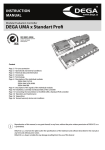
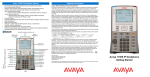
IP Phone 1200 Series User Guide
IP Phone 1200 Series
Business Communications Manager
Document Status: Standard
Document Version: 01.01
Document Number: NN40050-111
Date: August 2007
Copyright © Nortel Networks 2007, All rights reserved.
The information in this document is subject to change without notice. The statements, configurations, technical data, and
recommendations in this document are believed to be accurate and reliable, but are presented without express or implied
warranty. Users must take full responsibility for their applications of any products specified in this document. The
information in this document is proprietary to Nortel Networks.
Trademarks
Nortel, the Nortel logo, and the Globemark are trademarks of Nortel Networks.
Microsoft, MS, MS-DOS, Windows, and Windows NT are registered trademarks of Microsoft Corporation.
All other trademarks and registered trademarks are the property of their respective owners.
Contents
3
Contents
Regulatory and safety information. . . . . . . . . . . . . . . . . . . . . . . . . . . . . . . . . 5
How to get help . . . . . . . . . . . . . . . . . . . . . . . . . . . . . . . . . . . . . . . . . . . . . . . 11
Introduction . . . . . . . . . . . . . . . . . . . . . . . . . . . . . . . . . . . . . . . . . . . . . . . . . . 13
IP Phone 1210, 1220, and 1230 . . . . . . . . . . . . . . . . . . . . . . . . . . . . . . . . . . . . . . . . . 13
Basic features . . . . . . . . . . . . . . . . . . . . . . . . . . . . . . . . . . . . . . . . . . . . . . . . . . . . 13
Phone components . . . . . . . . . . . . . . . . . . . . . . . . . . . . . . . . . . . . . . . . . . . . . . . . 14
IP Phone 1210, 1220, and 1230 keys and descriptions . . . . . . . . . . . . . . . . . . . . 14
Display screen . . . . . . . . . . . . . . . . . . . . . . . . . . . . . . . . . . . . . . . . . . . . . . . . . . . 19
IP Phone 1200 series expansion modules . . . . . . . . . . . . . . . . . . . . . . . . . . . . . . . . . 20
Basic features . . . . . . . . . . . . . . . . . . . . . . . . . . . . . . . . . . . . . . . . . . . . . . . . . . . . 21
Expansion modules keys and descriptions . . . . . . . . . . . . . . . . . . . . . . . . . . . . . . 21
Configuring options. . . . . . . . . . . . . . . . . . . . . . . . . . . . . . . . . . . . . . . . . . . . 23
Local Tools menu . . . . . . . . . . . . . . . . . . . . . . . . . . . . . . . . . . . . . . . . . . . . . . . . . . . . 23
Using your IP Phone . . . . . . . . . . . . . . . . . . . . . . . . . . . . . . . . . . . . . . . . . . . 25
Ring type, call log, and time offset configuration . . . . . . . . . . . . . . . . . . . . . . . . . . . . . 25
Time offset . . . . . . . . . . . . . . . . . . . . . . . . . . . . . . . . . . . . . . . . . . . . . . . . . . . . . . 25
User-defined feature keys . . . . . . . . . . . . . . . . . . . . . . . . . . . . . . . . . . . . . . . . . . . . . . 26
Memory keys . . . . . . . . . . . . . . . . . . . . . . . . . . . . . . . . . . . . . . . . . . . . . . . . . . . . . 26
Call placement . . . . . . . . . . . . . . . . . . . . . . . . . . . . . . . . . . . . . . . . . . . . . . . . . . . . . . . 27
Call answer . . . . . . . . . . . . . . . . . . . . . . . . . . . . . . . . . . . . . . . . . . . . . . . . . . . . . . . . . 28
Call hold . . . . . . . . . . . . . . . . . . . . . . . . . . . . . . . . . . . . . . . . . . . . . . . . . . . . . . . . . . . 28
Handsfree . . . . . . . . . . . . . . . . . . . . . . . . . . . . . . . . . . . . . . . . . . . . . . . . . . . . . . . . . . 28
Headset . . . . . . . . . . . . . . . . . . . . . . . . . . . . . . . . . . . . . . . . . . . . . . . . . . . . . . . . . . . . 28
Mute key . . . . . . . . . . . . . . . . . . . . . . . . . . . . . . . . . . . . . . . . . . . . . . . . . . . . . . . . . . . 29
Applications key . . . . . . . . . . . . . . . . . . . . . . . . . . . . . . . . . . . . . . . . . . . . . . . . . . . . . 29
IP Phone 1200 Series User Guide
4
NN40050-111
Contents
5
Regulatory and safety information
This equipment has been tested and found to comply with the limits for a Class B digital device,
pursuant to part 15 of the FCC Rules. These limits are designed to provide reasonable protection
against harmful interference in a residential installation. This equipment generates, uses and can
radiate radio frequency energy and, if not installed and used in accordance with the instructions,
may cause harmful interference to radio communications. However, there is no guarantee that
interference will not occur in a particular installation. If this equipment does cause harmful
interference to radio or television reception, which can be determined by turning the equipment off
and on, the user is encouraged to try to correct the interference by one or more of the following
measures:
•
•
•
•
Reorient or relocate the receiving antenna.
Increase the separation between the equipment and receiver.
Connect the equipment into an outlet on a circuit different from that to which the receiver is
connected.
Consult the dealer or an experienced radio/ TV technician for help.
This Class B digital apparatus complies with Canadian ICES-003. Cet appareil numérique de la
classe B est conforme à la norme NMB-003 du Canada.
Warnings
•
•
This is a Class B product. In a domestic environment this product can cause radio interference
in which case the user must take adequate measures.
Operation is subject to the following two conditions: (1) this device may not cause
interference, and (2) this device must accept any interference, including interference that may
cause undesired operation of the device.”
この装置は、情報処理装置等電波障害自主規制協議会(VCCI)の基準に基づくクラス B 情報技術装置です。この装
置は、家庭環境で使用することを目的としていますが、この装置がラジオやテレビジョン受信機に近接して使用される
と、受信障害を引き起こすことがあります。
取扱説明書に従って正しい取り扱いをして下さい。
Table 1 lists EMC compliance for various jurisdictions.
Table 1 EMC compliance (Sheet 1 of 2)
Jurisdiction
Standard
United States
FCC CFR 47 Part 15 Class B Emissions: FCC Rules for Radio Frequency Devices
Canada
ICES-003
Australia/New Zealand CISPR 22
Description
Class B Emissions: Interference-Causing Equipment
Standard: Digital Apparatus
Class B Emissions: Information technology equipment Radio disturbance
IP Phone 1200 Series User Guide
6
Table 1 EMC compliance (Sheet 2 of 2)
Jurisdiction
Standard
Description
European Community
EN 55022
Class B Emissions: Information technology equipment Radio disturbance
EN 55024
Information technology equipment - Immunity characteristics
Limits and methods of measurement
EN 61000-3-2
Limits for harmonic current emissions (equipment input
current <= 16 A per phase)
EN 61000-3-3
Limitation of voltage fluctuations and flicker in low-voltage
supply systems for equipment with rated current <= 16 A
VCCI
Regulations for voluntary control measures.
Japan
Table 2 lists Safety compliance for various jurisdictions.
Table 2 Safety compliance
Jurisdiction
Standard
Description
United States
UL 60950-1
Safety of Information Technology Equipment
Canada
CSA 60950-1-03
Safety of Information Technology Equipment
European Community EN 60950-1
ITE equipment - Safety - Part 1: General requirements
Australia/New
Zealand
Safety of Information Technology Equipment
AS/NZS
60950.1:2003
Other Safety Approvals: IEC 60950-1: ITE equipment - Safety - Part 1: General requirements.
Other
US/Canada: Hearing Aid Compatibility (HAC) as per FCC Part 68
This equipment complies with the CE Marking requirements.
Australia: AS/ACIF S004: Voice Frequency Performance Requirements for Customer
Equipment
EU Countries: This device complies with the essential requirements and other relevant provisions
of Directive 1999/5/EC. A copy of the Declaration may be obtained from www.nortel.com or
Nortel Networks GmbH address: Ingolstaedter Strasse 14-18, 80807 Munich Germany
NN40050-111
7
DenAn regulatory notice for Japan
Connecting Power
Use Only with Nortel approved Limited Power Source 48Vdc 520mA (FSP Group Inc. Model:
FSP025-1AD207A)
Connecting to Local Area Network (LAN)
Severe damage to your IP Phone will occur if this set is plugged into an ISDN connection.
Consult your system administrator to ensure that you are plugging your set into a 10/100 Base-T
ethernet jack.
Operation
The earpiece / mouthpiece region on the handset can attract and retain small objects.
Location
It is recommended that this unit not be exposed to direct sunlight for a prolonged period of time.
IP Phone 1200 Series User Guide
8
NN40050-111
11
How to get help
This section explains how to get help for Nortel products and services.
Getting help from the Nortel Web site
The best way to get technical support for Nortel products is from the Nortel Technical Support
Web site:
www.nortel.com/support
This site provides quick access to software, documentation, bulletins, and tools to address issues
with Nortel products. More specifically, the site enables you to:
•
•
•
•
download software, documentation, and product bulletins
search the Technical Support Web site and the Nortel Knowledge Base for answers to
technical issues
sign up for automatic notification of new software and documentation for Nortel equipment
open and manage technical support cases
Getting help over the phone from a Nortel Solutions Center
If you do not find the information you require on the Nortel Technical Support Web site, and you
have a Nortel support contract, you can also get help over the phone from a Nortel Solutions
Center.
In North America, call 1-800-4NORTEL (1-800-466-7835).
Outside North America, go to the following Web site to obtain the phone number for your region:
www.nortel.com/callus
Getting help from a specialist by using an Express Routing Code
To access some Nortel Technical Solutions Centers, you can use an Express Routing Code (ERC)
to quickly route your call to a specialist in your Nortel product or service. To locate the ERC for
your product or service, go to:
www.nortel.com/erc
Getting help through a Nortel distributor or reseller
If you purchased a service contract for your Nortel product from a distributor or authorized
reseller, contact the technical support staff for that distributor or reseller.
IP Phone 1200 Series User Guide
12
NN40050-111
13
Chapter 1
Introduction
This section contains the following topics:
•
•
IP Phone 1210, 1220, and 1230 (page 13)
IP Phone 1200 series expansion modules (page 20)
IP Phone 1210, 1220, and 1230
The Nortel IP Phone 1210, 1220, and 1230 bring voice and data to the desktop by connecting
directly to a Local Area Network (LAN) through an Ethernet connection.
In this guide, programmable button labels appear beside the keys, and soft key labels appear
directly above the keys.
For information about telephone features and how to use them, see the Telephone Features User
Guide (NN40020-100).
Basic features
Your IP Phones support the following features:
•
•
•
•
•
•
•
•
•
•
•
four soft keys
specialized feature keys
six call processing fixed keys
— Mute
— Handsfree
— Goodbye
— Applications
— Headset
— Hold
volume control keys to adjust the ringer, speaker, handset, and headset volume
headset jack
handset jack
high-quality speaker phone
hearing aid compatibility
accessory expansion module (AEM) port
10/100 Ethernet ports
— one Ethernet port for LAN connection
— one Ethernet port for the optional PC connection
Power over Ethernet (PoE) or power through a supported AC adapter
IP Phone 1200 Series User Guide
14
Chapter 1
•
wall-mountable
In addition, the IP Phone 1220 and IP Phone 1230 models have the following features:
•
•
programmable keys with labels and indicators
specialized feature keys:
— Quit
— Directory
— Services
— Conferences
— Messages
— Redial
CAUTION
Risk of equipment damage
Do not plug the IP Phone 1210, 1220, or 1230 into a regular telephone
jack. This results in severe damage to the IP Phone. Consult your system
administrator to ensure that you plug your IP Phone into a 10/100 BaseT
Ethernet jack.
CAUTION
Risk of equipment damage
The IP Phone 1210, 1220, and 1230 are for use in an indoor environment
only.
Phone components
Your IP Phone 1210, 1220, and 1230 comes with
•
•
•
•
•
foot stand
handset
handset cord
2.1 m (7 ft) CAT5 Ethernet cable
number plate and lens
IP Phone 1210, 1220, and 1230 keys and descriptions
For the location of the keys and components on the IP Phone 1210, 1220, and 1230, see the
following figures. For a description of the keys and components on your IP Phone 1210, 1220,
and 1230, see the table IP Phone 1210, 1220, and 1230 keys and components descriptions
(page 18). Some keys or components are not available on all IP Phone models.
NN40050-111
Chapter 1
15
Figure 1 IP Phone 1210
Message waiting indicator/
Incoming call indicator
Display screen
Soft keys (4)
Programmable keys (2)
Navigation keys
Goodbye key
Applications key
Headset key
Hold key
Volume control keys
Mute key
Dialpad
Handsfree key
IP Phone 1200 Series User Guide
16
Chapter 1
Figure 2 IP Phone 1220
User-defined
feature keys (4)
Message waiting indicator/
Incoming call indicator
Display screen
Soft keys (4)
Programmable keys (6)
Navigation keys
Goodbye key
Applications key
Headset key
Hold key
Volume control keys
Mute key
Handsfree key
NN40050-111
Dialpad
Chapter 1
17
Figure 3 IP Phone 1230
User-defined
feature keys (10)
Message waiting indicator/
Incoming call indicator
Display screen
Soft keys (4)
Programmable keys (6)
Navigation keys
Goodbye key
Applications key
Headset key
Hold key
Volume control keys
Mute key
Dialpad
Handsfree key
IP Phone 1200 Series User Guide
18
Chapter 1
Table 3 IP Phone 1210, 1220, and 1230 keys and components descriptions (Sheet 1 of 2)
Key or component
Description
Message waiting indicator/
Incoming call indicator
When a message is waiting, the red message waiting indicator flashes.
Also, when the ringer sounds, this indicator flashes.
User-defined feature keys
(not available on the IP Phone
1210)
The keys on either side of the display area are programmable keys with
labels on the LCD display. The system administrator programs these
keys as either memory, line, or intercom keys.
A steady LCD light beside a programmable line (or intercom) key
indicates that the call is active. A flashing LCD light indicates that the
line or intercom call is on hold or that you have an incoming call.
For more information about the user-defined feature keys, see
User-defined feature keys (page 26).
Display screen
Shows the call information and phone status icons and guides you while
using features.
Soft keys
Soft keys are below the display area. The LCD label above each key
changes based on the active feature.
The Feature soft key is on the bottom left of the display area and is used
to access various phone options, such as changing the ring type
(Feature *6).
Programmable keys
The keys on either side of the navigation keys are programmable keys.
The IP Phone 1210 has two keys, while the IP Phone 1220 and 1230
have six keys. The system administrator programs these keys with the
following features:
Conference—access conferencing capabilities.
Quit—close an active menu or dialog box. Pressing the Quit key does
not affect the status of active calls.
Message—open your CallPilot mailbox. For more information about
mailbox options, see your CallPilot Quick Reference Card.
Redial—redial the last number called.
Directory—access speed call.
Services—access the scrollable Feature Display menu (FEATURE
*900) that includes
• Call Pickup
• Call Park
• Voice Call
• Page
• Background Music
• Message Send
• Hot Desking
• Call Forward
• Do Not Disturb
• Speed Call
• Last Number Redial
• Block Outgoing Name/Number
Double-press the Services key to access the Local Tools menu, and
use the navigation keys to make a selection. For details about the
Local Tools menu, see Local Tools menu options and descriptions
(page 23).
NN40050-111
Chapter 1
19
Table 3 IP Phone 1210, 1220, and 1230 keys and components descriptions (Sheet 2 of 2)
Key or component
Description
Navigation keys (with Enter
key)
Press the Navigation keys to scroll through menus and lists that appear
on the display screen. The outer part of this key cluster rocks for up,
down, left, and right movements.
Press the Enter key, at the center of the Navigation key cluster, to
confirm menu selections.
In most menus, you can press the Enter key instead of the Select soft
key.
Volume control keys
Press the Volume control keys to adjust the volume of the ringer,
handset, headset, speaker, and the Handsfree feature. Press the top
button to increase the volume, and press the bottom button to decrease
volume.
Mute key
Press the Mute key to listen to the receiving party without transmitting.
Press the Mute key again to return to two-way conversation. The Mute
LED indicator, on the Mute key, flashes to indicate that the microphone
is muted.
The Mute key applies to handsfree, handset, and headset microphones.
The microphone remains muted for your current call and all other calls
until you press the Mute key again to turn the microphone on.
Handsfree key
Press the Handsfree key to activate handsfree. The Handsfree LED
indicator, on the Handsfree key, lights to indicate when handsfree is
active.
Goodbye (Release) key
Press the Goodbye key to terminate an active call.
Applications key
Press the Applications key to access external server applications.
Headset key
Press the Headset key to answer a call using the headset or to switch a
call from the handset or handsfree to the headset. The Headset LED
indicator, on the Headset key, lights to indicate that the headset is in
use.
Hold key
Press the Hold key to put an active call on hold. Tap the flashing line
(DN) soft key to return to the caller on hold.
Display screen
Your IP Phone 1210, 1220, and 1230 have two or three display areas:
•
•
•
The top display area provides labels for the user-defined feature keys (not available on the
IP Phone 1210).
The middle display area contains two lines: a context line and an information line. The
context line displays the DN of the IP Phone. The information line displays items such as
caller number, caller name, feature prompt string, user-entered digits, date and time
information, and telephone information.
The bottom display area provides labels for the four soft keys.
The following figure shows an idle IP Phone 1230 display screen.
IP Phone 1200 Series User Guide
20
Chapter 1
Figure 4 IP Phone 1210, 1220, and 1230 display screen (IP Phone 1230 shown)
Top display area
User-defined feature
key labels (not available
on the IP Phone 1210)
Middle display area
Date and time display
Call party information
Feature status information
Options information
Directories information
Bottom display area
Soft keys (Feature key)
IP Phone 1200 series expansion modules
This section provides information about the LCD Expansion Module:12-Key Self-Labeling and
the LED Expansion Module:18-Key Paper Label.
The expansion modules are hardware accessories that connect to the IP Phone and provide
additional line appearances and feature keys. The following figure shows an IP Phone 1230
with the LCD Expansion Module:12-Key Self-Labeling.
Figure 5 IP Phone 1230 with LCD Expansion Module:12-Key Self-Labeling
NN40050-111
Chapter 1
21
Basic features
The expansion modules provide either 12 or 18 additional user-defined feature keys for your IP
Phone.
You can place the IP Phone and expansion modules on your desktop or you can wall-mount the
IP Phone and expansion modules.
An IP Phone supports up to seven LCD Expansion Module:12-Key Self-Labeling, or up to two
LED Expansion Module:18-Key Paper Label. One IP Phone does not support the two expansion
module types on the same IP Phone.
The following IP Phones support expansion modules:
•
•
IP Phone 1220
IP Phone 1230
Expansion modules keys and descriptions
For the location of the keys and components on the expansion modules, see the following
figures. For a description of the keys and components on your expansion modules, see the table
Expansion modules keys descriptions (page 22). Some keys or components are not available on
all expansion modules.
Figure 6 LCD Expansion Module:12-Key Self-Labeling
User-defined feature keys
Display (LCD)
IP Phone 1200 Series User Guide
22
Chapter 1
Figure 7 LED Expansion Module:18-Key Paper Label
User-defined feature key LEDs
User-defined feature keys
Labels
Table 4 Expansion modules keys descriptions
Key or component
Description
User-defined feature keys
The keys on the expansion modules are programmable keys with an
LCD display or paper labels. The system administrator programs these
keys as either memory, line, or intercom keys.
A steady LCD light beside a programmable line (or intercom) key
indicates that the call is active. A flashing LCD light indicates that the
line or intercom call is on hold or that you have an incoming call.
For more information about the user-defined feature keys, see
User-defined feature keys (page 26).
Display
The LCD display provides labels for the programmed keys and icons
that show the feature state.
User-defined feature key LEDs The LEDs show the feature state for the programmed keys.
Labels
NN40050-111
Create your own labels for each key.
23
Chapter 2
Configuring options
Many of the options discussed in this section are for system administrator use only. Do not make
changes unless you are instructed by your system administrator.
Local Tools menu
The Local Tools menu provides access to many configuration options. These settings also affect
the expansion modules on your IP Phones.
Two methods are available to navigate in the Local Tools menu:
•
•
Follow the prompts on the screen.
If a menu entry has a number in front of it, you can select that entry by pressing the associated
key on the dialpad. For example, when you are in the Local Tools menu, you can access 2.
Local Diagnostics by pressing the 2 key on the dialpad.
Accessing the Local Tools menu
1
Double-press
(Services) quickly to open the Local Tools menu.
If you attempt to access the Local Tools menu and a dialog box appears that prompts you for a
password, contact your system administrator.
2
From the Local Tools menu, press the key on the dialpad to open the chosen menu.
For more information about the menus and submenus, see the table Local Tools menu options
and descriptions (page 23).
3
From the selected menu, press the key on the dialpad to open the chosen submenu.
4
Use the navigation keys and Select key to make a selection.
5
Press the Cancel soft key to exit the menu or submenu.
Table 5 Local Tools menu options and descriptions
Main menu
Submenu
Description
1. Preferences
—
Use the Preferences menu to set or change preferences
for your IP Phone.
1. Contrast
Use the Contrast tool to change the physical settings of the
display.
2. Language
Use the Language tool to select the language used on your
phone.
IP Phone 1200 Series User Guide
24
Chapter 2
Table 5 Local Tools menu options and descriptions
Main menu
Submenu
Description
2. Local Diagnostics
--
Your system administrator uses the Local Diagnostics
menu to perform diagnostics on the IP Phone and network.
The Local Diagnostics menu is for system administrator
use only.
1. IPSet and DHCP Info
Use the IPSet and DHCP Info tool to view reports about IP
Phone and DHCP operation. This tool is for system
administrator use only.
2. Netwk Diagnostic Tools
The Network Diagnostic Tools menu contains tools to
diagnose network problems. This menu is for system
administrator use only.
3. Ethernet statistics
Use the Ethernet statistics tool view reports about Ethernet
operation. This menu is for system administrator use only.
4. IP Network statistics
Use the IP network statistics tool to view reports about
network operation. This menu is for system administrator
use only.
3. Network Configuration --
Use the Network Configuration tool to display configuration
information for your IP Phone. This tool is for system
administrator use only.
4. Lock Menu
The system administrator uses the Lock Menu tool to
protect the Local Tools menu items from accidental or
unwanted changes.
The Lock Menu tool is not available on all systems. If the
menu entry appears dimmed, it is not enabled on your
phone. Contact your system administrator to find out of this
feature is available for your use.
NN40050-111
--
25
Chapter 3
Using your IP Phone
This section provides information about the IP Phone 1210, 1220, and 1230, and expansion
modules settings, features, and functionality. For more information about telephone features, see
the Telephone Features User Guide.
Ring type, call log, and time offset configuration
Use the following procedures to configure your IP Phone 1210, 1220, and 1230.
Selecting the ring type
1
Press the Feature key, and then enter *6.
2
Press 1, 2, 3, 4, or Next to hear the various ring types.
3
Press OK to store the ring type.
Editing the call log
Your system administrator must enable call logs before you can edit them.
1
Press the Feature key, and then enter 812.
If call logs are not enabled, the display shows the message No log assigned.
2
Use the navigation keys to scroll through and edit the call log.
Time offset
When your IP Phone is in a time zone different from your system, the display shows the system
time instead of the local time. Use the Time Offset feature to adjust the time on the display. Before
you begin, calculate the time difference, in hours, between the server time and local time.
Changing the time offset
1
Press Feature *510.
2
Press Change.
3
Press * to switch between adding or subtracting time.
4
Using the dialpad, enter the number of hours between local time and system time.
Press # to enter half-hour increments.
5
Press OK.
It can take up to 1 minute for the change to appear on the display.
IP Phone 1200 Series User Guide
26
Chapter 3
User-defined feature keys
Your system administrator assigns the user-defined feature keys (on your IP Phone and
expansion module) as line, intercom, or memory keys. The label for each key appears on the
display next to the key. Your system administrator programs features on the line and intercom
keys. However, you can program certain features on the memory keys.
The user-defined feature keys are not available on the IP Phone 1210.
Memory keys
Your system administrator assigns the user-defined feature keys as memory keys. Memory keys
store phone numbers or features to give you one-touch dialing or feature activation.
Use the following procedures to program memory keys on your IP Phone 1210, 1220, and 1230
and expansion modules.
Programming external autodial
1
Press the Feature key, and then enter *1.
2
Press a memory key.
3
Using the dialpad, enter the external number.
4
Press OK to store the number.
The programmed phone number shows on the display.
Programming internal autodial
1
Press the Feature key, and then enter *2.
2
Press a memory key.
3
Using the dialpad, enter the extension number.
4
Press OK to store the extension number.
The name assigned to the number shows on the display with Ad to indicate AutoDial.
Programming a feature
1
Press the Feature key, and then enter *3.
2
Press a memory key.
3
Press the Feature key, and then enter the feature code.
4
Press OK to store the feature code.
NN40050-111
Chapter 3
27
Erasing memory keys
1
Press the Feature key, and then enter *1.
2
Press a memory key.
3
Press OK to erase the phone number or feature code programmed on the key.
Call placement
There are many ways to place a call depending on your telephone programming and call type.
Making a call
1
Lift the handset.
2
(optional) For external calls: Enter a line pool access code. For example, dial 9 or 6 for an
outside line.
3
Use the dialpad to dial the external number or the internal extension.
Making external calls using line keys
1
Lift the handset.
2
Press a line key.
3
Use the dialpad to dial the external number or the internal extension.
Making external calls using intercom keys
1
Lift the handset.
2
(optional) Press an intercom key, if required.
The BCM system selects an intercom key by default.
3
Enter a line pool access code. For example, dial 9 or 6 for an outside line.
4
When you hear an external dial tone, dial the external telephone number.
Contact your system administrator for a list of line pool codes.
Making internal calls using intercom keys
1
Lift the handset.
2
(optional) Press an intercom key, if required.
The BCM system selects an intercom key by default.
3
Dial the extension number.
Contact your system administrator for a list of extension numbers.
IP Phone 1200 Series User Guide
28
Chapter 3
Call answer
You have an incoming call when your telephone rings and the light flashes or when an intercom
or line soft key indicator flashes.
Answering a call
1
When you have an incoming call, perform one of the following:
•
•
Lift the handset.
Press the line or intercom key with the flashing S indicator, and then lift the handset.
Call hold
Calls are placed on hold automatically when you switch from one line to another.
Placing a call on hold
1
While a call is active, press
(Hold).
TheSindicator for the line on hold flashes.
2
To return to the call, press the line key with the flashing Sindicator.
Handsfree
To use the handsfree feature, perform one of the following tasks:
•
•
•
(Handsfree) to make or answer a call.
Press
To switch to handsfree when you are on a handset call, press
replace the handset. Lift the handset to switch back.
To switch to handsfree when you are on a headset call, press
Press
(Headset) to switch back.
(Handsfree) and
(Handsfree)
Headset
You must have a headset installed on your telephone to use this feature.To use your headset,
perform one of the following tasks:
•
•
•
Press
(Headset) to activate the headset mode. When the Headset LED indicator is
on, press a line or intercom soft key to make a call.
To switch to your headset when you are on a handset call, press
(Headset) and
replace the handset. Lift the handset to switch back.
To switch to your headset when you are on a Handsfree call, press
(Headset). Press
(Handsfree) to switch back.
NN40050-111
Chapter 3
29
Mute key
You can use mute (
•
•
•
) on handset, handsfree, or headset calls.
While you are on a call, press
(Mute) to turn off the microphone. The Mute LED
indicator flashes when the microphone is off.
Press
(Mute) again to turn on the microphone.
The microphone remains muted for your current call and all other calls until you press
(Mute) again to turn on the microphone.
Applications key
Use the Applications key to access a variety of applications directly from your IP Phone. To
find out which applications are available, contact your system administrator.
IP Phone 1200 Series User Guide