1
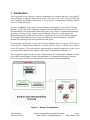
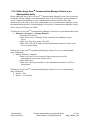
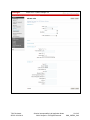
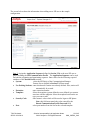
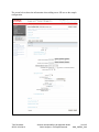
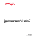
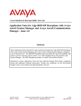
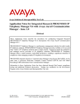
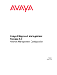
Avaya Solution Interoperability Test Lab Configuring Avaya 10x0 Series SIP Video Endpoints with Avaya AuraTM Session Manager Release 6.0 and Avaya AuraTM Communication Manager Feature Server Release 6.0 – Issue 1.0 Abstract These Application Notes describe the configuration of the Avaya 10x0 Series SIP Video Endpoints with Avaya AuraTM Session Manager and Avaya AuraTM Communication Manager as a Feature Server. Avaya AuraTM Session Manager provides SIP proxy/routing functionality, routing SIP sessions across a TCP/IP network with centralized routing policies and registrations for SIP endpoints. Avaya AuraTM Communication Manager operates as a Feature Server for the SIP endpoints which communicate with Avaya AuraTM Session Manager over SIP trunks. These Application Notes provide information for the setup, configuration, and verification of the call flows tested on this solution. TJM Reviewed: SPOC 12/01/2010 Solution Interoperability Lab Application Notes ©2010 Avaya Inc. All Rights Reserved. 1 of 45 SM6_CMFS6_10x0 Table of Contents: 1. Introduction ............................................................................................................. 4 1.1. Equipment and Software Validated......................................................................... 5 2. Configuring Avaya AuraTM Communication Manager Feature Server ..................... 5 2.1. Verify System Capabilities and Licensing ............................................................... 5 2.1.1. SIP Trunk Capacity Check ................................................................................. 6 2.1.2. AAR/ARS Routing Check ................................................................................... 6 2.1.3. Enable Private Numbering.................................................................................. 7 2.2. Add Node Name of Avaya AuraTM Session Manager ............................................. 7 2.3. Configure Codec Type ............................................................................................ 8 2.4. Configure IP Network Region ................................................................................. 8 2.5. Add SIP Signaling Group ........................................................................................ 9 2.6. Add SIP Trunk Group ........................................................................................... 10 2.7. Administering Numbering Plan ............................................................................. 11 2.8. Configure Stations ................................................................................................ 12 2.9. Configure Off-PBX-Telephone Station-Mapping ................................................... 14 2.10. Save Translations ................................................................................................. 14 3. Configure Avaya Aura™ Session Manager .......................................................... 14 3.1. Administer SIP Domains ....................................................................................... 15 3.2. Define Locations ................................................................................................... 16 3.3. Add Avaya AuraTM Communication Manager Feature Server............................... 17 3.3.1. Define a SIP Element for Avaya AuraTM Communication Manager Feature Server ............................................................................................................... 17 3.3.2. Define Element Link for Avaya AuraTM Communication Manager Feature Server ......................................................................................................................... 18 3.3.3. Define Routing Policy for Avaya AuraTM Communication Manager Feature Server ............................................................................................................... 18 3.3.4. Define Applications for Avaya AuraTM Communication Manager Feature Server ......................................................................................................................... 19 3.3.5. Define Application Sequences for Avaya AuraTM Communication Manager Feature Server ................................................................................................. 20 3.3.6. Define Avaya AuraTM Communication Manager Feature as an Administrable Entity ................................................................................................................ 21 3.3.7. Add SIP Users .................................................................................................. 23 4. Configure Avaya 10x0 Video Endpoint ................................................................. 27 5. Verification Steps .................................................................................................. 34 TJM Reviewed: SPOC 12/01/2010 Solution Interoperability Lab Application Notes ©2010 Avaya Inc. All Rights Reserved. 2 of 45 SM6_CMFS6_10x0 5.1. Verify Avaya AuraTM Session Manager Configuration ........................................... 34 5.1.1. Verify Avaya AuraTM Session Manager is Operational ..................................... 34 5.1.2. Verify SIP Link Status ....................................................................................... 36 5.1.3. Verify Registrations of SIP Endpoints ............................................................... 37 5.2. Verify Avaya AuraTM Communication Manager Feature Server Configuration...... 39 5.3. Call Scenarios Verified ......................................................................................... 42 6. Acronyms .............................................................................................................. 43 7. Conclusion ............................................................................................................ 43 8. Additional References........................................................................................... 43 TJM Reviewed: SPOC 12/01/2010 Solution Interoperability Lab Application Notes ©2010 Avaya Inc. All Rights Reserved. 3 of 45 SM6_CMFS6_10x0 1. Introduction These Application Notes present a sample configuration for a network that uses Avaya Aura™ Session Manager to support registration of Avaya 10x0 (1010, 1020, 1030, 1040, and 1050) SIP Video endpoints and enables connectivity to Avaya Aura™ Communication Manager Feature Server 6.0 using SIP trunks. As shown in Figure 1, Avaya Aura™ Session Manager is managed by Avaya Aura™ System Manager. Avaya 10x0 Video Endpoints configured as SIP endpoints utilize the Avaya Aura™ Session Manager User Registration feature and require Avaya Aura™ Communication Manager operating as a Feature Server. Communication Manager Feature Server only supports IP Multimedia Subsystem (IMS)-SIP users that are registered to Avaya Aura™ Session Manager. The Communication Manager Feature Server is connected to Session Manager via an IMSenabled SIP signaling group and associated SIP trunk group. For the sample configuration, Avaya Aura™ Session Manager runs on an Avaya S8510 Server. Avaya Aura™ Communication Manager 6.0 Feature Server runs on a S8800 server with an Avaya 450 Gateway. The results in these Application Notes should be applicable to other Avaya servers and media gateways that support Avaya Aura™ Communication Manager 6.0. These Application Notes will focus on the configuration of the Communication Manager Feature Server and Session Manager. Detailed administration of Communication Manager Evolution Server will not be described (see the appropriate documentation listed in Section 8). Figure 1 – Sample Configuration TJM Reviewed: SPOC 12/01/2010 Solution Interoperability Lab Application Notes ©2010 Avaya Inc. All Rights Reserved. 4 of 45 SM6_CMFS6_10x0 1.1. Equipment and Software Validated The following equipment and software were used for the sample configuration. Equipment Avaya AuraTM Session Manager Avaya AuraTM System Manager Avaya AuraTM Communication Manager • Avaya S8800 Server Feature Server Avaya IP Telephones10x0 Video Endpoints (SIP): • 1020 • 1030 • 1040 Software Release 6.0.0.0.600020 Release 6.0 Load: 6.0.0.0.11 Release R016x.00.0.345.0-2350 FW: AV_PP1_4.7.0 (19)2.0 FW:3.0 AV_EX2_4.7.0 (19) FW:1.5 AV_TM2_4.7.0 (19) 2. Configuring Avaya AuraTM Communication Manager Feature Server This section describes the administration of Communication Manager Feature Server using a System Access Terminal (SAT). Alternatively, some of the station administration could be performed using the Communication System Management application on System Manager. These instructions assume the G450 Media Gateway is already configured on the Communication Manager Feature Server. Some administration screens have been abbreviated for clarity. Verify System Capabilities and Communication Manager Licensing Administer IP node names Administer codec type Administer IP network region Administer SIP signaling group Administer SIP trunk group Administer numbering plan Administer station endpoints Administer off-pbx-telephone station-mapping Save translations After completing these steps, the “save translation” command should be performed. 2.1. Verify System Capabilities and Licensing This section describes the procedures to verify the correct system capabilities and licensing have been configured. If there is insufficient capacity or a required feature is not available, contact an authorized Avaya sales representative to make the appropriate changes. TJM Reviewed: SPOC 12/01/2010 Solution Interoperability Lab Application Notes ©2010 Avaya Inc. All Rights Reserved. 5 of 45 SM6_CMFS6_10x0 2.1.1. SIP Trunk Capacity Check Issue the display system-parameters customer-options command to verify that an adequate number of SIP trunk members are licensed for the system as shown below: display system-parameters customer-options OPTIONAL FEATURES Page IP PORT CAPACITIES Maximum Administered H.323 Trunks: Maximum Concurrently Registered IP Stations: Maximum Administered Remote Office Trunks: Maximum Concurrently Registered Remote Office Stations: Maximum Concurrently Registered IP eCons: Max Concur Registered Unauthenticated H.323 Stations: Maximum Video Capable Stations: Maximum Video Capable IP Softphones: Maximum Administered SIP Trunks: Maximum Administered Ad-hoc Video Conferencing Ports: Maximum Number of DS1 Boards with Echo Cancellation: Maximum TN2501 VAL Boards: Maximum Media Gateway VAL Sources: Maximum TN2602 Boards with 80 VoIP Channels: Maximum TN2602 Boards with 320 VoIP Channels: Maximum Number of Expanded Meet-me Conference Ports: 12000 18000 12000 18000 414 100 18000 18000 24000 24000 522 128 250 128 128 300 2 of 11 USED 0 0 0 0 0 0 0 0 128 50 0 0 0 0 0 0 (NOTE: You must logoff & login to effect the permission changes.) 2.1.2. AAR/ARS Routing Check Verify that ARS is enabled (on page 3 of system-parameters customer options) display system-parameters customer-options OPTIONAL FEATURES A/D Grp/Sys List Dialing Start at 01? Answer Supervision by Call Classifier? ARS? ARS/AAR Partitioning? ARS/AAR Dialing without FAC? ASAI Link Core Capabilities? TJM Reviewed: SPOC 12/01/2010 n n y y y y Page 3 of 11 CAS Main? Change COR by FAC? Computer Telephony Adjunct Links? Cvg Of Calls Redirected Off-net? DCS (Basic)? DCS Call Coverage? Solution Interoperability Lab Application Notes ©2010 Avaya Inc. All Rights Reserved. n n y y y 6 of 45 SM6_CMFS6_10x0 2.1.3. Enable Private Numbering Use the “change system-parameters customer-options” command to verify that Private Networking is enabled as shown below: display system-parameters customer-options OPTIONAL FEATURES Multinational Locations? y Multiple Level Precedence & Preemption? n Multiple Locations? y Personal Station Access (PSA)? PNC Duplication? Port Network Support? Posted Messages? y n n n Private Networking? y Processor and System MSP? y Processor Ethernet? y 2.2. Page 5 of 11 Station and Trunk MSP? y Station as Virtual Extension? y System Management Data Transfer? Tenant Partitioning? Terminal Trans. Init. (TTI)? Time of Day Routing? TN2501 VAL Maximum Capacity? Uniform Dialing Plan? Usage Allocation Enhancements? n n y n y y y Wideband Switching? n Wireless? y Add Node Name of Avaya AuraTM Session Manager Using the change node-names ip command, add the node-name and IP for the Session Manager’s software asset, if not previously added. change node-names ip Page 1 of 2 IP NODE NAMES Name default procr procr6 silasm4 TJM Reviewed: SPOC 12/01/2010 IP Address 0.0.0.0 135.9.88.72 :: 135.9.88.62 Solution Interoperability Lab Application Notes ©2010 Avaya Inc. All Rights Reserved. 7 of 45 SM6_CMFS6_10x0 2.3. Configure Codec Type Issue the change ip-codec-set n command where “n” is the next available number. Enter the following values: Enter “G.711MU” and “G.729” as supported types of Audio Codecs Silence Suppression: Retain the default value “n”. Frames Per Pkt: Enter “2”. Packet Size (ms): Enter “20”. Media Encryption: Enter the value based on the system requirement. For the sample configuration “none” was used. change ip-codec-set 1 Page 1 of 2 IP Codec Set Codec Set: 1 Audio Codec 1: G.711MU 2: G.729 3: Silence Suppression n n Frames Per Pkt 2 2 Packet Size(ms) 20 20 Media Encryption 1: none 2.4. Configure IP Network Region Using the change ip-network-region 1 command, set the Authoritative Domain. For the sample configuration “dr.avaya.com” was used. Verify the Intra-region IP-IP Direct Audio, and Inter-region IP-IP Direct Audio fields are set to yes. change ip-network-region 1 Page 1 of 19 IP NETWORK REGION Region: 1 Location: 1 Authoritative Domain: dr.avaya.com Name: CMFS-Video MEDIA PARAMETERS Intra-region IP-IP Direct Audio: yes Codec Set: 1 Inter-region IP-IP Direct Audio: yes UDP Port Min: 2048 IP Audio Hairpinning? n UDP Port Max: 16585 TJM Reviewed: SPOC 12/01/2010 Solution Interoperability Lab Application Notes ©2010 Avaya Inc. All Rights Reserved. 8 of 45 SM6_CMFS6_10x0 2.5. Add SIP Signaling Group Issue the add signaling-group n command, where “n” is an available signaling group number, for one of the SIP trunks to the Session Manager, and fill in the indicated fields. In the sample configuration, trunk group “1” and signaling group “1” were used to connect to Avaya Aura™ Session Manager. Default values can be used for the remaining fields. Group Type: Transport Method: IMS Enabled?: IP Video?: Peer Detection Enabled?: Peer Server: Near-end Node Name: Far-end Node Name: Near-end Listen Port: Far-end Listen Port: Far-end Domain: Enable Layer 3 Test: Direct IP-IP Early Media?: “sip” ”tcp” “y” “y” “y” Use default value. Note: default value is replaced with “SM” after SIP trunk to Session Manager is established procr from Section 2.2 Session Manager node name from Section 2.2 “5060” “5060” Authoritative Domain from Section 2.4 “y” “y” display signaling-group 1 Page 1 of 1 SIGNALING GROUP Group Number: 1 Group Type: sip Transport Method: tcp IMS Enabled? y IP Video? y Priority Video? y Peer Detection Enabled? y Peer Server: SM Near-end Node Name: procr Near-end Listen Port: 5060 Far-end Node Name: silasm4 Far-end Listen Port: 5060 Far-end Network Region: 1 Far-end Domain: dr.avaya.com Incoming Dialog Loopbacks: eliminate DTMF over IP: rtp-payload Session Establishment Timer(min): 3 Enable Layer 3 Test? y H.323 Station Outgoing Direct Media? n TJM Reviewed: SPOC 12/01/2010 Bypass If IP Threshold Exceeded? n RFC 3389 Comfort Noise? n Direct IP-IP Audio Connections? y IP Audio Hairpinning? n Direct IP-IP Early Media? y Alternate Route Timer(sec): 6 Solution Interoperability Lab Application Notes ©2010 Avaya Inc. All Rights Reserved. 9 of 45 SM6_CMFS6_10x0 2.6. Add SIP Trunk Group Add the corresponding trunk group controlled by this signaling group via the add trunk-group n command, where “n” is an available trunk group number and fill in the indicated fields. Group Type: Group Name: TAC: Service Type: Signaling Group: Number of Members: “sip” A descriptive name. An available trunk access code. “tie” The number of the signaling group added in Section 2.5 The number of SIP trunks to be allocated to calls routed to Session Manager (must be within the limits of the total number of trunks configured in Section 2.1.1). add trunk-group 1 Page 1 of 21 TRUNK GROUP Group Number: 1 Group Type: sip CDR Reports: y Group Name: SIP Video TG to silasm4 COR: 1 TN: 1 TAC: #001 Direction: two-way Outgoing Display? y Dial Access? n Night Service: Queue Length: 0 Service Type: tie Auth Code? n Signaling Group: 1 Number of Members: 64 Once the add command is completed, trunk members will be automatically generated based on the value in the Number of Members field. On Page 2, set the Preferred Minimum Session Refresh Interval to 1200. Note: to avoid extra SIP messages, all SIP trunks connected to Session Manager should be configured with a minimum value of 1200. add trunk-group 1 Page 2 of 21 Group Type: sip TRUNK PARAMETERS Unicode Name: auto Redirect On OPTIM Failure: 5000 SCCAN? n TJM Reviewed: SPOC 12/01/2010 Digital Loss Group: 18 Preferred Minimum Session Refresh Interval(sec): 1200 Solution Interoperability Lab Application Notes ©2010 Avaya Inc. All Rights Reserved. 10 of 45 SM6_CMFS6_10x0 On Page 3, set Numbering Format to be “private”. Use default values for all other fields. add trunk-group 1 TRUNK FEATURES ACA Assignment? n Page 3 of 21 Measured: none Maintenance Tests? y Numbering Format: private UUI Treatment: service-provider Replace Restricted Numbers? n Replace Unavailable Numbers? n 2.7. Administering Numbering Plan SIP Users registered to Session Manager needs to be added to either the private or public numbering table on the Communication Manager Feature Server. For the sample configuration, private numbering was used and all extension numbers were unique within the private network. However, in many customer networks, it may not be possible to define unique extension numbers for all users within the private network. For these types of networks, additional administration may be required as described in References [3] and [8] in Section 8. To enable SIP endpoints to dial extensions defined in the Communication Manager Feature Server, use the “change private-numbering x” command, where x is the number used to identify the private number plan. For the sample configuration, extension numbers starting with 5-XXXX are used on the Communication Manager Feature Server. Ext Len: Ext Code: Trunk Grp: Enter the extension length allowed by the dial plan Enter leading digit (s) from extension number Enter the SIP Trunk Group number for the SIP trunk between the Feature Server and Session Manager Leave blank unless an enterprise canonical numbering scheme is defined in Session Manager. If so, enter the appropriate prefix. Private Prefix: change private-numbering 1 Page 1 of 2 NUMBERING - PRIVATE FORMAT Ext Ext Len Code 5 5 TJM Reviewed: SPOC 12/01/2010 Trk Grp(s) 1 Private Prefix Total Len 5 Total Administered: 1 Maximum Entries: 540 Solution Interoperability Lab Application Notes ©2010 Avaya Inc. All Rights Reserved. 11 of 45 SM6_CMFS6_10x0 2.8. Configure Stations The method is the same for administering all of the Avaya 1000 series video endpoints with the exception of the 1040 and 1050’s. The only difference is that the 1040 can be administered to have up to 3 call appearances and the 1050 can have up to 7 call appearances for conferencing via their internal MCU’s. The 1010, 1020, and 1030 have to be administered with only one callappearance since they are a single-line endpoint with no conferencing or transferring capabilities. For each SIP user to be defined in Session Manager, add a corresponding station on the Communication Manager Feature Server. Note: instead of manually defining each station using the Communication Manager SAT interface, the preferred option is to automatically generate the SIP station when adding a new SIP user. See Section 3.3.6 for more information on adding SIP users. The phone number defined for the station will be the number the SIP user enters to register to Session Manager. Use the “add station x” command where x is a valid extension number defined in the system. In this example extension 55002 is an Avaya 1020 video endpoint. On page 1 of the change station form: Phone Type: Name: Security Code: IP Video? Set to 9630SIP Display name for user Number used when user logs into station. Note: this code should match the “Shared Communication Profile Password” field defined when adding this user in Session Manager. See Section 3.3.6. Enable endpoint for video add station 55002 Page 1 of 6 STATION Extension: Type: Port: Name: 55002 9630SIP S00006 SIL Video Lab - 1020 Lock Messages? n Security Code: 123456 Coverage Path 1: 1 Coverage Path 2: Hunt-to Station: BCC: TN: COR: COS: 0 1 1 1 STATION OPTIONS Time of Day Lock Table: Loss Group: 19 Display Language: english Survivable COR: internal Survivable Trunk Dest? y Message Lamp Ext: 55002 Button Modules: 0 IP SoftPhone? n IP Video? y TJM Reviewed: SPOC 12/01/2010 Solution Interoperability Lab Application Notes ©2010 Avaya Inc. All Rights Reserved. 12 of 45 SM6_CMFS6_10x0 Note: It is important to assign only one call-appearance for the 1010, 1020, and 1030’s. add station 55002 Page 4 of 6 STATION SITE DATA Room: Jack: Cable: Floor: Building: ABBREVIATED DIALING List1: Headset? Speaker? Mounting: Cord Length: Set Color: List2: BUTTON ASSIGNMENTS 1: call-appr 2: 3: 4: n n d 0 List3: 5: 6: 7: 8: On page 6, set: SIP Trunk option: Enter SIP Trunk Group defined in Section 2.6 change station 55002 Page 6 of 6 STATION SIP FEATURE OPTIONS Type of 3PCC Enabled: None SIP Trunk: 1 TJM Reviewed: SPOC 12/01/2010 Solution Interoperability Lab Application Notes ©2010 Avaya Inc. All Rights Reserved. 13 of 45 SM6_CMFS6_10x0 2.9. Configure Off-PBX-Telephone Station-Mapping Use the “change off-pbx-telephone station-mapping” command for each extension associated with SIP users defined in Session Manager. On page 1, enter the SIP Trunk Group defined in Section 2.6 and use default values for other fields. change off-pbx-telephone station-mapping 55002 Page 1 of 3 STATIONS WITH OFF-PBX TELEPHONE INTEGRATION Station Extension 55002 Application Dial CC Prefix OPS - Phone Number 55002 Trunk Selection 1 Config Set 1 Dual Mode On Page 2, enter the following values: Mapping Mode: “both” Calls Allowed: “all” change off-pbx-telephone station-mapping 55002 Page 2 of 3 STATIONS WITH OFF-PBX TELEPHONE INTEGRATION Station Extension 55002 Appl Name OPS Call Limit 1 Mapping Mode both Calls Allowed all Bridged Calls none Location - 2.10. Save Translations Configuration of Communication Manager Feature Server is complete. Use the “save translations” command to save these changes Note: After a change on Communication Manager Feature Server which alters the dial plan, synchronization between Communication Manager Feature Server and Session Manager needs to be completed and SIP phones must be re-registered. To request an on demand synchronization, log into the System Manager console and use the Synchronize CM Data feature under the Communication System Management menu. 3. Configure Avaya Aura™ Session Manager This section provides the procedures for configuring the Session Manager and includes the following items: Administer SIP domain Define Logical/Physical Locations that can be occupied by SIP Entities TJM Reviewed: SPOC 12/01/2010 Solution Interoperability Lab Application Notes ©2010 Avaya Inc. All Rights Reserved. 14 of 45 SM6_CMFS6_10x0 For each SIP entity in the sample configuration: o Define SIP Entity o Define Entity Links, which define the SIP trunk parameters used by Avaya Aura ™ Session Manager when routing calls to/from SIP Entities o Define Routing Policies, which control call routing between the SIP Entities o Define Dial Patterns, which govern to which SIP Entity a call is routed Define the Communication Manager Feature Server as an Managed Element Adding SIP Endpoints/SIP URE users Configuration is accomplished by accessing the browser-based GUI of Avaya Aura™ System Manager, using the URL “http://<ip-address>/SMGR”, where “<ip-address>” is the IP address of Avaya Aura™ System Manager. Log in with the appropriate credentials and accept the Copyright Notice. Expand the Routing Link on the left side of Navigation Menu. Select a specific item such as Domains. 3.1. Administer SIP Domains Expand Routing and select Domains. Click New In the General Section, under Name add a descriptive name. Under Notes add a brief description. Click Commit to save. The screen below shows the information for the sample configuration. TJM Reviewed: SPOC 12/01/2010 Solution Interoperability Lab Application Notes ©2010 Avaya Inc. All Rights Reserved. 15 of 45 SM6_CMFS6_10x0 3.2. Define Locations Expand Routing and select Locations. Locations are used to identify logical and/or physical locations where SIP Entities reside, for purposes of bandwidth management or location-based routing. Click New In the General Section, under Name add a descriptive name. Under Notes add a brief description. In the Location Pattern Section, under IP Address Pattern enter pattern used to logically identify the location Under Notes add a brief description. Click Commit to save. The screen below shows the information for Communication Manager Feature Server in the sample configuration. TJM Reviewed: SPOC 12/01/2010 Solution Interoperability Lab Application Notes ©2010 Avaya Inc. All Rights Reserved. 16 of 45 SM6_CMFS6_10x0 3.3. Add Avaya AuraTM Communication Manager Feature Server The following section captures relevant screens for defining Avaya AuraTM Communication Manager Feature Server applicable for the sample configuration. 3.3.1. Define a SIP Element for Avaya AuraTM Communication Manager Feature Server The following screen shows addition of Communication Manager Feature Server. The IP address used is that of the Processor Ethernet (procr) of the Avaya Communication Manager Feature server. TJM Reviewed: SPOC 12/01/2010 Solution Interoperability Lab Application Notes ©2010 Avaya Inc. All Rights Reserved. 17 of 45 SM6_CMFS6_10x0 3.3.2. Define Element Link for Avaya AuraTM Communication Manager Feature Server The following screen shows the Element Link defined for the Avaya AuraTM Communication Manager Feature Server. 3.3.3. Define Routing Policy for Avaya AuraTM Communication Manager Feature Server Since the SIP users are registered on Session Manager, a routing policy does not need to be defined for the Communication Manager Feature Server. TJM Reviewed: SPOC 12/01/2010 Solution Interoperability Lab Application Notes ©2010 Avaya Inc. All Rights Reserved. 18 of 45 SM6_CMFS6_10x0 3.3.4. Define Applications for Avaya AuraTM Communication Manager Feature Server To define the Avaya AuraTM Communication Manager Feature Server Applications, Elements -> Session Manager, Application Configuration Applications o Click New (Not shown) o Under Name, enter a name for the Application entry o Under SIP Entity drop-down menu, select the appropriate SIP Entity. o Under CM System for SIP Entity, this field can be left as the default of Select CM System. o Under Description, enter a description if desired. o Click Commit to save. TJM Reviewed: SPOC 12/01/2010 Solution Interoperability Lab Application Notes ©2010 Avaya Inc. All Rights Reserved. 19 of 45 SM6_CMFS6_10x0 3.3.5. Define Application Sequences for Avaya AuraTM Communication Manager Feature Server To define the Avaya AuraTM Communication Manager Feature Server Application Sequences, Elements -> Session Manager, Application Configuration Application Sequences o Click New (Not shown) o Under Name, enter a name of the Application Sequence. o Under Description, enter a description if desired. o Under Available Applications, select the Application that was created in Section 3.3.4. The way to select the Application of choice is to click on the “+” symbol next to the Application desired. This will be added to the Applications in this Sequence list. o Click Commit to save. Second, define an Application Sequence for call application sequencing in the Avaya AuraTM Communication Manager Feature Server as shown below: TJM Reviewed: SPOC 12/01/2010 Solution Interoperability Lab Application Notes ©2010 Avaya Inc. All Rights Reserved. 20 of 45 SM6_CMFS6_10x0 3.3.6. Define Avaya AuraTM Communication Manager Feature as an Administrable Entity Before adding SIP users, the Avaya AuraTM Communication Manager Feature Server must also be added to System Manager as an administrable entity. This action allows System Manager to access Communication Manager over its administration interface similar to how other administration tools such as Avaya Site Administrator access Communication Manager. Using this administration interface, System Manager will notify the Communication Manager Feature Server when new SIP users are added. To define the Avaya AuraTM Communication Manager Feature Server as an administrable entity, Elements -> Inventory -> Manage Elements o Click New (Not shown) o Under Name, enter an identifier for the Communication Manager Feature Server. o Under Type drop-down menu, select CM. o Under Node, enter the IP address of the administration interface for the Feature Server as shown below: Defining the Avaya AuraTM Communication Manager Feature Server as an administrable entity (continued): Manage Elements - Attributes o Under Login and Password, enter the login and password used for administration access to the Feature Server. o Select SSH access. o Under Port, enter the port number for the administration interface of 5022 as shown below: Defining the Avaya AuraTM Communication Manager Feature Server as an administrable entity (continued): Entities – Port Entities – Access Point TJM Reviewed: SPOC 12/01/2010 Solution Interoperability Lab Application Notes ©2010 Avaya Inc. All Rights Reserved. 21 of 45 SM6_CMFS6_10x0 TJM Reviewed: SPOC 12/01/2010 Solution Interoperability Lab Application Notes ©2010 Avaya Inc. All Rights Reserved. 22 of 45 SM6_CMFS6_10x0 3.3.7. Add SIP Users Add SIP users corresponding to the 96XX SIP stations defined in Section 2.8. Alternatively, use the option to automatically generate the SIP stations on Communication Manager Feature Server when adding a new SIP user. Expand Users o Select Manage Users Click New Step 1: Enter values for the following required attributes for a new SIP user in the General and Identity sections of the new user form. Last Name: enter last name of user First Name: enter first name of user Login Name: enter extension no.@sip domain defined in Section 3.1. This field is primary handle of user. Authentication Type: select Basic SMGR Login Password: enter password which will be used to log into System Manager application (password). NOTE: This field is only displayed if adding a new user. Confirm Password: repeat value entered above. NOTE: This field is only displayed if adding a new user. Shared Communication Profile Password: enter a numeric value which will be used to logon to SIP phone. Note: this field must match the Security Code field on the station form defined in Section 2.8. Confirm Password: repeat numeric password The screen below shows the information when adding a new SIP user to the sample configuration. TJM Reviewed: SPOC 12/01/2010 Solution Interoperability Lab Application Notes ©2010 Avaya Inc. All Rights Reserved. 23 of 45 SM6_CMFS6_10x0 Step 2: Scroll down to the Communication Profile section and Select New to define a Communication Profile for the new SIP user. Enter values for the following required attributes: Name: enter name of communication profile Default: enter checkmark to indicate this profile is default profile Select New to define a Communication Address for the new SIP user. Enter values for the following required attributes: Type: select SIP Handle: enter extension number Domain: enter SIP domain defined in Section 3.1 Click Add (not shown) to save the Communication Address for the new SIP user. TJM Reviewed: SPOC 12/01/2010 Solution Interoperability Lab Application Notes ©2010 Avaya Inc. All Rights Reserved. 24 of 45 SM6_CMFS6_10x0 The screen below shows the information when adding a new SIP user to the sample configuration. Step 3: Assign the Application Sequence defined in Section 3.3.4 to the new SIP user as part of defining the SIP Communication Profile. The Application Sequence can be used for both the originating and terminating sequence. Enter values for the following required attributes of the Station Profile section: System: select the SIP Entity of the Communication Manager Feature Server defined in Section 3.3.5 from menu Use Existing Stations: enter checkmark if station was already defined. Else, station will automatically be created. Extension: enter extension number Template: Select the template (system defined or user defined) you want to associate with the endpoint. Select the template based on the set type you want to add. Security Code: enter numeric value which will be used to logon to SIP phone. Note: this field must match the value entered for the Shared Communication Profile Password field Port: select port number from the list for the selected template TJM Reviewed: SPOC 12/01/2010 Solution Interoperability Lab Application Notes ©2010 Avaya Inc. All Rights Reserved. 25 of 45 SM6_CMFS6_10x0 The screen below shows the information when adding a new SIP user to the sample configuration. TJM Reviewed: SPOC 12/01/2010 Solution Interoperability Lab Application Notes ©2010 Avaya Inc. All Rights Reserved. 26 of 45 SM6_CMFS6_10x0 4. Configure Avaya 10x0 Video Endpoint To administer the 10x0 video endpoints log in to the web interface using the IP address of the video endpoint. You will be redirected to a screen that looks similar to the one below. This is a sample configuration on how to administer a 10x0 video endpoint. Step 1: Enter the proper login credentials and press Submit. Most of the Preferences can be customized to meet your needs. Mentioned below are the absolute necessary items that need to be administered to get the 10x0 up and running on the network. TJM Reviewed: SPOC 12/01/2010 Solution Interoperability Lab Application Notes ©2010 Avaya Inc. All Rights Reserved. 27 of 45 SM6_CMFS6_10x0 Once logged in select the Preferences tab and then the Network option. TJM Reviewed: SPOC 12/01/2010 Solution Interoperability Lab Application Notes ©2010 Avaya Inc. All Rights Reserved. 28 of 45 SM6_CMFS6_10x0 Select General option and enter values for the following required attributes. DHCP: IP Address: Subnet Mask: Default Gateway: Hostname: DNS Servers: NTP Server Hostname: enabled/disabled enter IP Address if DHCP is disabled enter Subnet Mask if DHCP is disabled enter Default Gateway if DHCP is disabled enter the appropriate Hostname enter the appropriate DNS Servers enter NTP Server Hostname Select the Save Changes button to save the administration just added. TJM Reviewed: SPOC 12/01/2010 Solution Interoperability Lab Application Notes ©2010 Avaya Inc. All Rights Reserved. 29 of 45 SM6_CMFS6_10x0 Select the Preferences option and select the Communications option. TJM Reviewed: SPOC 12/01/2010 Solution Interoperability Lab Application Notes ©2010 Avaya Inc. All Rights Reserved. 30 of 45 SM6_CMFS6_10x0 Select the SIP option. SIP: SIP Username: enabled enter the SIP Username for the device. NOTE: The SIP Username should be unique and meaningful to the endpoint. Authorization Name: enter the SIP Server authorization username. NOTE: The Authorization Name should be unique and meaningful to the endpoint. Authorization Password: enter the SIP Server authorization password SIP Registration: select the communication path to use when registering with a SIP Registrar SIP Proxy: choose ‘Enabled’ to use the SIP proxy Proxy Hostname: enter the hostname or IP address of the SIP proxy server. NOTE: This is the Session Manager software asset card IP address Proxy IP Port: enter the IP port number of SIP proxy server SIP Registrar: choose ‘Enabled’ to use the SIP registrar Registrar Hostname: enter the hostname or IP address of the SIP registrar server TJM Reviewed: SPOC 12/01/2010 Solution Interoperability Lab Application Notes ©2010 Avaya Inc. All Rights Reserved. 31 of 45 SM6_CMFS6_10x0 Registrar IP Port: UDP Signaling Port: TCP Signaling: TCP signaling Port: enter the IP port number of the SIP registrar server enter the UDP port number of the SIP configuration choose ‘Enable’ to use TCP for placing SIP call enter the TCP port number of the SIP configuration Select the Save Changes button to save the administration just added. Select the Preferences option again and select System. TJM Reviewed: SPOC 12/01/2010 Solution Interoperability Lab Application Notes ©2010 Avaya Inc. All Rights Reserved. 32 of 45 SM6_CMFS6_10x0 Select the Identification option. This option will allow the user to display the name and video/voice numbers on the menu bar. System Name: Video Number: Voice Number: enter a descriptive name for the system enter the video number of the system enter the voice number of the system Select the Save Changes button to save the administration just added. TJM Reviewed: SPOC 12/01/2010 Solution Interoperability Lab Application Notes ©2010 Avaya Inc. All Rights Reserved. 33 of 45 SM6_CMFS6_10x0 5. Verification Steps 5.1. Verify Avaya AuraTM Session Manager Configuration 5.1.1. Verify Avaya AuraTM Session Manager is Operational Verify the overall system status for Session Manager as shown below: TJM Reviewed: SPOC 12/01/2010 Solution Interoperability Lab Application Notes ©2010 Avaya Inc. All Rights Reserved. 34 of 45 SM6_CMFS6_10x0 Navigate to Elements Session Manager System Status Security Module Status to view more detailed status information on the status of Security Module for Session Manager. Verify the Status column displays “Up” as shown below. TJM Reviewed: SPOC 12/01/2010 Solution Interoperability Lab Application Notes ©2010 Avaya Inc. All Rights Reserved. 35 of 45 SM6_CMFS6_10x0 5.1.2. Verify SIP Link Status Expand the Session Manager menu on the left and click SIP Entity Monitoring. Verify all SIP Entity Links are operational as shown below: TJM Reviewed: SPOC 12/01/2010 Solution Interoperability Lab Application Notes ©2010 Avaya Inc. All Rights Reserved. 36 of 45 SM6_CMFS6_10x0 5.1.3. Verify Registrations of SIP Endpoints Verify SIP users have been created in the Session Manager. In the sample configuration, Extension 55002 SIP user was created as shown in the highlighted area below: TJM Reviewed: SPOC 12/01/2010 Solution Interoperability Lab Application Notes ©2010 Avaya Inc. All Rights Reserved. 37 of 45 SM6_CMFS6_10x0 Verify the SIP endpoints have successfully registered with the Session Manager as shown below: TJM Reviewed: SPOC 12/01/2010 Solution Interoperability Lab Application Notes ©2010 Avaya Inc. All Rights Reserved. 38 of 45 SM6_CMFS6_10x0 Verify Avaya AuraTM Communication Manager Feature Server Configuration 5.2. Verify the status of the SIP trunk group by using the “status trunk n” command, where “n” is the trunk group number administered in Section 2.6. Verify that all trunks are in the “inservice/idle” state as shown below: status trunk 1 TRUNK GROUP STATUS Member Port Service State 0001/001 0001/002 0001/003 0001/004 0001/005 0001/006 0001/007 0001/008 0001/009 0001/010 T00001 T00002 T00003 T00004 T00005 T00006 T00007 T00008 T00009 T00010 in-service/idle in-service/idle in-service/idle in-service/idle in-service/idle in-service/idle in-service/idle in-service/idle in-service/idle in-service/idle Mtce Connected Ports Busy no no no no no no no no no no Verify the status of the SIP signaling groups by using the “status signaling-group n” command, where “n” is the signaling group number administered in Section 2.5 Verify the signaling group is “in-service” as indicated in the Group State field shown below: status signaling-group 1 STATUS SIGNALING GROUP Group ID: 1 Group Type: sip Group State: in-service TJM Reviewed: SPOC 12/01/2010 Solution Interoperability Lab Application Notes ©2010 Avaya Inc. All Rights Reserved. 39 of 45 SM6_CMFS6_10x0 Use the Communication Manager SAT command, ‘list trace tac #’, where tac # is the trunk access code defined in Section 2.6 to trace trunk group activity for the SIP trunk between the Session Manager and the Communication Manager Feature Server as shown below: list trace tac #001 Page 1 LIST TRACE time 10:53:34 10:54:29 10:54:29 10:54:29 10:54:29 10:54:29 10:54:29 10:54:29 10:54:29 10:54:29 10:54:29 10:54:31 10:54:31 10:54:31 10:54:31 10:54:31 10:54:31 10:54:31 10:54:31 10:54:31 10:54:37 10:54:37 10:54:37 data TRACE STARTED 08/21/2010 CM Release String cold-00.0.345.0-2350 SIP<INVITE sip:[email protected];transport=tcp;user=ph SIP<one SIP/2.0 dial term trunk-group 1 cid 0xb9 dial seize trunk-group 1 member 21 cid 0xb9 Calling Number & Name NO-CPNumber NO-CPName Proceed trunk-group 1 member 21 cid 0xb911:01:07 Setup SIP>SIP/2.0 180 Ringing Alert trunk-group 1 member 21 cid 0xb9 active trunk-group 1 member 21 cid 0xb9 G711MU ss:off ps:20 rgn:1 [135.9.88.216]:60656 rgn:1 [135.9.88.174]:60142 G711MU ss:off ps:20 rgn:1 [135.9.88.174]:60142 rgn:1 [135.9.88.216]:60656 SIP>SIP/2.0 200 OK Video: H264 [135.9.88.216]:60658 Video: H264 [135.9.88.174]:60144 logChl:110 sessId:2 bw:21760 tx/rx:11520 Video: H264 [135.9.88.174]:60144 Video: H264 [135.9.88.216]:60658 logChl:110 sessId:2 bw:21760 tx/rx:11520 SIP<ACK sip:[email protected];transport=tcp SIP/2.0 SIP<BYE sip:[email protected];transport=tcp SIP/2.0 SIP>SIP/2.0 200 OK idle station 55002 cid 0xb9 TJM Reviewed: SPOC 12/01/2010 Solution Interoperability Lab Application Notes ©2010 Avaya Inc. All Rights Reserved. 40 of 45 SM6_CMFS6_10x0 Use the Communication Manager SAT command, ‘list trace station xxx’, where xxx is the extension number of the 96XX SIP telephone as shown below: list trace station 6663000 Page 1 LIST TRACE time 10:58:38 10:59:07 10:59:07 10:59:07 10:59:07 10:59:07 10:59:07 10:59:07 10:59:07 10:59:07 10:59:07 10:59:07 10:59:07 10:59:07 10:59:07 10:59:07 10:59:09 10:59:09 10:59:09 10:59:09 10:59:09 10:59:09 10:59:09 10:59:09 10:59:09 10:59:09 10:59:10 11:00:43 11:00:43 11:00:43 11:00:43 data TRACE STARTED 08/21/2010 CM Release String cold-00.0.345.0-2350 active station 55002 cid 0xbc SIP>INVITE sip:[email protected] SIP/2.0 dial term trunk-group 1 cid 0xbc dial seize trunk-group 1 member 23 cid 0xbc Setup digits 55001 Calling Number & Name 55002 SIL Demo Vide SIP<SIP/2.0 100 Trying Proceed trunk-group 1 member 23 cid 0xbc SIP<INVITE sip:[email protected] SIP/2.0 SIP>SIP/2.0 100 Trying SIP>SIP/2.0 180 Ringing SIP<SIP/2.0 180 Ringing Alert trunk-group 1 member 23 cid 0xbc SIP>SIP/2.0 200 OK SIP<SIP/2.0 200 OK active trunk-group 1 member 23 cid 0xbc G711MU ss:off ps:20 rgn:1 [135.9.88.216]:60664 rgn:1 [135.9.88.174]:60150 G711MU ss:off ps:20 rgn:1 [135.9.88.174]:60150 rgn:1 [135.9.88.216]:60664 Video: H264 [135.9.88.216]:60666 Video: H264 [135.9.88.174]:60152 logChl:110 sessId:2 bw:21760 tx/rx:11520 Video: H264 [135.9.88.174]:60152 Video: H264 [135.9.88.216]:60666 logChl:110 sessId:2 bw:21760 tx/rx:11520 SIP>ACK sip:[email protected];transport=tcp SIP/2.0 SIP<ACK sip:[email protected];transport=tcp SIP/2.0 SIP>BYE sip:[email protected];transport=tcp SIP/2.0 SIP<BYE sip:[email protected];transport=tcp SIP/2.0 SIP>SIP/2.0 200 OK idle trunk-group 1 member 23 cid 0xbc TJM Reviewed: SPOC 12/01/2010 Solution Interoperability Lab Application Notes ©2010 Avaya Inc. All Rights Reserved. 41 of 45 SM6_CMFS6_10x0 5.3. Call Scenarios Verified Verification scenarios for the configuration described in these Application Notes included the following call scenarios: Calls initiated from the GUI of the respective endpoint Place a point-to-point video call from a 1020/1030/1040 video endpoint registered to SM (CMFS) to another 1020/1030/1040 video endpoint registered on SM (CMFS). Answer the call and verify two-way video and two-way talk path for all combinations of calls between10x0 video endpoints. Verify Call statistics on the endpoint GUI. Place a point-to-point video call from a 1040 video endpoint registered to SM (CMFS) to another 1020/1030/1040 video endpoint registered on SM (CMFS). Answer the call and verify two-way video and talk path. Place a video conference call from 1040 to a 1020. Answer the call and verify three-way video and audio conference call. Add a fourth video endpoint to the call and verity video and audio. Verify Call statistics on the endpoint GUI. Place a point-to-point audio call from a 1020/1030/1040 video endpoint registered to SM (CMFS) to another 1020/1030/1040 video endpoint registered on SM (CMFS). Answer the call and verify two-way talk path for all combinations of calls between10X0 video endpoints. Verify Call statistics on the endpoint GUI. Place a point-to-point audio call from a 1040 video endpoint registered to SM (CMFS) to another 1020/1030/1040 video endpoint registered on SM (CMFS). Answer the call and verify two-way talk path. Place an audio conference call from 1040 to a 1020/1030/1040. Answer the call and verify talk path on conference call. Add a fourth video endpoint to the call and verify talk path. Verify Call statistics on the endpoint GUI. Calls initiated from the Web interface of the respective endpoint Place a point-to-point video call from a 1020/1030/1040 video endpoint registered to SM (CMFS) to another 1020/1030/1040 video endpoint registered on SM (CMFS). Answer the call and verify two-way video and two-way talk path for all combinations of calls between10x0 video endpoints. Verify Call statistics on the endpoint GUI. Place a point-to-point video call from a 1040 video endpoint registered to SM (CMFS) to another 1020/1030/1040 video endpoint registered on SM (CMFS). Answer the call and verify two-way video and talk path. Place a video conference call from 1040 to a 1020. Answer the call and verify three-way video and audio conference call. Add a fourth video endpoint to the call and verity video and audio. Verify Call statistics on the endpoint GUI. Place a point-to-point audio call from a 1020/1030/1040 video endpoint registered to SM (CMFS) to another 1020/1030/1040 video endpoint registered on SM (CMFS). Answer the call and verify two-way talk path for all combinations of calls between10X0 video endpoints. Verify Call statistics on the endpoint GUI. Place a point-to-point audio call from a 1040 video endpoint registered to SM (CMFS) to another 1020/1030/1040 video endpoint registered on SM (CMFS). Answer the call and verify two-way talk path. Place an audio conference call from 1040 to a 1020/1030/1040. Answer the call and verify talk path on conference call. Add a fourth video endpoint to the call and verify talk path. Verify Call statistics on the endpoint GUI. TJM Reviewed: SPOC 12/01/2010 Solution Interoperability Lab Application Notes ©2010 Avaya Inc. All Rights Reserved. 42 of 45 SM6_CMFS6_10x0 6. Acronyms AAR ARS CMFS IMS IP RTP SAT SIL SIP SM SMGR TAC TCP TCP/IP TLS URE Automatic Alternative Routing (Routing on Communication Manager) Alternative Routing Service (Routing on Communication Manager) Communication Manager Feature Server IP Multimedia Subsystem Internet Protocol Real Time Protocol System Access Terminal (Communication Administration Interface) Solution Interoperability Lab Session Initiation Protocol Avaya AuraTM Session Manager System Manager (used to configure Session Manager) Trunk Access Code (Communication Manager Trunk Access) Transmission Control Protocol Transmission Control Protocol/Internet Protocol Transport Layer Security User Relation Element 7. Conclusion These Application Notes describe how to configure the Avaya AuraTM Session Manager and Avaya AuraTM Communication Manager operating as a Feature Server to support the Avaya 10x0 Series SIP video endpoints. Interoperability testing included successfully making bidirectional calls between several different types of video endpoints and the use of the conferencing feature of the internal MCU of the 1040. These successful calls were generated via the GUI of each respective video endpoint as well as each video endpoints respective Web interface. 8. Additional References This section references the product documentation relevant to these Application Notes. Session Manager 1) Avaya Aura™ Session Manager Overview, Doc ID 03-603323, available at http://support.avaya.com. 2) Installing and Administering Avaya Aura™ Session Manager, Doc ID 03-603324, available at http://support.avaya.com. 3) Avaya Aura™ Session Manager Case Studies, dated January 2, 2010, available at http://support.avaya.com 4) Maintaining and Troubleshooting Avaya Aura™ Session Manager, Doc ID 03-603325, available at http://support.avaya.com. TJM Reviewed: SPOC 12/01/2010 Solution Interoperability Lab Application Notes ©2010 Avaya Inc. All Rights Reserved. 43 of 45 SM6_CMFS6_10x0 Communication Manager 5) Hardware Description and Reference for Avaya AuraTM Communication Manager (COMCODE 555-245-207) http://support.avaya.com/elmodocs2/comm_mgr/r4_0/avayadoc/03_300151_6/245207_6/ 245207_6.pdf 6) SIP Support in Avaya Aura™ Communication Manager Running on Avaya S8xxx Servers, Doc ID 555-245-206, May 2009, available at http://support.avaya.com. 7) Administering Avaya Aura™ Communication Manager, Doc ID 03-300509, May 2009, available at http://support.avaya.com. 8) Administering Avaya Aura™ Communication Manager as a Feature Server, Doc ID 03603479, November 2009, available at http://support.avaya.com Avaya 1000 Series Video Endpoints 9) Avaya 1010/1020 Installation Guide, Issue 1, June 2010, available at http://support.avaya.com 10) Avaya 1010/1020 User Guide, Issue 1, June 2010, available at http://support.avaya.com 11) Avaya 1030 Installation Guide, Issue 1, June 2010, available at http://support.avaya.com 12) Avaya 1040 Installation Guide, Issue 1, June 2010, available at http://support.avaya.com 13) Avaya 1050 Installation Guide, Issue 1, June 2010, available at http://support.avaya.com 14) Avaya Video Communications System Administrator Guide (1050/1040/1030) , Issue 1, June 2010, available at http://support.avaya.com 15) Avaya Video Communications System User Guide (1050/1040/1030) , Issue 1, June 2010, available at http://support.avaya.com 16) Avaya Video Camera 100 Installation Guide, Issue 1, June 2010, available at http://support.avaya.com 17) Avaya Video Conferencing Manager Deployment Guide, Issue 1, June 2010, available at http://support.avaya.com TJM Reviewed: SPOC 12/01/2010 Solution Interoperability Lab Application Notes ©2010 Avaya Inc. All Rights Reserved. 44 of 45 SM6_CMFS6_10x0 ©2010 Avaya Inc. All Rights Reserved. Avaya and the Avaya Logo are trademarks of Avaya Inc. All trademarks identified by ® and ™ are registered trademarks or trademarks, respectively, of Avaya Inc. All other trademarks are the property of their respective owners. The information provided in these Application Notes is subject to change without notice. The configurations, technical data, and recommendations provided in these Application Notes are believed to be accurate and dependable, but are presented without express or implied warranty. Users are responsible for their application of any products specified in these Application Notes. Please e-mail any questions or comments pertaining to these Application Notes along with the full title name and filename, located in the lower right corner, directly to the Avaya Solution & Interoperability Test Lab at [email protected] TJM Reviewed: SPOC 12/01/2010 Solution Interoperability Lab Application Notes ©2010 Avaya Inc. All Rights Reserved. 45 of 45 SM6_CMFS6_10x0