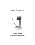
1
å
Demonstration Network
Car Audio
System Installation Manual
2048 Mercer Road, Lexington, Kentucky 40511-1071
Phone: 859-233-4599 • Fax: 859-233-4510
Customer Toll-Free USA & Canada: 800-322-8346
Website: http://www.audioauthority.com
The Access™ Demonstration Network is protected by U.S. Patent numbers 5,422,631 and 5,646,602 with
foreign patents pending.
Audio Authority, and the double-A symbol are registered trademarks of Audio Authority Corporation.
Access, AccessEZ, AccessPC, SilenTouch, AutoDamping, AutoLimiting, AutoCal, and TheftAlert are
trademarks of Audio Authority Corporation. The software imbedded within the Access™ System is not sold,
but rather licensed for this product specific use. The original purchaser is licensed to use this software in this
product and this application only. Under this license, the software may not be reproduced, copied,
disassembled, distributed by any means, licensed, rented, sold, or in any way revealed to or used by a third
party.
752-267
9/00
2
Contents
Orientation
INTRODUCTION .................................................................................. 4
DEFINITION OF TERMS ...................................................................... 5
HOW THE ACCESS™ SYSTEM WORKS ............................................. 7
ACCESS SYSTEM COMPONENTS .................................................... 8
Planning
CHOOSING THE CORRECT SWITCHING MODULES ..................... 12
HEAD UNITS ...................................................................................... 12
PROCESSORS, EQUALIZERS AND BYPASS .................................. 12
AMPLIFIERS AND AMP SHARING .................................................... 13
AMPLIFIER BYPASS .......................................................................... 14
SPEAKERS ........................................................................................ 14
Installation
PREPARATION ................................................................................... 15
ADDRESSING .................................................................................... 15
INSTALL THE SYSTEM HARDWARE ................................................ 19
INSTALL THE BUS CABLES .............................................................. 20
CHECK YOUR WORK TO THIS POINT .............................................. 26
INSTALLING A CONTROL PANEL .................................................... 28
CONNECT ACCESSORIES TO THE 980 SYSTEM MODULE .......... 31
TESTING NETWORK FUNCTION ..................................................... 32
COMPONENT HOOKUP .................................................................... 34
DEMONSTRATION FEATURES ......................................................... 38
Reference
APPENDIX A: SAMPLE SYSTEMS................................................... 40
APPENDIX B: PRODUCT CONNECTION DIAGRAMS ..................... 45
ACCESS WARRANTY........................................................................ 52
INDEX ................................................................................................. 53
3
Orientation
INTRODUCTION
The AccessEZ™ series of demonstration system modules provides a plug-in solution for car audio, hi-fi, and
video switching systems in retail display environments. This second generation of the highly capable, industry-acclaimed Access™ System modules offers many new features and benefits:
• AccessEZ offers a compact module to fit each kind of product, compared with a patchwork of printed
circuit boards.
• Modules are protected by attractive and rugged steel covers.
• Gold jacks and terminals are clearly and specifically labeled.
• Expansion, when needed, is done by directly “docking” modules.
• Simplified module addressing.
• New audio switching capabilities include Digital (coax) connections and Optical adapters for Toslink®
inputs and outputs.
• Master volume controls offer level presets.
• Touchscreen and Graphical control panels invite user interaction.
• Single product group control panel for sub rooms, speaker displays, or any product category.
All these new AccessEZ features are added to the existing capabilities of the Access System which include:
• Your choice of button-per-product, central control panel/computer touchscreen, IR remote, or any combination of user interface.
• Sophisticated SilenTouch™ interval muting for quiet switching.
• Capacity for hundreds of products.
• Comprehensive control panels with automated demonstration features.
• Single button recall of up to 99 stored system configurations.
All of these features make it EZ to design the demonstration system that fits your specific merchandising
needs. Your Account Manager and our Application Engineering staff can assist you in selecting and configuring the appropriate AccessEZ modules to build the ideal system for you.
This manual is provided as a framework to help you successfully install your Access System, test its operation,
and then use the system to demonstrate and sell your merchandise. This manual covers the proper installation of the switching system hardware only (if your system includes a 902, 903, or 906 Control Panel, or
AccessPC touchscreen interface, please refer to the separate User Guide provided with your control panel for
operation instructions).
Please read and follow these instructions carefully. If you have any difficulties during the installation, don’t
hesitate to call us for assistance! We are always pleased to receive customer calls. We’re open Monday
through Friday from 8:30 AM until 5:00 PM, Eastern Time. Also check our website for diagrams and tips:
http://www.audioauthority.com.
4
What is the Access™ System?
The Access™ System consists of a variety of intelligent switching modules. These modules communicate with
each other via the “system bus,” allowing you to construct the exact demonstration system configuration you
desire from the sources, processors/equalizers, amplifiers, speakers, and subwoofers in your display. The
switching modules are located near the actual products on display creating a “distributed switching network.” The products are connected to the modules rather than being wired to one central point. Selected
product signals are then sent across the network through “buses” that interconnect the modules. A simplified
view is shown below.
Figure 1.
CONTROL PANEL CABLE
SYSTEM BUS
Control
Panel
Source
Switching
Module
System
Module
Amplifier
Switching
Module
Left
Speaker
Switching
Module
Right
Speaker
Switching
Module
Remote
Control
Product
Select
Button
LOW LEVEL BUS
SPEAKER BUS
DEFINITION OF TERMS
To successfully install your new Access Demonstration Network, you should
familiarize yourself with the following terms:
Address
A number that pinpoints the identity and location of a
switch module within a system. The installer sets numeric
switches like the ones in Figure 2 for each module which
provides a unique address in the proper sequence for each
component connected to the system.
Figure 2. This example shows an
address setting of 0/00. Typically
this would represent the first
module (components 1 through 4)
in the Source Product Group.
AutoDamping™
When merchandising many pairs of different speakers in a
showroom, the drivers of the unselected speaker pairs
become passive radiators when the currently active
speaker pair is playing, absorbing much of the sound
coming from the speakers being played. AutoDamping™ is a circuit in the Model 932 that
electrically disconnects (shorts) speakers not being played, thereby automatically damping
them as passive radiators and improving sound quality in the showroom.
Bus
A Bus is a pathway for signals to travel from module to module; a cable connecting
modules. There are three types of buses found in most AccessEZ Systems:
• System Bus A four wire harness (red, black, yellow, blue) connected to every
AccessEZ module. The System Bus carries the signals that control the selection of
the components and perform various housekeeping functions among the modules
in the system.
• Speaker Bus (or High Level Bus) A four wire harness (green, white, brown, gray)
that carries speaker-level signals from source and/or amplifier modules to
speaker modules.
• Low-level Bus A signal bus using RCA patch cables to carry low-level audio
signals between source modules and equalizer or amplifier modules.
5
Bypass
A way to hear a system without a particular in-line component (EQ, Crossover, Amplifier,
etc.). For example, when you wish to hear a system without the processor, the system can
route the signal past the processor group and directly to the amplifiers. In this expample,
Position #4 on the last module in the Processor Product Group is used as the bypass
location. When this position is selected, or the Product Group is deselected, the audio
signal continues through the bypassed group to the next Product Group. To activate
bypass, turn ON the Bypass switch only on the last module in the group.
Control Panel
Control Panels, like the 902, 903, 906 or AccessPC Touchscreen, add central control and
display capabilities to a system. Any control panel can operate hand-in-hand with product select buttons.
Module
A basic component of the AccessEZ™ System. There are five types of modules normally
found in car audio applications:
• Switching Modules select and connect products for demonstration and communicate with other system components through the System Bus. Examples are
Models 910D, 922, 932, 942 and 958.
• Expander Modules add channel capacity to switching modules. Examples are
Models 920X and 940X.
• System Modules perform basic control, interface and housekeeping functions
within the system. Examples include Models 980 and 988.
• DC Power Modules distribute DC power to sources, EQs, and amps. Examples
include Models 915X and 916X.
• Signal Distribution Modules, such as the 985EZ and 975, distribute audio and/or
video signals to output devices such as Video monitors.
6
Position
The numbered point of connection (1-4 for electronics, or 1-8 for speakers) of a product to
a switching or expander module. The product select button (PSB) must be connected to
the corresponding position on the module. For example, if a component is connected to
position 3, its product select button must be connected to PSB position 3. When a “bypass”
is required, always use the fourth position (see “bypass”). Control Panels select positions
through the System Bus, and are not connected to individual positions.
Product Group
A group of functionally similar products, such as sources, amplifiers, subwoofers, etc.
product group also refers to the windows to the right on 902/903 control panels.
Product Select
Button (PSB)
A push-button mounted at, or near the product location. Pushing this button selects the
product for demonstration and lights an LED to confirm the selection.
System
1. A network of switching modules interconnected by buses where a control panel and/or
PSBs are employed to select and thereby interconnect specific components for demonstration. 2. A configuration of audio products or components playing together which can be
stored in control panel memory and A/B compared with other “systems.”
SilenTouch™
SilenTouch mutes the sound for a brief period during the switching process to eliminate
transient noises while changing from one product to the next.
TheftAlert™
A special circuit that senses ground continuity of the products connected to the switching
modules. If an alarm device is connected to the system, it will sound if a product is
disconnected from the system without authorization. TheftAlert is an optional feature
available through your Audio Authority® Account Manager. TheftAlert may also be added
after your initial purchase. A special transformer is required for the feature to work and is
provided per your request. You then will need to install it in the proper position on the
switch modules.
HOW THE ACCESS™ SYSTEM WORKS
When a product is selected for demonstration, signals are sent through a network of buses between switching
modules to activate that particular product position.
Selecting Products in the Access System
Products can be selected in a system in different ways that can all be combined into a single system, if desired.
You may select products in the following ways:
• By pressing a Product Select Button (PSB) connected to a switching module. This allows the user to build
different systems of product configurations manually.
• By using a control panel, if the system is so equipped. Control panel use is covered in detail in a separate
manual that accompanies each control panel.
• By issuing commands with the Model 905 IR Remote Control, which is included with the 902 Control
Panel and available with the 903. One 905 remote is recommended per salesperson.
• By using a computer touchscreen with AccessPC or custom software configured to enable product selections and other control functions.
• A combination of these methods.
Buses
Signals are passed between modules by “buses,” which are nothing more than cables that go from module to
module to module, connecting them into functional groups within the system’s architecture.
The System Bus connects all switching and system modules, allowing them to send messages to each other,
controlled by the addresses that are set by the installer. These signals instruct the modules to select the
inputs/outputs of a particular unit, such as a head unit or amplifier. Expander modules are not connected
directly to the System Bus. Each expander receives its instruction from the main switch module to which it is
attached.
Signal Buses carry audio signals, either low-level (source low-level output, for example) or high-level signals
(amplifier output).
System Bus
922
980
942
932
Left
Low Level Bus (Source Bus/Amp In Bus)
932
Right
Speaker Bus
Figure 3. Basic bus examples in a simple demonstration system.
7
ACCESS SYSTEM COMPONENTS
If you have already planned your system with the assistance of your account manager, you may wish to skip
directly to the Installation section. If you do not have a complete plan for your system, get help from your
Audio Authority® Account Manager by calling 800-322-8346.
Access™ User Interfaces
Control Panels
902 Full-Featured Control Panel
Includes one 987 Equal Volume Comparison (EVC) module, one microphone with 25’ cord, and one
905 IR Remote Control. Because the remote control serves such an essential function in a demonstration, one remote control is recommended for each sales person.
MODEL 902 FRONT PANEL
ASD
å Demonstration Network
MODEL 903 FRONT PANEL
HEAD UNITS
ASD
å Demonstration Network
Patents Pending
1
2
3
A
4
5
6
B
7
8
9
C
EQ/PROCESSORS
FRONT AMP
1
2
3
A
4
5
6
B
7
8
9
C
EQ/PROCESSORS
FRONT AMP
FRONT SPEAKERS
0
FRONT SPEAKERS
0
SECURE
SECURE
REAR AMP
SilenTouch ™
HEAD UNITS
Patents Pending
EQUAL VOLUME COMPARISON
REAR AMP
SilenTouch ™
Theft Alert
Theft Alert
REAR SPEAKERS
REAR SPEAKERS
SUB AMP
SUB AMP
SUB SPEAKERS
SUB SPEAKERS
ATTENUATION / SPL
ON / SPL
(STORE)
MUTE
(ADJUST)
DECIBELS
ATTEN.
LEVEL
P-NOISE AUTO-CAL
Model 902 Control Panel
Model 903 Control Panel
Figure 4. The 903 performs all the functions of the 902 except EVC and SPL AutoLimiting™, and the IR remote is optional.
902 Features include:
• Displays selected products, even when they are selected using Product Select Buttons or by remote
control. Displays diagnostic information for troubleshooting the system.
• Removable Product Group insert labels can be changed to indicate the functions of the LED
displays. An extensive set of labels is included with the control panel.
• Amplifiers can be connected to more than one Product Group allowing one amplifier to be demonstrated independently as a front, rear, or sub amp (amp sharing).
• If not assigned as an active Product Group, the control panel’s last Product Group can store up to
99 pre-configured systems for immediate recall.
• Speakers with varying input sensitivities can be equalized to play at matched volumes by attenuating the output level of the source. AutoCal™ program can run automatically or calibration
values can be directly written into the system’s memory.
• Optional TheftAlert™ circuit can be armed to sound an alarm should products on display be
disconnected without authorization.
8
• The control panel or any specific Product Group can be “locked out” from unauthorized user
input.
• Auto SPL controls the maximum volume level of the currently selected system. The maximum is
120 dB.
903 Control Panel
Similar to the 902 Control Panel, but does not include the 987 EVC module, so Equal Volume Comparison and Auto SPL are not available. The 905 IR Remote will operate the 903 Control Panel but is
not included, and must be purchased separately. All other functions of the 902 are inherent with the
903.
904 Product Group Expander for Control Panel
Adds eight additional Product Groups to your control panel. Up to 32 unique Product Groups can
exist in an Access™ System.
904V Product Group Expander and Volume Control
Adds four additional product groups to your control panel and provides a master volume control.
905 IR Remote
Full function Infrared Remote Control for 902 and 903 Control Panels.
906 Control Panel
Perfect for single product group displays such as subwoofer rooms or speaker walls, the 906 Control
Panel selects products using a rotary encoder knob, and displays the selected product number in the
LCD window. Use the Select Previous button to make instantaneous comparisons between products.
988CP0 Volume Control Panel
Provides master volume for Access demonstration systems.
Product Select Buttons and Indicators
Various button styles, sizes and colors are available. All have integrated LEDs to indicate when the
product is selected. Product indicators are simply LEDs mounted by each product showing which
products are playing.
Switching Modules
910D Head Unit Selector
Controls outputs from 4 source units for 4-channel high-level, 2-channel low-level operation. Provides DC power connection for each source. Module can be split in two for greater placement
flexibility using a Model 998 Extension Cable. Also features an expander port for adding additional
channels.
922 Low-Level Selector
Controls a pair of 2-channel low-level signals routed to or from 4 low-level products such as low-level
sources.
932 Speaker Selector
Accommodates 8 left OR 8 right speakers. Two 932s are required for 8 stereo pairs. Non-selected
speakers are shorted to ground to reduce the sound absorption of unselected speakers in the display.
9
940EZ High-Level Selector
Controls two channel high-level signals routed to or from four high-level products. Controls two
channels of four products (e.g., high-level sources). Use Model 932 for applications where AutoDamping™ is desired.
942 2-Channel Amplifier Selector
Switches the low-level inputs and high-level outputs of four 2-channel amplifiers.
958 EQ or Crossover Selector
Controls low-level inputs and six channels of low-level outputs from four crossovers or equalizers.
System Module
980EZ
Provides the central point of control for DC power, SilenTouch™, 902/903 Control Panel,
TheftAlert™ output, and so forth. The 980 is essential for any Access™ System and is typically
installed in the low-level signal path just prior to any amplifier inputs.
Expander Modules
920X and Low-Level Expansion Module
The 920X adds a pair of low-level channels to any switching module.
940X High-Level Expander Module
Adds a pair of high-level channels to any switching module.
System Specific Components
970 RS232 Serial Interface/PC Interface
Connects the Access system to a PC for computer control (Touchscreen, etc.).
971 Infrared Control Module
Customized to send IR commands to infrared audio and video components.
977 Digital Audio Adapters
977R converts optical digital audio signals to coax, and 977T converts coax digital audio signals to
optical.
975 FM Distribution Amplifier
12-volt powered FM antenna booster drives all the radio antenna inputs and has direct input for one
or more RF output CD changers. Use with distribution components in Kit 16 or Kit 17. Kit 16 provides 4-way taps and cables for FM distribution to sixteen head units. Kit 17 contains one 4-way tap
and cables for four head units.
9A80 Crossover
A simple crossover which can be hidden inside the fixture, allowing two-channel low-level signal
from the headunit to be split for the demonstration of front speakers, rear speakers, and subwoofers.
981 DC Eliminator
Small, in-line, low-level device that eliminates DC that can be present in the low-level outputs of
some head units and crossovers found on the market. One required per offending product.
10
982A Low-Level Isolator
Small in-line, low-level device that eliminates ground loops inherent in car audio displays. One
required per amplifier group (982A is not recommended with subwoofer groups).
983 Four-Channel AutoMatch Module
Device used to protect high-level in/out products on display that have different ground schemes.
Device will protect products from harm when a floating ground source is selected to play with an
amplifier. If needed, only one unit is required per display when demonstrating high-level head units
in combination with power amps.
985EZ A/V Distribution Amplifier
Distributes component video signal to up to 8 video monitors.
987 EVC Audio Level Module
Adds 4 channels of Equal Volume Comparison and SPL AutoLimiting to the 902 Control Panel (one
987 is shipped with each 902).
990 External Infrared Receiver
Ceiling mount, omnidirectional IR Receiver used to extend the 905 Remote Transmitter’s range for
greater line-of-sight distances with the 902 or 903.
993 Amp Sharing Adapter
Allows easy hookup for one amplifier to be selected for any of three positions (e.g., Front, Rear or
Sub).
DC Distribution Modules
915X DC Power Adapter
DC expander Module that provides connections to DC power source for 4 Equalizers, Crossovers, or
CD Changers. Includes resettable 10 amp circuit breaker. Use with Model 922 or Model 958.
916X DC Power Adapter
DC expander Module that provides connections to DC power source for 4 car audio amplifiers. Uses
resettable 10 amp circuit breaker for ignition circuit and 40 amp resettable circuit breaker for circuit
from battery terminals. Use with Model 942. The 916X also provides the DC connection points for
980EZ, 910D and 915X modules.
11
CHOOSING THE CORRECT SWITCHING MODULES
The Access™ System is very
versatile and can be installed and
wired in many different ways,
including the wrong way. Your
Account Manager can help you
choose the modules that will best
suit your needs. If at any time
you wish to change your merchandising approach, Access can
be rewired and additional
modules can be installed to
accommodate a different configuration.
Product Groups
Front Speakers
Source Units
Front Amps
Processor/EQs
Rear Speakers
Rear Amps
Figure 5. Basic car audio
signal flow for a system
including Front, Rear and Sub
amplifier and speaker Product
Groups.
When planning the installation,
Sub Amps
try to think of the components
you wish to display as belonging
to a particular family or GROUP, and where those components might
reside in the signal path, for a typical vehicle installation.
Subwoofers
Head Units
The Model 910 is a good choice for almost every type of head unit, from
simple 2-channel powered tape/tuner units with only high-level
outputs, to CD/tuner units that have low-level outputs (preamp) for
rear channels and high-level outputs (speaker-level) for front channels.
Both of these varieties belong to the same source family or Product
Group and may be switched with the Model 910D (see Figure 6).
Processors and Equalizers
Figure 6. Basic Head
Unit hookup with high
and low-level plus DC
power.
910
The next logical Product Group in the signal path may be Processor/
EQs/Crossovers. Generally, these devices have 2-channel (stereo) lowlevel inputs that are processed through a dividing network to derive multiple output channels
(e.g. 2 in x 6 out; see Figure 7). Products in this group are usually wired in the signal path just
prior to the amplifier(s) input. Most of these processors have a wide range of adjustable
controls that, when over-adjusted, can interject noise (distortion, hum, etc.) into the system.
Check the gain setting controls, crossover frequency, and other control settings on your
products often. Powered Equalizers would not be included in this Product Group. For the
bypass option, remember to leave the fourth position open on the last 958 module in the
Processor/EQ Product Group. That position is reserved for the bypass connection, so no
processor or EQ can be connected (see pp. 6, 40).
DC Power
915X
Source In
958
Front Out
Rear Out
Sub Out
Figure 7. Basic Processor/EQ
hookup for low-level inputs and
outputs with DC power.
12
You may not wish to buy the extra switching modules to create a
separate Product Group for Processor/EQs, especially if you only carry one or
two models of crossovers or passive EQs. However, if you want more than one
amp to play at any given time, there should be at least one device (a crossover
or processor) in the signal path that can accept a 2-channel low-level input from
a source, and deliver front, rear and sub low-level outputs to amplifiers. Many
retailers use a single dedicated crossover, buried inside the display, to derive
multiple output signals for multiple amp inputs. This may be the simplest
solution for your display (see Figure 8). Our Model 9A80 Crossover was
designed just for this purpose. Call your Audio Authority Account Manager for
details (800/322-8346).
Head Unit Low-Level Bus
Dedicated EQ
980
Low-Level
Buses
916X
942
Amplifier Product Groups
The low-level outputs of products in the Processor/EQ/Crossover group are
connected to the next logical component in the signal path, the Amplifier
Product Group. Generally, amplifiers come in two different varieties; those
that have low-level and high-level inputs and those that only have high-level
inputs, normally called “boosters.” These two types of amps require different
switching modules and belong in different Product Groups. If there are no
booster-amps in your display, then you probably want to divide the amplifiers you wish to display into Front-channel amps, Rear-channel amps, and
Subwoofer amps (see example in Figure 8).
Many of today’s amps have multiple inputs and outputs such as 4-channel
amplifiers with Front Left/Right-INs/OUTs and Rear Left/Right-INs/OUTs.
There are 6-channel amplifiers, most with their own internal crossovers, and
amplifiers that can be specially configured, depending on how you hook them
up (e.g. Front L/R Stereo IN/OUT, Rear bridged in mono for Subs).
Front
Amps
916X
942
When planning for demonstrating these
multichannel amps, you will need to
support each L/R input to the amp, and
each L/R output from the amp.
Front
942
Rear
Amps
916X
942
Sub
Amps
Figure 8. Dedicated EQ and Front/
Rear/Sub Amp Groups.
Sub
916X
916X
PSBs
Front/Sub
942
So, a 4-channel amp could be used as
shown in Figure 9. The Front L/R Input
Input
signal would come from the Processor/EQ
Product Group to the Front amplifier
Product Group’s Model 942 Amplifier
Selector through the Front Low-Level Bus.
The amplifier in position #1 receives the
front input L/R signal through the 942 Amp
Module and sends its front output L/R
Output
signal back through the 942 in the Front
Figure 9. 4-channel amplifier switching
Amp Product Group. The Sub input signal
(Front/Rear or Front/Sub).
in this example passes through position #1
on the 942 Amp Selector for the Sub Amp
Product Group. The High-Level Bus
then passes the signals on to the Front
916X
and Sub speaker groups.
Amp Sharing
It is sometimes desirable to have 2channel or 4-channel amplifiers
available to play in more than one
Product Group. For example, you may wish to show the same
amplifier driving a Front, Rear, or Sub speaker group. This method of
demonstration lowers your display inventory investment and conserves space.
942
942
942
Front
Rear
Sub
The Access™ System allows the user to share an amp in different Product
Groups. To achieve “Amp Sharing”, one must use a Model 942 for each
Product Group that the shared amp will appear in. Also, the amp must
receive an input signal from the processor’s output for each source or source
unit group (see Figure 10). There are several ways to set up amp sharing
systems, so call Audio Authority at 800-322-8346 with questions.
993
Model 993
Amp Sharing
Adapter
Shared
Amplifier
Figure 10. One shared amp may be
selected for front rear or sub positions
(see Appx. B p. 48).
13
Ampifier Bypass
The source signal is supplied when no products in an amp group are selected. For the bypass option, remember to leave the fourth position open on the last 942 module in each Amp Product Group. That position is
reserved for the bypass connection, so no amp can be connected there (see pp. 6, 40).
There are many other hookup and demonstration possibilities for amplifiers, many of which are shown in this
manual. Please call us at 800-322-8346 if you have questions about the type of switching modules you need,
or with any other questions.
Speakers
The final component(s) in the signal path are the speakers.
Each speaker Product Group is powered by the selected
amplifier in its corresponding group. So, front type
speakers are powered by front amps, rear type speakers by
rear amps, etc. The Access System’s architecture was
designed for a maximum of 16 unique speaker groups,
with a capacity within each group for 99 pairs of speakers.
Possible Speaker/Amplifier Product Groups
Front Speakers
Rear Speakers
Subwoofers
Tweeters
Mid Range Speakers
Subwoofers
Figure 11. Some suggestions for group arrangements.
Sixteen unique speaker groups are possible.
Speakers use the special 932 switching module. Each 932 switches eight speakers in one channel (8 left or 8
right speakers) so two Model 932s are required for each eight pairs of speakers. The 932’s AutoDamping™
circuit shorts unselected speakers to ground so that they do not resonate sympathetically with the selected
speaker pair.
In very small systems, it could be more cost effective to use the Model 940EZ high-level switching module for
speakers. Each 940EZ module handles 4 pairs of speakers. Unselected speakers are NOT shorted to ground
(AutoDamping) when the 940EZ is used, but that usually isn’t an issue when there are only a few speaker pairs
in the system.
Figure 11. Model 932
Speaker Selectors. This
configuration could switch
eight speaker pairs.
14
932
932
Figure 12. Model 940EZ.
This module could switch
four speaker pairs, but does
not have the AutoDamping
Circuit.
940
BEGIN INSTALLATION
1. Preparation
Follow these steps carefully:
A. Review the design of the demonstration area.
• Make sure the display fixture is correct for your installation.
• Look at the supplied system wiring diagram, or choose one from this manual to serve as an
example. Examples are in Appendix A: Sample Systems.
• Gather the owner’s manuals of other products that are part of your system for reference during
the installation.
B. Gather the tools and materials you will need.
You will need at least the following:
• #1 and #2 Phillips screwdriver bits
• #1 small slotted screwdriver
• Power screwdriver (especially one with a torque clutch)
• Wire cutter/stripper
• Cable ties (4” is good)
• 7/64” and 3/4” drill bits
• 7/16” nut driver or open-end wrench
• flashlight
• 14 - 18 gauge speaker wire
• high quality RCA patch cords
C. Check the contents of the shipping cartons. If your system is not pre-installed, use the packing list and
your wiring diagram to identify the system components and determine how each component fits into your
wiring plan. Refer to the list of Access™ System Components on page 8 to help identify the various items.
2. Address and Other Settings
The Access System is made up of smart modules, able to communicate with each other and a control panel
when appropriate. Each “main switching module” (see Figure 14) has a set of rotary switches for assigning
its unique ID or “address.” There are two parts to the address: the “group” number and the “module ID”
number. The group number is the general place a module resides in the system, like a street in a city. The
module ID is the unique number assigned to each module like individual house addresses on one street.
Therefore, each module ID must be unique within the same product group.
958
922
932
A. Number the Product Groups.
First, determine the portion of the address called the group number. A basic
group address example is shown below. The column to the right shows the
order in which groups appear on the 902 Control Panel. Refer to your
system plan to make a chart like the one below. Number each Product
Group starting with Head Units (always Group 0).
942
940
Figure 14. Main Switching Modules
and location of Group switch. (Model
910D is always Group 0.)
Electronics
Product Group
Head Units
Processor/EQs
Front Amplifiers
Rear Amplifiers
Sub Amplifiers
Speaker
Product Group
Group
Number
902/903 Control
Panel Display
Front Speakers
Rear Speakers
Subwoofers
0
2
4
5
6
1
2
3,4
5,6
7,8
15
Note that the front amps and speakers
have matching group numbers as do
the rear amps and speakers. As a rule,
related amps and speakers have matching group numbers; this determines
how the 902 Control Panel, if used,
handles Volume Compensation of the
products in these Groups. Figure 15
shows how the 902/903 Control Panel
would arrange these product groups on
its Product Group display windows.
ASD
SOURCES
å Demonstration Network
Patents Pending
1
2
3
A
4
5
6
B
7
8
9
C
PROCESSOR/EQ
FRONT AMP
FRONT SPEAKERS
0
SECURE
REAR AMP
SilenTouch ™
Theft Alert
REAR SPEAKERS
EQUAL VOLUME COMPARISON
B. Determine the Module ID settings.
ATTENUATION / SPL
ON / SPL
Number the modules in each group to
put the products in the desired order in
the group. Use the following table for
the appropriate module ID setting for
each module.
SUB AMP
(STORE)
MUTE
ATTEN.
LEVEL
DECIBELS
SUBWOOFERS
(ADJUST)
P-NOISE AUTO-CAL
Model 902 Control Panel
Figure 15. This is how product groups appear on the 902 Control Panel.
The display shows which product in each group is selected.
Speakers
Sources, EQs and Amplifiers
Switching
Modules
910, 922,
958, 942
Addressing
Sequence for
Product
Positions
1st module:
2nd module :
etc...
1-4
5-8
9 - 12
13 - 16
17 - 20
21 - 24
25 - 28
29 - 32
33 - 36
37 - 40
41 - 44
45 - 48
49 - 52
53 - 56
57 - 60
61 - 64
65 - 68
69 - 72
73 - 76
77 - 80
81 - 84
85 - 88
89 - 92
93 - 96
97 - 99
Set the MODULE ID to:
slide
switch
0-9
0-9
0-9
0-9
0-9
0-9
0-9
0-9
0-9
0-9
10 - 19
10 - 19
10 - 19
10 - 19
10 - 19
10 - 19
10 - 19
10 - 19
10 - 19
10 - 19
20 - 29*
20 - 29*
20 - 29*
20 - 29*
20 - 29*
rotary
switch
0
1
2
3
4
5
6
7
8
9
0
1
2
3
4
5
6
7
8
9
0
1
2
3
4
Addressing
Sequence for
932
Product Grps
Set the MODULE ID to:
slide
switch
rotary
switch
1-8
9 - 16
17 - 24
25 - 32
33 - 40
41 - 48
49 - 56
57 - 64
65 - 72
73 - 80
81 - 88
89 - 96
97 -99
0-9
0-9
0-9
0-9
0-9
0-9
0-9
0-9
0-9
0-9
10 - 19
10 - 19
10 - 19
0
1
2
3
4
5
6
7
8
9
0
1
2
How to Use These Tables
Read accross from left to right. For the 1st
module’s addressing sequence (products
one through four) set the MODULE ID to
“0 - 9” on the slide switch, and “0” on the
rotary switch.
* Contact the factory if this address is needed.
16
C. Set the Address Switches.
Some Group settings are made at the factory, and cannot
be changed later. Figure 16 shows the first switch module
(Model 910D) in the first Product Group (head units). It
has a default address of Group #0 (set at the factory) and
the Module ID is set to #00 (this lets the system know this
module is connected to the first four products in this
product group). The second 910 would be addressed 01,
and the third module, 02, etc. Always start with zero, not
one, for the first module in any group.
Figure 16. First head unit Module with the
address 0/00 (Group/Module ID).
Figure 17 shows the address settings for the fourth module in the
Processor/EQ Product Group. The group default is #2 and the
address is set to #03.
D. Set the Programming Switches.
Figure 17. This Model 958 would be the
fourth and last module in group 2
(Processor/EQs), because bypass is ON.
Programming Switch Settings “S M B T D.”
Models 910, 940EZ and 942 have a DIP switch array with small
rocker switches labeled S M B T D (Model 910 has T and D only).
The slide switches are set to “Off” at the factory. The switches are
defined as:
S
M
B
T
D
Single Multi- Bypass Time
Delay
Stereo Channel
“D” turns on the DC Power Delay feature and works with the
Power Mode switch setting on the 980 module. Use the following
chart to determine switch settings. Set the 980’s “Power Mode”
switch and each main module’s “D” and “T” switch using the chart
below.
Figure 18. The thirteenth (and last)
module in Group 4 (Front Amps).
Bypass is ON (“B” in programming
switch array SMBTD).
Mode
Effect on
Product Groups
Power Mode
Switch on 980
Delay or “D” Switch
on Main Modules
Power Conserve
1 unit ON;
delayed turn-on
ON
ON
Smart Power
Up to 3 units ON;
delayed turn-on
OFF
ON
Continuous Power
All units ON;
no turn-on delay
OFF
OFF
“T” sets the amount of time delay to allow for product turn-on, if “D” is ON.
“T” - OFF = 3/4 second delay for head units and low power amps.
“T” - ON = 3 second delay for high power amps using switching power supplies.
The “T” switch should be OFF (3/4 second delay) for 910 modules, and ON for 942 modules (3 second turnon delay for large power amps).
Also, see “Choosing the Power Mode for Your System” on page 24 for more detailed information on the three
different Power Mode settings available for your Access™ System.
17
“B” should be set to “OFF” unless you wish to BYPASS the product group associated with the
module. The bypass module is always the last module in the product group to be bypassed (only the
bypass module should have the “B” switch turned ON). A product group will be bypassed when all
products in that group are unselected. Bypass is commonly used in systems where there are both
low-level and high-level output signals from head units (see Appx A, page 40 for a hookup diagram).
“M” has special functions for multi-channel amps and should be set to OFF. Call the factory for
details.
“S” is related to “M” and should remain OFF in most
cases.
Set the Left-Right Switch.
Set the 932 Left-Right switch to indicate its position on the
right or left side of the speaker portion of your display.
932s are the only modules addressed identically, but the
Left-Right switch lets the control panel tell them apart. Set
the switch to RIGHT if only one channel (a single 932) is
used, as in the case of mono subwoofers.
Set the Address Switches.
Set and recheck all the address switch settings. Setting the
address switches is very important. All functions of the
Access™ System depend on correct addressing of the
switch modules. Please take the time to double check the
labels and subsequent module addresses that you may
have set.
Timeout Minutes and Model 988.
Figure 19. The 932 module serving the left channel of
speakers 9-16 (note the filled-in identification boxes).
Model 988 (if included in your system) can monitor system
activity and restore system volume to a standby level
during idle periods. This time period is called “Timeout” and is counted from the last Master Volume
control change or Access™ System command such as product selection. Set the 988 “Timeout” DIP
switches to total the desired timeout period. For example, if you turn on switches 1 and 2, your
system will timeout after 3 minutes. If you do not wish to use the Timeout feature, leave the three
Timeout switches turned OFF.
SilenTouch™ and Model 988.
The Model 988 can administer SilenTouch™ in systems with no 980 module. If both modules are
present in a system, turn the 988’s SilenTouch switch OFF (the bottom switch on the 4-switch array).
Speaker Limit.
The Access System is designed to allow multi-channel amps to play a set of car speakers by separating
them into product groups. One amplifier plays two Fronts, two Rears, and two Subwoofers. Additionally, Access allows a default of two speaker pairs to play at once in the same Product Group (e.g.
two pairs in the Front Speaker Product Group). Some stereo amp manufacturers do not recommend
playing more than one pair of speakers at a time. If customers will have access to your display,
consider using the lowest Speaker Limit recommended for any amplifiers you are demonstrating.
You may set the Speaker Limit to 1, 3 or 4 pairs with the switch array labeled SPEAKER LIMIT on the
Model 980 (default is 2 pair). If your system has a Model 988 instead of a Model 980, the speaker
limit is set at two.
E. Fill out the identification boxes.
Fill out the identification boxes printed on the case of main modules to reflect the address and other settings
on each module (see Figure 19). This will help with installation and troubleshooting later.
18
3. Installing the System Hardware
A. Designate the Switching Module Locations.
Each switching module controls either 4 or 8 components. Follow your system plan drawing to determine
the location of the switching modules in the display fixture. If you are using factory provided bus cables, you
may wish to connect all the modules that share the system bus with system bus cable, power up the system
on a bench or table, and check the switching modules and control panel logic before actually installing the
modules in your fixture.
1. Mark the location of the switching modules and any related expander modules near the center of
the products they will serve. Some modules will serve 4 products, others will serve 8 products.
2. Be sure to consider the 2 foot plug spacing if you are using factory pre-made bus cables.
B. Determine Other Module Locations.
In the following installation steps, ignore any references to modules that are not part of your system.
1. Position the 980 System Module in the signal path immediately prior to the first module(s) in your
Amplifier Product Group(s). This position will allow you to pass signals from the output of your
Head Unit or Processor/EQ Product Group to the 980 Module which will then pass the low-level
input signals to your Amplifier Product Group(s).
2. If you have “Booster Amps” with high-level inputs in your system, you must use a Model 983
AutoMatch™ Module to protect the components in your display from damage. The 983 is required
to “match” floating ground output source units with common ground input amplifier units. The
983 should be located near the 940EZ and 940X switching and expander modules that send and
receive signals to and from the booster amps in your display.
3. If your system has a Model 902 Control Panel, you also received a Model 987 EVC Control Module. The 987 Module should be positioned just after the 980 System Module in the Low-Level Bus.
When connected, the 980 will receive signals from the 987 Module and send low-level input
signals to your Amplifier Product Group(s). There is a hook up diagram
on Page 4 of the User’s Guide for the 902 Control Panel.
C. Mount the Modules.
942
920X
WRONG
DC Port
1. Mount the main modules first, then plug in and mount signal and
DC expander modules in the system. Use the screws provided.
2. Connect an audio signal expander (if any) such as 920X or 940X to
its respective main switching module as shown in Figure 20. It is
critical that the signal expanders be connected to the header port on
the main module labeled “Expansion.” DO NOT plug an audio
signal expander module to the header port labeled
“DC Expansion.”
916X
RIGHT
942
DC Port
Signal
Expander Port
RIGHT
Signal
Expander Port
920X
Figure 20. Audio signal
expander connection
3. Connect each 915X and 916X DC Expander Module to its respective main
switching module and attach with screws provided. Be certain to connect DC
expander modules to the header port on the main module labeled “DC EXPANSION.” DO NOT plug a DC expander module to the header port labeled
simply “EXPANSION.”
WRONG
916X
Figure 21. DC Expander connection
19
4. Installing the Bus Cables
Pre-assembled bus cables or the raw materials to make the necessary bus cables on the job site were included
with your system purchase. Pre-assembled bus cables have connectors every two feet (RCA patch cords are
available in lengths from three to twenty feet). If you plan to make your bus cables on the job site, you’ll need
a special assembly tool available from the factory.
If you are making your own bus cables, be very careful to follow the assembly instructions, especially concerning wire to connector polarity. Incorrect bus fabrication can cause system failure and damage!
Several types of bus cables are available for specific purposes:
Cable Type
Color Code
Pre-assembled
Part Number
Cable for
Site Assembly
System Bus
Speaker Bus
Low-level
Bus
System extension*
Speaker extension*
yellow/red/blue/black
green/white/brown gray
RCA patch cords
yellow/red/blue/black
green/white/brown/gray
802-307
871-055
802-186
871-045
801-018 to 801-023 EX2, EX1
802-323
871-055
802-309
871-045
Plug for
Assembly
Site Assembly T o o l
916-0470
904-172
SGRCA
916-0470
904-172
762-011
762-009
762-006
762-011
762-009
* The System and Speaker Bus extension cables allow you to join remote sections of the Access™ System with the main electronic component
section of your display, as in the case of rear speaker towers.
Any RCA patch cords are suitable for the low level bus or component connections; however, we highly
recommend that you use our special low-capacitance RCA patch cables for optimum system performance and
reliability.
A. Install the System Bus
The system bus connects only to main switching modules (910, 920, 958, 942, 932, 940), not expanders (920X,
940X, 915X, 916X).
940
910
Figure 22.
Connect System
Bus to every
Main Module.
4. Start at one end of your system and work toward the other end, connecting the system bus to every main module.
5. If you are using Pre-assembled buses, you may use a system bus extension cable for long distances between modules, or carefully splice 18
gauge cable where needed.
YELLOW WIRE
ALWAYS ON
THIS SIDE OF
PLUG
GROUP
3. Connect the system bus to all modules having headers marked SYSTEM
BUS. The connectors are polarized, so they will only connect in one
direction, but always make sure to prevent the possibility of plugging the
system bus to the header backwards (see Figure 23).
20
932
942
DULE ID
2. Mate one plug of the system bus cable with
either of the 4 pin headers marked with the
yellow/red/blue/black color code on each
switching module.
958
K
AC E
BL LU D
B
RE W
O
LL
YE
1. Use the pre-assembled system bus
cables supplied with your system or
922
install the 4 pin plugs onto the
system bus wire using the special
tool. If you are making your own
system bus, be sure to leave a small
amount of slack in the wire between the
modules and be very careful to observe correct
polarity.
SYSTEM
BUS
Figure 23. Observe correct System
Bus polarity. It is fine to leave one
header unused.
6. Dual header connections are provided on all modules so you can easily extend a bus cable that is too short,
or you can branch off the main run to a remote or side group of modules, if necessary.
Note: Since bus connectors can be both in and out, one header connection may be left open. The
remaining connector may be used to create a branch from the bus.
B. Install Speaker Bus.
The procedure for running the Speaker Bus is very similar to the installation of the System Bus. The speaker
bus will be used to send high-level signals from amp outputs to speaker modules in the system. (For very
small systems with no amps, the head unit group is connected directly to speaker
groups via speaker bus.)
SPEAKER
BUS
• Connect related modules with a continuous run of bus cable.
• Start from the module at one end of the group and work toward the
other end.
• Run separate buses for front, rear and sub (or tweeter, mid, and sub).
GREEN WIRE
ALWAYS ON
2. Using the same bus cable or branching off with a new section of bus cable, continue
connecting all 932 modules in the Front Speaker group to the Front Speaker Bus.
AY N
GR OW
BR HITE N
W REE
G
1. Using the a green/white/brown/gray bus cable assembly, plug a connector of
THIS SIDE OF
PLUG
the bus into a SPEAKER BUS header on each 942 module in the Front Amplifier group. The connectors are polarized, so they will only connect in one
direction, but always make sure to prevent the possibility of plugging the system bus to
the header backwards (see Figure 24).
Figure 24.
3. Connect all remaining Amplifier/Speaker Product Groups in the same way.
4. Extend system or speaker buses, if necessary, using the available extension cable assemblies.
C. Low-Level Buses.
The rules are similar to those for installation of the other signal buses:
• Connect modules within a group and to corresponding groups.
• Start from the module at one end of the product group and work toward the module at the other
end.
• Low-level cables are quite different from other bus cables. Use only high-quality shielded RCA
patch cords, preferably gold-plated, for low-level bus connections. Use Audio Authority®
Excellerator Cable and Solderless Gold RCA Connectors for made-to-measure cables of exact
length, especially for those runs over 6 feet.
Figure 25. Speaker Bus Example.
Left Front Speaker Group
932
932
Front Amplifier Group
942
942
Right Front Speaker Group
932
932
Front Speaker Bus
Left Rear Speaker Group
932
932
Rear Amplifier Group
942
942
Right Rear Speaker Group
932
932
Rear Speaker Bus
21
1. Using high-quality shielded RCA patch cords, connect the modules with low-level jacks (910, 922, 958, 980
and 942) along with any low-level expander modules (920X).
2. Connect all modules serving each pair of low-level channels in a given group, such as source outputs (910
or 922), front amp inputs or rear amp inputs (942).
3. Connect a module from each low-level group of modules to a module of the next low-level group in the
signal path. Here are two examples:
• Connect the source output bus to the processor bus input; if using a single dedicated processor to
derive additional amplifier product groups, connect the source output bus directly to the input of
the dedicated processor.
• Connect the processor output bus to the 980 System Module input bus; connect the 980’s output
bus to the amplifier bus input. The 980 has inputs and outputs to feed processor output signals to
front, rear, and sub amplifier groups (see Figure 26).
D. EQ and Amplifier Bypass.
To demonstrate high powered head units without other in-line products such as processors, equalizers or
amplifiers, use Speaker Bus cable to create a front and rear high-level bypass from the Source Product Group
directly to the Speaker Product Group (for a hookup diagram, see page 40).
980
910
910
942
942
942
942
942
942
958
Front
Low-Level
Bus
Rear
Low-Level
Bus
Source Low-Level Bus
Figure 26. Low-Level Bus Illustration.
Sub
Low-Level
Bus
1. Hook up the Source Group’s Front High-Level Bus using a green/white/brown/gray bus cable assembly.
Plug a connector of the bus into each header marked FRONT HIGH-LEVEL BUS on 910 modules in the
Source group.
2. Connect one end of the Front High-Level Bus to the fourth position on the
last 942 module in the Front Amplifier Product Group (see Figure 27).
Turn on the “B” switch to activate bypass on that module.
3. Using a separate green/white/brown/gray bus cable assembly, plug a
connector of the bus into each header marked REAR HIGH-LEVEL BUS
on 910 modules in the Source group.
4. Connect one end of the Rear High-Level Bus to the fourth position on the
last 942 module in the Rear Amplifier Product Group. Turn on the “B”
switch to activate bypass on that module.
B
Switch
ON
942
Speaker Bus
An amp in
position #1
Bypass cable from 910
Figure 27. Amplifier Bypass
configuration. No amp may be
connected to position #4.
22
Last 942 in Front Amp Group
To demonstrate amplifiers without inline products such as
Processors or EQs, it is necessary to bypass the Processor/EQ
Product Group at low-level. Figure 28 shows how to route the
signal from the input of the 958 past the display product connections and on to the Amplifier Product Group. The fourth position on the last module is reserved for bypass in Product Groups
using a bypass.
Bypass Switch ON
958
Low-level signal from
Source Bus or previous
958 module.
Low-level
signals to
980 module.
Figure 28. EQ bypass bus wiring on last 958 in
the Processor/EQ group. No EQ can be
connected to position #4.
E. Install the DC Power Distribution Cables.
The 915X or 916X DC Expander Modules should already be
installed and connected to electronics modules. Use the EZ
docking port unless more than one connection is required (e.g., ampsharing) then use the 5 wire expander
cable. Check your system plan or use one of the drawings in Appendix A to determine each module’s location.
• 915Xs are generally used to power Processor/EQs and CD Changer units. In most systems, head
units are powered directly from the 910 Head Unit Switching Module.
• 916Xs are used to distribute DC power to amplifiers and to provide home run DC connection
points for 910D and 915X modules.
Run the high current DC bus to all 916X Expander Modules. Any 916X can then provide the connection point
for 980EZ, 910D, and 915X modules. See Figure 29 and refer to Appendix A for wiring examples.
1. Use the provided red and black 4 gauge wires with small ring terminals on the ends. Hang on to the other
included wire assemblies; they will be used to furnish DC power to your display components later.
2. Start with the 916X expander that is closest to the DC power source (and battery, if one is planned in your
system).
3. Connect the red and black 4 gauge wires to the large color-coded red and black, brass terminal posts on the
916X. Connect the red wire to “BAT+” and the black wire to “BAT–” using a 7/16" nut driver or open end
wrench. Be sure to tighten the brass nuts snugly so that the ring terminals are well seated on the terminal
posts.
Note: While connecting the initial run of red and black wire to the next 916X module, also connect a
separate 4 gauge red and black set of wires to the 916X’s terminals for final connection to your
system’s DC power supply or battery.
4. Now, connect the red and black wires to the next 916X in the system, making a “daisy-chain” until the last
916X is connected.
5. Run low-current DC to all 910 Source Modules and 915X Expander Modules.
6. Use the red and black 14 gauge wires provided with the 910. Connect the ring ends to the DC bus terminals of the nearest 916X.
915X
Figure 29. DC trunk lines connect 916X modules
to each other and the power source; 915X, 910D,
and 980EZ branch from the nearest available
916X.
916X
916X
942
942
2/77
Power
Source
958
14 Gauge Red/Black
8 Gauge Black
8 Gauge Red
23
7. Cut the red and black wires to length, strip the ends and insert them into the terminal block on the 910
module labeled “DC Power Bus.” Wire red to “+” and black to “–” and tighten the screws securely.
8. If 915X modules are part of your system, wire them in the same manner as the 910 modules.
Connect the pre-made power cable supplied with the 980 System Module to the terminal posts of a nearby
916X. Tighten all the brass nuts on 916X bus terminals until snug. DO NOT plug the other end of the power
cable in to the 980 at this time.
Power Supply Ventilation.
It is very important to provide adequate ventilation for the power supply in your display fixture. A car audio
DC power supply generates a lot of heat which must be dissipated. If the power supply will be enclosed
inside your display fixture, you must provide an incoming source of cool air and an opening at the top of
your display for ventilation of the heated air. If using a Model 277 Hybrid Power Source, follow the provided
instructions to properly ventilate the unit.
A. Make the final connections to prepare your system for initial testing. If your system includes a battery, DO
NOT install it until all testing is complete.
1. Connect the red and black battery lead wires to the 916X most convenient to the battery location (do not
connect the battery). The lead wires have large ring terminals on one end and small rings on the other.
Connect the small ring terminal ends of the red and black leads to terminal posts of the 916X.
2. Install the power supply, preferably an Audio Authority® Model 2/77 Hybrid™ Power Source in your
display fixture. Take the time to read the owner’s manual that came with your power supply.
WARNING: Keep all metal tools away from the power supply terminals, and all terminals on 916Xs
once the system is connected and powered up.
3. Connect the other end of the red wire from the 916X to the positive (+) terminal of the power supply.
Secure the battery connection with a wing-nut and stud furnished with the Model 2/77.
4. Connect the black wire to the (–) power supply terminal in the same fashion.
5. Now, plug the red and black power wire assembly you installed earlier into the 980’s power socket.
6. Plug the Model 2/77 or your alternate power supply into a continuous source of 120 volt power.
7. Test your system by turning your power supply ON.
A. Each main module has a green LED that should be flashing, like a “heartbeat.” If any modules
lack a heartbeat, check the system bus connection.
B. If using a Model 2/77, turn it on and leave it on 24 hours a day once your installation is complete.
When turned on, a green NORMAL OPERATION light will illuminate on the Model 2/77.
F. Choosing the Power Mode for Your Display.
You previously determined the Power Mode setting when you completed the DIP switch settings on the main
switching modules and 980 System Module earlier in the installation. Now that you have reached this point,
you may wish to reconsider the Power Mode(s) you will use. Read the following information for more detail.
There are three different power modes available in the Access™ System to turn ON the components in your
display. The Power Mode is determined by using different combinations of switch settings on the 980 and the
main modules in your system. The Power Mode setting determines how many components will be powered
at any given time and whether or not there is a turn-on delay. You may use more than one power mode
within the same system, depending on the “D” switch settings on 910, 958, and 942 modules.
24
Here are the three different Power Modes:
• Power Conserve allows only one component from each electronic group to be ON at any given
time. New selections have a turn-on delay of either 3/4 seconds or 3 seconds, depending on how
the T switch is set on each main module.
• Smart Power Mode allows up to three components in each electronic product group to be on at
any given time. When a fourth component in the group is selected, the first selected component in
the group powers down, and so on. If there is no new selection activity in the group within 5
minutes, all components in the group power down; then, a new selection cycle begins. There is a
turn-on delay for each new selection (no delay for the products recently selected); the length of the
delay is determined by the T switch setting on the selected component’s main module.
• Continuous Power Mode allows all electronic components in the display to be ON and ready for
immediate selection with no delay. Since all components are ON it is extremely important to have
an adequate source for DC power, for car applications, like the Audio Authority® Model 2/77
Hybrid™ DC Power Source. (In very large displays two 2/77s may be required if Continuous
Power Mode is used.) Choose either the Continuous Mode or the Smart Power Mode if you desire
instant A/B or A/B/C comparison of components in your display.
Set the 980’s “Power Mode” switch and each main module’s “D” and “T” switch .
Mode
Effect on
Product Groups
Power Mode
Switch on 980
Delay or “D” Switch
on Main Modules
Power Conserve
1 unit ON;
delayed turn-on
ON
ON
Smart Power
Up to 3 units ON;
delayed turn-on
OFF
ON
Continuous Power
All units ON;
no turn-on delay
OFF
OFF
Remember, T set to OFF = 3/4 second delay for head units, processors or small amps (Models 910, 958)
T set to ON = 3 second turn-on delay for large power amps (Model 942).
G. Setting the Parallel Speaker Limits.
The Access™ System can be programmed to allow multiple pairs of speakers to play in each Speaker Group at
one time from the same amplifier.
When the system is programmed to allow this, you should consider the possible effects on your amplifiers.
For example, when 2 pairs of speakers play in parallel in the same group, the load presented to the amplifier
is increased in exactly the same manner as connecting the two pairs of speakers directly to the amp’s output.
The amp now “sees” a lower impedance or higher load and works a little harder, by playing a little louder. If
you were to choose two pairs of speakers, both at 4 ohms, connected in parallel, the two pairs would present
a 2 ohm load to the amp. If three pairs of 4 ohm speakers were selected, the load impedance could be 1.7
ohms or lower.
Many amps are stable down to a 2 ohm load, however, many are not. We recommend that the programming
switches be left at the factory default setting which allows two pairs of speakers in each speaker group to be
played simultaneously. Playing 2 pairs of front speakers, 2 pairs of rears, and a pair of subs is a very powerful demonstration.
25
The Access System allows you to program up to 4 pairs of speakers to
play in the same product group. However, we strongly encourage
you to leave the default setting at 2 pairs per group, unless you’re
very confident of each and every amp’s stability.
Immediately beneath the “Power Mode” switch on the 980 are three
additional switches labeled “Speaker Limit.” The switches are set to
OFF at the factory. To change the factory setting, turn on the limit
number switch you want. Leave the other switches OFF.
Example: Turning limit number 3 ON allows three pairs of speakers
per group to play simultaneously.
Figure 30. Detail of 980EZ Module showing
speaker limit switches.
H. Install the RF Antenna Distribution System.
If your system plan included provisions for an Antenna Distribution System,
or includes RF distribution for CD changers, install the 975 FM Distribution
Amp and a KIT17 for each group of four head units.
Termination
Plug
4-Way Tap
To Head
Units’
Antenna
Inputs
A. Unpack items 975 FM Amplifier and KIT17(s). Follow the enclosed
instructions completely, making sure that the coax cable used to connect
the 4 way taps is not kinked or bent during the hookup process. If you
need additional instructions, please contact the factory and ask that we
send you our part number 752-139.
Antenna
C. Use a 7/16" open-end wrench to tighten all F-connector terminations.
FM Amp 975
D. Make certain that the F-to-Motorola cables are not allowed to touch the
switching modules. The Motorola plug could cause a short if allowed to
touch the modules.
Changer
E. Make sure that you have inserted the proper F-59 Termination Plug in the
last 4 way Tap Block’s “Out” position (Figure 31).
Changer
Check Your Work to This Point.
Figure 31.
Before continuing any further, it would be a good idea to check the following:
1. Check the Group and Module ID settings on all modules against your system plan.
2. Check the Expander modules in the system to insure that audio signal expanders (920X, 940X if any) are
connected to the “Expander” header and that the DC expander modules (915X, 916X) are
connected to the “DC Expansion” header on their main modules.
3. Check programming switches, especially the following:
• Bypass switch is ON where a bus has been connected to the 4th product position
on the last module in a group that can be bypassed (such as processors, passive
EQs, amplifiers, etc.).
• Left–Right switch set correctly on 932 Speaker Selectors; LEFT for left speakers,
RIGHT for right speakers. In special cases, like mono subwoofers, set switch on the
single 932 to RIGHT.
Figure 32.
26
• If your system is all new, proceed to step 4. If some or all of your system is older (software version
earlier than 3.2) the SST jumper switch on the 980 module must be in the FAST pin position
(Figure 33). The factory position for the jumper is “NORM.” The SST
jumper on the Model 980EZ must be cut and re-soldered to change its
position. (The software version you have can be easily identified by
the label on the large “chip” on each main switching module; all
AccessEZ™ products are version 3.3 or higher).
4. Check signal bus routing.
• Follow the physical path of signal buses from source group products,
through intermediate product groups, out to the speaker groups.
Figure 33. The “SST jumper
switch” on the 980A.
• Be sure to include all product groups in your inspection.
• Include all bypass conditions; check groups that can be bypassed, such as processors and amplifiers. Make sure only the last module in the group (module with the highest Module ID setting) has
the “B” or “Bypass” switch in the ON position.
5. Make sure the system bus and speaker bus have solid connections, with the correct polarity (Figure 34).
When your system is powered up from a battery or power supply, all the main modules should be blinking, with a “heartbeat.” If one or more modules do not show the blinking LED, check the System Bus
connections.
K
AC E
BL BLU D
RE W
O
LL
YE
SPEAKER
BUS
YELLOW WIRE
ALWAYS ON
THIS SIDE OF
PLUG
GREEN WIRE
ALWAYS ON
THIS SIDE OF
PLUG
WRONG
AY N
GR OW
BR HITE N
W REE
G
RIGHT
DULE ID
GROUP
PLUG
SYSTEM
BUS
Figure 34. Observe correct polarity for all bus connections.
6. Check the DC bus. If one or more products do not power up, and you are confident of the DC bus connections, check each 910, 915X, and 916X module for a Red, non-blinking LED close to the black plastic or
metal circuit breaker on the circuit board. If the Red LED is ON, push the circuit breaker’s RESET button.
27
INSTALLING A CONTROL PANEL
Skip this step if you do not have a 902, 903 or 906 Control Panel, or if the display is pre-assembled. If you
have a 902 or 903 Control Panel, it is accompanied by a separate User’s Guide which you should locate for
future reference.
1. Cut an opening for the Control Panel if you wish to flush mount it in your display. You can also use a 989
Enclosure Kit to house your Control Panel which can be shelf-mounted in your display.
• For the 902 or 903 Control Panels, cut an opening 7” (178 mm) wide by 5-1⁄8” (130 mm) high.
• For the 906 or 988CP0 Control Panel, cut an opening 4 -1⁄16” (105 mm) wide by 5-1⁄8” (130 mm) high.
• Use the panel to mark screw hole locations and drill 7⁄64” (2.5 mm) holes for the screws.
• Insert the appropriate slide-in Product Group labels provided with your control panel into the
product group display windows to identify each component group on the panel. Consult page 6
of your 902/903 User’s Guide for more information on Product Group labeling.
2. If you have a 902 Control Panel, locate the 987 EVC Module that came with the 902. You installed the 987
earlier near the 980 System Module (see page 19). Connect the 902 to the 987 using the 10-pin ribbon cable
provided. Note: You will still need access to the rear of the 902, so do not mount it permanently yet.
3. Using the 10 foot cables supplied, plug the 902 or 903 into the 980 System Module at the header marked
902/903.
• The 987 should already have RCA cables connecting it in the signal path out of the 980 that feeds
the amplifier input buses.
• Hang the 902’s calibration microphone about 1 foot from the ceiling at the center of the listening
area. The mic can be flush-mounted in the ceiling tiles, if desired, but performance may suffer.
The mic is an omni-directional electret condenser microphone.
RS-232
RS-232 Serial Port
Modular Jack for
connection PC or
modem
Microphone Jack
Connect 902's
microphone extension
cable here
6-Pin Header
connection for Model
980 System Module
MICROPHONE
ON
TO 904
A
B
C
D
E
F
G
H
Figure 35. Rear
view of the 902
Control Panel.
28
10-Pin Header
connection for Model
987 Audio Level
Module
AUX IR
ProductGroup Expansion Port
34-Pin connector for Model 904
ProductGroup Expander
Configuration DIP Switches
to enable/disable control panel
features
3-Pin Header
connection for Model 990
Auxiliary Infrared Receiver
• Plug the calibration microphone into the Microphone jack located on the rear of the 902, using the
extension cable provided, if necessary.
• If your system includes a Model 990 Remote Infrared Receiver, mount the 990 to the ceiling in the
display area and connect the 990 to the header on the rear of the 902 labeled “Aux IR.”
Note: The 903 Control Panel can also be remotely controlled using a 905 IR Remote. A single 905
remote is packaged with the 902, but must be ordered separately for the 903.
4. Set the Programming Switches on the 902/903.
• Use the following chart to set the 8 programming switches located on the rear of the 902/903
Control Panels (next page).
Switch
Function
Comments
A
Keyboard Click
Turn ON for audible key feedback or “beep”
B
Demo-Mode
Leave OFF. Use only when control panel is not
connected to a system as a “Training Mode”
C
Systems
Memory
ON makes the last unused Product Groupcapable of
storing and recalling 99 system configurations*
D
Future Use
Spare, leave OFF
E
Previous Selection
OFF = “C” key is third “flash memory” key
ON = “C” key is toggle between current selection and previous selection
F
902/903
902 = OFF; 903 = ON
G
Internal IR
Turn OFF when using 990 Remote IR Receiver
H
Auxiliary IR
Turn ON when using 990 Remote IR Receiver
* If a 904 or 904V Product Group Expander is installed, the last Product Group on the Expander is used for “Systems”
instead of the last Product Group on the 902/903 itself.
Control Panel Expanders.
All panel openings are 51⁄8” (130 mm) high. Correct cutout widths are shown below. If you have a 904 or
904V Control Panel Expander for use with your 902/903, follow these instructions:
• Cut an opening 11-3⁄16” (285 mm) wide by 51⁄8” (130 mm) high to accommodate both the 902/903
and the 904 panels.
• Insert the appropriate slide-in Product Group
labels provided with your control panel into the
product group display windows.
• Connect the 904 ribbon cable to the matching
header on the rear of the 902/903 marked “To
904.”
• Mount the Expander in the opening together with
the 902/903 Control Panel.
Control Panel Cutout Sizes
Panel Units
Cutout Width
906 or 988CP0
902 or 903
902/3 + one expander
902/3 + two expanders
902/3 + three expanders
41⁄16” (105 mm)
7” (178 mm)
113⁄16” (285 mm)
153⁄8” (390 mm)
199⁄16” (495 mm)
29
6. Mount the control panel(s) using the four black screws provided. Do not overtighten the screws. Too
much torque during screw insertion can crack the acrylic panel cover.
Installing Product Select Buttons and Product Indicators.
Your system plan may specify using product select buttons (PSBs), and product indicators (LEDs) in conjunction with a control panel. Some system users prefer to use PSBs as the only method of product selection and
do not have a control panel as part of their demonstration system.
If you have standard square PSBs and/or Product Indicators, install them as follows:
1. Determine where each PSB and Indicator will be located. Most users prefer to locate PSBs close to the
actual product the PSB will select. PSBs are often placed near product information tags or signs that
describe the features and benefits of the products on display. Indicators are also normally placed close to
the components to identify the product(s) currently selected.
• For standard square PSBs: drill a small pilot hole in the panel or surface where each PSB or LED
will be located. Now, drill a 3⁄4” (19 mm) hole; be precise, a sloppy hole won’t work.
• For LEDs: drill a small pilot hole in the panel or surface where each LED will be located. Now,
drill a 5⁄16 ” (8 mm) hole; be precise, a sloppy hole won’t work.
• Disconnect the cable from the PSB or LED, and take note of
the plug polarity. Carefully insert the PSB or LED in the
hole and check the fit. Plug in the PSB cable so that the
cable exits the plug on top for PSBs as shown in Figure 37.
If an LED or PSB does not light up when testing the system
later, simply reverse the polarity of the plug.
Figure 36. PSB
header locations on
942 and 910 modules.
Note: if there is no space, or there is some other reason that
holes cannot be drilled for standard PSBs, consider using our
surface mount ZipSwich PSB.
PSB/Indicator
headers
2. Carefully insert the PSB or Indicator in the hole and check the fit.
You may wish to leave the PSB or Indicator mounted in the product
panel, or install them later after your components have been
mounted to their respective product mounting panels.
PLUG
3. Locate the switching module where the component will be connected. Each module has either 4 or 8
two-pin headers above the product
connectors numbered from 1 - 4, or 1
- 8. As you install the display
products, you will connect the PSBs
and Indicators to these headers using
the cable assembly supplied with
each.
PLUG
RIGHT
Figure 37. Be careful to maintain PSB
cable polarity at both ends.
30
WRONG
980 System Module Accessories.
In systems without a control panel, it is usually desirable
to add “outboard” switches for remote operation of
certain 980 system management tools.
Normally Closed
Normally Open
Common
Remote Power Switch.
If your system does not include a Control Panel, you may
want to turn the system on and off using a remote key
switch or toggle switch.
• Use any SPST (single-pole, single-throw) switch you
prefer. Low current switches will work perfectly well.
Common
TheftAlert Reset
System Reset
Power
Figure 38.
• Connect the switch between the “POWER” and
“COM” pins of the 980’s ”REMOTES” terminal block.
TheftAlert™
TheftAlert is an optional feature of the Access™ System that provides a merchandise sentinel or security
system for the products on display. TheftAlert can sound an alarm in the event that products are removed
from the display without prior authorization. This feature is available upon request at the time of purchase,
or you can install it later. Contact your Audio Authority Account Manager for details.
Once TheftAlert is armed, a special monitoring circuit continually looks to see that all electronic products
connected to the system maintain continuity to ground. If products are disconnected without prior entry of
an authorization code, then TheftAlert senses the loss of continuity in the system and sounds an external
alarm (not included). No additional circuitry or buffers are ever in the audio signal path with TheftAlert.
TheftAlert™ can send output to many types of warning devices, such as sirens, buzzers, lamps, and so on.
• Connect a 12 volt DC siren or other device, drawing less than 1 amp, to the (+) and (–) “12V Siren” terminal block on the Model 980 (see Figure 38).
If you wish to connect TheftAlert to an existing alarm or security system’s control box, use the relay contacts of the “TheftAlert” terminal block on the 980’s circuit board. There are 3 pins to consider in this type
connection:
COM
NO
NC
= Common Ground
= Normally Open Contacts
= Normally Closed Contacts
• Do not exceed a 1 Amp, 120 volt AC load on these relay contacts.
TheftAlert can be turned on and off with a 902 or 903 Control Panel. However, if you do not have a Control
Panel, you must have a method of “resetting” the TheftAlert circuit when the alarm or siren goes off. TheftAlert can be reset with a remote switch regardless of whether or not your system has a control panel. Many
users who have a control panel prefer a separate reset switch as an addition to the control panel’s reset
function.
• Connect a SPST (single pole, single throw) switch between the “TA” (reset) and “COM” pins on the
“Remotes” terminal block located on the 980’s circuit board.
• To ACTIVATE the TheftAlert circuit, with or without a control panel, cut or remove the wire jumper on the
980 circuit board labeled “Cut To Activate.”
• If you have a control panel, consult your 902/903 User’s Guide for more information on TheftAlert secure
commands.
31
Remote System Reset
There is a “System Reset” button on the 980 that enables the user to reset the system in the unlikely event that
the system “hangs up.” Pressing this button will re-boot the entire system. Having a Remote Reset switch is
a good idea in any system since the 980 is usually buried inside the display and would not be readily accessible if the system ever needed to be reset. You may wish to “hide” this remote switch from customer access.
• Connect a SPST switch between the “Reset” and “COM” pins on the “Remotes” terminal block located on
the 980 (see Figure 38).
• Your system can now be Reset using this remote switch.
TESTING NETWORK FUNCTION
A. After installation is complete, all the system’s components need to be tested. Apply power to the system
and observe the following signs of normal operation:
• The green SilenTouch™ LED is lit on the 980.
• The green POWER or heartbeat LEDs on the switching modules and the 980 are slowly blinking.
• The red 980 LOW VOLTAGE LED is not lit, or very dim.
Note: If the LOW VOLTAGE LED is lit, your system will not function. The system shuts down if
the DC power source (usually the battery) is providing 9 volts DC or less. Check the output
voltage of your battery and power supply and contact the factory.
• The red TheftAlert™ LED on the 980 is not lit.
• Ignore the color of the 980’s clear LED marked “BUS MONITOR“ for the
present. Later, when product selections are made, you will notice that the BUS
MONITOR LED flickers and is an orange color. This orange flicker is normal.
It merely indicates that “traffic” is present on the bus.
902
EVC
PG
window window
B. 902/903 Test Sequence. Test the Control Panel (if your system does not have a 902 or
Figure 39.
903 Control Panel, skip to step “C” and ignore other references to control panels).
Reboot the system (press SECURE, 88, SECURE) and observe the following test results
on the Control Panel. If you encounter any problems, keep a note pad handy to record results as they are
reported in the Control Panel windows.
1. All display segments and indicators on the control panel are lit briefly (lamp test).
2. The EVC window at the left of the panel displays software version (e.g., 3.3).
3. A System Bus Test is performed. If the word “bUS” flashes in the EVC window, it indicates a
problem with a system bus cable or switching module. To find the faulty cable or module, use this
process of elimination: carefully unplug portions of the yellow-red-blue-black system bus cable to
isolate them from the 980 module, then press any key on the control panel. If “bUS” still appears
on the EVC window, plug the cable back in and try a different cable. If “bUS” disappears from the
EVC window, you have isolated the module or bus cable that is faulty. Call Audio Authority®
Technical Service at 800-322-8346 for assistance with parts replacement.
4. After the bus test, the diagnostic program scans the active range of module addresses in every
Product Group. You will observe these module addresses counting up in the EVC window as the
product group number is displayed in each group’s Product Group window.
32
• If the numeric displays begin flashing at any time during the module scan, two or more
modules have the same address. Duplicate addresses are disallowed because the control
panel is unable to tell two identically addressed modules apart. Note the last group
number displayed in the Product Group windows and the module number displayed in
the EVC window and try to find two modules that both have this address. For example, if
the control panel is flashing, the EVC window displays 002, and the third Product Group
window shows S4, you would look for two speaker modules (932) with the same address
of “Group 4, Module 02, Right.” Remember that pairs of speaker modules must have the
same Group and Module ID address, but must be identified LEFT and RIGHT to avoid a
duplication (see page 18).
Note: In Control Panels, E refers to Electronics switching modules and S refers to Speaker switching modules.
• If the erroneous address stays in the windows too short a time to catch, press SECURE, 88,
SECURE to reboot the system and repeat the test.
• As each new group number appears in a PG window (Product Group, Figure 39), the EVC
window counts up the number of modules in that group that can be recognized. Write
down the highest number reported in the EVC window and the Group number with it.
For each group, compare the reported module tally with a physical count of the modules.
For example, your system has four “E Group 0” modules, six “E Group 4” modules, and
three pairs of “S Group 4” modules. The top PG window displays “E0” as EVC scans up to
4 (good), the second PG window displays “E4” as EVC scans up to 5 (bad), and the third
PG window displays “S4” as EVC scans up to 3 (good). In this case you would look for a
mis-addressed, unplugged, or faulty E4 module (Electronics Group 4).
• If the module count in a group does not match the number of modules you actually have,
look for disconnected or mis-addressed modules. Also check for gaps in the series of
Module ID settings in that group. For example, 0, 1, 2, 4, 5 is not allowed and will be
reported as 3 modules; in this case, the modules addressed 4 and 5 must be corrected to 3
and 4, respectively.
C. Test the Product Positions. Use the PSBs (product select buttons) to select each position called for in the
following procedures. If your system does not include PSBs, find the extra PSB supplied with the 980 and
plug the PSB into one of the small 2-pin PSB headers at each location called for in the following steps.
1. Connect the test PSB to one position on a switching module belonging to each Product Group and
press the button. Watch for the following signs of normal operation:
• The test PSB lights.
• The 980 SilenTouch™ LED blinks off momentarily.
• The 980 BUS MONITOR LED flickers orange.
• The product position number that the test PSB is connected to is displayed on the 902 or
903 Control Panel.
• Each product selected with The PSB is displayed in the correct Product Group window on
the 902 or 903.
2. Press a lighted PSB in any group.
• The LED goes out.
• The 902 or 903 displays double dashes (– –) in the espective
r
product group window.
33
3. Select a speaker position using the test PSB, then move the PSB to the same module location on the
opposite side of the speaker section of the display.
• The PSB lights up as soon as you plug it in, showing both left and right speaker positions
are selected.
4. Attach the test PSB to a second speaker in a group, press the PSB and hold the button for at least
one second.
• If the speaker limit setting on the 980 is set to 1, the PSB will not come on.
• If the speaker limit is 2 or higher, the PSB will come on in both the first and second
speaker position (factory default is 2, with 980 limit switches all in the OFF position). The
902/903 displays the two speaker positions alternately in the speaker’s PG window.
DISPLAY COMPONENT HOOKUP
It is now time to begin installing the car audio head units, EQs, amplifiers and speakers. If you’ve followed
the instructions so far, you will have a working system in short order. This section assumes that the components have been mounted onto removable panels or onto the front portion of your fixture. You will obviously
need to connect the wires from the components to the switching system and DC distribution system, so you
may wish to map out a plan for that process that allows easy access to the modules from the front or the rear
of your display.
Usually, it works out best to mount the components to be located at the bottom of your display first, and
work toward the top of the display so you can avoid masses of hookup wire hanging down from above. Take
your time mounting the components and be sure to save their boxes and accessories, so that you can offer
your customer a new or almost new unit when you later take the component out of the display.
1. Install the First Products
Install one product in each of several groups in order to get a simple system running. For example, install a
head unit, a processor (if any), a two-channel amp, and a pair of front speakers (see Appendix B for detailed
hookup drawings). Leave your power supply ON and your battery, if any, connected, but be careful using
metal tools.
High-Level
A. Connect a head unit’s high/low-level audio outputs and DC power inputs to a product
position on the 910 Module.
1
2
3
4
L+
L–
R+
R–
• Connect the low-level output to the red (R) and white (L) female RCA jacks using
short, high quality patch cables.
• Connect the unit’s front and rear high-level (speaker) outputs to the two terminal blocks next to
the “Power” terminal block. Observe the polarity
legend printed on the circuit board under the
Figure 40. Correct
terminal plugs.
PSB cable polarity.
• Connect the two-pin plug of the PSB’s cable, if
PSBs are used, to the small 2 pin headers on the
910 circuit board at the corresponding product
RIGHT
WRONG
position. Press the PSB into the 3⁄4” hole you
PSB
drilled earlier in the mounting panel or display
fixture. Plug the connector into the PSB with the
IGN
cable exiting on top as shown.
Figure 41. DC
BAT
power terminal
GND
PLUG
PLUG
POWER
34
• Connect the ground lead to the GND terminal.
• Connect the memory lead to the BAT terminal.
• Connect the ignition lead to the IGN terminal.
• Plug an FM antenna cable from the FM Distribution System into the unit’s female antenna jack.
• Install the unit in your fixture.
B. Connect a processor’s audio inputs and outputs to a 958 in the Processor/EQ Group. Then connect the
processor/EQ unit’s DC power inputs to a 915X DC Expander Module.
• Connect a high quality RCA patch cable from the 958’s LEFT and RIGHT INPUT jacks to the EQ’s
input.
• Use additional RCA patch cables to connect a corresponding jack pair from the LEFT and RIGHT
FRONT OUTPUT to the unit’s Front output. Do the same for the unit’s Rear and Sub outputs.
• Connect the ground lead to the GND terminal.
• Connect the memory lead to the BAT terminal.
• Connect the ignition lead to the IGN terminal.
• Install the unit in your fixture.
C. Connect an amplifier’s audio signal inputs and outputs to a 942 module and DC power inputs to a 916X
DC Expander Module. Four DC harness assemblies were included with each 916X.
Connect the amp’s audio inputs and speaker outputs a the 942 Module.
• Connect a high quality RCA patch cable from the same numbered 942 LEFT and RIGHT AUDIO
jacks to the unit’s input.
• Use 14 - 16 gauge speaker wire to connect the unit’s Speaker outputs to a corresponding SPEAKER
OUTPUT terminal plug.
Now connect the amp’s DC power inputs to the 916X connected to its 942 module.
• Connect the amp’s ground lead to the BLACK wire in the harness.
• Connect the amp’s battery lead to the YELLOW wire in the harness.
• Connect the amp’s turn-on lead to the BLUE wire in the harness.
• Plug the connector on the other end of the harness onto a numbered amp position on the 916X
circuit board. No smoke and fire? Great!
Install the unit in your display fixture.
D. Install a pair of speakers in the Front Speaker Group.
Note: Factory-wired displays use two position terminal blocks marked (+) and (–) that are pre-wired
to 932 Speaker Modules. You may wish to extend the wiring location for speakers from the 932
module to a convenient spot in each speaker cavity in your display.
35
• Connect the left speaker to one of the 2 position terminal blocks on the Left 932 and the right
speaker to the corresponding position on the Right 932. Wire the positive lead to (+) and the
negative speaker lead to (–).
• Connect the two-pin plug of the PSB’s cable, if PSBs are used, to the small 2 pin headers on the 932
circuit board at the corresponding product position. Press the PSB into the 3⁄4” hole you drilled
earlier in the mounting panel or display fixture.
Note: One PSB will activate both left and right speakers when selected. You may also wish to install
a 996 or 997 Product Indicator at the alternate speaker location for easy product selection verification.
Product Indicators are merely LEDs; they connect to any switching module in exactly the same
manner as PSBs (see pp. 9, 30).
• Install the speakers in the display fixture. Tightly seal all speaker chambers, especially subwoofer
enclosures.
2. Test Your Initial Product Installation
A. Use PSBs or the Control Panel, depending on how your system is equipped.
• On a 902 or 903, press the first key at the top of the column of 8 Product Group keys. The red LED
comes on.
• Enter the number of the first product in the Source Group using the numeric pad. The Product
Group Display blinks while receiving your input.
• The Product Group Display stops blinking after two seconds and the selected product comes on.
• Enter the numbers of the remaining test products in their respective Product Groups.
B. Adjust the product controls until you hear music. If none is heard:
• Check for source material (cassette, CD, FM tuning).
• Check your product selection numbers on the control panel for accuracy.
• Check product connections to the switching modules.
• Make sure all products are receiving DC power.
• Check all Group, Module, and programming switch settings. Refer to the configuration on the
information boxes and your system plan.
Note: If you make any changes to any module’s switch settings, press the System Reset button on
the 980 System Module. In systems with control panels, you can also press “Secure, 88, Secure” on
the control panel to reset the system. This enables the modules to recognize the new settings.
• Make sure that PSBs, if present, are connected to the correct header position.
• If PSBs are not installed, plug the test PSB that came with the 980 System Module into the respective headers on the switching modules to make sure that the products are currently selected to
play.
• Follow the signal path visually through the product hookups and system buses to make sure there
are no wiring errors.
• If you are still experiencing difficulties, call Audio Authority’s Technical Service at 800/322-8346.
36
3. Connect the Battery
If a battery is to be used as part of your DC power system, install it in the system between the power
supply and the DC distribution system you installed earlier.
A. Locate your battery within 10 feet (3 meters) of the power supply, preferably an Audio Authority
Model 277 Hybrid™ Power Source.
WARNING: Never allow battery terminals to be shorted to one another. Keep all metal tools away from the
battery’s terminals, power supply terminals, and all terminals on 916Xs once the battery is connected.
B. Turn off the power supply. Disconnect the red and black
battery leads you connected to it for initial testing and
connect them to the red (+) and black (–) battery terminals
(see Figure 29 and Figure 42).
2/77
Power
Source
916X
C. Connect the positive (red) cable from the 277 Power
Source to the battery as shown. Secure the battery
connection with a wing-nut and stud furnished with the
Model 277.
Black (–)
D. Connect the negative (black) cable in the same fashion.
4. Install the Remaining Products
• Install the rest of the sources, amplifiers and speakers by
groups, working from the bottom of the display toward
the top (for electronic products).
Red (+)
942
Car Battery
Figure 42. Install the optional car
battery between the power supply and
the DC distribution system.
• Check all connections in each product group as it is completed.
5. Test Product Selection
This section covers operation of Access™ Systems using PSBs rather than a Control Panel. For operation of
systems utilizing a control panel, please see the separate User’s Guide included with the control panel.
A. Make sure the system is on (check power lights on switch modules).
B. Select products to play by pressing the PSBs next to one product in each product group. The PSB
lights, confirming that the product is selected.
C. Adjust product controls to get the desired audio level.
D. Select a new product in any group by pressing its PSB. The previous selection is automatically
canceled. Select every product in each group to be certain all products are correctly installed.
Troubleshooting Noise Problems
Unwanted noises such as hum, transport-related noises, or switching-related popping, etc., sometimes occur
for seemingly no reason. The Access car audio system topology combats these noises by automatically doublegrounding the inputs of both selected and deselected amplifiers, because a car audio display presents a
different electrical environment than a car.
1. If an undesired noise turns up in the audio of one or two products, carefully check the products themselves and their wiring for defects. If a whole group of electronics or a large part of it is affected, review the
system wiring— or ask someone else to do it— to uncover anything that may have been overlooked
during installation, especially in the type of shielded cables that were used.
2. If noise persists, add 982A isolators in all signal paths between the EQ group and the 980 as shown in
Figure 43.
37
3. An isolator placed in-line between the head unit
group and the EQ group instead of or in addition
to those in Step 2 may improve noise performance
even further.
980
910
958
982A
Step 2
Step 3
DEMONSTRATION FEATURES
1. Selecting Additional Speaker Pairs with PSBs
Figure 43. Install 982A Ground Loop Isolators on the Front, Rear,
and Sub Low-Level Bus in the signal path just before the Model
980. If noise persists, install a 982A in the signal path between the
910 and the 958.
The number of speakers per product group that can
play at once is limited by the way you set the speaker
limit on the 980 module. The Access™ System is capable of playing up to 4 pairs at once, but many receivers
are not recommended to play more than one pair simultaneously. Read your product’s documentation to
determine the setting you should use.
• To add a pair of speakers to the pair currently playing, LPress (press and hold about 1 second) the PSB of
the additional pair you wish to add until both pairs are playing.
• To turn any current speaker selection OFF, press its PSB.
• A short press on a new speaker selection cancels all previous selections.
2. Deselecting Products with PSBs
Turn any currently selected product OFF by pressing its PSB. The green LED goes out. If you deselect an inline product, such as an EQ, that product is replaced by a direct signal path if you have installed a bypass (for
more information, see “bypass” in the index).
3. A/B System Comparison
• A/B comparison may be performed on the 902/903, 906 control panels, or on the 905 IR Remote. For
detailed instructions, refer to the control panel User’s Guide.
• When you switch a component such as a source, the Access System engages our exclusive SilenTouch™
circuit to mute the audio level briefly (0.15 seconds) during the switching process. This feature quiets all
switching noise.
4. TheftAlert™ Protection
• TheftAlert™ protects display products from unauthorized removal. When tripped, TheftAlert produces an
alarm though the external device chosen by your system installer. This feature is optional, and is available
through your Audio Authority® Account Manager. You may also install TheftAlert after your initial purchase. The special transformer required for this feature can be sent to you at no charge.
• Each switching module monitors the presence of its four products. 932 Speaker Selectors DO NOT have
this feature.
• You can control the TheftAlert functions via remote key switch, if installed, or from a Control Panel (if so
equipped). 902 and 903 Control Panels have an “arm” and “disarm” key sequence for TheftAlert. See your
Control Panel’s User’s Guide for more information.
• Set the switch in the OFF position to disarm TheftAlert while making product changes or to cancel an
alarm. Set the switch in the ON position to arm TheftAlert.
38
Reference
APPENDIX A: SAMPLE SYSTEMS
System, DC and Signal Bus Wiring Diagrams
• Example System 1: Two-Channel System
• Example System 2: Six-Channel System
• Example System 3: Amp Shared System
APPENDIX B: PRODUCT CONNECTIONS
Product to Switch Module Wiring Diagrams
•
•
•
•
•
•
•
Head Unit Hookup
Processor/EQ Hookup
Model 980 System Module Hookup
Amplifier Two-Channel Hookup
Amplifier Four-Channel Hookup
Amplifier Shared Hookup
Left/Right Speaker Hookup
ACCESS WARRANTY
INDEX
ASD Tech Support USA and Canada: 800-322-8346 (Mon-Fri 8:30 AM to 5:00 PM Eastern Time)
Phone: 859-233-4599 Fax: 859-233-4510
Hookup drawings and FAQ http://www.audioauthority.com
39
40
Phone: 859-233-4599 Fax: 859-233-4510
Control Cable
System Bus
Speaker Bus
Low-Level Bus
DC Bus
4 Gauge Black
4 Gauge Red
Sources (2 ch low & 2 ch high-level)
Front Amplifiers (2 ch input & 2 ch output)
Speaker Pairs
Processor Bypass
Amplifier Bypass
8
3
8
Sample System Capacity:
Speaker Bus
Amplifier Bypass
Low-Level Bus
942
GROUP MODULE ID
LEFT-RIGHT
(932 only)
ADDRESSING KEY
4/01 R
932
Right Front Speakers
4/00 R
System Bus
932
980
4/01
916X
2/77
Power Source
• Addressing
• System Bus
• DC Bus
Left Front Speakers
4/00 L
910
02
Amplifiers
TWO-CHANNEL SYSTEM
High Powered Sources
910
01
903
EXAMPLE SYSTEM 1
• Low-Level Bus
• Speaker Bus
• Amplifier Bypass
Speaker Bus
ASD Tech Support USA and Canada: 800-322-8346 (Mon-Fri 8:30 AM to 5:00 PM Eastern Time)
Hookup drawings and FAQ http://www.audioauthority.com
Phone: 859-233-4599 Fax: 859-233-4510
932
932
932
932
932
932
Left Sub Speakers
6/01 L
6/00 L
Left Rear Speakers
5/01 L
5/00 L
Left Front Speakers
4/01 L
910
01
2/00
958
915X
Preamp
EQs
High-powered Sources
Crossovers/Preamp EQs
Front Amplifiers
Rear Amplifiers
Sub Amplifiers
Front Speaker Pairs
Rear Speaker Pairs
Sub Speaker Pairs
System Bus yellow/blue/red/black
DC Bus 14 gauge red/black
4 gauge black
4 gauge red
Processor Bypass
Amplifier Bypass
12
3
7
3
4
16
16
16
System Capacity:
910
02
6/00
5/00
4/00
942
916X
942
916X
942
916X
LEFT-RIGHT
(932 only)
GROUP MODULE ID
4/01 R
ADDRESSING KEY
Switching
System Power
980
System Bus
Sub
Amps
Rear
Amps
4/01
Front Amps
942
916X
932
4/00 R
932
5/00 R
932
6/00 R
Right Sub Speakers
932
6/01 R
Right Rear Speakers
932
5/01 R
Right Front Speakers
932
4/01 R
Car Battery
2/77
Power
Source
SIX-CHANNEL SYSTEM
4/00 L
910
00
High Powered Sources
EXAMPLE SYSTEM 2
• System Bus
• DC Bus
• Addressing
ASD Tech Support USA and Canada: 800-322-8346 (Mon-Fri 8:30 AM to 5:00 PM Eastern Time)
Hookup drawings and FAQ http://www.audioauthority.com
41
Low-Level Bus
Speaker Bus
Amp Bypass
EQ Bypass
932
932
932
932
SIX-CHANNEL SYSTEM
932
Car Battery
2/77
Power
Source
EXAMPLE SYSTEM 2
932
•
•
•
•
Sub Speaker Bus
942
916X
980
Sub
Low-Level
Bus
Rear
Low-Level
Bus
942
916X
942
942
Rear Speaker Bus
Front
Low-Level
Bus
916X
916X
Front Speaker Bus
Sub Speaker Bus
EQ Bypass
958
Rear Amplifier Bypass
Front Speaker Bus
915X
932
932
932
932
932
932
910
910
910
958
982A
Front Amplifier Bypass
Rear Speaker Bus
982A
42
ASD Tech Support USA and Canada: 800-322-8346 (Mon-Fri 8:30 AM to 5:00 PM Eastern Time)
Phone: 859-233-4599 Fax: 859-233-4510
Hookup drawings and FAQ http://www.audioauthority.com
Phone: 859-233-4599 Fax: 859-233-4510
932
932
6/01 L
6/00 L
Left Sub Speakers
932
5/00 L
5/01 L
Left Rear Speakers
932
4/00 L
4/01 L
Left Front Speakers
932
910
01
2/00
Control Cable
System Bus
DC Bus
DC Expansion Cable
4 Gauge Black
4 Gauge Red
980
High-powered Sources
Crossovers/Preamp EQs
Shared Amplifiers (any position)
Front Speaker Pairs
Rear Speaker Pairs
Sub Speaker Pairs
Processor Bypass
Amplifier Bypass
12
7
3
16
16
16
Sample System Capacity:
Preamp EQs
958
958
2/01
915X
915X
System Bus
High Powered Sources
910
02
Sub Amps
942
LEFT-RIGHT
(932 only)
GROUP MODULE ID
4/01 R
ADDRESSING KEY
6/00
942
916X
Front Amps
942
Rear Amps
5/00
4/00
2/77
Power
Source
932
932
6/01 R
6/00 R
Right Sub Speakers
932
5/01 R
5/00 R
Right Rear Speakers
932
4/01 R
4/00 R
Right Front Speakers
932
Car Battery
932
For Model 993 Amp Share Adaptor
instructions, see page 50.
AMP SHARED SYSTEM
932
910
00
903
EXAMPLE SYSTEM 3
• System Bus
• DC Bus
• Addressing
ASD Tech Support USA and Canada: 800-322-8346 (Mon-Fri 8:30 AM to 5:00 PM Eastern Time)
Hookup drawings and FAQ http://www.audioauthority.com
43
Low-Level Bus
Speaker Bus
Amp Bypass
EQ Bypass
EXAMPLE SYSTEM 3
932
932
932
AMP SHARED SYSTEM
932
932
2/77
Power
Source
Car Battery
932
•
•
•
•
Sub Speaker Bus
Front Speaker Bus
942
942
942
916X
Rear Speaker Bus
Speaker Bus
Low-Level Bus
Rear
Low-Level Bus
903
Sub
Low-Level Bus
980
Front
Low-Level Bus
982A
Sub Speaker Bus
Rear Speaker Bus
Rear Amplifier Bypass
958
958
Front Speaker Bus
915X
915X
932
932
932
932
932
932
910
910
910
Front Amplifier Bypass
982A
44
ASD Tech Support USA and Canada: 800-322-8346 (Mon-Fri 8:30 AM to 5:00 PM Eastern Time)
Phone: 859-233-4599 Fax: 859-233-4510
Hookup drawings and FAQ http://www.audioauthority.com
Model 910 Head Unit Module: 4 Channel High- /2 Channel Low-Level
Convenient source module for (4) Car Audio Sources that
includes DC connection (No Model 915X needed). This four
position module can be split in half to allow easy vertical
installation of six source units.
Indicator/PSB
Connection
System Bus
Connections
SYSTEM BUS
PSB
BLK
BLU
RED
YEL
5 6
90 1
4
MODULE ID
2 3
FRONT SPEAKER
OUTPUTS
7 8
2 3
5 6
90 1
4
Front High-Level Output
POWER
Product DC Connections
Module
Address
Settings
7 8
GROUP
REAR SPEAKER
OUTPUTS
O
F
F
Rear High-Level Output
1 2 3 4
TD
Settings for
Turn On Delay
(Optional Module
Expander Port)
R
Low-Level Output
ROCKER DOWN
1
LOW LEVEL OUTPUTS
S
L
Optional 994/995
Product Select Button
EXPANSION
FaceSaver™
O
F
F
ROCKER DOWN
1 2 3 4
TheftAlert™
DETECTION
PSB
4-Ch. High-Level
2-Ch Low-Level Head Unit
IGN
BAT
GND
910
L
2
R
LOW LEVEL OUTPUTS
CAR SOURCE
REAR SPEAKER
OUTPUTS
L+ L– R+ R– L+ L– R+ R–
FRONT SPEAKER
OUTPUTS
Install Model 998
Extension Cables
here if board has
been split
POWER
Example of split Model 910D Setup
Indicator/PSB
Connection
Position #2
910
POWER
split board
here if needed
Part Number 802-198
REAR SPEAKER
OUTPUTS
L
TRIPPED
R
LOW LEVEL OUTPUTS
3
Part Number 802-192
FRONT SPEAKER
OUTPUTS
PSB
BLK– RED+
FRONT BUS
POWER
L+ GRN
R– GRY
R+ BRN
L– WHI
FRONT SPEAKER
OUTPUTS
REAR BUS
REAR SPEAKER
OUTPUTS
910
DC POWER BUS
BLK– RED+
PUSH
TO RESET
910
DC Power
connect to
nearest 916X
Front High
Level Bus
Rear High
Level Bus
L
R
R
R
LOW LEVEL BUS
L
L
LOW LEVEL OUTPUTS
4
Low Level Bus
Connections
(IN & OUT)
PSB
ASD Tech Support USA and Canada: 800-322-8346 (Mon-Fri 8:30 AM to 5:00 PM Eastern Time)
Phone: 859-233-4599 Fax: 859-233-4510
Hookup drawings and FAQ http://www.audioauthority.com
45
Processor/EQ: 2 Channel Low-Level Input / 6 Channel Low-Level Output
The same layout applies to 6 and 4-channel processor Product Groups (a 2-channel processor group may use
a 922 for input signal and a 920X for output). The Low-Level Bus connections should be routed to the corresponding bus connections on the next module in the Product Group or the Model 980 System Module (front
output bus to position "A" on the 980A, rear bus to position "B" & Sub bus to position "C"). See Model 980
Setup Diagram for the next installation step.
If your system includes head units with both low-level and high-level signal output, special wiring is required for setting up the proper installation of Low-Level Bypass (see pp. 12, 42).
Processor (pos. #4)
DC Connections
Switched + (Yellow)
Battery (Red)
Ground (Black)
DC Power
Connections
From nearest 916X
PUSH TO RESET
DC POWER BUS
BLK RED BLK RED
3
4
915X
TRIPPED
System Bus
Connections
915X DC
Expander
Connection
DC EXPANSION
701-1093
POWER
OFF
ASD
BYPASS
ON
23
4 56
Model 958
Car Equalizer Selector
DC
EXPANSION
Optional 994/995
Product Select
Button or Indicator
EQUALIZERS
1
2
3
4
0-9
01
10-19
9
78
SYSTEM
BUS
MODULE ID
GROUP
Bypass Setting
Address
Settings
2
1
EQ INPUT BUS
INPUT
(from source or
previous 958)
Bus Connections
S
PSB
PSB
LEFT INPUT
RIGHT INPUT
EQ INPUT
Product Pos. 4
FRONT OUT BUS
Front Output
Bus Connections
(IN & OUT)
or to 980 "Bus A"
LEFT FRONT OUTPUT
RIGHT FRONT OUTPUT
REAR OUT BUS
Rear Output
Bus Connections
(IN & OUT)
or to 980 "Bus B"
EQ FRONT
OUTPUT
Product Pos. 4
LEFT REAR OUTPUT
RIGHT REAR OUTPUT
SUB OUT BUS
Sub Output
Bus Connections
(IN & OUT)
or to 980 "Bus C"
LEFT SUB OUTPUT
EXPANSION
915X DC
Power
Expander
6 Channel
Signal Processor
or Equalizer
EQ REAR
OUTPUT
Product Pos. 4
RIGHT SUB OUTPUT
EQ SUB
OUTPUT
Product Pos. 4
Audio Signal
Expansion Port
For EQ bypass,
turn the BYPASS
switch ON
958
EQ Bypass Note:
This EQ could not be connected in position #4 as shown if this were the last module in an
Equalizer Product Group to be bypassed.
46
ASD Tech Support USA and Canada: 800-322-8346 (Mon-Fri 8:30 AM to 5:00 PM Eastern Time)
Phone: 859-233-4599 Fax: 859-233-4510
Hookup drawings and FAQ http://www.audioauthority.com
Model 980 System Module / 2- and 6-Channel Hookup
The System Module is essential for every Access™ system. It makes no difference if selection of product is by
Control Panel or by Product Select Buttons or both, therefore, always follow this diagram for proper setup.
Concerning signal path, the Model 980EZ will be located just before the amplifier inputs (see Appendix A). In
the 2-channel configuration, the Front Inputs and Front Outputs are the only connections that are used. In the
6-channel configuration, all three sets of inputs/outputs are used. The Low-Level buses (e.g., front, rear,
sub) continue separately from the 980 on to their corresponding amplifiers or amp groups.
System Bus
Connections
902 or 903
Control Panel
Connection
2-Channel Setup for 980EZ
701-1092
REMOTES
System Power
(connect 805-016 here)
12V
SIREN
Model 980
System Module
DC
POWER
Output to 12V
Siren or
Output to store
security system
THEFT
ALERT™
ASD
SYSTEM BUS
Optional
Theft Alert Setup
902 OR 903
983
SilenTouch™
See page 30 for
instructions on
attaching remote
devices
POWER
THEFT ALERT™ RESET
THEFT ALERT™
BUS IN
BUS OUT
BUS IN
A
BUS OUT
ON
SYSTEM RESET
BUS IN
B
OFF
POWER MODE
SPEAKER LIMIT 1
3
4
LOW VOLTAGE
BUS OUT
Set Parallel Speaker
Limit (see page 25)
System Reset Button
C
Front Low-Level Out
From Source or
Processor
To Amplifiers
(Front Low Level In)
701-1092
ASD
DC
POWER
Sub Low-Level Out From Processor
Model 980
System Module
THEFT
ALERT™
SYSTEM BUS
REMOTES
6-Channel Setup for 980EZ
12V
SIREN
902 OR 903
983
SilenTouch™
POWER
THEFT ALERT™ RESET
POWER MODE
SPEAKER LIMIT 1
3
4
THEFT ALERT™
BUS IN
BUS OUT
A
BUS IN
BUS OUT
B
ON
Rear Low-Level Out From Source or Processor
SYSTEM RESET
BUS IN
OFF
LOW VOLTAGE
BUS OUT
C
To Sub Amplifier
Group (Amp In Bus)
Front Low-Level Out From Source or Processor
To Rear Amplifier Group (Amp In Bus)
To Front Amplifier Group (Amp In Bus)
ASD Tech Support USA and Canada: 800-322-8346 (Mon-Fri 8:30 AM to 5:00 PM Eastern Time)
Phone: 859-233-4599 Fax: 859-233-4510
Hookup drawings and FAQ http://www.audioauthority.com
47
AMPLIFIERS / 2-Channel Hookup
This drawing shows the basic connections for a 2-channel amplifier. See Appendix A for other system related
connections such as System Bus, DC distribution, or Low-Level and High-Level Bus.
Amp (position. #4)
DC Connections
Switched + (Blue)
Battery (Yellow)
Ground (Black)
916X DC Power Adapter
CAUTION!
916X
2
3
1
BAT–
DISCONNECT BATTERY
BEFORE SERVICING.
4
GND
GND
GND
GND
TURN
ON
TURN
ON
TURN
ON
TURN
ON
BAT
BAT
BAT
BAT
PUSH
TO RESET
BAT+
3
System Bus
Connections
2
1
2 Channel Amplifier
PUSH
TO RESET
DC EXPANSION
56
4
23
0-9
01
10-19
SYSTEM
BUS
Left Right
ASD
DC
EXPANSION
Model 942
Amplifier Selector
1
2
3
4
PSB
PSB
AMP IN BUS
Amp Output
Left Right
+ – + –
916X DC
Expander
Connection
Optional 994/995
Product Select
Button
SOURCES
MODULE ID
4 56
23
9
78
01
Address
Settings
9
78
GROUP
S M B T D
Settings for
Bypass &
Amp Turn On
Delay
Preamp Input
POWER
ON
ON
OFF
701-1086
S
LEFT AUDIO
Low Level Bus
Connections
(IN & OUT)
Amp Input Pos. #4
RIGHT AUDIO
Amp Output Pos. #4
High-Level Bus
Connections
( L+ L– R+ R– )
SPEAKER OUTPUT
FRONT, REAR, SUB, ETC:
EXPANSION
SPEAKER
BUS
Audio Signal
Expansion Port
Amp Bypass Note:
This amp could not be connected in position #4 as shown
if this were the last module in an Amplifier Product
Group to be bypassed.
48
ASD Tech Support USA and Canada: 800-322-8346 (Mon-Fri 8:30 AM to 5:00 PM Eastern Time)
Phone: 859-233-4599 Fax: 859-233-4510
Hookup drawings and FAQ http://www.audioauthority.com
Amp (positon #4)
DC Connections
Switched + (Blue)
Battery (Yellow)
Ground (Black)
AMPLIFIERS / 4-Channel Hookup
The Module ID for
both 942s in a fourchannel setup should
be the same, but the
group number for each
should be different.
For example, if the
front 942 group
number is “4,” then
the rear 942 group
number would be “5.”
Front and Rear Channels of each amp can
be selected separately.
DISCONNECT BATTERY
SERVICING.
CAUTION! BEFORE
GND
GND
4
TURN
ON
TURN
ON
TURN
ON
TURN
ON
BAT
BAT
BAT
BAT
PUSH
TO RESET
BAT+
3
PUSH
TO RESET
2
1
DC EXPANSION
FRONT
INPUT
1
2
3
4 56
FRONT
OUTPUT
Right
Left Right Left
+ – + –
REAR
OUTPUT
Left Right
+ – + –
Optional 994/995
Product Select Button
PSB for
S Front
Channels
4
PSB
PSB
23
AMP IN BUS
REAR
INPUT
DC
EXPANSION
Model 942
Amplifier Selector
SOURCES
0-9
01
56
ASD
GROUP
23
9
4
01
10-19
SYSTEM
BUS
MODULE ID
78
Left Right
POWER
ON
S M B T D
ON
OFF
701-1086
78
MODULE ID
Settings
2
GND
BAT–
9
GROUP Setting
916X
3
1
GND
S
LEFT AUDIO
PSB for
Rear
Channels
RIGHT AUDIO
Front Channel Input
Front Channel Output
( L+ L– R+ R– )
SPEAKER OUTPUT
When ONLY 4-channel
amps are present, plug
expansion cable from
above 916X here
EXPANSION
SPEAKER
BUS
FRONT, REAR, SUB, ETC:
When both 2-channel and 4-channel amps
are present, plug another 916X in here
23
4 56
56
ON
0-9
01
4
SYSTEM
BUS
ASD
DC
EXPANSION
Model 942
Amplifier Selector
SOURCES
MODULE ID
23
9
10-19
01
78
MODULE ID
Settings
9
GROUP Setting
78
POWER
GROUP
S M B T D
ON
OFF
701-1086
1
2
3
4
PSB
PSB
AMP IN BUS
LEFT AUDIO
Rear Channel Input
RIGHT AUDIO
Amp Bypass Note:
Rear Channel Output
( L+ L– R+ R– )
Audio Signal
Expansion Port
SPEAKER OUTPUT
SPEAKER
BUS
FRONT, REAR, SUB, ETC:
EXPANSION
This amp could not
be connected in
position #4 as shown
if this were the last
module in an Amplifier Product Group to
be bypassed.
ASD Tech Support USA and Canada: 800-322-8346 (Mon-Fri 8:30 AM to 5:00 PM Eastern Time)
Phone: 859-233-4599 Fax: 859-233-4510
Hookup drawings and FAQ http://www.audioauthority.com
49
Shared Amplifier Hookup
This diagram shows one stereo amplifier connected to all three Amplifier Product Groups so that it can play in
the front, rear, or sub position. To add three more shared amplifiers, connect each to its own Model 993
adapter, and then connect the adapter to corresponding positions on each 942 module. If some of your amps
will be shared, and some not shared, contact Audio Authority® at the phone number below for assistance.
First, mount the switching modules inside your display according to your system plan. Then use the screws
provided to mount each amp’s 993 adapter inside the cabinet or on the back of the amplifier display panel
near the amplifier to be shared. Connect the Input and Output cables from each 942 module to the 993 adapter
as shown. Connect the amplifier to the adapter using the “SHARED AMP” terminals and jacks on the 993.
Contact Audio Authority® Technical Service at the phone number below with questions.
Connect Amplifier’s DC
power to a 916X
expander on any of its
associated 942 modules
(see pp. 22, 43).
Amplifier
Low-Level Input
Front Amp Position
Rear Amp Position
Low-Level Inputs
Low-Level Inputs
(mount this adapter inside the
display near the shared amp)
FRONT 942
REAR 942
SUB 942
SHARED AMP
S
Left
993
Model 993 Amp
Share Adapter
Sub Amp Position
Low-Level Inputs
Right
DC Power
Mounting
Screws
L+ L– R+ R–
Shared Amplifier
Screw Terminal
Speaker-Level Output
Position #4
High-Level
Output
942
Amplifier
Speaker-Level Output
Front Amp Position
Switch Module
S
942
S
S
942
Rear Amp Position
Switch Module
See Appendix A for other system
related connections such as
System Bus, DC distribution, or
Low-Level and High-Level Bus.
Sub Amp Position
Switch Module
Note: This drawing is not to scale.
50
ASD Tech Support USA and Canada: 800-322-8346 (Mon-Fri 8:30 AM to 5:00 PM Eastern Time)
Phone: 859-233-4599 Fax: 859-233-4510
Hookup drawings and FAQ http://www.audioauthority.com
Left/Right and Mono Speaker Hookup
Model 932 Speaker Modules can be configured to function as left, right or mono modules. The slide switch on
the left side of the module is marked LEFT and RIGHT . Position the slide switch to LEFT for left channel
function and toward RIGHT for right channel or MONO function. (If used for mono operation there will not
be a corresponding "L" module.)
Model 932s are unique in that they share the same GROUP Address with the amplifier group with which they
operate. For example, if the front amp GROUP number is "4," then the front speaker GROUP number would
also be "4." Additionally, LEFT and RIGHT modules have the same MODULE ID; here is an example: For
speakers 1-8, both LEFT & RIGHT 932 modules have the address: 4/00 (GROUP=4 / MODULE ID=00). For
speakers 9-16 both LEFT & RIGHT 932 modules have the address: 4/01 (GROUP=4 / MODULE ID=01) etc...
Left
Speaker
System Bus
Connections
Right
Speaker
S
Optional 994/995
Product Select Button
Optional 996/997
Product Indicator
701-1090
701-1090
POWER
POWER
23
4
5
6
7
8
1
2
3
4
5
6
Indicator
or PSB
Connect
SPEAKER
BUS
(+ –)
(+ –)
RIGHT
EXPANSION / 984
5-8
1-4
FRONT, REAR, SUB, ETC:
EXPANSION / 984
5-8
1-4
LEFT
8
0-9
10-19
SPEAKER
BUS
FRONT, REAR, SUB, ETC:
Setting for
Module as
LEFT Channel
7
PSB
0-9
10-19
MODULE ID
3
4
56
MODULE ID
23
56
2
23
1
01
01
4
SPEAKERS
78
9
9
Speaker Bus
Connections
Model 932
Speaker Selector
SPEAKERS
78
PSB
Connectors are
removable for
installation.
SYSTEM
BUS
GROUP
56
4
GROUP
23
4
78
01
01
Address
Settings
ASD
Model 932
Speaker Selector
9
78
9
56
ASD
SYSTEM
BUS
LEFT
RIGHT
Left Speakers
Product Positions 1-8
Right Speakers
Product Positions 1-8
Settings for
Module as
RIGHT Channel
Port for signal
expanders such
as 940X
ASD Tech Support USA and Canada: 800-322-8346 (Mon-Fri 8:30 AM to 5:00 PM Eastern Time)
Phone: 859-233-4599 Fax: 859-233-4510
Hookup drawings and FAQ http://www.audioauthority.com
51
ACCESS™ WARRANTY
Limited Warranty
Should any Access™ product become defective in materials or workmanship within 5 years from the date of
purchase, Audio Authority® Corporation guarantees to the original purchaser that it will replace the defective product at no cost. This warranty is not applicable for products which, in our opinion, have been
damaged, altered, abused, misused, or improperly installed.
Warranty Service Procedures
If you suspect a product defect, contact the Audio Authority® Technical Service Department by calling
800/322-8346 or 859/233-4599 for assistance in verifying the problem. If a defect is found, a replacement
product will be shipped immediately, prepaid via UPS or FedEx Ground, on a defect-exchange basis and a
Return Authorization number will be issued for the defective product. At the time of shipment, the replacement product is invoiced to the customer, secured via a bank card, and later credited in full upon inspection
of the defective product. A bank card sales draft is executed for the cost of the replacement product and held
for 14 days to allow the customer time to return the defective product. If the defective product is not received within 14 days, the bank card sales draft is deposited. All returns for credit must be freight prepaid.
Alternatively, if the customer has previously established open account terms, the invoice amount can be
charged to his account and later cleared with a corresponding credit memo upon receipt and inspection of
the defective product. Similarly, the defect-exchange transaction may be handled by COD, in which case
Audio Authority® will issue a refund check upon inspection of the defective return.
Alternate methods of return shipping (UPS Red, Federal Express, DHL, etc.) are available, but at the
customer’s expense.
Defects Within the First 30 Days
Replacements for products found defective within the first 30 days from date of sale, will be shipped via
overnight courier, freight paid by Audio Authority.®
Out of Warranty Service
Products not within the terms of the Access™ Warranty may be returned to our factory, freight prepaid, for
repair at a labor rate of $35/hour (1 hour minimum) plus parts and return freight. Repairs are normally
shipped within 2 working days via UPS or FedEx Ground unless requested otherwise. Payment for repairs
is made via bank card or COD unless other arrangements are requested and approved.
Alternatively, out-of-warranty repairs may be accomplished on a defect exchange basis. The customer will
be invoiced, per the terms above, at the current dealer cost for the replacement product. When the defective
product is returned and inspected, a partial refund or credit will be issued based on its condition and the
repair costs.
For future reference, please record below:
Date of Purchase: ___/___/___
52
Invoice No: __________________
Index
Symbols
PRODUCT
INDEX NUMBERS
12V Siren terminal block on
980…31
2-channel amplifier hookup…48
2-channel system diagram…40
277 Power Source operation…24
4-channel ampifiers…13
6-channel amplifiers…13
6-channel system example wiring
diagram…41
902 Control Panel…8
902 Control Panel installation…28
902/903 Control Panel in example
wiring diagram…43
902/903 diagnostics…32
902/903 Programming
Switches…29
902’s calibration microphone…28
903 Control Panel…8, 9
903 Control Panel installation…28
904 or 904V and Systems Product
Group…29
904 Product Group Expander…9
904V Product Group Expander
and Volume Control…9
905 IR Remote…9
905 IR Remote and control
panels…29
905 IR Remote Control…8
905 IR Remote Control to select
products…7
910D and Product Select
Button…45
910D for head unit switching…12
910D Head Unit Selector…9
910D in split position…45
915X and 958 hookup
diagram…46
915X and DC distribution…23
916X and DC distribution…23
920X Low-Level Expansion
Module…10
922 Low-level Selector…9
924X Low-Level Expansion
Module…10
932 Speaker Selector…14
932 Speaker Module hookup
diagram…51
932 Speaker Selector…9
940EZ High-level, Selector…9, 10
940EZ Module and speakers…14
940X High-Level Expander
Module…10
942 Modules and amp
sharing…50
958 Module and EQ bypass…23
958 Module hookup diagram…46
970 RS232 Serial Interface/PC
Interface…10
971 Infrared Control Module…10
975 FM Distribution Amp…26
977 Digital Audio Adapters…10
977 FM Distribution…10, 11
980 Module and control panel
installation…28
980 System Module
Accessories…31
980 System Module and DC
power…24
980 System Module location…19
980EZ System Module…10
981 DC Eliminator…10
982A and noise problems…37
982A Low-Level Isolator…10
983…19
983 Four-Channel AutoMatch
Module…11
983 Module placement…19
987 Equal Volume Comparison…8
987 EVC Audio Level Module…11
987 EVC Control Module
placement…19
987 EVC Module and control
panel installation…28
988 Module settings…18
988 programming switches…18
988 Volume Control Panel…9
990 External Infrared
Receiver…11
990 Remote Infrared
Receiver…29
993 Amp Share Adapter,
about…11
993 Amp Share Adapter
hookup…50
994/995 PSB connection on
910D…45
9A80 Crossover…10, 12
A
A/B System Comparison…38
Add a pair of speakers with
PSBs…38
Additional Speaker Pairs…38
Address and Other Settings…15
Addressing for 4-channel
amps…49
Alarm system installation…31
Alarms and TheftAlert™…6
Amp shared system example
wiring diagram…43
Amp sharing…13
Amp sharing and 993 Module
hookup…50
Ampifier Bypass and system
planning…14
Amplifier and EQ bypass…22
Amplifier Bypass example wiring
diagram…40
Amplifier installation…35
Amplifier Product Groups…13
Amplifiers / 2-Channel…48
Amplifiers / 4-Channel
Hookup…49
Antenna Distribution System…26
AutoCal and 902…8
AutoDamping and 940EZ…14
AutoDamping™…5
AutoLimiting and 987…11
AutoMatch Module…11
AutoMatch Module mounting
location…19
Aux IR port and 902 Control
Panel…29
B
BAT+ connections on 916X…23
Battery lead wire testing
hookups…24
Blinking numeric displays on 902/
903…33
Booster Amps and Model 983…19
Boosters. See also Two-channel
Boosters and powered EQs…13
Bus cable installation…20
Bus, definition of…5
Bus extension cables…20
Bus fabrication…20
53
bUS flashing in EVC window…32
BUS MONITOR LED on 980…32
Buses, explanation of…7
Bypass and EQ group
planning…12
Bypass and programming
switches…18
Bypass, definition of…5
Bypass example wiring
diagram…40
C
Calibration microphone and 902
installation…28
Calibration of speaker volume…8
CD Changer Distribution…10, 11
CD Changers and DC power…23
Choosing switch modules…12
Comparing A/B systems…38
Components of the Access™
System…8
Computer for product selection…7
Connecting the battery…37
Connector polarity…20
Continuous Power Mode…25
Control panel cut-out sizes…28
Control Panel, definition of…5
Control Panel installation…28
Control Panel testing…32
Control Panel to select
products…7
Control Panels…8
Crossover installation…35
Crossover, Model 9A80…10
Crossover switching…12
D
DC Bus wiring diagram…40
DC Eliminator…10
DC Expander Module
installation…19
DC Power Bus and 910D…24
DC Power Distribution Cables…23
Dedicated Crossover…12
Dedicated crossover…12
Delayed Conserve Power
Mode…25
Demonstration Features…38
Deselecting Products with
PSBs…38
Diagnostics for 902/903…32
Diagnostics on 902…8
Digital Audio Adapters…10
DIP switches…18
Display component hookup…34
Duplicate addresses…33
54
E
EQ and Amplifier Bypass…22
EQ Bypass…46
EQ bypass hookup…23
EQ installation…35
EQ, processor, or crossover
hookup diagram…46
Equal Volume Comparison…8
Equalizer switching…12
EVC…8
EVC Audio Level Module…11
EVC Control Module location…19
Expander Module installation…19
Expander Modules, definition
of…6
Expanders for 902/903…29
Expansion ports…19
F
F-to-Motorola cables…26. See
also Antenna Distribution
System
Flashing numeric displays…33
FM Distribution System…26
Four-channel amp addressing…49
FRONT HIGH-LEVEL BUS
(bypass hookup)…22
Front/Rear/Sub example wiring
diagram…41
G
Green/white/brown gray cable…20
Ground loop isolator, installation
of…37
Ground loops and 982A…10
H
Hardware installation…3, 19
Head unit DC connection…45
Head unit installation…34
Head unit selector…9
Head unit switching…12
High-level Bus (Speaker Bus)…21
High-Level Bus and bypass from
910D…22
High-Level head unit
connections…45
Hum, troubleshooting…37
Infrared Receiver…11
Install remaining products…37
Installing bus cables…20
K
Kit 17 and FM distribution…10
Kit16 and FM distribution…10
L
Left-Right switch…18
Left-Right switch and Model
932…51
Left/Right Speaker Hookup…51
Lock out on 902…9
LOW VOLTAGE LED…32
Low-capacitance RCA patch
cables…20
Low-level Bus…20
Low-level bus example…7
Low-Level Bus example wiring
diagram…40
Low-Level Bus installation…21
Low-level bypass hookup…23
Low-level signal…7
M
Microphone installation (902)…28
Model 910 Head Unit hookup
diagram…45
Model 980 2-Channel hookup…47
Model 980 6-Channel
Hookup…47
Module count on 902/903…33
Module, definition of…6
Module ID and 4-channel
amps…49
Module ID and address
settings…15
Module ID settings…16
Mono Speaker Hookup and
addressing…51
Multi-channel displays…12
Multiple speaker pair
selection…38
Multiple speaker pairs in
parallel…18
N
I
Noise problems…37
Numbering the Product
Groups…15
Identification boxes…18
Indicator LED installation…30
Infrared Control Module…10
O
Open or vacant headers…21
Optical Digital Audio Adapters…10
P
S
Parallel Speaker Limit
settings…25
PC Interface…10
Position #4 and bypass…48
Position 4. See Bypass
Position, definition of…5, 6
Power LED…32
Power Memory Mode…25
Power Mode settings…24
Power Supply. See also Hybrid™
Power Source
Power supply hookup…24
Power Supply Ventilation…24
Powered EQ Product Groups…13
Powered Equalizers and EQ
groups…12
Processor installation…35
Processor switching…12
Processor/EQ hookup
diagram…46
Product Group, definition of…6
Product Group lock out on 902…9
Product Groups about…12
Product Groups and the 902…15
Product Indicators…9
Product Select Button
installation…30
Product Select Button on
910D…45
Product Select Button testing…33
Product Select Buttons…9
Product selection…7
Programming Switches on the
902/903…29
PSB…7. See also Product Select
Button
PSB, definition of…6
Sample wiring diagram…40
Security system installation…31
Selecting Products…7
Shared amplifier hookup…50
Signal Buses, different types…7
SilenTouch, definition of…6
SilenTouch in systems with
988…18
SilenTouch LED and normal
operation…32
Siren installation…31
Six-channel system example
wiring diagram…41
Software version…32
Source Bus installation…21
Source selector…9
Speaker Bus…20. See also
Speaker Bus Installation
Speaker Bus example wiring
diagram…40
Speaker Bus installation…21
Speaker extension…20
Speaker Hookup…51
Speaker Limit…18
Speaker Limit and 988…18
Speaker Limit settings…25
Speaker Module addressing…51
Speaker Product Groups…14
Speaker selector…9
SPL AutoLimiting and 987…11
SPL on 902…9
SPST (single-pole, single-throw)
switch…31
Switch Settings S M B T D…17
Switching Modules, definition
of…6
System Bus…20
System Bus, definition of…5, 7
System Bus example wiring
diagram…40
System bus extension…20
System Bus Test…32
System, definition of…6
System extension…20
System Module Accessories…31
System Modules, definition of…6
System Reset and remote
switches…32
Systems Product Group…8
R
RCA patch cords…20
RCA patch cords and Low-Level
Bus…21
REAR HIGH-LEVEL BUS (bypass
hookup)…22
Remote Control and 902/
903…8, 29
Remote Power Switch…31
REMOTES terminal block on
980…31
Resetting TheftAlert™…31
RF Antenna Distribution
System…26
RS232 Serial Interface/PC
Interface…10
PSBs…37
Testing initial product
installation…36
Testing Network Function…32
Testing speaker limit…34
Testing your system…24
TheftAlert, definition of…6
TheftAlert installation…31
TheftAlert LED and normal
operation…32
TheftAlert operation…38
Timeout Minutes switch…18
Timeout minutes switch…18
Tools you will need…15
Troubleshooting noise
problems…37
Two-channel Booster
Amplifier. See also Boosters
Two-channel example system…40
U
User Interfaces…8
V
Vacant headers…21
Ventilation of Power Supply…24
Volume control module…18
W
Warranty…52
Wiring diagram for 2-channel
system…40
Y
Yellow/red/blue/black cable…20
T
Termination plug for RF
distribution system…26
Test product selection with
55