1
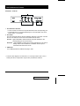
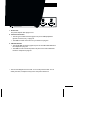
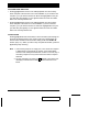
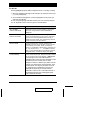
User Manual ACS-1712 ACS-1714 2001-07-05 NOTE: This equipment has been tested and found to comply with the limits for a Class B digital device pursuant to Subpart J of Part 15 of the FCC Rules. These limits are designed to provide reasonable protection against harmful interference in a residential installation. This equipment generates, uses and can radiate radio frequency energy and, if not installed and used in accordance with the instructions, may cause harmful interference to radio communications. However, there is no guarantee that interference will not occur in a particular installation. If this equipment does cause harmful interference to radio or television reception, which can be determined by turning the equipment off and on, the user is encouraged to try to correct the interference by one or more of the following measures: M Reorient or relocate the receiving antenna. M Increase the separation between the equipment and receiver. M Connect the equipment into an outlet on a circuit different from that which the receiver is connected. M Consult the dealer or an experienced radio/television technician for help. 2001-07-05 Packing List The complete Master View ACS-1712 / ACS-1714 package consists of: M One ACS-1712 or ACS-1714 KVM Switch M One Power Adapter M One User Manual Check to make sure that the unit was not damaged in shipping. If you encounter a problem, contact your dealer. Read this manual thoroughly and follow the installation and operation procedures carefully to prevent any damage to the unit, and/or any of the devices connected to it. ©Copyright 2000 ATEN International Co., Ltd. Manual Part No. PAPE-0185-100 Printed in Taiwan 06/2001 All brand names and trademarks are the registered property of their respective owners. ACS-1712 / ACS-1714 User Manual iii. 2001-07-05 Contents Overview . . . . . . . . . . . . . . . . . . . . . . . . . . . . . . . . . . . . . . . . . . . . . . . . . . . . . . 1 Features . . . . . . . . . . . . . . . . . . . . . . . . . . . . . . . . . . . . . . . . . . . . . . . . . . . . . . . 2 Hardware Requirements . . . . . . . . . . . . . . . . . . . . . . . . . . . . . . . . . . . . . . . . . . 3 Console . . . . . . . . . . . . . . . . . . . . . . . . . . . . . . . . . . . . . . . . . . . . . . . . . . . . 3 PC . . . . . . . . . . . . . . . . . . . . . . . . . . . . . . . . . . . . . . . . . . . . . . . . . . . . . . . . 3 Cables . . . . . . . . . . . . . . . . . . . . . . . . . . . . . . . . . . . . . . . . . . . . . . . . . . . . . 3 Introduction . . . . . . . . . . . . . . . . . . . . . . . . . . . . . . . . . . . . . . . . . . . . . . . . . . . . 4 Front View . . . . . . . . . . . . . . . . . . . . . . . . . . . . . . . . . . . . . . . . . . . . . . . . . . 4 Rear View. . . . . . . . . . . . . . . . . . . . . . . . . . . . . . . . . . . . . . . . . . . . . . . . . . . 5 Installation . . . . . . . . . . . . . . . . . . . . . . . . . . . . . . . . . . . . . . . . . . . . . . . . . . . . . 6 Before you Begin . . . . . . . . . . . . . . . . . . . . . . . . . . . . . . . . . . . . . . . . . . . . . 6 Cable Connection. . . . . . . . . . . . . . . . . . . . . . . . . . . . . . . . . . . . . . . . . . . . . 6 Operation . . . . . . . . . . . . . . . . . . . . . . . . . . . . . . . . . . . . . . . . . . . . . . . . . . . . . . 7 Hot Plugging. . . . . . . . . . . . . . . . . . . . . . . . . . . . . . . . . . . . . . . . . . . . . . . . . 7 Powering Off and Restarting . . . . . . . . . . . . . . . . . . . . . . . . . . . . . . . . . . . . 8 Port Selection. . . . . . . . . . . . . . . . . . . . . . . . . . . . . . . . . . . . . . . . . . . . . . . . 8 Port ID Numbering . . . . . . . . . . . . . . . . . . . . . . . . . . . . . . . . . . . . . . . . . . . . . . . 9 CPU ID Numbering . . . . . . . . . . . . . . . . . . . . . . . . . . . . . . . . . . . . . . . . . . . 9 USB ID Numbering . . . . . . . . . . . . . . . . . . . . . . . . . . . . . . . . . . . . . . . . . . . 9 Hotkey Summary Table . . . . . . . . . . . . . . . . . . . . . . . . . . . . . . . . . . . . . . . 10 OSD Operation . . . . . . . . . . . . . . . . . . . . . . . . . . . . . . . . . . . . . . . . . . . . . . . . 11 OSD Overview . . . . . . . . . . . . . . . . . . . . . . . . . . . . . . . . . . . . . . . . . . . . . . 11 OSD Navigation . . . . . . . . . . . . . . . . . . . . . . . . . . . . . . . . . . . . . . . . . . . . . 12 OSD Main Menu Headings . . . . . . . . . . . . . . . . . . . . . . . . . . . . . . . . . . . . 13 The Function Keys . . . . . . . . . . . . . . . . . . . . . . . . . . . . . . . . . . . . . . . . . . . 13 Factory Default Settings. . . . . . . . . . . . . . . . . . . . . . . . . . . . . . . . . . . . . . . 16 OSD Security . . . . . . . . . . . . . . . . . . . . . . . . . . . . . . . . . . . . . . . . . . . . . . . 17 Appendix . . . . . . . . . . . . . . . . . . . . . . . . . . . . . . . . . . . . . . . . . . . . . . . . . . . . . 18 Troubleshooting . . . . . . . . . . . . . . . . . . . . . . . . . . . . . . . . . . . . . . . . . . . . . 18 Specifications . . . . . . . . . . . . . . . . . . . . . . . . . . . . . . . . . . . . . . . . . . . . . . . 19 Limited Warranty . . . . . . . . . . . . . . . . . . . . . . . . . . . . . . . . . . . . . . . . . . . . 20 iv. ACS-1712 / ACS-1714 User Manual 2001-07-05 Overview The Master View ACS-1712 and ACS-1714 represent a revolutionary new direction in KVM (Keyboard, Video, Mouse) Switches. The ACS-1712 and ACS-1714 are dual function two and four Port KVM Switches combined with 2 Port USB Hubs. As KVM switches, they allow users to access two and four computers from a single USB keyboard, USB mouse, and monitor console, using USB technology to handle the keyboard and mouse data transfer between the switch and the connected computers. With it’s independent switching feature, the ACS-1712 / ACS-1714 allows each of the computers to utilize the USB connection to the switch in order to access two USB peripheral devices on a ‘one computer at a time’ basis. This innovative feature makes it possible, for example, for a user to work on one computer while printing from a second computer at the same time. As a result, the ACS-1712 / ACS-1714 offers considerable savings. Since the KVM Switch - USB Port combination functions as a USB Hub, it allows two (ACS-1712 ) or four (ACS-1714 ) computers to access and share all the connected USB peripherals. Not only does this eliminate the need to purchase a separate USB hub, it also eliminates the need to purchase separate stand-alone peripheral sharers - such as print servers, modem splitters, etc. There are three convenient methods to access the computers: (1) push button port selection switches located on the unit’s front panel; (2) Hotkey combinations; and (3) selecting from menus provided by the OSD (On Screen Display) feature. Setup is fast and easy; simply plug cables into their appropriate ports. The computers recognize the USB peripherals the first time they come in contact with them and automatically install the necessary drivers. There is no software to configure, no installation routines, and no incompatibility problems. Since the ACS-1712 / ACS-1714 intercepts keyboard input directly, it works on any hardware platform and with all operating systems. There is no better way to save time and money than with a Master View ACS-1712 / ACS-1714 installation. Since a single console manages all of the computers, the ACS-1712 / ACS-1714 setup: eliminates the expense of having to purchase a separate keyboard, monitor, and mouse for each computer; saves all the space those extra components would take up; saves on energy costs; and eliminates the inconvenience and wasted effort involved in constantly moving around from one computer to another. ACS-1712 / ACS-1714 User Manual 1 2001-07-05 Features M Dual Function KVM-USB Switch M One Console Controls 2 (ACS-1712 ) or 4 (ACS-1714 ) Computers and Two Additional USB Devices M USB Keyboard and Mouse M Independent Switching of KVM and Additional USB Ports - Control one Computer while Printing From a Second Computer at the Same Time M Fully Compliant with the USB 1.1 Specification M OSD and LED Display For Easy Status Monitoring M Easy Installation - No Software Required, Computer Selection via Front Panel Switches, Hotkeys, or OSD (On Screen Display) M Auto Scan Mode for Monitoring All Computers M Complete Keyboard and Mouse Emulation for Error Free Booting and Real Time Switching M Superior Video Quality;1920x1440; DDC2B M Hot Pluggable - Add or Remove Computers for Maintenance Without Powering Down the Switch M Supports both Wintel & Mac Host Systems (USB Enabled only) M Windows 98SE, WIN ME, Win2000, Mac OS8.5 or higher 2 ACS-1712 / ACS-1714 User Manual 2001-07-05 Hardware Requirements Console M A VGA, SVGA, or Multisync monitor capable of the highest resolution that you will be using on any computer in the installation. M A USB style mouse M A USB style keyboard Computer The following equipment must be installed on each computer: M A VGA, SVGA or Multisync card. M Type A USB port. Cables Use of substandard cables may damage the connected devices or degrade overall performance. For optimum signal integrity and to simplify the layout, we strongly recommend that you use the following high quality CS cables: M Part No. 2L-1201U [1.2M]; or M Part No. 2L-1202U [1.8m]. ACS-1712 / ACS-1714 User Manual 3 2001-07-05 Introduction Front View* 1 2 3 1. Port Selection Switches M Press a switch to access the computer attached to the corresponding port. M Pressing Buttons 1 and 2 simultaneously for 2 seconds starts Auto Scan Mode. See p. 14 for details. 2. Port LEDs The Port LEDs are built into the Port Selection Switches. The upper ones are the On Line LEDs; the lower ones are the Selected Port LEDs: On Line: Lights ORANGE to indicate that the computer attached to the corresponding port is up and running. Selected: Lights GREEN to indicate the currently selected port. The LED is steady under normal conditions, but flashes when its port is accessed under Auto Scan mode. 3. USB Ports Your USB keyboard and USB mouse plug in here. * The front view diagram is for the ACS-1714. The layout of the ACS-1712 is exactly the same, except that it only has two port selection switches. 4 ACS-1712 / ACS-1714 User Manual 2001-07-09 Rear View* 1. Power Jack The power adapter cable plugs in here. 2. Console Port Section M The two type A USB connectors (upper row) are for USB peripherals (printers, scanners, etc.), to plug into. M The HDB-15 female connector is for your monitor to plug into. 3. CPU Port Section M The type B USB connectors (upper row) are for the USB cables that link to the computers to plug into. M The HDB-15 male connectors (bottom row) are for the video cables that link to the computers to plug into. * The rear view diagram is for the ACS-1714. The layout of the ACS-1712 is exactly the same, except that it only has 2 CPU ports instead of 4. Installation Before you Begin 1. Make sure that power to all the devices you will be connecting up have been turned off. You must unplug the power cords of any computers that have the Keyboard Power On function. Otherwise, the switch will still receive power from the computer. 2. To prevent damage to your equipment due to ground potential difference, make sure that all devices on the installation are properly grounded. Consult your dealer for technical details, if necessary. Cable Connection To set up your Master View ACS-1712 / ACS-1714 installation do the following: 1. Plug your USB keyboard and USB mouse into the USB Ports located on the unit’s front panel. 2. Plug your monitor into the Console monitor port located on the unit’s rear panel. 3. Plug the B end of a USB cable into any available CPU Section USB port; plug the A end of the cable into the computer you are connecting up. 4. Plug the female end of a video cable into the CPU Section video port that corresponds to the USB port you selected in step 3; plug the male end of the cable into the video port of the computer you are connecting up. 5. Repeat steps 3 and 4 for any other computers you are connecting up. 6. Plug the power adapter cable into the Master View’s Power Jack, then plug the power adapter into an AC power source. 7. Turn on the power to the computers. 6 ACS-1712 / ACS-1714 User Manual 2001-07-05 Operation Hot Plugging The Master View ACS-1712 / ACS-1714 supports USB hot plugging components can be removed and added back into the installation by unplugging their cables from the CPU ports without the need to shut the unit down. Powering Off and Restarting If it becomes necessary to Power Off the Master View unit, before starting it back up you must do the following: 1. Shut down all the computers that are attached to the unit. Note: 1. You must unplug the power cords of any computers that have the Keyboard Power On function that are connected to the shut down switches. Otherwise, the switches will still receive power from the computers. 2. If the unit is operating under external power, unplug the power adapter cable. 2. Wait 10 seconds, then plug the Master View ACS-1712 / ACS-1714 unit back in. 3. After the Master View unit is up, Power On the computers. ACS-1712 / ACS-1714 User Manual 7 2001-07-05 Port Selection The Master View ACS-1712 / ACS-1714 provides three methods to obtain instant access to any computer on your installation: Manual; Hotkey; and OSD. M Manual Simply press the appropriate Port Selection Switch on the Master View’s front panel. After you press the switch, the Selected LED lights to indicate that the port is currently selected. The OSD (see p. 11) automatically switches to highlight the computer that you have selected. M Hotkey Access Hotkeys allow you to select which computer is the active one - and/or which computer has access to the USB peripherals - directly from the keyboard, instead of having to manually do it with a Port Selection switch. Note: CPU Port selection and USB Port assignment can be done independently - one computer can have the CPU focus while another one has access to the USB peripherals. To utilize the Hotkey method, do the following: CPU Port Selection: 1. Press [Ctrl] + [Shift] + [Alt] to invoke the Hotkey function 2. Key in the CPU Port ID number (see Port ID Numbering, in the next section). USB Peripheral Port Assignment: Hotkeys can also be used to assign the USB peripheral ports to a particular computer as follows: 3. Press [Ctrl] + [Shift]+ [Alt] to invoke the Hotkey function 4. Key in the USB Port ID number (see Port ID Numbering, in the next section). Note: 1. Press the keys in sequence - one key at a time. First [Ctrl], then [Shift] then [Alt]. 2. After invoking the Hotkey function with the [Ctrl] + [Shift] + [Alt] combination, you must key in the corresponding Port ID within 1 second for each keypress. M OSD OSD (On Screen Display), provides a menu driven interface to handle computer and peripheral switching. OSD operation is discussed in detail beginning on page 11. 8 ACS-1712 / ACS-1714 User Manual 2001-07-05 Port ID Numbering CPU ID Numbering Each CPU port on a Master View installation is assigned a single digit number (1 or 2 for the ACS-1712; 1 to 4 for the ACS-1714). The Port ID of a computer is derived from the CPU Port number it is connected to. For example, a computer connected to CPU Port 3 has a Port ID of 3. You can directly access any computer on the installation by specifying its Port ID - either with the Hotkey port selection method, or from the OSD Main Menu. For Example: To access a computer attached to Port 2 with the Hotkey method, invoke the Hotkey function, then key in 2 for the Port ID, as follows: [Ctrl] + [Shift] + [Alt] + [2] Note: You must key in the sequence one key at a time. USB ID Numbering You can assign the two USB peripheral ports to any computer on the installation by specifying its USB ID - either with the Hotkey port selection method, or from the OSD Main Menu. The USB ID is derived from the Function key that corresponds to the computer’s Port ID. For example, if a computer’s Port ID is 3, its USB ID is F3. To give a computer attached to Port 3 access to the USB peripherals with the Hotkey method, invoke the Hotkey function, then key in F3 for the USB ID, as follows: [Ctrl] + [Shift] + [Alt] +[F3] Note: You must key in the sequence one key at a time. ACS-1712 / ACS-1714 User Manual 9 2001-07-05 Hotkey Summary Table Combination Action [Ctrl] + [Ctrl] Invokes OSD (Default) [Scroll Lock] + [Scroll Lock] Invokes OSD (Alternate Method) [Ctrl]+[Shift]+[Alt]+[1] Switches access to the computer that corresponds to Port ID number 1. [Ctrl]+[Shift]+[Alt]+[2] Switches access to the computer that corresponds to Port ID number 2. [Ctrl]+[Shift]+[Alt]+[3]* Switches access to the computer that corresponds to Port ID number 3. [Ctrl]+[Shift]+[Alt]+[4]* Switches access to the computer that corresponds to Port ID number 4. [Ctrl]+[Shift]+[Alt]+[0] Invokes Auto Scan mode. [Ctrl]+[Shift]+[Alt]+[F1] Switches access to the USB peripherals to computer [1] [Ctrl]+[Shift]+[Alt]+[F2] Switches access to the USB peripherals to computer [2] [Ctrl]+[Shift]+[Alt]+[F3]* Switches access to the USB peripherals to computer [3] [Ctrl]+[Shift]+[Alt]+[F4]* Switches access to the USB peripherals to computer [4] * Master View ACS-1714 only 10 ACS-1712 / ACS-1714 User Manual 2001-07-05 OSD Operation OSD Overview On Screen Display (OSD), provides a menu driven interface to handle the computer switching procedure. Although Hotkey switching still works, using OSD is a great deal more convenient. All operations start from the OSD Main Menu. To pop up the Main Menu, tap either Ctrl key twice. Note: 1. The keys must be on the same side (both left, or both right). 2. You can optionally change the Hotkey to the Scroll Lock key (see OSD Activating Hotkey under the F10 SET UP function on p.15), in which case you would press [Scroll Lock] twice. When you invoke the OSD, a screen similar to the one below appears: MAIN PN PC KVM 1 + ☞ 2 + 3 + JOSH 4 + JIMMY F1 PREV KVM F4 NEXT KVM USB WARREN ☞ F5 PREV USB NAME F8 NEXT USB TINA F9 AUTO SCAN F10 SET UP M The OSD always starts with the highlight bars at the last position selected no matter which selection method was used (Push Button Switches, Hotkeys or OSD. M The next two sections explain how to navigate using the OSD. ACS-1712 / ACS-1714 User Manual 11 2001-07-05 OSD Navigation M [Esc] cancels the current selection, or dismisses the current menu and moves back to the menu one level above. If you are at the highest menu level, it deactivates OSD. M To activate a CPU port, use the F1 and F4 keys to move the CPU Port Highlight Bar through the list. When you reach the port you want, press [Enter]. An icon of a pointing finger indicates which port is the active one. M To activate a peripheral USB port, use the F5 and F8 keys to move the USB Port Highlight Bar through the list. When you reach the port you want, press [Enter]. An icon of a pointing finger indicates which port is the active one. M After executing any action, you automatically go back to the menu one level above. Note: CPU Port access andUSB peripheral access can be assigned independently. One computer can have the console focus while another one has access to the USB peripherals. 12 ACS-1712 / ACS-1714 User Manual 2001-07-05 OSD Main Menu Headings Heading Explanation PN This column lists the Port ID numbers for all the CPU ports on the installation. The simplest method to access a particular computer is move the Highlight Bar to its corresponding port, then press [Enter]. PC Lists all the computers that are Powered On and are On Line. KVM A ‘pointing finger’ icon in this column indicates which computer has the console focus. USB A ‘pointing finger’ icon in this column indicates which computer has access to the USB peripherals. NAME If a port has been given a name (see F10, below), its name appears in this column. The Function Keys Pressing Function Keys provide a means to control and configure the OSD. For example, you can: rapidly switch to any port; scan selected ports; limit the list you wish to view; create or edit a port name; or make OSD setting adjustments. F1-F4 PREV KVM / NEXT KVM M Pressing [F1] Switches console focus from the currently active computer to the Previous one on the installation. If you are at the first computer, you cycle back to the last one. Move the Highlight Bar to the port you want then press [Enter]. An icon appears before the choice to indicate that it is the currently selected one. M Pressing [F4] Switches console focus from the currently active computer to the Next one on the installation. If you are at the last computer, you cycle back to the first one. Move the Highlight Bar to the port you want then press [Enter]. An icon appears before the choice to indicate that it is the currently selected one. ACS-1712 / ACS-1714 User Manual 13 2001-07-05 F5-F8 PREV USB / NEXT USB M Pressing [F5] Switches access to the USB peripherals from the currently active computer to the Previous one on the installation. If you are at the first computer, you cycle back to the last one. Move the Highlight Bar to the port you want then press [Enter]. An icon appears before the choice to indicate that it is the currently selected one. M Pressing [F8] Switches access to the USB peripherals from the currently active computer to the Next one on the installation. If you are at the last computer, you cycle back to the first one. Move the Highlight Bar to the port you want then press [Enter]. An icon appears before the choice to indicate that it is the currently selected one. F9 AUTO SCAN Pressing [F9] initiates Auto Scan Mode, in which the OSD cycles through all the ports and displays them on the monitor. Each port is displayed for the amount of time set with the Scan Duration setting under the F10 SET UP function (see p.15 ). When you want to stop at a particular location, press the [Spacebar] to stop scanning. Note: 1. If the scanning stops on an empty port, or one where the computer is attached but is powered Off, the monitor screen will be blank, and the mouse and keyboard will have no effect. To recover, key in the Hotkey sequence for any Port ID that has an active computer attached. 2. As each computer is accessed, an S appears in front of the Port ID display to indicate that it is being accessed under Auto Scan Mode. 14 ACS-1712 / ACS-1714 User Manual 2001-07-05 F10 SET UP Pressing [F10] brings up the OSD configuration menu. To change a setting: 1. Move the highlight bar through the list using the Up and Down Arrow keys (↑↓), then press [Enter]. 2. On the submenu that appears, move the highlight bar to the choice you want and press [Enter]. An icon of a pointing finger indicates which choice is the currently selected one. An explanation of the choices is given in the table below: Setting Function SET CHANNEL DISPLAY DURATION Determines how long a Port ID displays on the monitor after a port change has taken place: 3 Seconds; or Always On. SET CHANNEL DISPLAY POSITION Allows you to position where the Port ID appears on the screen. Use the Arrow Keys, Pg Up, Pg Dn, Home, End, and 5 (on the numeric keypad with Num Lock off), to position the Port ID display, then press [Enter] to lock the position and return to the Set submenu. EDIT PC NAME To help remember which computer is attached to a particular port, every port can be given a name. The Edit function allows you to create, modify, or delete port names. Any combination of alphanumeric characters (a-z, A-Z, 0-9), as well as the + - / : , and Space characters. When you have finished editing, press [Enter] to have the change take effect. To abort the change, press [Esc]. LOCK CONSOLE Locks / Unlocks the Console. When the Console is locked, only the current monitor screen displays. A zzz appears in the top right corner of the OSD window to indicate that the console is locked. Attempts to input information from the console have no effect; attempts to switch to a different port, either from the Console or by pressing the manual switches, have no effect either. The only way to regain access to the computers is by Unlocking the Console. If a password has been set,you must provide the password in order to Lock / Unlock the Console. If no password has been set, pressing [Enter] will Lock / Unlock the Console. ACS-1712 / ACS-1714 User Manual 15 2001-07-05 Setting Function SET PASSWORD Allows you to set a password in order to control access to the console. See OSD Security (p. 17) for password setting details. SET SCAN DURATION Determines how long the display dwells on each port as it cycles through the selected ports in Auto Scan Mode. The options are: 3, 5, 10, 15, 20, 30, 40, and 60 seconds. SET OSD ACTIVATING HOTKEY Selects which Hotkey activates the OSD function: [Ctrl] [Ctrl] or [Scroll Lock] [Scroll Lock]. The default is the Ctrl key combination, but this may conflict with programs running on the computers, in which case, the Scroll Lock option should be used. Factory Default Settings The factory default settings are as follows: Setting Default Display Duration Always On Display Mode The Port Number plus the Port Name Scan Duration 5 Seconds 16 ACS-1712 / ACS-1714 User Manual 2001-07-05 OSD Security In order to prevent unauthorized access to the computers, the OSD provides a password security feature. If a password has been set, the OSD will request that the user specify it before allowing entry. To set a password: 1. Press [F10] to bring up the SET UP configuration menu. 2. Move the highlight bar to PASSWORD, then press [Enter]. 3. Key in the new password, then press [Enter]. The password may be up to 8 characters long, and can consist of any combination of letters and numbers (A - Z, 0 - 9). 4. Key in the new password again, in order to confirm that it is correct, then press [Enter]. If the two entries match, the new password is accepted and the screen displays the following message: SET PASSWORD OK If the entries do not match, the screen displays the message: PASSWORD NOT MATCH in which case you must start again from the beginning. Note: To modify or delete a previous password, access the Password function as in Steps 1 and 2, then use the backspace or delete key to erase the individual letters or numbers. ACS-1712 / ACS-1714 User Manual 17 2001-07-05 Appendix Troubleshooting Symptom Possible Cause Action Erratic behavior. Unit not receiving enough power under self-powered operation. Use the Power Adapter that was supplied with the unit to provide external power. Pressing Hotkeys gets no response. The connection from the selected port to the target computer has been broken. Check the cables to make sure they are all properly connected. Improper keyboard reset. Unplug the keyboard connector from the Console Keyboard Port, then plug it back in. Improper Master View reset. Power off the Master View unit; wait five seconds; then turn it back on. Incorrectly keying in the Port ID. After invoking the Hotkey function with the [Ctrl]+[Shift]+[Alt] combination, key in the Port ID and press [Enter] within one second for each keystroke. Improper mouse reset. Unplug the mouse connector from the Console Mouse Port, then plug it back in. Mouse not responding. 18 ACS-1712 / ACS-1714 User Manual 2001-07-05 Specifications Function ACS-1712 ACS-1714 Computer Connections 2 CPU Port Selection Front Panel Switches; Hotkeys; OSD USB Port Selection Hotkeys; OSD LEDs On Line 2 (Orange) 4 (Orange) Selected 2 (Green) 4 (Green) Keyboard 1 x USB Type A Mouse 1 x USB Type A Video 1 x HDB -15 female USB 2 x USB Type B 4 x USB Type B Video 2 x HDB -15 male 4 x HDB -15 male Console Connectors CPU Connectors 4 USB Peripherals 2 x USB Type A Emulation USB (Keyboard / Mouse) Scan Interval 3, 5, 10, 15, 20, 30, 40, 60 secs. Resolution Up to 1920 x 1440; DDC2B Power Consumption DC 5V; 0.85W max. DC 5V; 1.25W max. o Operating Temperature 5 - 40 C Storage Temperature -20 - 60o C Humidity 0 - 80% RH Housing Metal Weight 490g 700 g Dimensions (L x W x H) 130 x 74.5 x 42mm 200 x 74.5 x 42mm ACS-1712 / ACS-1714 User Manual 19 2001-07-05 Limited Warranty IN NO EVENT SHALL THE DIRECT VENDOR’S LIABILITY EXCEED THE PRICE PAID FOR THE PRODUCT FROM THE DIRECT, INDIRECT, SPECIAL, INCIDENTAL OR CONSEQUENTIAL DAMAGES RESULTING FROM THE USE OF THE PRODUCT, DISK OR ITS DOCUMENTATION. The direct vendor makes no warranty or representation, expressed, implied, or statutory with respect to the contents or use of this documentation, and specially disclaims its quality, performance, merchantability, or fitness for any particular purpose. The direct vendor also reserves the right to revise or update the device or documentation without obligation to notify any individual or entity of such revisions, or update. For further inquires please contact your direct vendor. 20 ACS-1712 / ACS-1714 User Manual 2001-07-05