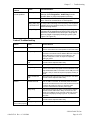
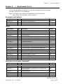
1
Operation & Service Manual 040-0207-01 Rev. A ¾ Read this manual before use. ¾ Keep this manual with the machine at all times. www.globalvr.com http://service.globalvr.com [email protected] Phone: 408.597.3435 Fax: 408.597.3437 © 2009 Global VR, Inc. GLOBAL VR and the GLOBAL VR logo are registered trademarks of Global VR, Inc. All Rights Reserved. JUSTICE LEAGUE and all related characters and elements are trademarks of and © DC Comics. (s09) Preface Table of Contents Preface ...................................................................4 Safety..................................................................4 Precautions for Game Operation.....................4 Warnings .........................................................4 Environmental Conditions ..............................4 FCC Notices (United States) ..............................5 Chapter 1 — Introduction..................................6 Game Features ................................................6 Current Requirements (Approximate) ............7 Hardware Features ..........................................7 Chapter 2 — Installing a New Cabinet..............8 Checking the Game Dongle ...............................9 Maintenance Restart Feature..............................9 Chapter 3 — Playing a Game ..........................10 Chapter 4 — Operator Menu and Game Setup .........................................................12 Navigating the Operator Menu.........................12 Machine Settings Menu....................................14 Machine Information Menu .............................15 Game Settings Menu ........................................16 Coin Settings Menu..........................................17 Statistics Screens ..............................................18 Diagnostics Menus ...........................................20 Controller Diagnostics Menu ........................21 Chapter 5 — Software Restoration..................22 Run the System Recovery Disk ....................22 Run the Game Install Disk ............................22 Chapter 6 — Service and Repair .....................23 Opening the Control Panel (42" Deluxe) .........23 Opening the Control Panel (26" Standard).......23 Control Panel Button Service...........................24 Joystick Service................................................24 Joystick Handle Replacement .......................24 Joystick Carriage, PCB, and Grommet Replacement ..............................................25 GVRI/O Mini PCB Service..............................26 Audio Speakers Service (42" Deluxe)..............27 Subwoofer Replacement (42" Deluxe).............27 America's Army Operation and Service Manual Page 2 of 52 Audio Speakers Service (26" Standard) .......... 27 LCD Monitor Service (42" Deluxe) ................ 27 LCD Monitor Replacement (42" Deluxe) .... 28 Glass Display Shield Replacement (42" Deluxe).............................................. 28 Monitor Power Supply Replacement (42" Deluxe).............................................. 28 LCD Monitor Service (26" Standard).............. 29 Glass Display Shield Replacement (26" Standard) ........................................... 29 LCD Monitor Replacement (26" Standard).. 29 Computer Replacement ................................... 30 Coin Mech Replacement ................................. 31 Coin Meter Replacement ................................. 31 Ventilation Fan Service.................................... 31 Power Distribution Service.............................. 32 AC Power Plate ............................................ 32 AC Power Strip Replacement....................... 32 +5/+12 VDC Power Supply Replacement ....... 33 Marquee Florescent Light Service (42" Deluxe).............................................. 33 Marquee Florescent Light Service (26" Standard) ........................................... 34 Florescent Light Fixture Replacement (Either Cabinet)......................................... 34 Cold-Cathode Florescent Light Service (42" Deluxe).............................................. 35 Setting the Computer BIOS (CMOS) .............. 36 Chapter 7 — Troubleshooting......................... 39 Video Troubleshooting ................................. 39 Audio Troubleshooting................................. 40 Control Troubleshooting............................... 41 Miscellaneous Troubleshooting.................... 42 Chapter 8 — Replacement Parts ..................... 43 Chapter 9 — Diagrams and Schematics ......... 47 Warranty Service ............................................. 51 LIMITED WARRANTY ................................. 51 Technical Support ............................................... 52 040-0207-01 Rev. A 2/24/2009 Preface List of Figures Figure 1. Cabinet Dimensions and Weights .......... 6 Figure 2. Coin Door with Key Location .............. 8 Figure 3. USB Game Dongle ............................... 9 Figure 4. 2-Player Game Screen ........................ 11 Figure 5. Operator Menu Flowchart .................. 13 Figure 6. Player Button and Micro Switch ........ 24 Figure 7. Joystick Exploded View ..................... 25 Figure 8. GVRI/O Mini PCB (Version 4) .......... 26 Figure 9. 26" Monitor Top Retaining Bracket ... 29 Figure 10. 26" Monitor Mounting Bracket ........ 30 Figure 11. Servicing the Coin Mech and Coin Meter......................................................... 31 040-0207-01 Rev. A 2/24/2009 Figure 12. AC Power Plate .................................32 Figure 13. Marquee Assembly (42" Deluxe)......34 Figure 14. 42" Deluxe Cabinet Artwork Part Numbers ....................................................45 Figure 15. 26" Standard Cabinet Artwork Part Numbers ....................................................46 Figure 16. Power Distribution Diagram .............47 Figure 17. Simplified Wiring Diagram...............48 Figure 18. Detailed Wiring Diagram ..................49 Figure 19. Computer Rear Panel Diagram .........50 ©2009 Global VR, Inc. Page 3 of 52 Preface Preface Safety Please read this page before preparing your arcade cabinet for game play. The following safety instructions apply to all game operators and service personnel. Specific warnings and cautions will be included throughout this manual. Use the following safety guidelines to help protect the system from potential damage and to ensure your personal safety: • Electronic components in the game cabinet run on 115 VAC. 230 VAC systems have a transformer to convert power to 115 VAC inside the cabinet. The voltage switch on the back of the computer must be set to 115. If you power up the computer outside of the cabinet, set the switch to match the local AC voltage: − 115 volts / 60Hz in most of North and South America and some Far Eastern countries such as Japan, South Korea and Taiwan − 230 volts / 50Hz in most of Europe, the Middle East and the Far East • To help prevent electric shock, plug the system into a properly grounded power source. These cables are equipped with 3-prong plugs to help ensure proper grounding. Do not use adapter plugs or remove the grounding prong from a cable. If you must use an extension cable, use a 3-wire cable with properly grounded plugs. • To help protect your system from sudden increases and decreases in electrical power, use a surge suppressor, line conditioner or Uninterruptible Power Supply (UPS). • Be sure nothing rests on the system's cables and that the cables are not located where they can be stepped on or tripped over. • Keep your system far away from radiators and other heat sources. • Do not block cooling vents. • Do not place the game in an area where a water jet would be used or use a water jet to clean the game. Precautions for Game Operation GLOBAL VR® assumes no liability for injuries incurred while playing our games. Operators should be aware that certain health and physical conditions may make people susceptible to injury when playing video games, particularly when the game moves or creates a sense of motion. Warnings To avoid electrical shock, unplug the cabinet before performing installation or service procedures. If a power cord is damaged, it must be replaced by the equivalent power cord available from GLOBAL VR or your distributor. GLOBAL VR assumes no liability for any damages or injuries incurred while setting up or servicing the cabinet. Only qualified service personnel should perform installation or service procedures! Environmental Conditions Cabinet is intended for indoor use only. Be sure to keep the cabinet dry and maintain operating temperatures of 59°—86°F (15°—30°C). JUSTICE LEAGUE: HEROES UNITED Operation and Service Manual Page 4 of 52 040-0207-01 Rev. A 2/24/2009 Preface FCC Notices (United States) Electromagnetic Interference (EMI) is any signal or emission radiated in free space or conducted along power or signal leads, that endangers the functioning of radio navigation or other safety service, or that seriously degrades, obstructs, or repeatedly interrupts a licensed radio communications service. Radio communications services include, but are not limited to, AM/FM commercial broadcast, television, cellular services, radar, air-traffic control, pager, and Personal Communication Services (PCS). These licensed services, along with unintentional radiators such as digital devices (including computer systems) contribute to the electromagnetic environment. Electromagnetic Compatibility (EMC) is the ability of items of electronic equipment to function properly together in the electronic environment. While this computer system has been designed and determined to be compliant with regulatory agency limits for EMI, there is no guarantee that interference will not occur in a particular installation. If this equipment does cause interference with radio communications services, which can be determined by turning the equipment off and on, you are encouraged to try to correct the interference by one or more of the following measures: • Re-orient the receiving antenna. • Relocate the cabinet relative to the receiver. • Plug the game into a different outlet so that the computer and the receiver are on different branch circuits. If necessary, consult a Regulatory EMC representative of GLOBAL VR or an experienced radio/television technician for additional suggestions. You may find the FCC Interference Handbook, to be helpful. It is available from the U.S. Government Print Office, Washington, DC 20402. This device has been tested and complies with the limits for a Class A digital device pursuant to Part 15 of the FCC Rules. These limits are designed to provide reasonable protection against harmful interference when the equipment is operated in a commercial environment. This equipment generates, uses, and can radiate radio frequency energy. If not installed and used in accordance with the instruction manual, it may cause harmful interference with radio communications. Operation of this equipment in a residential area is likely to cause harmful interference, in which case you will be required to correct the interference at your own expense. Operation is subject to the following conditions: • This device may not cause harmful interference. • This device must accept any interference received, including interference that may cause undesired operation. 040-0207-01 Rev. A 2/24/2009 ©2009 Global VR, Inc. Page 5 of 52 Chapter 1 — Introduction Chapter 1 — Introduction GLOBAL VR and DC Comics™ deliver a brand new comic book adventure designed exclusively for the coin-op market. Players select and control their favorite hero from DC's JUSTICE LEAGUE to help stamp out the forces of evil that conspire against mankind. Conversion kits are available to convert old cabinets to JUSTICE LEAGUE™: Heroes United. Game Features • • • • • 2-player cooperative play Competitive play for points Signature Powers Moves 3 worlds each with 3 levels Staged difficulty level makes it easy for beginning and challenging for experienced players. Figure 1. Cabinet Dimensions and Weights JUSTICE LEAGUE: HEROES UNITED Operation and Service Manual Page 6 of 52 040-0207-01 Rev. A 2/24/2009 Chapter 1 — Introduction Current Requirements (Approximate) Voltage 115 VAC 42" Deluxe Cabinet Inrush Operating 8 Amps 5 Amps 4.5 Amps 3 Amps 230 VAC 4 Amps 2.5 Amps 1.5 Amps 3 Amps 26" Standard Cabinet Inrush Operating Hardware Features • • • • Dual-Core Processor NVIDIA® GeForce Graphics 1 Gigabyte RAM 49-Way Digital Joysticks 040-0207-01 Rev. A 2/24/2009 • • • 26" Standard or 42" Deluxe LCD Monitor Dramatic Lighting on Deluxe Cabinet Supports Dollar Bill Validator ©2009 Global VR, Inc. Page 7 of 52 Chapter 2 — Installing a New Cabinet Chapter 2 — Installing a New Cabinet Use the following procedure to set up your game: 1. Carefully remove the cabinet from the packaging, giving yourself plenty of space. Inspect the exterior for any damage. 2. Remove the keys from the coin return slot. Open the coin door to locate the second set of keys. Figure 2. Coin Door with Key Location 3. Locate the items listed below; they are usually in the coin vault: • System Recovery Disk • Operation & Service Manual (This Document) • Game Install Disk • AC Power Cord 4. Your game cabinet should arrive ready to play, but it is advisable to check inside in case any components have shifted or come loose during shipping. Remove the door from the back of the cabinet and verify that all components are securely mounted, and all cables and wires are securely connected. See Chapter 9 — Diagrams and Schematics, beginning on page 47, for wiring and connection diagrams. 5. 42" Deluxe Cabinets Only: If the Marquee Artwork and clear plastic were packed separately from the cabinet, please see Figure 13 on page 33 for a diagram of the marquee assembly. The marquee artwork is sandwiched between the large sheet of clear plastic and the small plastic wings at each side. It is attached to the marquee housing by 7 (seven) screws that screw into metal standoffs that screw into nuts behind the marquee housing. 6. Connect the AC power cord from the cabinet to a grounded (3-terminal) AC wall outlet. 7. Power ON the cabinet using the ON/OFF switch located on the lower rear of the cabinet. Verify that the game boots properly. 8. Once the Attract movie starts, play a game with both sets of controls to verify that everything works properly. 9. Enter the Operator Menu to set up pricing and other settings. See Chapter 4 for detailed information on using the Operator Menus to set up your game. JUSTICE LEAGUE: HEROES UNITED Operation and Service Manual Page 8 of 52 040-0207-01 Rev. A 2/24/2009 Chapter 2 — Installing a New Cabinet Checking the Game Dongle The cabinet uses a Game Dongle to activate the game software. If the dongle is missing, the game will not run. When a USB Game Dongle is installed and working properly, a red LED will illuminate inside the dongle. If the software does not recognize the Game Dongle, make sure the Dongle is connected properly, and then power cycle the cabinet. If the dongle comes out while the game is running, a NO DONGLE screen will appear the next time a START button is pressed. Re-install the dongle; there is no need to reboot the game. Note: The dongle supplied with the cabinet is specific to the game and software version. Future software upgrades may require a new dongle. Important: Some of your cabinet information is stored in the dongle, so if you replace your computer, remove the dongle and keep it with the cabinet. Figure 3. USB Game Dongle Maintenance Restart Feature To keep the software running optimally, the game must be restarted every 24 hours. For locations that turn their games off every day, no additional restarts are needed. For locations that leave their games turned on continuously, the software will automatically reboot the game once every 24 hours according to the following conditions: 1. If the game has been running continuously for at least 24 hours, and the game has been in Attract Mode for at least 15 minutes, then a screen like the following will be displayed: 2. The screen will count down for 30 seconds. If a user presses the START button, the screen will not appear again until the next time the Attract Mode has been running for 15 minutes. If nobody presses the START button, the game will shut down and restart, which will take about 2 minutes. 3. After the cabinet completes the Restart, the next Maintenance Restart will be scheduled for 24 hours later. If the initial Restart happens to be scheduled during a busy time for your location, the action of players pressing START to postpone will move the restart to a time that is not busy. 040-0207-01 Rev. A 2/24/2009 ©2009 Global VR, Inc. Page 9 of 52 Chapter 3 — Playing a Game Chapter 3 — Playing a Game This section describes the basics of starting and playing a game. 1. Coin up and press the START button. The Select Character screen will appear. Use the joystick to highlight the character you want to play and then press any button. 2. The Select Level screen will appear next. Use the joystick to highlight the level you want to play and then press any button. 3. Once the game starts, use the joystick to control your character's direction. 4. Press the QUICK (red) button to punch and STRONG (blue) to kick. Press DEFEND (green) to evade or shield your hero from attacks. 5. If you start a 1-Player Game, an onscreen prompt will be displayed during the game, inviting a second player to join, as shown in the picture to the right. 6. Watch the Health Meter! Once it runs out your character is vulnerable. Some enemies drop Health power-ups when defeated. 1-Player Game Screen 7. Press the Yellow+Red or Yellow+Blue buttons together to use Power Moves. (Each character has unique power moves.) You gain power each time you kick or punch an enemy. You can also pick up Power-Up Coins when you destroy explosive barrels or other objects, or defeat enemies carrying coins. More power in your Power Meter means your hero will inflict more damage on the enemies. JUSTICE LEAGUE: HEROES UNITED Operation and Service Manual Page 10 of 52 040-0207-01 Rev. A 2/24/2009 Chapter 3 — Playing a Game 8. As you play, your character's score, health, and power stats are displayed onscreen, as shown below. Each character's picture is displayed next to their stats. In the picture below, Superman has lots of power, but is low on health. Green Lantern is out of power but has more health than Superman. Figure 4. 2-Player Game Screen 040-0207-01 Rev. A 2/24/2009 ©2009 Global VR, Inc. Page 11 of 52 Chapter 4 — Operator Menu and Game Setup Chapter 4 — Operator Menu and Game Setup This chapter describes how to use the Game Operator menu to set up the game, diagnose problems, and view gameplay and earnings statistics. Navigating the Operator Menu Use the Operator buttons to navigate the Operator Menu as follows: • Use the Test/Back button to open the Operator menu. Once in the menu, use it to deselect an item or exit from a submenu. • Use the Up & Down buttons to move through a list and highlight items (a yellow box around an item indicates it is highlighted). Also use the Up & Down buttons to change the setting for a selected item. • Use the Service/Select button to select a highlighted item (a red box appears around a selected item) and to highlight and select the settings box for a highlighted item. For example, the following steps explain how to change the Attract Volume from the menus. 1. Press the Operator Test/Back button to open the Operator Menu. Machine Settings will be highlighted with a yellow box. 2. Press the Service/Select button to select the highlighted Machine Settings menu. 3. Press the Down button to highlight (yellow box) Attract Volume. 4. Press the Service/Select button twice. The first press highlights (yellow box) the settings box for Attract Volume; the second press selects (red box) the settings box. 5. With the settings box selected, press the Up and Down buttons to set the desired volume level. 6. Press Test/Back repeatedly until only Machine Settings, in the left menu, is highlighted. 7. Press the Up and Down buttons until Play Game is highlighted. 8. Press the Service/Select button to return to the game. Notes: To exit from some sub-menu screens, press the Down button to highlight Back to Main Menu, and then press Service/Select. Pressing the Service/Select button during Attract Mode adds a Service Credit that you can use for testing game play. You can disable or enable this feature from the Machine Settings menu. Pressing the Up or Down Operator buttons during Game or Attract Mode adjusts the Master Volume level. JUSTICE LEAGUE: HEROES UNITED Operation and Service Manual Page 12 of 52 040-0207-01 Rev. A 2/24/2009 Chapter 4 — Operator Menu and Game Setup Figure 5. Operator Menu Flowchart 040-0207-01 Rev. A 2/24/2009 ©2009 Global VR, Inc. Page 13 of 52 Chapter 4 — Operator Menu and Game Setup Machine Settings Menu This menu lets you set audio volume levels, enable or disable the Service Credit Switch, and restore factory default settings. Figure 1. Menu Item Machine Settings Menu Description Master Volume Sets the Master Volume level from 0 to 100. (Same as using the UP/DOWN buttons on the Operator button panel during Game or Attract Mode.) Attract Volume Sets Attract Mode volume level as a percentage of Master volume. Service Credit Switch Sets Service Credit Switch to Enabled or Disabled. If Enabled, the Service/Select button on the Operator button panel can be used to add Service Credits for testing gameplay. Factory Default Selecting Restore Factory Default restores all Game Settings to factory defaults. A popup window will appear describing exactly what will be reset, and giving you the option to press Service/Select to proceed or Test/Back to cancel. JUSTICE LEAGUE: HEROES UNITED Operation and Service Manual Page 14 of 52 040-0207-01 Rev. A 2/24/2009 Chapter 4 — Operator Menu and Game Setup Machine Information Menu This screen displays information about the hardware and software, and the maintenance restart. Figure 2. Menu Item Machine Information Menu Description Country Displays the country of operation as set by the game dongle. Cabinet Type Displays the type of cabinet, as set by the game dongle. Game Version Displays the Game Software version. OS Version Displays the Operating System version. I/O Board 1 Displays the version of the I/O PCB in the cabinet. Last Power Cycle Displays the time, in days, hours and minutes, since the cabinet was last powered on. Previous Maintenance Restart Displays the time, in days, hours and minutes, since the last maintenance restart. (A maintenance restart will only occur if the cabinet is not powered off for 24 hours. See page 9 for more information.) Note: If the screen displays 999 Days, this indicates that no maintenance restart has occurred because the cabinet has been powered off every day. Next Maintenance Restart Displays the time, in hours and minutes, until the next maintenance restart. If the cabinet is powered off, this time resets to 24 hours. 040-0207-01 Rev. A 2/24/2009 ©2009 Global VR, Inc. Page 15 of 52 Chapter 4 — Operator Menu and Game Setup Game Settings Menu This screen lets you set game difficulty and minimum time, and set whether to save and display high scores. Figure 3. Menu Item Game Settings Menu Description Difficulty Sets the overall game difficulty. Options are Easy, Normal, and Hard. Minimum Game Time Sets the amount of gameplay time that a player is guaranteed per start. (Range is 2—5 minutes.) Enable High Scores If Enabled, players can enter their names when they get a high score, and the high scores are displayed during Attract Mode. If Disabled, no High Scores are displayed and players are not prompted to enter a name when they get a high score. Reset High Scores Select the Reset? button, and then press Service/Select again when prompted to confirm, to reset the high scores displayed in Attract Mode to default values. JUSTICE LEAGUE: HEROES UNITED Operation and Service Manual Page 16 of 52 040-0207-01 Rev. A 2/24/2009 Chapter 4 — Operator Menu and Game Setup Coin Settings Menu This screen lets you set up pricing and displays available paid and service credits. Figure 4. Coin Settings Menu Menu Item Description Insert Display Selects the money display prompt text displayed onscreen. Options are Insert Credits or Swipe Card. Coin 1 Cred / Pulse Sets the number of credits per pulse for Coin Mech 1 (coins) Coin 2 Cred / Pulse Sets the number of credits per pulse for Coin Mech 2 (bills) Available Paid Credits Displays the number of available paid credits. Available Service Credits Displays the number of available service credits (added using the Service button on the Operator Button panel). Free Play Turns Free Play On or Off. Credits to Start Sets the number of credits to start a new game. Credits to Continue Sets the number of credits to continue a game. Reset Available Credits Select Reset Credits?, and then press Service/Select again when prompted to confirm, to clear all available credits. 040-0207-01 Rev. A 2/24/2009 ©2009 Global VR, Inc. Page 17 of 52 Chapter 4 — Operator Menu and Game Setup Statistics Screens The Statistics screens allow the operator to view the statistics collected by the cabinet. To reset the statistics for any screen, highlight the Reset button onscreen and press Service/Select. A popup window will appear describing exactly what will be reset, and giving you the option to press Service/Select to proceed or Test/Back to cancel. Statistics Main Menu allows you to select from the following: Coin Stats to view or reset earnings data Machine Stats, to view or reset gameplay data Game Stats to view or reset game level, character play, and score data Coin Stats displays the collection data for the cabinet. Coin 1 (Coins): Credits earned from Coin Mechs Coin 2 (Bills): Credits earned from Bill Validator Service Credits: Service Credits used Reset Coin Statistics: Select Reset? to clear current coin statistics. Lifetime totals are never reset unless the operating system is restored using the System Recovery Disk. Lifetime Paid Credits: Total Paid Credits earned for the lifetime of the cabinet Lifetime Service Credits: Total Service Credits used for the lifetime of the cabinet JUSTICE LEAGUE: HEROES UNITED Operation and Service Manual Page 18 of 52 040-0207-01 Rev. A 2/24/2009 Chapter 4 — Operator Menu and Game Setup Machine Stats displays player starts and length of play statistics. Player 1 Starts: Number of Player 1 starts P1 Continues: Number of times Player 1 has continued a game Player 2 Starts: Number of Player 2 starts P2 Continues: Number of times Player 2 has continued a game Average Play Time: Average time a game lasts Shortest Play Time: Shortest play time recorded Longest Play Time: Longest play time recorded Reset Machine Stats: Select Reset? to clear all statistics displayed on this screen Game Stats displays detailed statistics about the game levels played, plus average and high scores. Avg Score: Average of all scores High Score: Highest score recorded Campaign x Selected: Displays the number of times each campaign has been selected for play Character Selected: Displays the number of times each character has been selected for play Reset Game Stats: Select Reset? to clear all statistics displayed on this screen 040-0207-01 Rev. A 2/24/2009 ©2009 Global VR, Inc. Page 19 of 52 Chapter 4 — Operator Menu and Game Setup Diagnostics Menus The Diagnostics menus allow the operator to adjust video appearance, and test audio, game controls, and coin inputs. Diagnostics Main Menu allows you to select from the following: Visual Diagnostics to adjust monitor brightness, contrast or gamma, and display monitor test screens Audio Diagnostics to test left and right audio output Controller Diagnostics to test game controls and coin inputs Visual Diagnostics allows you to adjust the image quality on the monitor. Gamma: Adjusts the overall brightness of the image in a different way than the Brightness setting. If your image is not bright enough, you can experiment with Gamma and Brightness settings to see which has the best effect. Contrast: Adjusts the monitor contrast levels Brightness: Adjusts the monitor brightness levels Test Screens: Select Show Test Screens to open a series of monitor test screens (see examples below) designed to help you adjust the image using the Monitor Remote Control. Press the Service/Select button repeatedly to cycle through the screens. Examples of Monitor Test Screens: JUSTICE LEAGUE: HEROES UNITED Operation and Service Manual Page 20 of 52 040-0207-01 Rev. A 2/24/2009 Chapter 4 — Operator Menu and Game Setup Audio Diagnostics allows you to test the left and right speakers individually. Highlight Test Left Speaker and press Service/Select to hear a test sound from the left speaker only. Highlight Test Right Speaker and press Service/Select to hear a test sound from the right speaker only. To repeat the test sound, press Service/Select again. Press Up or Down to select the other speaker. Controller Diagnostics Menu This menu displays an image of the Player 1 and Player 2 controls to allow you to test the joysticks and buttons. You can also assign which joystick is used for each player in case they get swapped. You can also test the coin and bill inputs. Figure 5. Controller Diagnostics Menu When you move a joystick, the joystick center-point in the picture will move in the direction of joystick movement if the joystick is working properly. When you press a button or activate a coin mech (Coin 1) or the bill validator (Coin 2) the corresponding item will be highlighted onscreen. Select Assign Player Joysticks, and press Service/Select if the joysticks should happen to get swapped. When prompted, press the START button for Player 1, and then for Player 2 to reassign each joystick to the correct control set. 040-0207-01 Rev. A 2/24/2009 ©2009 Global VR, Inc. Page 21 of 52 Chapter 5 — Software Restoration Chapter 5 — Software Restoration Follow the instructions below if you need to re-install software on your cabinet. Total installation time is about 20 minutes. Note: On 26" Standard Cabinets the easiest way to reach the DVD-ROM drive is probably to open the control panel as described on page 23. You may also be able to reach the drive through the coin door. Important: When you use the System Recovery Disk, you will erase all game settings and coin and game statistics. It is advisable to contact Technical Support before using the System Recovery Disk to resolve a problem. Run the System Recovery Disk 1. With the cabinet powered ON, open the DVD-ROM drive and insert the CD labeled System Recovery Disk. Power the cabinet OFF and then ON. The computer will boot from the CD, and you will see a series of screens as the computer copies files to the hard drive. 2. After about 4-5 minutes, when you are prompted, remove the CD and turn the cabinet OFF and then ON. (Do not insert the Game Install Disk yet!) 3. When the computer reboots, you will see a series of processing screens. After about 5 minutes the computer will automatically reboot. After another minute you will see a message saying "Please insert Justice League Game Disk number 1." Proceed to run the Game Install Disk as described below. Run the Game Install Disk 1. Open the DVD-ROM drive and insert the DVD labeled Game Install Disk 1 of 1. The computer will read the DVD automatically (do not reboot). You will see the Installer screen as the software copies files, and after about 7 minutes the computer will reboot. 2. After about 2 minutes more, the Attract Mode will start. Remove the disk from the drive. Keep the disks in a safe place in case you need them in the future. 3. Use the Operator Menus to set pricing and change any desired settings. 4. Play a game and use both sets of controls to verify proper operation. (If the Service Credit Switch is enabled, press the Service/Select button in Attract Mode to insert Service Credits for testing the game.) JUSTICE LEAGUE: HEROES UNITED Operation and Service Manual Page 22 of 52 040-0207-01 Rev. A 2/24/2009 Chapter 6 — Service and Repair Chapter 6 — Service and Repair CAUTION: GLOBAL VR assumes no liability for any damage or injuries incurred while servicing the cabinet. Only qualified service personnel should perform service and installation of cabinet hardware. To prevent electrostatic discharge (ESD) damage, handle PCBs by the edges only and use a grounding wrist strap or similar precaution. Please read the service instructions before working on the cabinet. Always turn the cabinet OFF and disconnect the AC power cord before performing any repair work. Opening the Control Panel (42" Deluxe) Open the control panel to service the joysticks, buttons, and control panel CCFLs. Each side of the control panel has a base cover held in place by four nuts and bolts. Reach through the coin door to remove the four nuts and remove the cover. The figure below shows the locations of the nuts and bolts. Figure 6. Opening Control Panel (42" Deluxe) Opening the Control Panel (26" Standard) Open the control panel to service the joysticks and buttons, and to access the GVRI/O Mini PCB. To open the control panel, remove the five (5) Torx security screws from the control panel surface. Being careful not to pull any wires, tilt the control panel back and lean it against the cabinet. The control panel is not on a hinge. 040-0207-01 Rev. A 2/24/2009 ©2009 Global VR, Inc. Page 23 of 52 Chapter 6 — Service and Repair Control Panel Button Service Figure 6 shows a control panel button and micro switch, and which micro switch spade connects to each wire. Perform the following steps to replace the micro switches or the buttons: 1. Open the control panel as described in the previous sections. 2. Gently press the plastic micro switch to the side to release it from the button housing. 3. Disconnect the two wires from the micro switch and connect them to the new micro switch. Be sure to connect the ground wire to the COM connector and the signal wire to the NO connector, as shown in Figure 6. 4. To remove the button, unscrew the retaining ring. 5. Reverse these steps to install the replacement button and micro switch. Figure 6. Player Button and Micro Switch Joystick Service Joystick Handle Replacement Refer to Figure 7 on page 25 for an exploded-view drawing of joystick components. 1. Open the Control Panel as described on page 23. 2. Remove the E-clip from the bottom of the joystick assembly and pull the joystick handle out through the top of the control console. The lower shaft spacer will be loose under the joystick assembly, and the small upper spacer will remain on the joystick handle. 3. Place the small upper spacer on the new joystick handle and insert the handle into the control panel and through the lower shaft spacer. 4. Re-install the E-clip on the bottom of the joystick assembly. 5. After servicing a joystick, select Diagnostics: Controller Diag from the Operator Menu to verify proper operation (see page 21). JUSTICE LEAGUE: HEROES UNITED Operation and Service Manual Page 24 of 52 040-0207-01 Rev. A 2/24/2009 Chapter 6 — Service and Repair Joystick Carriage, PCB, and Grommet Replacement Refer to Figure 7 for an exploded-view drawing of joystick components. CAUTION: To prevent electrostatic discharge (ESD) damage, handle PCBs by the edges only and use a grounding wrist strap or similar precaution. 1. Disconnect the game from AC power and open the Control Panel as described on page 23. 2. Disconnect the cable from the joystick. 3. Remove the four Phillips screws from the joystick carriage. Note: Do not loosen the four hex nuts that secure the hub to the control panel. 4. Remove the joystick carriage, PCB, and L-stop. Note the orientation of the PCB so you can reinstall it the same way. 5. To remove the grommet, first remove the joystick handle as described in the previous section, and then remove the four Phillips screws that secure the grommet to the hub. Note: If you need to replace the hub, you will have to remove all buttons and screws from the top of the control panel, and then remove the plastic overlay to access the screws that secure the hub to the console. 6. Reverse these steps to re-install the joystick components. 7. After servicing a joystick, select Diagnostics: Controller Diag from the Operator Menu to verify proper operation (see page 21). Handle L-Stop Upper Spacer PCB Hub Carriage Grommet #8x1-3/4 Phillips Screws #8x3/4 Sheet Metal Phillips Screws E-Clip Lower Spacer Figure 7. Joystick Exploded View 040-0207-01 Rev. A 2/24/2009 ©2009 Global VR, Inc. Page 25 of 52 Chapter 6 — Service and Repair GVRI/O Mini PCB Service Important: This game requires game-specific GVRI/O Mini PCB firmware version 4.32 or later. If you replace the PCB with the wrong firmware version the game will not work properly. To verify the firmware version, open the Machine Information screen in the Operator Menu and check the number displayed for IO Board 1. (The initial release displays 4.50 in the Operator Menu.) The GVRI/O MINI PCB relays signals between the system computer and the hardware. Each connector on the GVRI/O MINI PCB is keyed to fit only to the correct harness connector. Refer to Figure 8 to locate the connectors on the PCB. See Figure 18 for detailed wiring information. The GVRI/O MINI PCB should always be connected to a PCI USB port, not a motherboard USB port, to minimize the possibility of static shock. No jumpers are used with this game. Figure 8. GVRI/O Mini PCB (Version 4) Perform the following steps to replace the GVRI/O Mini PCB: CAUTION Disconnect the cabinet from AC power before changing any connections to the GVRI/O MINI PCB. To prevent electrostatic discharge (ESD) damage, handle PCBs by the edges only and use a grounding wrist strap or similar precaution. 1. Disconnect the cabinet AC Power Cord. 2. 42" Deluxe Cabinets: Open the coin door. The PCB is mounted to an interior cabinet wall. 26" Standard Cabinets: The PCB is located on a shelf below the control panel. You can reach it by opening the control panel as described on page 23 or removing the rear door from the cabinet. 3. Make sure that all wire harnesses are labeled for ease of reconnection, and then disconnect them from the PCB. 4. Remove the four screws that secure the PCB to the mounting feet. 5. Reverse the removal steps to install the new PCB. JUSTICE LEAGUE: HEROES UNITED Operation and Service Manual Page 26 of 52 040-0207-01 Rev. A 2/24/2009 Chapter 6 — Service and Repair Audio Speakers Service (42" Deluxe) If you need to replace the left or right speaker, do the following: 1. Remove the cabinet rear door. 2. Inside the cabinet, disconnect the Molex® connector that secures the speaker harness to the main audio harness. 3. Inside the cabinet, remove the two (2) nuts and washers that secure the speaker in place. 4. Outside the cabinet, remove the two wood screws that secure the speaker under the monitor housing. 5. Remove the speaker with the mounting bracket. 6. Remove the two (2) screws that secure the speaker to the mounting bracket and install the bracket on the new speaker. 7. Reverse these steps to install the new speaker. 8. Select Diagnostics: Audio Diag from the Operator Menu to verify proper operation. Subwoofer Replacement (42" Deluxe) The subwoofer is located behind the grill below the monitor. It plays a combination of the left and right audio channels to enhance the overall richness of the audio. 1. Remove the four (4) Torx security screws that secure the grill to the cabinet. 2. Remove the four (4) screws that secure the subwoofer to the cabinet and lift it enough to disconnect the wires. 3. Connect the wires to the same terminals on the replacement subwoofer. 4. Reverse these steps to install the new subwoofer and replace the grill. Audio Speakers Service (26" Standard) The speakers are located behind two grills below the monitor. Perform the following steps to replace a speaker: 1. Remove the four (4) Torx security screws that secure the speaker grill to the cabinet. 2. Remove the four (4) screws that secure the speaker to the cabinet and lift it enough to disconnect the wires. 3. Connect the wires to the same terminals on the replacement speaker. 4. Reverse the removal steps to install the new speaker and replace the grill. 5. Select Diagnostics: Audio Diag from the Operator Menu to verify proper operation. LCD Monitor Service (42" Deluxe) The 42" LCD Panel is connected to an LCD Control PCB that provides the signal, power, and data to the panel. The LCD Control PCB and Monitor Power Supply are mounted to the back of the monitor assembly. The Monitor Power Supply provides 24 VDC and connects to the AC Power Strip. The monitor is encased in a metal bezel with a glass display shield to protect the LCD panel. The sections that follow provide replacement procedures for components of the 42" LCD Monitor Assembly. 040-0207-01 Rev. A 2/24/2009 ©2009 Global VR, Inc. Page 27 of 52 Chapter 6 — Service and Repair A Monitor Remote Control PCB is connected to the monitor and can be used to adjust the monitor image. You can access Monitor Test Screens from the Operator Menu (see page 20) to help adjust the monitor. Note: If the monitor does not work, make sure the harnesses between the control PCB and LCD panel are connected properly. Also check the DVI video cable and power connection. LCD Monitor Replacement (42" Deluxe) 1. Disconnect the cabinet from AC power. 2. Remove the four (4) screws that secure the rear cover plate to the back of the cabinet behind the LCD monitor. 3. Disconnect the power and video cables from the back of the monitor. 4. Remove the four (4) screws that secure the monitor to the cabinet. 5. Remove the seven (7) screws that secure the bezel in place around the front of the monitor. 6. Carefully lift the bezel away from the cabinet, with the glass inside the bezel frame. Be very careful as the glass is not secured in the frame. 7. Carefully lift the monitor out through the front of the cabinet. 8. Reverse these steps to install the new monitor. Glass Display Shield Replacement (42" Deluxe) 1. Disconnect the cabinet from AC power. 2. Remove the seven (7) screws that secure the bezel in place around the front of the monitor. 3. Carefully lift the bezel away from the cabinet, with the glass inside the bezel frame. Be very careful as the glass is not secured in the frame. 4. Replace the glass in the bezel. 5. Reverse these steps to re-install the bezel with the new glass. Monitor Power Supply Replacement (42" Deluxe) The 24 VDC monitor power supply is located in the lower part of the cabinet. Do the following if you need to replace the power supply: 1. Disconnect the cabinet from AC power. 2. Remove the four (4) screws that secure the rear cover plate to the back of the cabinet behind the LCD monitor. 3. Make sure all wires connecting to the power supply are properly labeled for reconnection, and then disconnect them from the terminals. 4. Remove the two (2) screws that secure the power supply mounting bracket in place. 5. Reverse the removal steps to install the new power supply. Note: If the monitor does not function properly, verify the power supply is putting out +24 VDC. JUSTICE LEAGUE: HEROES UNITED Operation and Service Manual Page 28 of 52 040-0207-01 Rev. A 2/24/2009 Chapter 6 — Service and Repair LCD Monitor Service (26" Standard) The 26" monitor is a self-contained assembly containing the LCD, power supply, and electronics. A separate Remote Control can be used to adjust the monitor image. You can access Monitor Test Screens from the Operator Menu (see page 20) to help adjust the monitor. Glass Display Shield Replacement (26" Standard) 1. Remove the three screws from the marquee top retaining bar and remove the retaining bar, marquee artwork, and clear plastic. 2. Remove the nuts and carriage bolts that secure the monitor top retaining bracket at the top of the glass display shield. 3. Remove the glass display shield. 4. Reverse these steps to install the new glass display shield. Figure 9. 26" Monitor Top Retaining Bracket LCD Monitor Replacement (26" Standard) The 26" monitor is held in place by a top retaining bracket and a mounting bracket inside the cabinet. Refer to Figure 9 & Figure 10, and perform the following steps to replace the monitor: SHOCK HAZARD. Do not open the monitor housing. The monitor must be replaced as a unit. It has no components that can be repaired in the field. 1. Disconnect the cabinet AC Power Cord and remove the rear door from the cabinet. 2. Disconnect the power and video cables from the back of the monitor assembly. 3. Remove the two bolts that secure the monitor mounting bracket to the cabinet. 4. Remove the glass display shield as described in the previous section. 5. Remove the monitor assembly through the front of the cabinet. Note: The steps below are based on the monitor that was used in initial cabinet production. As products change frequently, some steps may be different for your replacement monitor. 6. Remove the three screws that secure the monitor mounting bracket to the metal piece on the bottom of the monitor, and install the bracket on the new monitor the same way. 7. Remove the small metal bracket that presses against the ON/OFF switch to keep the monitor ON. Secure it to the new monitor with heavy-duty double-stick tape. 040-0207-01 Rev. A 2/24/2009 ©2009 Global VR, Inc. Page 29 of 52 Chapter 6 — Service and Repair 8. Remove the JUSTICE LEAGUE™ artwork from the front of the monitor and apply it to the new monitor. 9. If the new monitor has a logo that sticks out from the front, break it off. 10. Install the new monitor by reversing the removal steps. 11. Select Diagnostics: Visual Diagnostics in the Operator Menu if you need to adjust the new monitor (see page 20). Figure 10. 26" Monitor Mounting Bracket Computer Replacement CAUTION: The computer is serviced as one unit. YOU WILL VOID YOUR WARRANTY if you open the computer without direct authorization from the GLOBAL VR Technical Support staff. Perform the following steps to remove the computer from the cabinet: 1. Disconnect all of the cables from the computer. 2. Remove the Game Dongle and keep it with your cabinet. Do not ship the game dongle with the computer. 3. Unbuckle the strap that secures the computer in place and carefully remove the computer. 4. Reverse these steps to replace the computer. See Figure 19 on page 50 for computer connections. Make sure all computer air vents are clear of anything that could block air flow. When shipping the computer, always use plenty of padding and protection. GLOBAL VR recommends shipping the computer in a box with three inches of foam padding on all sides. CAUTION: Shipping the computer without enough padding can VOID THE WARRANTY if the computer is visibly damaged from shipping. JUSTICE LEAGUE: HEROES UNITED Operation and Service Manual Page 30 of 52 040-0207-01 Rev. A 2/24/2009 Chapter 6 — Service and Repair Coin Mech Replacement Perform the following steps to remove the coin mech. You can replace the coin mech with any standard arcade coin mech. 1. Unscrew the thumbscrews on the latches as shown by the arrows in step 1 of the figure below. 2. Slide the latches apart from each other and remove the Coin Mech as shown in steps 2 and 3. 3. Reverse these steps to re-install a coin mech. It is important to verify the operation of the newly installed coin mech with both good and bad coins. Figure 11. Servicing the Coin Mech and Coin Meter Coin Meter Replacement The coin meter is located in the bottom left-hand corner of the cash box. Perform the following steps to remove the coin meter: 1. Turn the cabinet OFF and disconnect the AC power cord. 2. Remove the two Phillips screws holding the coin meter to the cabinet and remove the coin meter. 3. Cut the two wires from the coin meter and strip the ends of the wires to attach the new meter. 4. Use two butt splices to connect the wires to the new coin meter. 5. Use the two screws to install the new coin meter. Ventilation Fan Service The ventilation fan is very important for moving hot air out of the cabinet. The computer and other electronics will not work properly if they are overheated. The fan is powered by +12 VDC from the DC Power Supply. Always make sure that all vent holes in the cabinet are free of debris so air can flow freely. Do the following to replace the fan: 1. Turn the cabinet OFF, disconnect the AC power cord, and remove the cabinet back door. 2. Disconnect the Molex fan power connector from the power harness. 3. Remove the four (4) screws that secure the fan to the cabinet. 4. Reverse these steps to install the new fan. Make sure the fan is blowing air OUT of the cabinet. 040-0207-01 Rev. A 2/24/2009 ©2009 Global VR, Inc. Page 31 of 52 Chapter 6 — Service and Repair Power Distribution Service AC Power Plate The AC power plate provides the external AC power to the cabinet. An AC EMI Filter in the Power Entry Module removes the electrical noise that can cause interference with the hardware inside the cabinet. A fuse in the Power Entry Module protects the module. AC power is routed to a 7-outlet AC power strip/surge suppressor that provides power to all components in the cabinet. Caution: The cabinet must be connected to a secure ground to function properly. Ground wires from system components must be securely connected to the ground lug on the power plate, as shown in Figure 12. Components must not be grounded to the power plate mounting bolts. Figure 12. AC Power Plate AC Power Strip Replacement The AC power strip provides power to all of the components in the cabinet. Perform the following steps to replace the power strip: 1. Turn the cabinet OFF and disconnect the AC power cord. 2. Disconnect all components from the power strip. 3. Disconnect the power strip from the AC power plate terminals (see Figure 12 ). 4. Remove the power strip; it is held in place with Velcro®. 5. Replace the power strip with an appropriate unit from GLOBAL VR (part # 49-0963-40). Do not attempt to use a different power strip. Be sure to connect each wire to the correct terminal (See Figure 16. Power Distribution Diagram on page 47.) CAUTION: Be sure to connect each wire to the correct terminal. The ground wire must be securely connected to the ground lug on the power plate or the game will not function properly. JUSTICE LEAGUE: HEROES UNITED Operation and Service Manual Page 32 of 52 040-0207-01 Rev. A 2/24/2009 Chapter 6 — Service and Repair +5/+12 VDC Power Supply Replacement The DC power supply provides +5 and +12 VDC to power the GVRI/O PCB, coin lamps, coin meter, and the CCFL lighting on the 42" deluxe cabinet. Remove the rear door from the cabinet to access the DC power supply, and perform the following steps to replace it: Note: 42" Deluxe cabinets also have a 24 VDC power supply to power the LCD monitor. To replace this power supply, see page 28. 1. Turn the cabinet OFF, disconnect the AC power cord, and remove the rear door. 2. Make sure that all wires connected to the DC power supply are properly labeled for easy reassembly, and then disconnect the wires from the terminals on the DC power supply. 3. Remove the four (4) screws that secure the power supply to the cabinet. 4. Remove the mounting brackets from the power supply and install them the same way on the new power supply. 5. Reverse the removal steps to install the new power supply. Adjust the +5V output to 5.4V before connecting the power supply to the output harnesses (use 5.2V if the power supply is connected). If the voltage is too high it will damage electronic components. If it is too low, the game will not work properly. 6. Be sure to connect the wires to the correct terminals. See Figure 16 on page 47 for a diagram. Marquee Florescent Light Service (42" Deluxe) The marquee is lit by a florescent fixture that uses a standard 18" florescent tube. To access the fixture you need to remove the marquee artwork and clear plastic. Refer to Figure 13 for a diagram of the marquee assembly. The marquee artwork is sandwiched between the large sheet of clear plastic and the small plastic wings at each side. It is attached to the marquee housing by metal standoffs. Do the following to remove the marquee artwork and clear plastic: 1. Remove the seven (7) Torx screws from the front of the marquee. These screw into the metal standoffs that screw into nuts behind the marquee housing. 2. Remove the clear plastic sheet with the artwork and clear plastic wings. 3. Replace the florescent tube with another 18" florescent tube. 4. Reverse the removal steps to re-install the artwork and clear plastic. 040-0207-01 Rev. A 2/24/2009 ©2009 Global VR, Inc. Page 33 of 52 Chapter 6 — Service and Repair Figure 13. Marquee Assembly (42" Deluxe) Marquee Florescent Light Service (26" Standard) The marquee is lit by a florescent fixture that uses a standard 18" florescent tube. To gain access to the marquee fixture, remove the screws that secure the top retaining bracket above the marquee. Remove the bracket, marquee artwork, and clear plastic. Replace the florescent tube with another 18" florescent tube. Florescent Light Fixture Replacement (Either Cabinet) 1. Disconnect the cabinet AC Power Cord and open the marquee as described under Marquee Florescent Light Service, above. 2. Snip the AC power wires just below where they are spliced to the fixture power wires. 3. Remove the two Phillips screws that secure the fixture to the cabinet and remove the fixture. 4. Reverse these steps to install the new fixture. Use GLOBAL VR part #: 49-1001-00 only. JUSTICE LEAGUE: HEROES UNITED Operation and Service Manual Page 34 of 52 040-0207-01 Rev. A 2/24/2009 Chapter 6 — Service and Repair Cold-Cathode Florescent Light Service (42" Deluxe) Cold-cathode florescent lights (CCFLs) add dramatic lighting effects to the cabinet. See Figure 7 for CCFL detail. Note: If both lights in a set fail, make sure the power connector is firmly attached to the power inverter. Connect the lights to another power inverter to test them. Replace the power inverter if faulty; it is held in place with Velcro and/or cable ties. Refer to the table below if you need to replace a cold-cathode tube or inverter. If you replace an inverter, and the replacement set has a power switch, make sure it is switched ON. Install the inverter it so that the vents (the circle of small holes) on the case are not covered. Light Location Kick Panel Size & Qty One 12" White Tube Control Panel One 6" White Tube on Each Side One 12" Red Tube Subwoofer Vent Holes (Must Not be Covered) Changing Tube(s) Remove the four (4) screws that secure the clear plastic plate above the kick panel. Remove the Control Panel Base Cover (see page 23). Inverter Location Cabinet Floor Remove the four (4) Torx screws that secure the subwoofer grill to access the tubes. Remove the back door to access the inverter. Inside Cabinet on Side Wall Inside Control Panel Base Cover 2-Pin Connector Attached to Tube Cold-Cathode Florescent Tubes +12 VDC In from DC Power Supply Power Inverter Figure 7. 040-0207-01 Rev. A 2/24/2009 Note: Assembly may have one or two tubes, depending on use. Cold-Cathode Light Detail ©2009 Global VR, Inc. Page 35 of 52 Chapter 6 — Service and Repair Setting the Computer BIOS (CMOS) This procedure applies to the Asus P5KPL-CM Motherboard. If your system has a different motherboard, check http://service.globalvr.com for updated information. If you are comfortable using the BIOS Setup Utility, connect a keyboard to the computer and press the DEL key during boot to run the Utility. Select Load Setup Default from the Exit Menu first, and then check all of the settings shown in the table below. For more help, refer to the detailed instructions that follow. Item Setting Exit Load Setup Default (Not applicable) Main System Time (Set to local time) System Date (Set to current date) Legacy Diskette A: Disabled Primary IDE Master WDC WD400BB Primary IDE Slave Sony DVD-ROM Menu Submenu (if applicable) Advanced CPU Configuration Intel(R) SpeedStep(tm) Tech Disabled Boot Boot Device Priority 1st Boot Device DVD ROM 2nd Boot Device HDD 3rd Boot Device Disabled Boot Settings Configuration Wait for F1 if Error Disabled APM Configuration Restore on AC Power Loss Power On Hardware Monitor CPU Q-Fan Control Disabled (default setting) Power Important: Your screens may not look exactly like the screens shown in this document, and some settings shown in the pictures may be different from your system. Do not change any settings that are not specifically described in this document. 1. Power off the game and connect a keyboard to the computer. Power on and press the DEL key during boot. The BIOS Setup Utility will start: 2. Use the Arrow keys ( ) to highlight Exit from the top of the screen, and the Exit menu will appear. 3. Use the Arrow keys (qr) to select Load Setup Defaults, and press Enter. 4. A prompt will appear saying Load Setup Defaults (Y/N)? Make sure YES is highlighted and press Enter to confirm the change. JUSTICE LEAGUE: HEROES UNITED Operation and Service Manual Page 36 of 52 040-0207-01 Rev. A 2/24/2009 Chapter 6 — Service and Repair 5. Use the Arrow keys ( ) to highlight Main from the top of the screen, and the Main Menu will appear. 6. Use the Arrow keys (qr) to highlight System Time. The hour will be highlighted. Use the + and − keys to set the hour to local time. Press Tab to move to the minutes, and set them the same way. 7. Use the Arrow keys (qr) to highlight System Date and set it the same way you set the time. 8. Use the Arrow keys (qr) to highlight Legacy Diskette A: and then use the + and − keys to change the setting to Disabled. 9. Verify Primary IDE Master is the hard disk (WDC WD400BB) and Primary IDE Slave is the Sony DVD-ROM. 10. Use the Arrow keys ( ) to highlight Advanced from the top of the screen, and the Advanced menu will appear. 11. Use the Arrow keys to highlight CPU Configuration and press Enter. The Configure Advanced CPU Settings menu will appear. 12. Use the Arrow keys (qr) to highlight Intel(R) SpeedStep (tm) tech. and then use the + and − keys to change the setting to Disabled. 13. Press Esc to return to the Advanced menu. 14. Use the Arrow keys ( ) to highlight Power from the top of the screen, and the Power menu will appear. 15. Use the Arrow keys to highlight APM Configuration and press Enter. The APM Configuration menu will appear. 040-0207-01 Rev. A 2/24/2009 ©2009 Global VR, Inc. Page 37 of 52 Chapter 6 — Service and Repair 16. Use the Arrow keys (qr) to highlight Restore on AC Power Loss and then use the + and − keys to change the setting to Power-On. 17. Press Esc to return to the Power menu. Note: It is also recommended to select Hardware Monitor from the Power menu and verify CPU Q-Fan Control is set to Disabled. 18. Use the Arrow keys ( ) to highlight Boot from the top of the screen, and the Boot menu will appear. 19. Use the Arrow keys (qr) to highlight Boot Device Priority and press Enter. The Boot Device Priority menu will appear. 20. Use the Arrow keys (qr) to highlight 1st Boot Device, and then use the + and − keys to change the setting to DVD ROM. 21. Do the same step to change 2nd Boot Device to HDD, and 3rd Boot Device to Disabled, as necessary. 22. Press Esc to return to the Boot menu. 23. Use the Arrow keys (qr) to highlight Boot Settings Configuration and press Enter. The Boot Settings Configuration menu will appear 24. Use the Arrow keys (qr) to highlight Wait for F1 if Error and then use the + and − keys to change the setting to Disabled. 25. Now that all settings are correct, press F10. The following prompt will appear: Save configuration changes and exit now? [Ok] Cancel 26. Make sure Ok is highlighted (use the arrow keys to select, if necessary), and press Enter to save the settings and reboot the computer. JUSTICE LEAGUE: HEROES UNITED Operation and Service Manual Page 38 of 52 040-0207-01 Rev. A 2/24/2009 Chapter 7 — Troubleshooting Chapter 7 — Troubleshooting Video Troubleshooting Problem Cause No picture Power problem or Corrupted picture on monitor Loose or faulty video cable You hear the audio 42" Deluxe: Loose or faulty connections between LCD Panel and Control PCB Possible Solution Check the Power ON LED on the 26" monitor or the 42" monitor power supply. Make sure the power cord is connected to the power strip and the power strip is on. Verify that the video cable is firmly connected from the monitor to the video card in the computer. While the monitor is powered ON, disconnect the video cable. You should briefly see a message on-screen saying No Input Signal if the monitor is working. Check the video cable and make sure it is not pinched or frayed. Connect the cable to a different monitor to verify video output. Make sure that all harnesses between the control PCB and LCD panel are connected properly. Check the video cable and power connection. Make sure the LCD Control PCB connector is properly connected to the monitor. If you hear Alert beeps from the System PC, contact Technical Support for assistance. 42" Deluxe: Faulty Try using the VGA connector on the monitor control DVI connector on PCB. Either use a DVI to VGA adapter, or connect a monitor control PCB VGA cable from the VGA port on the video card. If the video quality is not acceptable with VGA, order a replacement monitor control PCB. Loose or faulty video card When the computer boots up, it performs a PC selfdiagnostic test. If you hear 3 beeps from the computer, this indicates a problem with the video card. If the video card is faulty, contact Technical Support. If instructed by Technical Support, open the computer and check the following: • Make sure the video card is seated properly in the motherboard. Reseat the video card if loose. • Check the power connector to the video card inside the computer. Make sure it is connected properly and is not connected backwards. • Power on the computer and make sure the fan on the video card is spinning fast. No video and no audio PC power switch is off Note: It takes about BIOS setting has 1 ½ minutes to boot changed and start the game. 040-0207-01 Rev. A 2/24/2009 If the computer does not power on, make sure the On/Off switch on the back of the computer is in the On (I) position. Check the BIOS settings (see page 36). Under Power, select APM Configuration, and make sure Restore on AC Power Loss is set to Power On. ©2009 Global VR, Inc. Page 39 of 52 Chapter 7 — Troubleshooting Problem Cause Possible Solution No video and no audio (Continued) No power to computer Verify the computer is ON by the LED on the front of the computer. Verify the line voltage switch on the back of the computer is set to 115V. Make sure the AC power cord is firmly connected to the computer and the power strip, and the power strip LED is on. Turn off the power strip, wait 20 seconds, and then turn it back on to reboot the computer. If you have checked all power connections, and the fan in the computer power supply does not come on, the computer power supply may be bad. Corrupted software or Faulty hard drive Restore the software (see page 22). If you continue to have problems, you may have a faulty hard drive. Contact Technical Support. Picture is dim or faded Gamma and/or Brightness needs adjustment Adjust the monitor Gamma and/or Brightness setting from Diagnostics: Visual Diag in the Operator Menu (see page 20). If this does not give adequate results, increase brightness using the monitor remote control for 26" standard cabinets, or the remote control PCB mounted to the back of the monitor for 42" deluxe cabinets. Red or green horizontal lines on monitor Faulty LCD control PCB Contact Technical Support for assistance. Audio Troubleshooting Problem Cause Possible Solution No audio Volume set too low Use the VOL UP button on the Operator Button Panel to raise the volume. Check Machine Settings in the Operator Menu and verify Master Volume is set high enough. Faulty wiring Turn off the game. Verify that all the wires are firmly connected to the speakers and GVRI/O PCB. Verify that the audio cable is connected to the green port in the computer. Verify that no wires are frayed or improperly shorting to ground. (See Figure 17 & Figure 18.) To verify audio is working at the computer, connect stereo headphones to the computer audio port. Blown speakers Remove the grills and inspect each speaker for visible damage. Select Diagnostics: Audio Diag from the Operator Menu to verify each speaker is working. Faulty Audio Amp To verify audio is working at the computer, connect stereo on GVRI/O PCB headphones to the computer audio port. Test the GVRI/O PCB in another cabinet. Audio hum Fault in AC Wiring A constant low hum in the speakers can be caused by a ground loop, or reversed AC line and neutral wires to a component such as a power supply. JUSTICE LEAGUE: HEROES UNITED Operation and Service Manual Page 40 of 52 040-0207-01 Rev. A 2/24/2009 Chapter 7 — Troubleshooting Problem Cause Poor sound from one Blown speakers or more speakers Reversed wires Possible Solution Remove the grills and inspect each speaker for visible damage. Select Diagnostics: Audio Diag from the Operator Menu to verify each speaker is working. A weak or low muffled sound is a sign of reversed speaker wires. Check for reversed wires on each speaker. Faulty audio amp To verify audio is working at the computer, connect stereo on GVRI/O PCB headphones to the computer audio port. Test the PCB in another working cabinet. Faulty wiring Turn off the game. Verify that all the wires are firmly connected to the speakers and GVRI/O PCB. Verify that each wire is connected to the correct port. Verify that no wires are frayed or improperly shorting to ground. (See Figure 17 & Figure 18.) Control Troubleshooting Problem Cause Possible Solution A button does not work Faulty micro switch Replace the button micro switch and re-test. Verify that the wires are connected to the correct spades on the micro switch. Buttons do not work Faulty wiring Disconnect the cabinet from AC power. Verify wires are firmly connected to each button and the GVRI/O Mini PCB. Verify the GVRI/O Mini PCB is connected to a PCI USB port in the computer. Verify that no wires are frayed or improperly shorting to ground. Faulty GVRI/O Mini PCB Make sure that all connections to the PCB are firm. Test PCB in another cabinet. Replace PCB if faulty. Joystick does not work Faulty joystick PCB No joystick or button functions Replace joystick PCB. (See page 25.) Faulty wiring Disconnect the cabinet from AC power. Verify that all the wires are firmly connected to the joystick and the GVRI/O Mini PCB. Verify GVRI/O Mini PCB is connected to a PCI USB port in the computer. Verify no wires are frayed or improperly shorting to ground. Faulty GVRI/O Mini PCB Make sure that all connections to the PCB are firm. Test PCB in another cabinet. Replace PCB if faulty. No power to the GVRI/O Mini PCB The LED on the GVRI/O Mini PCB will light when either DC power or USB is connected. To check the power connection, disconnect the USB connector. If the LED remains lit, the PCB is receiving DC power. If it does not, check the power connection and troubleshoot the DC power supply. Faulty wiring Verify that all connectors are firmly connected to the GVRI/O Mini PCB, and the USB cable is firmly connected from the PCB to a PCI USB port on the computer. Verify that no wires are frayed or improperly shorting to ground. Try a different USB cable. Faulty GVRI/O Mini PCB Make sure that all connections to the PCB are firm. Test PCB in another cabinet. Replace PCB if faulty. Joystick feels loose or Bad joystick grommet doesn’t center properly 040-0207-01 Rev. A 2/24/2009 Replace the joystick grommet. (See page 25.) ©2009 Global VR, Inc. Page 41 of 52 Chapter 7 — Troubleshooting Miscellaneous Troubleshooting Problem No power (No cabinet lights, video, or audio) Cause Power strip not plugged in or turned off Cabinet not connected or turned off Blown fuse in power entry module Faulty power entry module Game Dongle not found by system computer Cabinet gets very warm Marquee lamp does not light or is intermittent 42" Deluxe: CCFL light doesn't work Game will not accept coins Wrong number of credits shown Optional DBA not working Very long wait before System Recovery Disk runs Game Dongle not connected Faulty Game Dongle Faulty USB port Faulty ventilation fan Cabinet ventilation holes are blocked Faulty florescent tube Faulty florescent fixture Faulty wiring Faulty tube or inverter Faulty coin mech Faulty ground wire Incorrect setting Faulty wiring Incorrect dipswitch setting Drive A is enabled in the BIOS Possible Solution Make sure the power strip ON/OFF switch is ON, and the light on the power strip is on. If the light is off, make sure the connections to the AC power plate and power transformer terminals are secure. Make sure the AC power cord is firmly connected to the power plate and an active AC outlet, and the cabinet ON/OFF switch is ON. Check the fuse in the power entry module in the power plate (see page 32). If blown, replace with GLOBAL VR Part # 0001.2512. Disconnect the cabinet from AC power and check all connections to the power plate. Replace a faulty module with GLOBAL VR Part #CCM1600-ND. Make sure the Game Dongle is securely connected. Power the cabinet off and then on. Make sure the dongle is connected properly. It will light-up red when recognized by the computer. Contact Tech Support to exchange a faulty dongle. Test the dongle in a different USB port and reboot. Verify that the ventilation fan is working. Replace the fan if it is worn or spinning slowly (see page 31). Make sure you have proper clearance between the cabinet rear and the wall. Make sure all ventilation holes are clear of dust and debris and that air is freely blowing out of the cabinet. Check the florescent tube for darkened or cracked end. Replace the florescent tube if it looks worn. Verify the florescent tube pins make a good connection with the lamp fixture. Check the ballast for proper operation. Replace fixture if faulty. Check the AC power connection to the fixture. First check power connections, then try a different inverter. If the light still doesn't work, replace the light tube (see page 35). Verify the coin mech is not jammed and is properly aligned and latched to the coin door (see page 31). Check the ground wire to the coin door. Adjust settings from the Operator Menu. Disconnect cabinet power cord. Check all coin mech wiring. Verify no wires are frayed or shorting to ground. Set dipswitches for Long Pulse or Gaming (not Short Pulse or Vending). Check the BIOS settings (see page 36). Under Main, set Legacy Diskette A to Disabled. Make sure DVD ROM is set as 1st Boot Device. JUSTICE LEAGUE: HEROES UNITED Operation and Service Manual Page 42 of 52 040-0207-01 Rev. A 2/24/2009 Chapter 8 — Replacement Parts Chapter 8 — Replacement Parts If you need replacement parts, please reference these part numbers when contacting GLOBAL VR Service or your distributor. Notes: Part numbers may change due to hardware or software revisions. Qty column refers to quantity used per cabinet. Documents and Software Item Number 040-0207-01 050-0163-01 050-0172-01 Qty 1 1 1 Description Operation & Service Manual Game Install Disk (1 DVD) System Recovery Disk (1 CD) Cabinet Both Both Both Qty 1 1 1 1 1 2 1 1 1 1 1 1 1 1 1 2 1 1 1 Description Power Cable, AC to DC Power Supply Power Plate Ground Wire Power Cable, 12V to CCFLs Ground Harness Speaker Harness Speaker Wires Power Cable, AC to Monitor Power Supply Main Button Harness Start Buttons Harness Joysticks Harness Coin Door & Service Buttons Harness DC Power Cable, +12V/+5V to GVRI/O PCB & Fan Speaker Harness DVI Video Cable AC Power Cord, 6', SJT UL Recognized Stereo Audio Cable, 3.5 MM, 6' Power Cord, Marquee Florescent Light USB Cable, 6', USB2-ABO6 VGA Video Cable, 6' Cabinet Both Both 42" 42" 26" 42" 42" Both Both Both Both Both 42" 42" Both Both Both Both 26" Cables Item Number 115-0008-01 115-0049-01 115-0098-01 115-0099-01 115-0100-01 115-0119-01 115-0121-01 115-0182-01 115-0183-01 115-0184-01 115-0185-01 115-0186-01 115-0217-01 115-DVINPUT-CBL 80-0213-00 96-0539-00 GLO-PWRCORD USB-AB06MM V-0606 Electronics & Functional Components Item Number Qty Description Primary Functional Components 12V-FAN-QCA 1 Fan, 12VDC,120mm, W/ Fan Guard & Connector 40-0740-6V 1 Coin Door Assembly, Mid-Width, 6V Lamp, Meter, & 4 Service Buttons 45078-00 1 System Computer 50-9005-00 2 Speaker, 5", 12 Watt, 8 Ohm, Shielded 50-9986-00 1 Speaker Pair, 3-Way, 50 Watt 5555-15142-00 1 Subwoofer, 4 Ohm, 8" 040-0207-01 Rev. A 2/24/2009 Cabinet Both Both Both 26" 42" 42" ©2009 Global VR, Inc. Page 43 of 52 Chapter 8 — Replacement Parts Item Number 990-0014-JL DX-LCD26-09 EI-420W02-001-AOD S-150-24 USB-KQRTG-HL-JLA Power Components 0001.2512 37117-01 44-1100-01 49-0963-40 Qty 1 1 1 1 1 Description GVRI/O Mini PCB, Game-Specific, Ver. 4.32 or later Dynex-26" LCD-HDTV 42" LCD Monitor Assembly DC Power Supply Game Dongle & Code (Exchange Only) Cabinet Both 26" 42" Both Both 1 1 1 1 Power Plate Fuse, 6Amp, 5mm x 20mm Power Plate Power Supply, +5V/+12VDC, 115 W 7-Outlet Power Strip, Surge Protected, 6', 15A,1500 Joules Power Entry Module with EMI Filter & Fuse Both Both Both Both CCM1600-ND 1 Lighting Components 49-1001-00 1 Florescent Light Fixture, 18" CCFL2R 1 CCFL, 12", Red CCFL2W 1 CCFL, 12", White CCFL62W 2 CCFL, 6", White Player Control Panel Components 50-3100-00 2 Joystick, 49 Way Optical 58-9100-LG 2 Button, Red Long Pushbutton with Micro Switch & Nut 58-9111-LG 2 Button, White Long Pushbutton with Micro Switch & Nut 58-9122-LG 2 Button, Blue Long Pushbutton with Micro Switch & Nut 58-9133-LG 2 Button, Green Long Pushbutton with Micro Switch & Nut 58-9155-LG 2 Button, Yellow Long Pushbutton with Micro Switch & Nut Both Both 42" 42" 42" Both Both Both Both Both Both Cabinet Hardware (Metal & Plastic, etc.) Item Number 1556A15 26093-00 26107-00 26126-00 26180-00 26185-00 26186-00 26187-00 28A2024-0A0 37101-00 37103-00 37153-00 37154-00 37166-00 37167-00 37216-00 37294-00 Qty 3 1 1 1 2 1 1 1 4 2 1 1 1 2 1 4 2 Description 3" Zinc Plated Corner Brace Clear Plastic, Kick Panel Bracket, Speaker Light Assembly Monitor Display Shield, 42", Glass Clear Plastic, Control Base Marquee Clear Plastic Control Panel Plastic Cover Monitor Display Shield, 26",Glass Ferrite Bead, Snap-On Weldment, Caster, Cabinet Weldment, Marquee Housing, LCD Monitor Monitor Bezel Mount, Speaker Box Grill, Woofer Mount, 42" LCD Cover, Control Panel Base JUSTICE LEAGUE: HEROES UNITED Operation and Service Manual Page 44 of 52 Cabinet 42" 42" 42" 42" 42" 26" 26" 26" 42" 42" 42" 42" 42" 42" 42" 42" 42" 040-0207-01 Rev. A 2/24/2009 Chapter 8 — Replacement Parts Item Number 37295-00 37296-00 49-1002-00 49-1019-00 60041-00 60039-00 917-HANDLE PSQ25115ZN-3H S109-127-1PA Qty 1 1 4 1 2 1 1 4 1 Description Glass Display Shield Retainer LCD Monitor Mounting Bracket Leveler, 3/8-16 X 2.00 LG 200LB W/O NUT PCB Mounting Feet, Set of 4 Foam Base, Computer, 1 x 7.25 x 13.50 Computer Mounting Strap Handle, 5 1/2", Zinc Caster, Swivel, Hard Rubber, 1.75 x 3.00 Black Louvered Vent Cabinet 26" 26" Both Both Both Both 26" 42" 42" Figure 14. 42" Deluxe Cabinet Artwork Part Numbers 040-0207-01 Rev. A 2/24/2009 ©2009 Global VR, Inc. Page 45 of 52 Chapter 8 — Replacement Parts Figure 15. 26" Standard Cabinet Artwork Part Numbers JUSTICE LEAGUE: HEROES UNITED Operation and Service Manual Page 46 of 52 040-0207-01 Rev. A 2/24/2009 Chapter 9 — Diagrams and Schematics Chapter 9 — Diagrams and Schematics Power Transformer Connection for 230 VAC System AC Power Strip Note: Connection order does not matter. 115 VAC OUT 4 N L 6 5 3 2 Green White Black 1 Computer N 230 VAC IN +5/+12 VDC Power Supply L LCD Monitor Power AC Power Plate Marquee Light Fixture (Note: Two middle terminals are not used.) N PN: 115-0149-01 L To Coin Box Ground Lug Top View Ground Lug To Ground Lug on Bottom of Connector (Not Shown) AC IN (Cabinet Power Cord) +5/+12 VDC Power Supply Set Input Voltage to 115 through hole in top. AC (N) AC (L) FG -12V +12V GND GND 1A 1A +5V 15A H ARJ Voltage Adjustment Pot Power ON LED Black Black White Black Green Yellow Part #: 115-0008-01 Red Coin Door Ventilation GVR I/O Fan Mini PCB To AC Power Strip Harness Part #: 115-0186-01 CCFLs CCFLs CCFLs Harness Part #: 115-0098-01 (42" Deluxe Only) Figure 16. Power Distribution Diagram 040-0207-01 Rev. A 2/24/2009 ©2009 Global VR, Inc. Page 47 of 52 Chapter 9 — Diagrams and Schematics GVR I/O Mini PCB DC Power Harness Part # 115-0186-01 +5/+12 VDC In Ventilation Fan Power J5 Mode Select: No Jumpers Coin Door Power Note: 42" Cabinets have additional power harness for CCFLs, Part # 115-0098-01. Harness Part # 115-0183-01 J6 +5/+12 VDC and GND from Power Supply To P1 & P2 Start Buttons Harness Part # 115-0184-01 J7 Player 1 Joystick J11 +5VDC Player 2 Joystick J9 Harness Part # 115-0182-01 J12 J10 To P1 & P2 Control Buttons To Coin Door Harness Harness Part # 115-0185-01 To Operator Button Harness J8 Speaker Harnessing for 42" Deluxe Cabinets* Part # 115-0119-01 J4 - Speakers To Left Speaker Harness Part # 115-0217-01* Part # 115-0119-01 To Right Speaker To Subwoofer *For 26" Standard Cabinets, Harness Part # 115-0100-01 Connects Audio Out to L & R speakers. Audio In USB System Computer PCI USB Port Front Audio Out (Green) Motherboard USB Port DVI Port Dongle USB Game Dongle To LCD Monitor Figure 17. Simplified Wiring Diagram JUSTICE LEAGUE: HEROES UNITED Operation and Service Manual Page 48 of 52 040-0207-01 Rev. A 2/24/2009 Chapter 9 — Diagrams and Schematics Figure 18. Detailed Wiring Diagram 040-0207-01 Rev. A 2/24/2009 ©2009 Global VR, Inc. Page 49 of 52 Chapter 9 — Diagrams and Schematics Computer Rear with Asus P5KPL-CM (G31) Motherboard Computer ON/OFF Switch Computer Power Supply Cooling Fan Voltage Switch (Set to 115V) 115 AC Power Connector PS/2 Keyboard Port (Purple) Computer Case Fan Motherboard USB Ports for Game Dongle Only Audio Ports Connect Green (Lower Middle Port) to Audio In on GVR I/O Mini PCB Game Dongle VGA Video Port to 26" Monitor DVI Video Port to 42" Monitor Video Card PCI USB Ports to GVR I/O Mini PCB PCI USB Card Figure 19. Computer Rear Panel Diagram JUSTICE LEAGUE: HEROES UNITED Operation and Service Manual Page 50 of 52 040-0207-01 Rev. A 2/24/2009 Chapter 9 — Diagrams and Schematics Warranty Service If you should require warranty service, please contact your authorized GLOBAL VR distributor. LIMITED WARRANTY LIMITED WARRANTY FOR JUSTICE LEAGUE: HEROES UNITED (North America Only) All software and accompanying documentation furnished with, or as part of the Product, is supplied “AS IS” with no warranty of any kind except where expressly provided otherwise in any documentation or license agreement furnished with the Product. During the warranty period, GLOBAL VR® will, at no charge, repair the Product, provided: Purchaser believes that the Product is defective in material or workmanship and promptly notifies GLOBAL VR® in writing with an explanation of the claim; All claims for warranty service are made within the warranty period; Products are returned adequately packed and freight prepaid to GLOBAL VR®’s designated service center; GLOBAL VR®’s inspection or test of the Product verifies to GLOBAL VR®’s satisfaction that the alleged defect(s) existed and were not caused by accident, misuse, neglect, unauthorized or attempted repair or testing, unauthorized modification, incorrect installation, vandalism, failure to follow the maintenance schedule or procedures; or operation in out-of-specification environmental conditions. GLOBAL VR® will return the repaired Product freight prepaid to the Purchaser. All freight costs associated with replacement of warranty parts after expiration of the original warranty period are the responsibility of the Purchaser. GLOBAL VR® is not obligated to provide the Purchaser with a substitute unit or on-site service during the warranty period or at any time. If after investigation GLOBAL VR® determines that the reported problem was not covered by the warranty, Purchaser shall pay GLOBAL VR® for the cost of investigating the problem at its then prevailing per incident billing rate. No repair or replacement of any Product or part therein shall extend the warranty period as to the entire Product. The warranty on the repaired part shall be in effect for the remainder of the original warranty period, but will not exceed the original warranty period. Purchaser’s exclusive remedy and GLOBAL VR®’s sole obligation is to supply or pay for all labor necessary to repair any Product found to be defective within the warranty period and to supply, at no extra charge, new or rebuilt replacements for defective parts. If repair or replacement fails to remedy the defect, then, and only in such event, shall GLOBAL VR® refund to Purchaser the purchase price for said Product. Purchaser’s failure to make a claim as provided above or continued use of the Product shall constitute an unqualified acceptance of said Product and a waiver by Purchaser of all claims thereto. IN NO EVENT SHALL GLOBAL VR® BE LIABLE FOR LOSS OF PROFITS, LOSS OF USE, INCIDENTAL OR CONSEQUENTIAL DAMAGES RESULTING FROM OPERATION OF THE GAME IN ANY CONDITION. GLOBAL VR® SHALL NOT BE RESPONSIBLE FOR THE SUITABILITY, PERFORMANCE, OR SAFETY OF ANY NON- GLOBAL VR® PART OR ANY MODIFICATION PERFORMED BY ANY PRODUCT DISTRIBUTOR UNLESS SUCH WORK IS EXPRESSLY AUTHORIZED IN ADVANCE BY GLOBAL VR®. THIS WARRANTY IS IN LIEU OF ALL OTHER EXPRESSED OR IMPLIED WARRANTIES, INCLUDING THE IMPLIED WARRANTIES OF MERCHANTABILITY AND FITNESS FOR A PARTICULAR PURPOSE, AND ALL OTHER OBLIGATIONS OR LIABILITIES ON GLOBAL VR®’S PART, EXCEPT FOR ANY EXPRESS WARRANTY SET FORTH IN A WRITTEN CONTRACT BETWEEN GLOBAL VR® AND PURCHASER CONTAINING SPECIFIC TERMS WHICH SUPERSEDE THE TERMS HEREIN. THIS WARRANTY DOES NOT AUTHORIZE ANY OTHER PERSON TO ASSUME OTHER LIABILITIES, IF ANY, CONNECTED WITH THE SALE OF PRODUCTS BY GLOBAL VR®. 040-0207-01 Rev. A 2/24/2009 ©2009 Global VR, Inc. Page 51 of 52 Technical Support Service & Parts Hours: 7:00AM–5:00PM Pacific Time, Monday–Friday Phone: 408.597.3435 Fax: 408.597.3437 E-mail: [email protected] Website: http://service.globalvr.com Extended Service Hours: Monday–Friday 5pm—Midnight Saturday & Sunday 7:00am—Midnight Pacific Time Free telephone, e-mail, and online support are provided for systems during the warranty period. GLOBAL VR Technical Support can help you troubleshoot problems and diagnose defective parts. We can also answer questions about the operation of your game. When you contact Technical Support, please provide the information listed below to assist the Technical Support representative in solving your problem quickly. For your convenience, space is provided to write important numbers. • Cabinet Serial Number: • Cabinet Type (from Operator Menu): • Game Version (from Operator Menu): • OS Version (from Operator Menu): • I/O Board Version (from Operator Menu): • Your mailing address and telephone number. • A summary of the question or a detailed description of the problem with your cabinet. The additional information listed below, as applicable, may assist Technical Support in solving your problem quickly. • • Specific error message Any changes made to the system • • Date of latest software install or upgrade For game-play issues, the game mode and number of players To comment on this manual, please e-mail: [email protected]