1
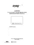
AOM-7694
7" FLAT PANEL COLOR OBSERVATION
MONITOR OWNER'S MANUAL
VOLUME
MENU
SELECT
DN
UP
AOM-7694 Feat ur es:
High-performance Automotive Grade 7" Color LCD Panel
4 Camera / A/V Inputs
A/V Selectable Navigation (RGB) or Camera (Composite)
Single / Split / Quad Display Modes
PAL/NTSC Compatible
1 Video Output for Display on External Video Monitor
DC Auto Source for Switching Triggers (Turn Signal Compatible)
Backlit Control Buttons
Built-in Audio Speaker
Compatible with Voyager Standard or Motorized Tilt Cameras
Manual/Auto Day/Night Display Brightness Modes
Programmable Source Name OSD
Flush-Mount Installation Kit Included
The Mobile Electronics Company
AUDIOVOX SPECIALIZED APPLICATIONS, L.L.C.
www.asaelectronics.com
Camera-Monitor Warnings!
1. Came ra/ mon itor system ai ds in the us e of , bu t do es no t rep lac e veh icle
side /rea r-view mi rror s.
2. Obj ec ts in came ra/ mon itor view ar e clos er tha n the y ap pe ar.
Whe n ba cking up , pr oc ee d cau tiou sly an d be pr ep ar ed to stop .
AOM-7694
IMPORTANT! - Please Read This Manual Before Installing!
Congratulations on your purchase of a Voyager AOM-7694 LCD Observation Monitor.
With proper installation and use, your AOM-7694 LCD is designed to provide you with years
of trouble-free operation. Please read this manual thoroughly prior to beginning.
All Voyager Observation products are strictly intended to be installed as a supplemental aid
to standard rear-view mirror systems that may already exist in your vehicle. Voyager
Observation products are not intended for use as substitutes for rear-view mirror devices or for
any other standard motor vehicle equipment required by law.
While Voyager observation products contribute to improving the vehicle operator's field
of view, these products are no substitute for proper defensive driving techniques and
observance of traffic laws and motor vehicle safety regulations.
Warnings!
RED POWER WIRE MUST BE CONNECTED TO ACCESSORY TO AVOID CURRENT
DRAW IN THE KEY OFF POSITION.
Installation Location
It is unlawful in most jurisdictions for a person to drive a motor vehicle equipped with a
television viewer or screen located at any point forward of the back of the driver's seat or
in any location that is visible, directly or indirectly, to the driver while operating
the vehicle. The AOM-7694 product is designed to be used primarily as a rear observation
device in conjunction with a closed circuit camera. In any installation where the AOM-7694
is used to display television broadcasts or recorded video, the installation location
must adhere to local laws and regulations.
Tampering
Moisture
Your Voyager AOM-7694 was not designed to be water-resistant. While it will withstand short
periods of exposure to moisture, this product does contain sensitive electronic
components and exposure to moisture should be limited by the user/installer. This product is
not designed for constant exposure to moisture or immersion.
This unit should NEVER be cleaned with a power washer or used where direct power washer
spray may be encountered.
Depth of view
OBJECTS VIEWED IN MONITOR ARE CLOSER THAN THEY APPEAR.
2
AOM-7694
PACKING CONTENTS
TRIM RING
QTY. 1
SUN SHIELD
QTY. 1
FLUSH MOUNT BRACKET
QTY. 1
LCD MONITOR
QTY. 1
CABLE QTY. 1
P/H Machine Screw
M4X10mm
QTY. 4
Flat Head Tapping Screw
M4X12mm
QTY. 4
4" BLACK WIRE TIE
QTY. 1
3
AOM-7694
CONTROLS AND OPERATION
VOLUME
MENU
1
SELECT
DN
UP
2 3 45 6 7 8
1. POWER ON/OFF
-Press once to turn the unit on.
-Press again to turn the unit off.
-With power applied and the unit turned off, only the red power button is backlit.
-When unit is turned on, all buttons are backlit.
2. MENU
-Press once to enter main menu mode (See Figure1).
-Press again before time out to exit the menu mode.
-Time out of OSD menu is approximately 8 seconds from when the last
key was pressed.
MENU
MAIN MENU
PRESS TO NAVIGATE UP/DOWN
BRIGHTNESS
CONTRAST
COLOR
TINT
INPUT SETUP
AUTO-SCAN
SPLIT SCREEN
DISTANCE MARKERS
ADVANCED MENU
PRESS TO EXIT MAIN MENU
PRESS TO GO BACK TO
MAIN MENU
Figure. 1 Main menu
PRESS TO ADJUST +/-
SELECT
'BRIGHTNESS'
BRIGHTNESS
PRESS TO GO BACK TO
MAIN MENU
4
AOM-7694
PRESS TO ADJUST +/-
SELECT
'CONTRAST'
CONTRAST
PRESS TO GO BACK TO
MAIN MENU
PRESS TO ADJUST +/-
SELECT
'COLOR'
COLOR
PRESS TO GO BACK TO
MAIN MENU
PRESS TO ADJUST +/-
SELECT
"TINT"
TINT
PRESS TO GO BACK TO
MAIN MENU
INPUT SETUP
SELECT
"INPUT SETUP"
PRESS TO ADJUST +/-
CH1: [ON(NORMAL) ; ON(MIRROR) ; OFF]
CH2: [ON(NORMAL) ; ON(MIRROR) ; OFF]
CH3: [ON(NORMAL) ; ON(MIRROR) ; OFF]
CH4: [ON(NORMAL) ; ON(MIRROR) ; OFF]
SOURCE NAME
PRESS TO GO BACK TO
MAIN MENU
SELECT
'SOURCE NAME'
PRESS TO NAVIGATE UP/DOWN
SOURCE NAME
CH1: _ _ _ _ _ _ _ _
CH2: _ _ _ _ _ _ _ _
CH3: _ _ _ _ _ _ _ _
CH4: _ _ _ _ _ _ _ _
PRESS TO SELECT CHANNEL TO
RENAME
PRESS TO MOVE TO NEXT LETTER
PRESS TO SCROLL THROUGH
ALPHA-NUMERIC CHARACTER SET
PRESS TO GO BACK TO
INPUT SETUP MENU
5
AOM-7694
AUTO SCAN
SELECT
"AUTO - SCAN"
PRESS TO NAVIGATE UP/DOWN
THROUGH MENU OPTIONS
SCAN: [OFF ; ON]
DELAY TIME: [1 sec. to 10 sec.]
PRESS TO TOGGLE THROUGH OR
SELECT MENU OPTION
PRESS TO GO BACK TO
MAIN MENU
PRESS TO NAVIGATE UP/DOWN
THROUGH MENU OPTIONS
SPLIT SCREEN
SELECT
"SPLIT
SCREEN"
2 - WAY
3 - WAY
4 - WAY
PRESS TO TOGGLE THROUGH OR
SELECT MENU OPTION
SELECT
"2-WAY"
PRESS TO GO BACK TO
MAIN MENU
PRESS TO NAVIGATE UP/DOWN
THROUGH MENU OPTIONS
2-WAY SPLIT
SOURCE 1: [CH1 ; CH2 ; CH3 ; CH4]
SOURCE 2: [CH2 ; CH3 ; CH4 ; CH1]
AUDIO: [CH? ; CH? ; OFF]
PRESS TO TOGGLE THROUGH OR
SELECT MENU SETTING
PRESS TO GO BACK TO
SPLIT SCREEN MENU
PRESS TO NAVIGATE UP/DOWN
THROUGH MENU OPTIONS
3-WAY SPLIT
SOURCE 1: [CH1 ; CH2 ; CH3 ; CH4]
SOURCE 2: [CH2 ; CH3 ; CH4 ; CH1]
SOURCE 3: [CH3 ; CH4 ; CH1 ; CH2]
AUDIO: [CH? ; CH? ; OFF]
PRESS TO TOGGLE THROUGH OR
SELECT OPTION SETTING
PRESS TO GO BACK TO
SPLIT SCREEN MENU
6
AOM-7694
PRESS TO NAVIGATE UP/DOWN
THROUGH MENU OPTIONS
4-WAY SPLIT
SOURCE 1: [CH1 ; CH2 ; CH3 ; CH4]
SOURCE 2: [CH2 ; CH3 ; CH4 ; CH1]
SOURCE 3: [CH3 ; CH4 ; CH1 ; CH2]
SOURCE 4: [CH4 ; CH1 ; CH2 ; CH3]
AUDIO: [CH1 ; CH2 ; CH4]
PRESS TO TOGGLE THROUGH OR
SELECT OPTION SETTING
PRESS TO GO BACK TO
SPLIT SCREEN MENU
PRESS TO TOGGLE THROUGH OR
SELECT MENU OPTION
DISTANCE MARKERS
SELECT
"DISTANCE
MARKERS"
MARKER OSD: [OFF ; CH1 TRIGGER]
PRESS TO GO BACK TO
MAIN MENU
PRESS TO NAVIGATE UP/DOWN
THROUGH MENU OPTIONS
ADVANCED MENU
SELECT
"ADVANCED
MENU"
TRIGGER PRIORITY : [CH1 ; CH2 ; CH3 ; CH4 ; SPLIT]
TRIGGER DELAY : [1 sec. to 10 sec]
PRESET
VIDEO FORMAT: [NTSC ; PAL]
OSD COLOR : [YELLOW ; WHITE ; MAGENTA]
PRESS TO TOGGLE THROUGH OR
SELECT OPTION SETTING
CH4 SOURCE : [AV ; NAVIGATION]
CH. SEL. ON TRIGGER : [ON ; OFF]
PRESS TO GO BACK TO
MAIN MENU
SELECT
'PRESET'
PRESS TO RECALL BRIGHTNESS,
CONTRAST, COLOR AND TINT
PRESET
PRESS TO GO BACK TO
MAIN MENU
7
AOM-7694
3. SELECT
Primary Function Input Source Select
SELECT
-Pressing the SELECT button to sequence the source input modes
as indicated in Figure 2.
-Source input modes that are skipped through the menu control
function will be skipped. (Figure 3 shows sequence with
CAM/INPUT 3 skipped.)
-Source ID is indicated by OSD in the top left corner of the screen.
-Source NAME is indicated by OSD in the bottom center of the screen.
Secondary Function Menu Option Selection
-While in Menu mode, the SELECT button is used to select the
highlighted function or option setting.
Third Function Scan Pause / Start
-While in source "SCAN" mode, pressing the select button will stop
the scan and display the current source. "Pause" will be displayed
by OSD.
Press SELECT again to resume source scan.
CH1
CH2
SPLIT(4-WAY)
CH3
SPLIT(3-WAY)
CH4
SPLIT(2-WAY)
Figure 2: Source Select Sequence
(All Source Options "On" )
CH1
CH2
SPLIT(4-WAY)
SPLIT(3-WAY)
CH4
SPLIT(2-WAY)
Figure 3: Source Select Sequence
(CH3 "Skip" )
8
AOM-7694
4. UP / DOWN
Primary Function Camera Control
DN
UP
-Press the DN button to adjust the camera position downward.
-Press the UP button to adjusts the camera position upward.
Secondary Function Menu Navigation
-While in Menu modes, the UP and DN buttons are used to
navigate through available menu options.
5. Day / Night
Primary Function DAY/NIGHT Mode Setting
-Press the DAY/NIGHT button to sequence day/night backlight
compensation through "DAY", "NIGHT" and "AUTO" modes.
-Current mode setting is indicated by a temporary OSD located
at the bottom center of the screen.
6. Volume +/Primary Function Speaker Volume Control
-Press the + button to increase the speaker volume.
-Press the - button to decrease the speaker volume.
Secondary Function Menu Option Setting Selection
-While in certain Menu modes ( Picture Adjustment, Source
Naming), the + and - buttons adjust settings or navigate through
available menu settings.
9
AOM-7694
Installation Instructions
BEFORE YOU BEGIN INSTALLATION:
Before drilling, be sure that no cable or wiring is on the other side. Clamp all wires securely
to reduce the possibility of them being damaged during installation and use.
Keep all cables away from hot or moving parts and electrically noisy components.
Wiring Definitions:
Power Connection:
Pin 1
Pin 2
Pin 3
Pin 4
Pin 5
Pin 6
Pin 7
Pin 8
CHANNEL 1 TRIGGER -Blue
CHANNEL 2 TRIGGER - Brown
CHANNEL 3 TRIGGER -Green
POWER IN DC (10 TO 32V) -Red
AUDIO/MUTE (AUDIO ON/OFF) -White
CHANNEL 4 TRIGGER -Orange
GROUND -Black
2-WAY SPLIT TRIGGER -Yellow
Camera 1 Input:
5-Pin
Connection for tilt camera or camera
extension cable
Camera 2 Input:
4-Pin
Connection for camera or camera extension cable
Camera 3 Input:
4-Pin
Connection for camera or camera extension cable
Camera 4 Input:
4-Pin
Connection for camera or camera extension cable
LCD Panel:
25-Pin D-Sub Cable connection to monitor
General:
1. Choose the monitor and camera locations.
2. Install all required cables in vehicle. A 3/4" (19mm) hole should be drilled for
passing camera cables through vehicle walls, barriers, etc.
I nstall split grommets where applicable. If additional cable protection is
required, install convoluted tubing over the cable.
3. After cable/wiring has been routed and components are in place, temporarily make all
system connections and perform a system function check. If the system does not
operate properly, see the troubleshooting section.
4. Make sure all cables are routed away from hot or moving parts and away from
sharp edges. Secure cables with wire ties.
10
AOM-7694
Backup (Rear) Camera
Rear-mounted cameras used for monitoring while backing up must be
connected to the CA1 input. Trigger#1 must be connected to the reverse gear light
circuit in the vehicle.
There are two camera options for rear camera installations: standard and tilt.
Tilt cameras and cables will connect directly to the 5-pin CA1 input. If a
standard(non-tilt) camera is installed as the rear camera, a 5-pin to 4-pin adapter
harness (included) must be used.
Side Camera
If side monitoring cameras are installed, they should be connected to either CA2 or
CA3 inputs. Triggers 2 and 3 should be connected to the vehicle's turn signal circuits.
Navigation
If a navigation computer is installed using the Component input, select the
Navigation setting from the Advanced menu for Source 4. Connect the Red, Green,
Blue and Brown RCA connectors from the AOM-7694 to the Navigation unit. Adapter
harness (1126810) is requir e d to convert from the 4-pin camera connector to RCA
connectors and must be connected to Camera 4 input. Ues the R e d RCA connector
from the harness to connect to the Navigation unit's audio output.
If a navigation computer is installed using the Composite input, select the A/V
setting from the Advanced menu for Source 4. Adapter harness (1126810) is required
to convert from the 4-pin camera connector to RCA connectors. Use the Yellow RCA
connector to the Navigation unit's composite Video output and the Red RCA
connector to connect to the Navigation unit's audio output.
Note: If connecting a Camera to the Camera 4 input, the Advanced Menu setting for
Source A/V 4 must be set to A/V.
A remote control repeater connection (1/8 jack) is included to allow control of the
navigation computer through the sensor on the front of the AOM-7694 monitor.
External (Additional) Monitors
An RCA video output is included and intended for connection to an external monitor
(i.e.bedroom TV).
Channel Selection On Trigger
The normal (default) operation is "OFF". To turn this feature on go to the Advanced
Menu and select "ON". When "OFF", the Camera selection button will not function
when a trigger wire is active. When "ON", the user can manually override
the triggered camera by using the Camera selection button.
11
AOM-7694
Typical System
Connection
AO M-7694
MO NI T O R
A
MALE
CHANNEL 1
5-PI N FEMAL E CO NNECT O R
( S-VI DEO T YPE)
RED GRN BLU BRO
FEMALE
DET AI L -A
CAMERA4
RED
:
G REEN :
BL UE
:
BRO W N :
CHANNEL 2~4
4-PI N ASA FEMAL E
CAMERA CO NNECT O R
( 3-VI DEO T YPE)
R Si g n al I n p u t
G Si g n al I n p u t
B Si g n al I n p u t
H, V Syn c Si g n al
MO L D-O VER
ST RAI N REL I EF
- OPTION For standard
ASA 4 pin
camera
in CHANNEL 1
YEL L O W F EMAL E
RCA CO NNECT O R
( VI DEO O UT )
VIDEO OUT
1/8" S T EREO JACK
( 3-W I RE)
(IR COMMAND REPEAT)
T O NAVI G AT I O N
5
1 2 34 67 8
BLUE
31100014 CABL E
12
CHANNEL 1 TRIGGER
BROWN
CHANNEL 2 TRIGGER
GREEN
CHANNEL 3 TRIGGER
RED
POWER IN DC (10 TO 32V)
WHITE
AUDIO/MUTE (AUDIO ON/OFF)
ORANGE
CHANNEL 4 TRIGGER
BLACK
GROUND
YELLOW
2-WAY SPLIT TRIGGER
AOM-7694
PRODUCT SPECIFICATIONS
LCD PANEL SPECIFICATIONS
Size/Type
7" (DIAGONAL) TFT LCD
Brightness
500 cd/㎡ (typ)
Contrast Ratio
300 (typ)
View Angles
Top (12 o'clock)
40° (mi n)
Bottom (6 o'clock)
60° (mi n)
Horizontal
±60° (mi n)
(@ CR≥10)
Rise : 12 ms (typ)
Response Time
Fall : 18 ms (typ)
Backlight Type
CCFL
Backlight Life
10,000 hrs (mi n)
Operation Temperature Range : -20℃ ~ +65℃
Storage Temperature Range : -40℃ ~ +80℃
Max Humidity : 85%
Operation Voltage Range : DC 10V ~ 32V
Current Draw (typical) : Max 30W
Signal system : NTSC or PAL (selectable)
Video Aspect Ratio : 16 : 9
Input Level : 1Vp-p 75Ω
Ω
Audio Input Level : Max 0.2 W-150 ㎷
Product Weight : 2.2 Ibs / 1Kg
Product Dimensions : Monitor Only Dimensions:
7.75 W X 5.25 H X 1.25D inches
Flange Dimensions
9.25 W X 6.25 H X 2 D inches
13
AUDIOVOX SPECIALIZED APPLICATIONS, L.L.C.
www.asaelectronics.com
Printed in Korea