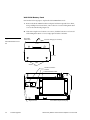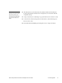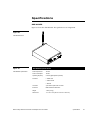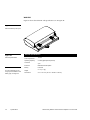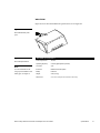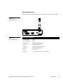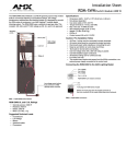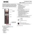
1
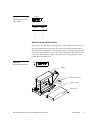
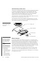
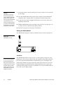
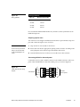
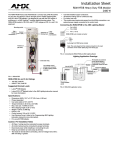
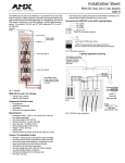
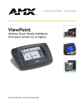
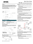
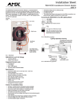
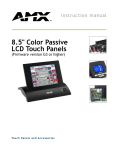
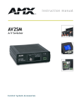
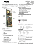
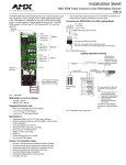
WAVE 2-Way Wireless Accessories and Adapters for Touch Panels Instruction Manual Control Panel Accessories Limited Warranty and Disclaimer Panja Inc. warrants its products to be free from defects in material and workmanship under normal use for a period of three years from date of purchase from Panja, Incorporated, with the following exceptions. Electroluminescent and LCD control panels are warranted for a period of three years, except for the display and touch overlay components which are warranted for a period of one year. Disk drive mechanisms, pan/tilt heads, power supplies, modifications, MX Series products, and KC Series products are warranted for a period of one year. Unless otherwise specified, OEM and custom products are covered for a period of one year. Panja Inc. software products are warranted for a period of 90 days. Batteries and incandescent lamps are not covered. This warranty extends to products purchased directly from Panja Inc. or an authorized Panja Inc. dealer. Consumers should inquire from selling dealer as to the nature and extent of the dealer’s warranty, if any. Panja Inc. is not liable for any damages caused by its products or for the failure of its products to perform, including any lost profits, lost savings, incidental damages, or consequential damages. Panja Inc. is not liable for any claim made by a third party or made by you for a third party. This limitation of liability applies whether damages are sought, or a claim is made, under this warranty or as a tort claim (including negligence and strict product liability), a contract claim, or any other claim. This limitation of liability cannot be waived or amended by any person. This limitation of liability will be effective even if Panja Inc. or an authorized representative of Panja Inc. has been advised of the possibility of any such damages. This limitation of liability, however, will not apply to claims for personal injury. Some states do not allow a limitation of how long an implied warranty lasts. Some states do not allow the limitation or exclusion of incidental or consequential damages for consumer products. In such states, the limitation or exclusion of the Limited Warranty may not apply to you. This Limited Warranty gives you specific legal rights. You may also have other rights that may vary from state to state. You are advised to consult applicable state laws for full determination of your rights. EXCEPT AS EXPRESSLY SET FORTH IN THIS WARRANTY, PANJA INC. MAKES NO OTHER WARRANTIES, EXPRESS OR IMPLIED, INCLUDING ANY IMPLIED WARRANTIES OF MERCHANTABILITY OR FITNESS FOR A PARTICULAR PURPOSE. PANJA INC. EXPRESSLY DISCLAIMS ALL WARRANTIES NOT STATED IN THIS LIMITED WARRANTY. ANY IMPLIED WARRANTIES THAT MAY BE IMPOSED BY LAW ARE LIMITED TO THE TERMS OF THIS LIMITED WARRANTY. Table of Contents Introduction ............................................................................ 1 Overview 1 Features 2 What’s in this Manual 2 What’s New 3 AXR-WAVES 3 WAV-PK 3 WAV-PKM 3 WAV-LNK WaveLink 4 WAV-PM WaveLink power module 4 Related Instruction Manuals 4 Sample Product Application 5 AXR-WAVES 5 Front panel 5 Rear panel 7 WAV-PK 7 Front panel 7 Rear panel 8 WAV-PKM 8 Front panel 8 Rear panel 9 WAV-LNK WaveLink 9 Front panel 10 Rear panel 10 Optional WAV-PM WaveLink Power Module 11 Front panel 11 Rear panel 12 Power management 13 Batteries Safe handling and usage of the battery 13 14 Standard Power Supply 14 Optional WAV-CHG Fast-Cycle Battery Charger 15 Pre-Installation ..................................................................... 17 Overview 17 AXR-WAVES (or WAV-LNK) Group Address DIP Switch WAVE 2-Way Wireless Accessories and Adapters for Touch Panels 17 Table of Contents i AXR-WAVES (or WAV-LNK) Group ID DIP Switch 18 WAV-PK Group ID DIP switch 19 WAV-PKM Group ID DIP switch 20 Battery Charging 20 WAV-PM WaveLink Power Module 21 Installation ............................................................................ 23 Overview 23 Installing the Control System 23 Wiring the AXR-WAVES 24 Guidelines 24 Preparing captive wires 25 Connecting AXlink for data and power 25 Installing the WAV-PK 26 WAV-PK Battery Replacement Installing the WAV-PKM WAV-PKM Battery Replacement Installing the WAV-PM 27 28 29 31 Single WAV-PM module 31 Multiple WAV-PM modules 32 Firmware Upgrades.............................................................. 33 Overview 33 AXR-WAVES Server Firmware 33 WAV-PK Battery Pack Firmware 34 WAV-PKM Battery Pack 36 Specifications....................................................................... 39 AXR-WAVES 39 WAV-PK 40 WAV-PKM 41 WAV-BP and WAV-BPM Batteries 42 WAV-LNK WaveLink 43 WAV-PM Power Module 44 Contacting Sales and Technical Support ........................... 45 ii Table of Contents Overview 45 U.S. Sales and Technical Support Teams 45 Panja International Offices 46 Technical Support 46 WAVE 2-Way Wireless Accessories and Adapters for Touch Panels Introduction Overview The AXR-WAVES Wireless AXlink Virtual Emulator Server (Figure 1) is a 2-way Radio Frequency (RF) device employing spread spectrum communications. A single AXR-WAVES can communicate with up to 16 wireless TiltScreen touch panels equipped with WAV-PK or WAV-PKM Wireless Power Packs. The WAV-PK and WAV-PKM are designed to enable 2-way wireless mobility of full-sized and minitouch panels, thus eliminating the need for permanent installation of a touch panel. Refer to the ViewPoint Touch Panel Cleaning, Charging, and Battery Replacement quick reference guide for more information on other products that use battery packs. Figure 1 AXR-WAVES WAVE Server, AXR-WAVES WAV-PK, and WAV-PKM. WAV-PKM WAV-PK WAVE 2-Way Wireless Accessories and Adapters for Touch Panels Introduction 1 Additionally, the WAV-LNK WaveLink transceiver (Figure 2) may be used in conjunction with one or more WAV-PM modules when a UniMount or rack mounted touch panel is used in a remote, wireless application. The WAV-LNK is ideal for UniMount touch panels mounted in podiums or lecterns where cabling is of concern. Figure 2 WAV-LNK transceiver Features The major features for the AXR-WAVES, WAV-LNK, WAV-PK, and WAV-PKM are described in the following paragraphs. Additionally, information for the WAV-PM power module is provided. What’s in this Manual This manual comprises the following sections: Pre-Installation Settings Describes how to set the GROUP ADDRESS and GROUP ID DIP switches. Installation Describes how to install and wire the AXR-WAVES, WAV-PK, WAV-PKM, WAV-PM, WAV-BP, and WAV-BPM. Firmware Upgrade Provides the disassembly and installation requirements for upgrading the AXR-WAVES, WAV-PK, and WAV-PKM firmware integrated circuits (ICs). Specifications Briefly describes the AXR-WAVES, WAV-PK, WAV-PKM, WAV-PM, WAV-BP, and WAV-BPM specifications for each unit. Technical Support Lists the telephone numbers to contact Sales and Techni- cal Support. 2 Introduction WAVE 2-Way Wireless Accessories and Adapters for Touch Panels What’s New Updates to this manual include: • Battery usage, safety warnings, and caution information • Updated technical support information All other revisions are identified by vertical margin bars as shown adjacent to this paragraph. AXR-WAVES AXR-WAVES features include: • 2-way RF communications with up to 16 TiltScreen touch panels equipped with wireless power packs • 2-way communication via a 2.4 GHz frequency hopping, spread spectrum technology WAV-PK Note The WAV-PK contains two small lithium batteries that will last approximately 5 years. The batteries are not user replaceable, and the WAV-PK must be returned to Panja for battery replacement. Note The most recharge cycles are available when the battery is recharged before the battery WAV-PK features include: • 2-way RF communications with an AXR-WAVES server • Mobility for full-sized TiltScreen touch panels • Integrated power management features for longer battery life • Built-in antenna • Rechargeable lead-acid battery (WAV-BP WavePack Battery) • Lithium battery maintains the flash RAM WAV-PKM WAV-PKM features include: drains completely. • 2-way RF communications with an AXR-WAVES server • Mobility for Mini-TiltScreen Touch Panels • Integrated power management • Built-in antenna WAVE 2-Way Wireless Accessories and Adapters for Touch Panels Introduction 3 Note The WAV-PKM contains two • Rechargeable lead-acid battery (WAV-PKM Mini-WavePack Battery) • Lithium battery maintains the flash RAM small lithium batteries that will last approximately 5 years. The batteries are not user replaceable and the WAV-PKM must be returned to Panja for battery replacement. WAV-LNK WaveLink The WAV-LNK WaveLink transceiver features include: • 2-way RF spread-spectrum communications with an AXR-WAVES server. • Operates from an external power supply and/or one or more WAV-PM power modules. • Integrated battery charge circuitry. • Unit is rack-mountable using an optional AC-RK Accessory Rack Kit. • Interface capabilities for up to 16 AXlink devices. WAV-PM WaveLink power module The WAV-PM WaveLink Power Module features include the following: • Provides up to 3 amps of current • Uses 2.3 AH, 12 VDC lead-acid battery (same as used in the WAV-PK) • Built-in, fast-cycle charging circuitry • Easy battery replacement • Front panel battery charge level gauge • Overload protection and indication • Battery charging indicator • Can be daisy-chained with other WAV-PM modules to provide a maximum 12 VDC @ 10 AMP for extended WAV-LNK operating time • Rack mountable using the optional AC-RK Accessory Rack Kit Related Instruction Manuals These instruction manuals contain additional information that relates to the Wave 2Way Wireless Accessories and Adapters for Touch Panels. 4 Introduction • Black/White Mini-Touch Panels (Firmware version G3 or higher) • Black/White Touch Panels (Firmware version G3 or higher) • ViewPoint Touch Panel Cleaning, Charging, and Battery Replacement WAVE 2-Way Wireless Accessories and Adapters for Touch Panels Sample Product Application The AXR-WAVES connects to a Central Controller and communicates with a wide variety of touch panels. The WAV-PK and WAV-PKM power packs connect to fullsized and mini-touch panels to provide mobility and communications with an AXRWAVES. Figure 3 shows a sample control system using an AXR-WAVES communications configuration. AXT-CP AXT-CA Figure 3 AXT-MCA Sample Central Controller and AXR-WAVES communica- (connects to rear panel) tions application Power supply WAV-PK WAV-PKM AXCESS CentralCardFrame Controller PIN 1 -1- PWR(+) AXP AXM GND(-) PWR(+) AXP AXli AXM SLOT SLOT SLOT GND(-) PIN PWR(+) AXP AXM GND(-) M1 RS- - + 1P2WVRD C NOM AXR-WAVES (rear panel) AXR-WAVES The AXR-WAVES front and rear panel controls and indicators are described in the following paragraphs. Front panel The AXR-WAVES front panel provides an AXlink LED status indicator, GROUP ADDRESS DIP switch, GROUP ID DIP switch, STATUS LED, and RX LED indicator as shown in Figure 4. WAVE 2-Way Wireless Accessories and Adapters for Touch Panels Introduction 5 Figure 4 AXR-WAVES front panel • AXlink—Green LED that blinks when there is AXlink communication activity. The green AXlink LED indicates the following power and data activity: One blink per second: Power is active and AXlink data communication is functional. —Full on: Power is active and AXlink data communication is not functional. • GROUP ADDRESS—Eight-position DIP switch sets the group address (0 through 255). • GROUP ID—Four-position DIP switch sets the control group identification address (0 through 15). 6 Introduction • STATUS—Red • RX—Red LED flashes periodically during normal operation. LED lights when the AXR-WAVES receives RF control data. WAVE 2-Way Wireless Accessories and Adapters for Touch Panels Rear panel The rear panel has an RF antenna and a 4-pin AXlink bus connector. Figure 5 shows the AXR-WAVES rear panel. Figure 5 AXR-WAVES rear panel • ANTENNA—Right-angle, • AXlink—Four-pin (male) connector connects to the Central Controller to receive AXlink control data and 12 VDC power. flexible, bi-directional RF antenna. WAV-PK The WAV-PK full-sized TiltScreen touch panel controls and indicators are described in the following paragraphs. Front panel The front of the WAV-PK power pack contains a connector that mates with the fullsized TiltScreen touch panels. This connector provides both power and data connections. Figure 6 shows the WAV-PK front panel and connector. WAVE 2-Way Wireless Accessories and Adapters for Touch Panels Introduction 7 Figure 6 WAV-PK power pack front panel and connector Rear panel The WAV-PK rear panel provides a barrel power (plug-in) connector for operating or recharging of the unit. There is also a wake-up switch located in the center-rear of the WAV-PK. Figure 7 shows the rear of the unit and the power connector. Figure 7 WAV-BP battery Battery clip WAV-PK rear panel Group ID switch ON 1 2 3 4 Wake-up switch Power supply connector WAV-PKM The WAV-PKM Mini-TiltScreen touch panel controls and indicators are described in the following paragraphs. Front panel The WAVE-PKM power pack connects to the Mini-TiltScreen touch panel. Figure 8 shows a front view of the WAV-PKM and connector cable. 8 Introduction WAVE 2-Way Wireless Accessories and Adapters for Touch Panels Figure 8 WAV-PKM front panel Rear panel The WAV-PKM rear panel provides a power connector for operating or recharging of the unit. Figure 9 shows the rear of the unit and the power connector. Figure 9 Power supply connection WAV-PKM rear panel WAV-LNK WaveLink The WAV-LNK WaveLink transceiver provides an interface for up to 16 touch panels or similar AXlink type devices. The WAV-LNK communicates with the AXRWAVES and allows connecting devices requiring AXlink communications. The following paragraphs describe the controls and indicators on the WAV-LNK front and rear panels. WAVE 2-Way Wireless Accessories and Adapters for Touch Panels Introduction 9 Front panel Figure 10 shows the front panel for the WAV-LNK and its switches and indicators are described below. Figure 10 WAV-LNK front panel • AXlink—This • GROUP ADDRESS—Eight-position LED lights when an active AXlink connection is established. DIP switch sets the group address (0 through 255). • GROUP ID—Four-position DIP switch sets the control group identification address (0 through 15). • STATUS—Red • RX—Red LED lights when the WAV-LNK LED flashes during normal operation. receives RF control data. Rear panel Figure 11 shows the WAV-LNK rear panel and its connectors. They are: 10 Introduction • AXlink—The AXlink connector provides a 4-wire connection to any device (including a CardFrame equipped with an AXC-EM Enhanced Master controller) which uses AXlink signaling. This connection also provides power out to the connected devices. • PWR—The PWR connector is used when connecting an external power supply, such as one or more WAV-PK power modules or a PS4.2 power supply. WAVE 2-Way Wireless Accessories and Adapters for Touch Panels Figure 11 WAV-LNK rear panel 12VDC − + PWR Optional WAV-PM WaveLink Power Module Note The WAV-PM WaveLink Power Module will only accept only the full-sized WAV-BP The WAV-PM WaveLink Power Module provides additional wireless backup power to a WaveLink device. WAV-PMs can be daisy-chained to provide 12 VDC at up to 10 A. The following paragraphs identify and define controls and indicators for the optional WAV-PM WaveLink Power Module. batteries. Front panel Figure 12 shows the WAV-PM front panel, and the following paragraphs define the controls and indicators. Figure 12 WAV-PM front panel Overload indicator Release lever Charging indicator Test push-button Empty/full gauge WAVE 2-Way Wireless Accessories and Adapters for Touch Panels Introduction 11 Note • BATTERY indicator gauge (empty-full) provides a visual indication of the charge level of the battery currently being used. If the battery's charge is high, all left-to-right indicator lamps will be lit. • Test—Pressing the TEST button displays an indication of the current battery's charge level on the front panel’s Empty/Full gauge. • Charging—The CHARGING indicator lights when the module is currently charging a battery. The indicator goes off when the battery is fully charged. • Overload—The OVERLOAD indicator lights when the WAV-PM WaveLink Power Module is used in an application that requires more current/voltage than can be supplied by the module. • Battery Release—The While a battery is charging, the Empty/Full gauge—The Empty/Full indicator does not show a valid reading. Caution Ensure that the WAV-PM application environment does not require a greater supply current than the module can provide. If the system is over- battery release lever, when pushed to the right, releases the battery from the module clasps and enables removal. loaded, irreparable damage could occur to the module. Rear panel Figure 13 shows the WAV-PM WaveLink Power Module rear panel. Controls and indicators are defined as follows. Figure 13 WAV-PM rear view 12 Introduction • OUT—This is a 2-wire connector which provides a 12 VDC, 3 AMP output which can be connected to a WAV-LNK Control System or to another WAVPM module. • IN—A 2-wire connector for accepting 12 VDC input power from another WAV-PM module. • PWR—When using power input from a separate 12 VDC power supply, connect to this 2-wire connector. WAVE 2-Way Wireless Accessories and Adapters for Touch Panels Power management The Wave Packs incorporate advanced power management schemes that reduce overall power consumption. Power management is software-controlled by the individual touch panel program. The user tells the WavePack when to go into power conservation mode (sleep mode). Pressing the rear-mounted WAV-PK wake-up switch activates the WavePack. The WAV-PK physically provides a wake-up switch on its rear panel. The WAVPKM wakes up when someone touches the touch panel screen. Refer to the instruction manual supplied with your touch panel for detailed information. Batteries The batteries (Figure 14) used for the WAV-PK and WAV-PKM are rechargeable lead-acid batteries. There are two different sizes used, WAV-BP for the full-sized TiltScreen touch panels and WAV-BPM for the Mini-TiltScreen touch panels. Figure 14 WAV-BP battery WAV-PK and WAV-PKM batteries Caution Keep the following important safety considerations in mind when using the WAV-BP and WAV-BPM batteries: • Do not incinerate. • Do not directly connect the WAV-BPM battery negative and positive terminals. • Do not use with battery chargers other than the The recharge life of the lead-acid batteries is dependent on the discharge depth of the battery at the time of re-charge. See Figure 15 for charge cycle availability. WAV-PK and WAV-PKM. Figure 15 Charge cycle availability Charge cycle availability Discharge depth Charge cycles available 100% 200 50% 450 30% 1200 WAVE 2-Way Wireless Accessories and Adapters for Touch Panels Introduction 13 Safe handling and usage of the battery To prevent deterioration or damage to the battery: • Do not use battery to power equipment other than the WAV-PK or WAVPKM. • Do not drop or subject the battery to strong physical shock. • Do not use the battery below -10°C (15°F) or above +40°C (105°F). If the temperature exceeds this upper limit, a safety device automatically prevents operation of the battery. Standard Power Supply Note The WAV-BP or WAV-BPM battery must be charged before use. Either battery will require a 4-hour charge. The standard power supply furnished with the WAV-PK and WAV-PKM is shown in Figure 16. The power supply can be used for primary power or battery charging of the WAV-PKs or WAV-PKMs battery. Refer to the Battery Charging subsection in this manual for more information. The power supply barrel connector plugs into the side of the WAV-PK or the back of the WAV-PKM. Figure 16 Power supply/battery charger 14 Introduction WAVE 2-Way Wireless Accessories and Adapters for Touch Panels Optional WAV-CHG Fast-Cycle Battery Charger The WAV-CHG Fast-Cycle Battery Charger is shown in Figure 17. The charger will charge two batteries simultaneously. Refer to the Battery Charging subsection of this manual. The charger provides a fast-cycle, 4-hour, full-charge capability. Figure 17 LED charging indicator Optional battery charging holder and power supply CHARGE POWER CHARGE Power Supply Power supply connector Battery holder with Fast-Cycle circuitry WAVE 2-Way Wireless Accessories and Adapters for Touch Panels Introduction 15 16 Introduction WAVE 2-Way Wireless Accessories and Adapters for Touch Panels Pre-Installation Overview Before installing the wireless communications equipment, set the AXR-WAVES GROUP ADDRESS DIP switch. Then, set the GROUP ID DIP switches for the AXRWAVES, WAV-LNK, WAV-PK, and WAV-PKM. Figure 18 shows the DIP switches on the AXR-WAVES front panel. Figure 18 AXR-WAVES front panel AXR-WAVES (or WAV-LNK) Group Address DIP Switch Note Device numbers must fall within the device number range set on the AXRWAVES. Note Settings of both DIP switches on the AXR-WAVES must match both DIP switch settings on the WAV-LNK for proper operation. A single AXR-WAVES server can communicate with up to 16 wireless devices. The 8-position GROUP ADDRESS DIP switch sets the starting address (+ 15) for the group device numbers. For example, if the DIP switch is set to 128, the AXR-WAVES (or WAV-LNK) allocates device numbers 128 through 143 (128+15). The Group Address DIP switch setting on the WAV-LNK must be set identical to the Group Address switch setting on the AXR-WAVES server. Device numbers for the WAV-PK and the WAV-PKM commonly begin at 128 and are set using touch-screen menus on the full-sized and mini-touch panels. Refer to the instruction manual supplied with your touch panel for detailed information. WAVE 2-Way Wireless Accessories and Adapters for Touch Panels Pre-Installation 17 Figure 19 shows the AXR-WAVES GROUP ADDRESS DIP (or WAV-LNK) switch and a quick reference for the DIP switch numbers and their values. GROUP Figure 19 GROUP ADDRESS and DIP 1 2 3 4 5 6 7 8 ON ADDRESS switch settings quick reference DIP switch settings Switch Value 1 1 2 2 3 4 4 8 5 16 6 32 7 64 8 128 AXR-WAVES (or WAV-LNK) Group ID DIP Switch Note The GROUP ID DIP switch setting must be identical on the server and the WavePack. The four-position GROUP ID DIP switch sets the identification number to synchronize communication between the wireless devices and AXR-WAVES. Each AXRWAVES must have a unique GROUP ID number. The maximum number of AXRWAVES you can connect to a Central Controller is 16. When a WAV-PK or WAVPKM falls within the device number range set on the AXR-WAVES GROUP ADDRESS DIP switch, it must also be set to the same GROUP ID number. The Group Address DIP switch setting on the WAV-LNK must be set identical to the Group Address setting on the AXR-WAVES server. For example, if the AXR-WAVES (or WAV-LNK) GROUP ADDRESS DIP switch is set to 128 and the GROUP ID DIP switch is set to 1, the WAV-PK, WAV-PKM, or WAV-LNK devices 128 through 143 must have their GROUP ID DIP switch set to 1. If the AXR-WAVES GROUP ID number does not match the WAV-PK, WAV-PKMs, or WAV-LNK GROUP ID, they will not communicate properly. Figure 20 shows a GROUP ID DIP switch and a quick reference for the DIP switch numbers and their values. 18 Pre-Installation WAVE 2-Way Wireless Accessories and Adapters for Touch Panels GROUP Figure 20 GROUP ID DIP switch and 1 2 switch settings 3 4 ON ID DIP switch settings Switch Value 1 1 2 2 3 4 4 8 WAV-PK Group ID DIP switch The 4-position group ID DIP switch (Figure 21) sets the identification number to synchronize communication between the wireless WAV-PK and the AXR-WAVES (or WAV-LNK). Each AXR-WAVES (or WAV-LNK) must have a unique group ID number and each WAV-PK must have its 4-position group ID DIP switch set to the same value as the AXR-WAVES group ID value. The 4-position group ID DIP switch is located under the battery cover. Figure 21 WAV-PK group ID DIP switch ON 1 2 3 4 Battery Group ID DIP switch ON 1 2 3 4 Wake-up switch ON 1 2 3 4 Battery cover WAVE 2-Way Wireless Accessories and Adapters for Touch Panels Pre-Installation 19 WAV-PKM Group ID DIP switch The 4-position Group ID DIP switch (Figure 22) sets the group identification number to synchronize communication between the wireless WAV-PKM and the AXRWAVES (or WAV-LNK). Each AXR-WAVES (or WAV-LNK) must have a unique group ID number and each WAV-PKM must have its 4-position group ID DIP switch set to the same value as the AXR-WAVES group ID value. If the AXR-WAVES (or WAV-LNK) and WAV-PKM group ID switches are not set to the same values, valid communications will not occur. The group ID DIP switch for the WAV-PKM is located under the top cover of the unit. (To gain access to the DIP switch, refer to Installing the WAV-PKM subsection of this manual for gaining access to the DIP switch.) Figure 22 WAV-PKM GROUP ID DIP ON 1 2 3 4 Battery cover switch location Battery compartment To mini-touch panel Group ID DIP switch Note The WAV-BP or WAV-BPM battery must be charged before use. Either battery will require a minimum 4-hour charge. Caution Keep the following important safety considerations in mind when using the WAV-BP and WAV-BPM batteries: • Do not incinerate. • Do not directly connect the negative and positive ter- Battery Charging Charging the WAV-BP or WAV-BPM WavePack battery is accomplished with the battery still inside the WAV-PK (or the WAV-PKM), or by removing the battery and recharging it in the optional WAV-PM WaveLink Power Module (for WAV-BP batteries only), WAV-CHG Fast-Cycle Battery Charger, or the WAV-PM WaveLink Power Module. The WAV-PK and WAV-PKM have built-in charging circuitry and can recharge a battery in approximately 4 hours. Optionally, two batteries can quickcharge in a WAV-CHG Fast-Cycle Battery Charger is used (Figure 23). The optional WAV-CHG Fast-Cycle Battery Charger charges two batteries at the same time, or one at a time. With multiple batteries, you can use one battery and charge up to two more. The WAV-CHG produces a full charge for one or two batteries in approximately 4 hours. minals. • Do not use with battery chargers other than the WAV-PK and WAV-PKM. 20 Pre-Installation WAVE 2-Way Wireless Accessories and Adapters for Touch Panels Fully charged WAV-BP and WAV-BPM lead-acid batteries provide approximately 2hours of continuous touch panel operation running at full LCD brightness. However, you can use the touch panel's sleep mode and LCD timeout features to significantly increase the operation time per charge. Refer to the touch panel's instruction manual to activate these features. Figure 23 LED charging indicator Optional WAV-CHG FastCycle Battery Charger CHAR POW CHAR Power Supply DC Power supply connector Battery holder with Fast-Cycle circuitry WAV-PM WaveLink Power Module In addition to being a power source, the WAV-PM WaveLink Power Module has built-in fast charging circuitry that will allow charging of a 12 VDC, 2.3 AH battery in approximately four hours. WAVE 2-Way Wireless Accessories and Adapters for Touch Panels Pre-Installation 21 22 Pre-Installation WAVE 2-Way Wireless Accessories and Adapters for Touch Panels Installation Overview The AXR-WAVES can be installed on any flat surface. The following describes how to set up and install an AXR-WAVES communications system. Installing the Control System Install the control system, AXR-WAVES, WAV-PK, and WAV-PKM as follows. Figure 24 shows a sample Central Controller configuration. AXT-CA AXT-CP Figure 24 AXT-MCA Sample control system (connects to rear panel) Power supply WAV-PK WAV-PKM AXCESS CardFrame Central Controller PIN 1 -1- PWR(+) AXP AXM GND(-) PWR(+) AXP AXli AXM SLOT SLOT SLOT GND(-) PIN PWR(+) AXP AXM GND(-) M1 RS- - + 1P2WVRD C NOM WAVE 2-Way Wireless Accessories and Adapters for Touch Panels AXR-WAVES (rear panel) Installation 23 1. Mount the Central Controller in the position where it will be used. Connect the Caution AXR-WAVES uses spreadspectrum signaling to avoid common problems associated with RF control. However, it's wise not to place AXR-WAVES components next to microwave ovens, spread-spectrum or consumer micro-wave video link transceivers, or projectors using Halide or Xenon lamps. power supply. 2. Place the AXR-WAVES in the position where it will be used. The RF antenna should be set in a vertical position to communicate with the touch panels. 3. Position the touch panels, equipped with Wireless Power Packs, in the areas where they will be used. 4. Multiple AXR-WAVES can be used in the same local servers/groups (up to 16) as long as each has a different group address number. 5. Each server/group can contain up to 16 TiltScreens. Wiring the AXR-WAVES The AXR-WAVES rear panel contains an AXlink connector as shown in Figure 25. Figure 25 AXR-WAVES connector Guidelines Caution Do not connect the AXlink cable to the AXR-WAVES yet. Disconnect the wiring from the CardFrame before con-necting the AXlink cable to the AXRWAVES. Apply power to the The AXR-WAVES requires 12 VDC power to operate properly. The power is supplied by the control system’s AXlink cable. The maximum wiring distance between the control system and AXR-WAVES is determined by power consumption, supplied voltage, and the wire gauge used for the cable. Figure 26 lists wire sizes and maximum lengths allowable between the AXR-WAVES and control system. The maximum wiring lengths are based on a minimum of 13.5 volts available at the control system’s power supply output. AXR-WAVES only when the installation is complete. 24 Installation WAVE 2-Way Wireless Accessories and Adapters for Touch Panels Figure 26 Wiring guidelines Wiring guidelines Wire size Maximum wiring length 18 AWG 1,174 feet 20 AWG 742 feet 22 AWG 463 feet 24 AWG 292 feet Do not install the AXR-WAVES farther away from the control system than recommended in Figure 26. Preparing captive wires You will need a wire stripper and flat-head screwdriver to perform these steps. Prepare and connect the captive wires as follows. Caution 1. Strip .25 inch of wire insulation off all wires. Do not over-torque the screw. 2. Insert each wire into the appropriate opening on the connector according to the Doing so can bend the seat- wiring diagrams and connector types described in this section. ing pin and damage the connector. 3. Turn the flat-head screws clockwise to secure the wire in the connector. Connecting AXlink for data and power Connect the control system’s AXlink connector to the AXlink connector on the rear panel of the AXR-WAVES for data and 12 VDC power, as shown in Figure 27. Figure 27 PWR(+) AXlink data and power wiring diagram AXR-WAVES PWR AXP AXP AXCESS AXM AXM Control System GND (-) GND WAVE 2-Way Wireless Accessories and Adapters for Touch Panels Installation 25 Installing the WAV-PK The WAV-PK is installed in a full-sized touch panel as described in the following steps. The WAV-PK snaps into place and is self-retaining (Figure 28). 1. Fully open the rear connector cover on the full-sized tilt screen touch panel. Note Do not use excessive force or pressure when removing the rear connector cover. Doing so will break the connector cover's retaining swing arms. Figure 28 Then, remove the touch panel connector cover by pushing gently on one sideedge towards the center of the cover (Figure 28). This will free one of the cover's swing arms from the housing's hinge pin. Then, push the cover gently in the opposite direction to free the other swing arm from its hinge pin. 2. Position the front of the WAV-PK into the control panel's connector compart- ment and align the unit's connector. Then, gently press the WAV-PK onto the control panel's connectors until the control panel's retaining tabs snap into place. Refer to the Black/White Touch Panels (Firmware version G3 or higher) instruction manual for more information on TiltScreen touch panels. Battery cover Battery cover retaining tabs Installing the WAV-PK Connector Retaining tab Connector cover Push connector cover towards the center 26 Installation WAVE 2-Way Wireless Accessories and Adapters for Touch Panels Note WAV-PK Battery Replacement The WAV-PK or WAV-PKM battery must be charged for a Replace the WAV-PK battery (Figure 29) as follows. minimum of 4-hours before use. Figure 29 Battery clip Battery WAV-PK battery removal Caution Keep the following important safety considerations in mind Battery compartment when using the WAV-BP and WAV-BPM batteries: • Do not incinerate. Wake-up button • Do not directly connect the ON negative and positive terminals. • Do not use with battery chargers other than the WAV-PK and WAV-PKM. Warning Do not drop or subject the battery to strong physical shock. Power supply connector Battery cover Do not use battery to power Battery cover release tab equipment other than the WAV-PK or WAV-PKM. Do not use the battery below 10°C (15°F) or above +40°C (105°F) If the temperature exceeds this upper limit, a safety device automatically prevents operation of the battery. 1. Remove the battery cover by pressing outward on each of the battery cover re- lease tabs while lifting upward and backward at the same time. 2. Grasp the battery and lift it from the battery compartment. Then, pull the bat- tery clip from the battery. 3. Install a charged battery by performing steps 2 and 1 in reverse. WAVE 2-Way Wireless Accessories and Adapters for Touch Panels Installation 27 Installing the WAV-PKM The WAV-PKM is secured with two screws once it is mounted to a Mini-TiltScreen touch panel (Figure 30). Refer to the Black/White Mini-Touch Panels (Firmware version G3 or higher) instruction manual for more information on Mini-TiltScreens. To install the WAV-PKM, perform the following steps: Mini-TiltScreen touch panel screw holes Figure 30 WAV-PKM mounting screws Mounting screws 1. Remove the mini-touch panel rear connector cover by placing your thumb on the mini-touch panel rear housing, and your index finger under the center of the rear connector cover as shown in Figure 31. Figure 31 Removing the mini-touch panel Thumb position Connector cover rear connector cover Index finger goes under the cover 2. Press down with your thumb, and at the same time, lift up with your index fin- ger. The cover will pop loose from the mini-touch panel housing. 28 Installation WAVE 2-Way Wireless Accessories and Adapters for Touch Panels Note The WAV-PKM top cover is not attached to the WAV-PKM until after installation. 3. Insert the WAV-PKM connector cable into the connector on the rear of the mini- touch panel. 4. Position the WAV-PKM onto the rear of the control panel, aligning the WAV-PKMs screw holes with the mini-touch panel's screw holes. Then, using a Phillips screwdriver, secure the WAV-PKM to the control panel with two screws and two flat washers (Figure 32). 5. Position the WAV-PKM top cover on the unit and slide it toward the mini-touch panel until you hear a click, indicating that the cover is latched by the minitouch panel catch (Figure 32). Figure 32 WAV-PKM installation Catch for retaining WAV-PKM battery cover Connector Retaining screws Flat washers Mini-touch panel WAV-PKM Battery tray Catch release point Battery cover Note WAV-PKM Battery Replacement The WAV-BP or WAV-BPM To install or remove the WAV-PKM rechargeable battery, follow the steps below. battery must be charged for a minimum of 4-hours before use. WAVE 2-Way Wireless Accessories and Adapters for Touch Panels Installation 29 1. Depress the catch release point on the WAV-PKM top cover where it joins the Caution When disconnecting the battery, do not pull the battery connector clip off the battery by pulling on the wires. Pulling the clip by the wires will result in damage to the connections. mini-touch panel (Figure 32). 2. While pressing downward, slide the top cover rearward and lift upward from the unit. 3. Lift the battery from the battery tray (Figure 33), grasp the plastic connector clip, and slide the connector clip off the battery. Caution 4. Position the battery clip on the battery terminals (Figure 33) and make sure that Keep the following important the clip snaps into place safety considerations in mind when using the WAV-BP and WAV-BPM batteries: • Do not incinerate. • Do not directly connect the negative and positive ter- 5. Place the battery on its side in the battery tray with the wires and battery clip facing the mini-touch panel. 6. Position the top cover over the unit and slide it forward until it clicks into place and is held securely. minals. • Do not use with battery chargers other than the WAV-PK and WAV-PKM. Figure 33 Battery clip Battery and battery clip Battery Warning Do not drop or subject the battery to strong physical shock. Do not use battery to power equipment other than the WAV-PK or WAV-PKM. Do not use the battery below -10°C (15°F) or above +40°C (105°F). If the temperature exceeds this upper limit, a safety device automatically prevents operation of the bat- To maximize the recharge life of the battery, do not completely discharge the battery, and recharge the battery immediately after use. tery. 30 Installation WAVE 2-Way Wireless Accessories and Adapters for Touch Panels Installing the WAV-PM WAV-PM WaveLink Power Modules can be used singly or daisy chained for operation with a touch panel. A WAV-PM can be configured for two different hardware configurations, as described in the following paragraphs. Single WAV-PM module When using a single WAV-PM to power a WAV-LNK, see Figure 34 for connections. Figure 34 Single WAV-PM installation + 12 VDC – + 12 VDC – WAV-PM rear panel WAV-LNK rear panel 12VDC - + PWR WAVE 2-Way Wireless Accessories and Adapters for Touch Panels Installation 31 Multiple WAV-PM modules If you are using multiple WAV-PM modules, connect them as shown in Figure 35. WAV-PM Figure 35 WAV-PM Multiple WAV-PM modules Note When using multiple WAV-PM modules, each WAV-PM must have its own power supply From WAV-PM To WAV-LNK (PS4.2) plugged into the PWR connector for charging. 32 Installation WAV-PM WAVE 2-Way Wireless Accessories and Adapters for Touch Panels Firmware Upgrades Overview Firmware upgrades allow you to install the latest available operating system for your AXR-WAVES or Wave Packs. This section provides the information required for removing an old firmware integrated circuit (ICs) and installing a new firmware upgrade IC. You will need a Phillips screwdriver and a non-conducting flat-blade tool to slip under the installed firmware IC to lift it up and out of the IC socket. AXR-WAVES Server Firmware Upgrade of the AXR-WAVES firmware is accomplished by following the procedures below and as shown in Figure 36. Figure 36 AXlink connector Antenna AXR-WAVES circuit board firmware socket Alignment slot Firmware socket 1. Disconnect the AXlink connector from the rear of the AXR-WAVES housing. 2. Using a small Phillips-head screwdriver, remove the two screws on each side of the AXR-WAVES housing cover. WAVE 2-Way Wireless Accessories and Adapters for Touch Panels Firmware Upgrades 33 3. Remove the cover by lifting up while tilting the rear of the cover forward at the Caution Ground yourself before touching anything within the AXRWAVES housing. If your body retains any static electrical charge and you touch the circuit board, severe damage will occur to the components mounted on the circuit board. same time. 4. Using a non-conducting flat blade tool, pry the firmware chip from its socket by placing the non-conducting tool between the firmware chip and its mounting socket. 5. After removing the existing firmware chip, position the new firmware chip in the mounting socket. Ensure the alignment slots (on the firmware chip and the socket) are aligned (see Figure 36). Then apply sufficient pressure to the chip to seat it in the socket. 6. Replace the AXR-WAVES housing cover back on the housing and secure the cover with the four screws removed in step 1. WAV-PK Battery Pack Firmware Perform the following to replace the WAV-PK firmware IC. 1. Remove the WAV-PK battery cover by pressing outward on each of the battery cover release tabs while lifting upward and backward at the same time (see Figure 29). 2. Grasp the battery and lift it from the battery compartment. Then, pull the bat- tery clip from the battery. 3. Turn the WAV-PK upside down and remove the four screws (Figure 37) holding the bottom cover to the top cover. 4. Remove the bottom cover by lifting up and forward at the same time (Figure 37), as the arrow (á) shows. This will allow the bottom cover to clear the Wakeup button. 5. Lift the main circuit board and the connector board from the WAV-PK housing Caution Use extreme care when prying the firmware chip from its strip sockets. The firmware chip sits and turn them over (when the bottom cover is first removed, you are looking at the bottom of the main circuit board and it must be flipped). on top of another integrated 6. Refer to Figure 37 for component location, then disconnect the antenna from the circuit and you may damage receiver/transmitter module, allowing unrestricted access to the firmware chip. the lower circuit or destroy circuit board traces if care is not used. 34 Firmware Upgrades 7. Using a non-conducting, flat-blade tool, pry the firmware chip from the strip sockets. See arrow (á) for the position and direction placement for your nonconducting pry tool. WAVE 2-Way Wireless Accessories and Adapters for Touch Panels Figure 37 Wakeup button Rear WAV-PK bottom cover removal and circuit board component location Screws To rear Wakeup button Bottom view-front Trace alignment notch indicator Lift up and to the rear at the same time to remove bottom cover AXlink connector Antenna Receive/transmit module Under and up Connector board Integrated circuit (IC) socket strips AXlink connector 8. After removing the old firmware chip, position the new firmware chip on the socket strips with the alignment notch over the top of the notch indicator on the circuit board trace. 9. After positioning the firmware chip in the socket strips, apply sufficient down- ward pressure to seat the chip in the socket strips. WAVE 2-Way Wireless Accessories and Adapters for Touch Panels Firmware Upgrades 35 WAV-PKM Battery Pack Perform the following steps to replace the WAV-PKM firmware IC. 1. Remove the WAV-PKM from the touch panel and turn it upside down. Then, using a Phillips-head screwdriver, remove the two screws holding the bottom cover to the unit housing (Figure 38). 2. After removing the two bottom cover screws, slide the bottom cover forward while lifting the bottom cover rear edge upward at the same time. Figure 38 WAV-PKM bottom view Connector wiring (4-pin connector) WAV-PKM firmware IC location Forward Rear Screws Firmware IC location Antenna Receive/transmit module GN +VI U S P O +BT 12 3 4 Alignment notch 36 Firmware Upgrades Circuit board component side (top) WAVE 2-Way Wireless Accessories and Adapters for Touch Panels Caution Discharge any static electricity that you may have in your body to prevent possible damage to the WAV-PKM circuit board. 3. After the bottom cover has been removed, lift the circuit board from the unit housing, then turn the circuit board over and place it on a flat surface with the component side up. 4. Using a small, flat, non-conducting tool, pry the firmware IC from the IC socket. 5. Position the new firmware chip in the circuit board IC socket and firmly press the IC into the socket. 6. Reassemble the WAV-PKM by performing the reverse of steps 1 through 3. WAVE 2-Way Wireless Accessories and Adapters for Touch Panels Firmware Upgrades 37 38 Firmware Upgrades WAVE 2-Way Wireless Accessories and Adapters for Touch Panels Specifications AXR-WAVES Figure 39 shows the AXR-WAVES. The specifications are in Figure 40. Figure 39 AXR-WAVES server Figure 40 AXR-WAVES specifications AXR-WAVES specifications Power requirement 12 VDC Power consumption 100 mA Operating frequency 2.4 GHz (digital spread spectrum) Indicators • AXlink LED • STATUS LED • RX LED Connector 4-pin AXlink captive wire connector Enclosure Metal with black matte finish Weight 1.4 lbs (0.6 kg) Dimensions 1.5" x 5.5" x 6.5" (38 mm x 140 mm x 165 mm) WAVE 2-Way Wireless Accessories and Adapters for Touch Panels Specifications 39 WAV-PK Figure 41 shows the WAV-PK. The specifications are in Figure 42. Figure 41 WAV-PK wireless power pack Figure 42 WAV-PK specifications WAV-PK specifications Power requirement 12 VDC Operating frequency 2.4 GHz (digital spread spectrum) Connector 4-pin Enclosure Molded black matte plastic Note Battery Lead-acid For more information on the Weight 2.4 lb (1.1 kg) charge cycles available for this Dimensions 2.0" x 7.5" x 5.5" (51 mm x 190 mm x 140 mm) battery type, see Figure 15. 40 Specifications WAVE 2-Way Wireless Accessories and Adapters for Touch Panels WAV-PKM Figure 43 shows the WAV-PKM. The specifications are in Figure 44. Figure 43 WAV-PKM wireless power pack Figure 44 WAV-PKM specifications WAV-PKM specifications Power requirement 12 VDC Operating frequency 2.4 GHz (digital spread spectrum) Connector 4-pin Enclosure Molded black matte plastic charge cycles available for this Battery Lead-acid battery type, see Figure 15. Weight 2.0 lb (0.9 kg) Dimensions 2.3" x 7.0" x 5.0" (57 mm x 178 mm x 127 mm) Note For more information on the WAVE 2-Way Wireless Accessories and Adapters for Touch Panels Specifications 41 WAV-BP and WAV-BPM Batteries Figure 45 shows the WAV-BP and WAV-BPM batteries. Figure 46 shows the specifications. Figure 45 WAV-BP WAV-BP and WAV- BPM bat- WAV-BPM teries Note To maximize the recharge life of the battery, do not completely discharge the battery, and recharge the battery immediately after use. Figure 46 WAV-BP and WAV-BPM specifications WAV-BP and WAV-BPM Battery voltage 12 VDC specifications Type Sealed lead acid Amp hour (Ah): WAV-WP 2.3 Ah WAV-BPM 2.0 Ah Weight: WAV-BP 22.8 oz (635 gm) WAV-BPM 20.0 oz (590 gm) Dimensions: WAV-BP 2.4" x 7.2" x 0.9" (61 mm x 183 mm x 24 mm) WAV-BPM 2,6" x 5.6" x 0.9" (65 mm x 143 mm x 24 mm) Model number: 42 Specifications WAV-PK WAV-BP WAV-PKM WAV-BPM WAVE 2-Way Wireless Accessories and Adapters for Touch Panels WAV-LNK WaveLink Figure 47 shows the WAV-LNK transceiver and Figure 48 shows the specifications. Figure 47 WAV-LNK WaveLink Figure 48 WAV-LNK specifications WAV-LNK specifications Power requirements 12 VDC Power consumption 100 mA RF Frequency 2.4 GHz digital spread spectrum Enclosure Metal with black matte finish Connector 4-pin AXlink captive wire connector Enclosure Metal with black matte finish Weight 1.4 lbs (0.6 kg) Dimensions 1.5" x 5.5" x 6.5" (38 mm x 140 mm x 165 mm) WAVE 2-Way Wireless Accessories and Adapters for Touch Panels Specifications 43 WAV-PM Power Module Figure 49 Shows the WAV-PM Power Module and Figure 50 shows the specifications. Figure 49 WAV-PM Power Module Figure 50 WAV-PM specifications WAV-PM specifications Output voltage 12 VDC Output current 3.0 AMP maximum Input voltage 12 VDC Recommended power supply PS4.2 (4.2 A) Weight 3.3 lbs (1.5 kg) with battery Dimensions 1.5" x 5.5" x 9.5" (38 mm x 140 mm x 191 mm) Enclosure Metal with black matte finish Connectors • One 2-pin PWR connector • One 2-pin IN connector • One 2-pin OUT connector • 12 VDC power supply • AC-RK Accessory Rack Kit Options 44 Specifications WAVE 2-Way Wireless Accessories and Adapters for Touch Panels Contacting Sales and Technical Support Overview Customer service and satisfaction is our highest priority here at Panja Incorporated. If you are experiencing any problems or have a question about your product, please contact Technical Support or your regional Sales and Support Team for assistance. U.S. Sales and Technical Support Teams To identify your regional Sales and Support Team, refer to the map shown in Figure 51. Figure 51 U.S. Sales and Support Team map Figure 52 and Figure 53 lists contacts U.S. Sales and Support teams by region. Figure 52 U.S. Sales and Support Teams U.S. Sales and Support Teams U.S. Team Telephone Fax E-mail West Team 800-552-6955 972-907-6222 [email protected] Mid-West Team 800-852-6985 972-907-6224 [email protected] South Team 800-752-6975 972-907-6220 [email protected] East Team 800-462-6946 215-657-8799 [email protected] WAVE 2-Way Wireless Accessories and Adapters for Touch Panels Contacting Sales and Technical Support 45 Figure 53 Other Panja contacts Telephone Other Panja contacts: Special Projects, Synergy and International Team contacts Fax E-mail Special Projects 800-452-6945 972-907-6200 [email protected] Synergy 800-952-6995 972-644-1291 [email protected] International Team +1 972-907-6247 or +1 972-907-6213 [email protected] +1 800-222-0193 Panja International Offices Figure 54 lists Panja International offices. Figure 54 Panja International Offices Telephone Fax Panja Singapore +65 221-2045 +65 221-2089 Panja Canada Calgary +1 403-256-2232 +1 403-256-6106 Panja International Offices Panja Canada Toronto Panja Mexico +1 888-222-0193 +1 905-304-1839 +1 905-304-6783 +1 888-250-3983 +525-638-0007 +525-638-0825 Technical Support Panja, Inc. provides technical support by telephone, fax, E-mail, or bulletin board system (BBS). For the fastest possible service, please have the following information ready, or provide it in your fax or E-mail message: • Your name, company name, mailing address, and telephone number • The name of your authorized Distributor or Dealer • Dealer ID • Job Title • Purchase Order # • Sales Order # In addition to the general information listed above, it is necessary for your Technical Support representative to know the nature of your service problem. The more information you provide initially, the faster your representative can resolve the problem. With this in mind, please have the following information at hand. 46 Specifications WAVE 2-Way Wireless Accessories and Adapters for Touch Panels • identify the equipment/ firmware version you are using, what you were doing when the problem occurred, and any troubleshooting you've tried (if any). • identify the program you are using and the version number, the operating system on your PC, what you were doing when the problem occurred, and any troubleshooting you've tried (if any). If you are having a problem with hardware If your problem is with a software program Figure 55 lists the contact numbers for Technical Support Figure 55 Technical Support Telephone Fax U.S. and Canada (Dallas Office) 800-932-6993 972-907-6214 U.S. East Coast region (Philadelphia office) 800-462-6946 215-643-2808 Technical Support 215-657-8799 Technical Support BBS WAVE 2-Way Wireless Accessories and Adapters for Touch Panels 972-907-2884 bbs.panja.com Contacting Sales and Technical Support 47 042-004-2307 03/00 ©2000 Panja Inc. All rights reserved. The Panja logo is a registered trademark of Panja, Incorporated. All other trademarks contained in this document are the properties of their respective owners. Panja, Incorporated reserves the right to alter specifications without notice at any time. 11995 Forestgate Drive Dallas, Texas USA 75243 Dallas 972/644-3048 ● 800/222-0193 Fax 972/907-2053 ● www.panja.com Los Angeles Philadelphia Calgary Toronto Mexico City Singapore