1
10. Modulator Offset and Gain
Description and Procedure
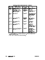
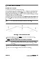
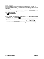
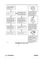
In this procedure, the ALC modulation oset and gain calibration constants are adjusted
to linearize the ALC modulator response to the ALC power level reference voltage. Default
values are entered for the modulator oset calibration constants and internal rmware is
activated to set the modulator gain calibration constants. The synthesizer is then set for a
power sweep across the entire leveled ALC range (020 to the maximum leveled power). The
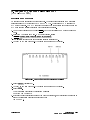
integrator level signal on the ALC board is monitored to verify linearity.
If necessary, the modulator oset values are modied.
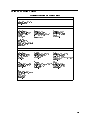
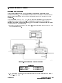
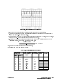
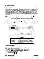
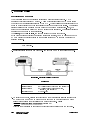
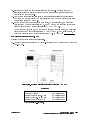
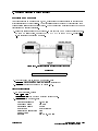
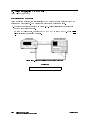
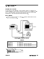
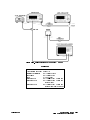
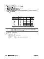
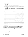
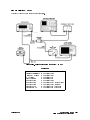
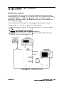
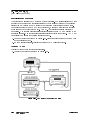
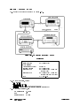
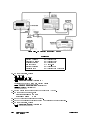
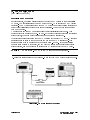
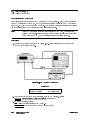
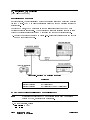
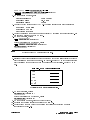
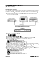
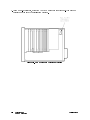
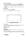
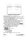
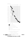
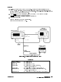
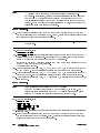
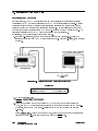
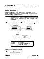
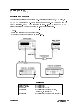
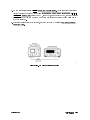
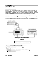
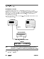
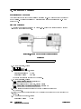
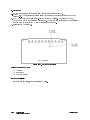
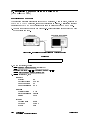
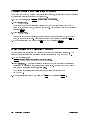
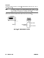
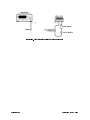
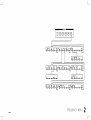
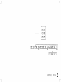
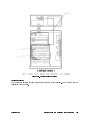
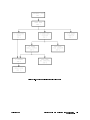
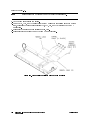
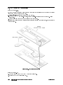
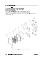
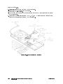
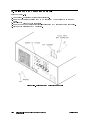
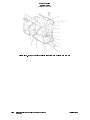
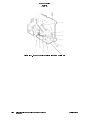
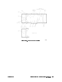
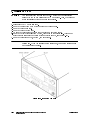
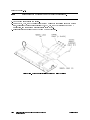
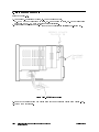
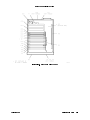
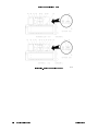
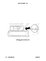
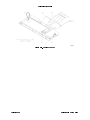
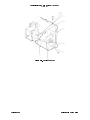
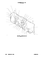
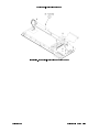
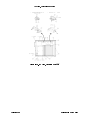
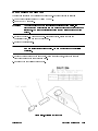
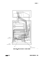
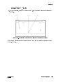
1. For 8360 B-Series only, connect the equipment as shown in Figure 3-23. Preset the
instruments and let them warm up for at least one hour. For 8360 L-Series, start this test
at step 2.
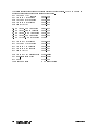
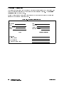
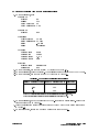
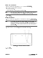
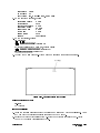
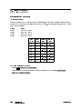
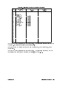
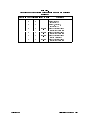
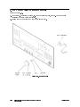
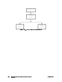
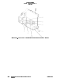
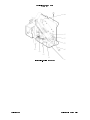
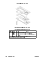
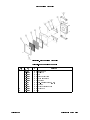
Figure 3-23. Modulator Offset and Gain Adjustment Setup
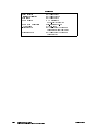
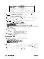
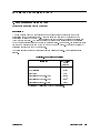
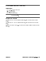
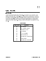
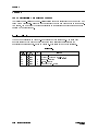
Equipment
Digitizing Oscilloscope
Oscilloscope Probes
HP/Agilent 54111D
HP/Agilent 10431A
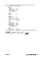
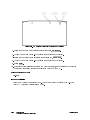
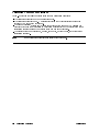
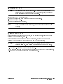
2. On the synthesizer, set:
4SERVICE5
NNNNNNNNNNNNNNNNNNNNNNNNNNNNNNNNNNN NNNNNNNNNNNNNNNNNNNNNNNNNNNNNNNN
Adjust Menu Calib Menu
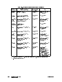
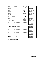
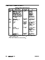
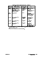
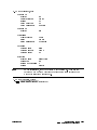
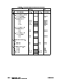
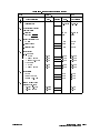
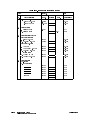
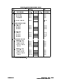
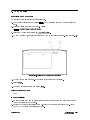
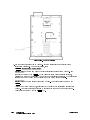
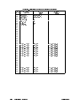
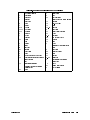
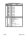
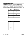
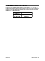
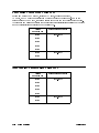
3. If you have replaced the low band assembly (A24) or the dual modulator assembly
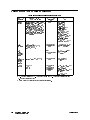
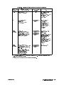
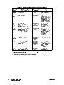
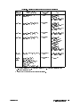
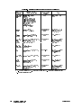
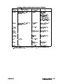
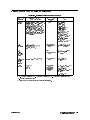
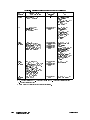
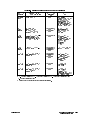
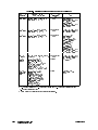
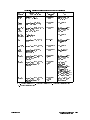
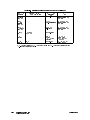
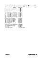
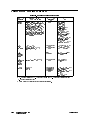
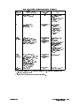
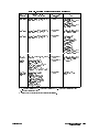
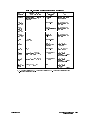
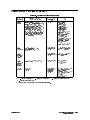
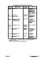
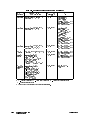
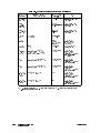
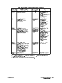
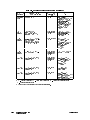
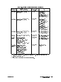
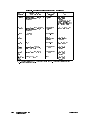
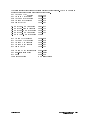
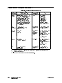
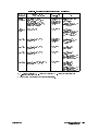
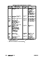
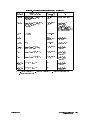
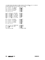
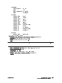
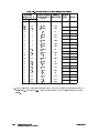
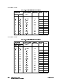
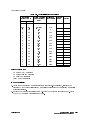
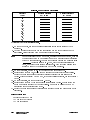
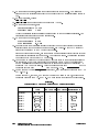
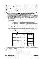
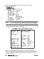
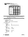
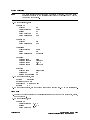
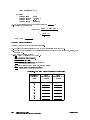
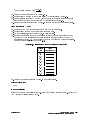
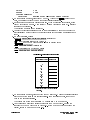
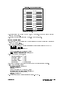
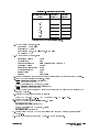
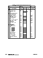
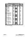
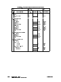
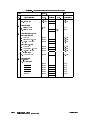
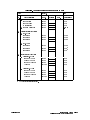
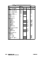
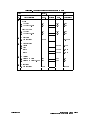
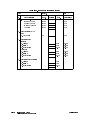
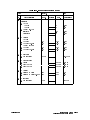
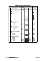
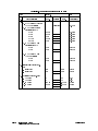
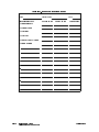
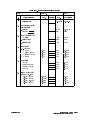
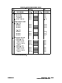
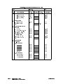
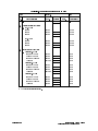
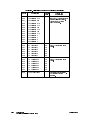
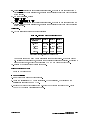
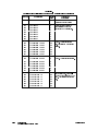
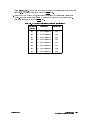
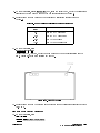
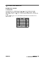
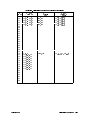
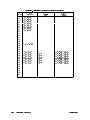
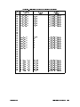
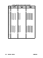
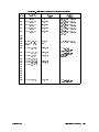
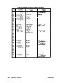
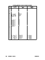
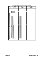
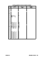
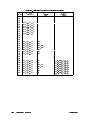
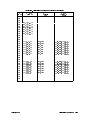
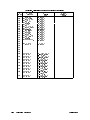
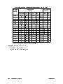
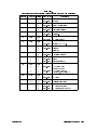
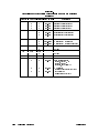
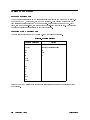
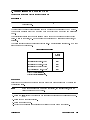
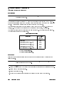
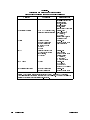
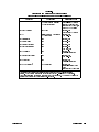
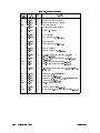
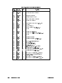
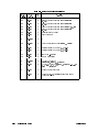
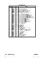
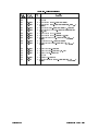
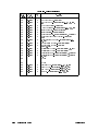
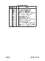
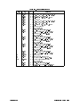
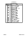
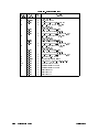
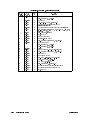
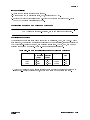
(A38), set the ALC oset calibration constants to the default values given in Table 3-6.
Otherwise, skip to step 7 for 8360 B-Series or skip to the next adjustment for 8360
L-Series.
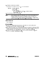
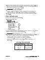
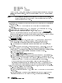
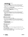
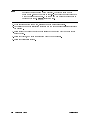
Select Select Cal . Using the numeric keypad, enter the number of the rst calibration
constant in Table 3-6. Terminate your entry with the 4ENTER5 key.
NNNNNNNNNNNNNNNNNNNNNNNNNNNNNNNN
3-62 Adjustments
Modulator Offset and Gain
Agilent 8360