1
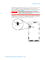
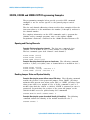
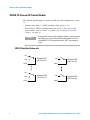
Agilent 34937A-34939A
General Purpose
Switch Modules
User’s Guide
Agilent Technologies, Inc.
Printed in Malaysia
Edition 1
June 2008 E0608
*34980-90037*
34980-90037
Agilent Technologies
Notices
© Agilent Technologies, Inc. 2008
Warranty
No part of this manual may be reproduced
in any form or by any means (including
electronic storage and retrieval or translation into a foreign language) without prior
agreement and written consent from
Agilent Technologies, Inc. as governed
by United States and international copyright laws.
Microsoft® and Windows® are U.S. registered trademarks of Microsoft Corporation.
The material contained in this document is provided “as is,” and is subject to being changed, without notice,
in future editions. Further, to the maximum extent permitted by applicable
law, Agilent disclaims all warranties,
either express or implied, with regard
to this manual and any information
contained herein, including but not
limited to the implied warranties of
merchantability and fitness for a particular purpose. Agilent shall not be
liable for errors or for incidental or
consequential damages in connection
with the furnishing, use, or performance of this document or of any
information contained herein. Should
Agilent and the user have a separate
written agreement with warranty
terms covering the material in this
document that conflict with these
terms, the warranty terms in the separate agreement shall control.
Software Revision
Technology Licenses
This guide is valid for the firmware that
was installed in the instrument at the time
of manufacture. However, upgrading the
firmware may add or change product
features. For the latest firmware and
documentation, go to the product page at:
The hardware and/or software described in
this document are furnished under a
license and may be used or copied only in
accordance with the terms of such license.
www.agilent.com/find/34980A
U.S. Government Restricted Rights.
Software and technical data rights granted
to the federal government include only
those rights customarily provided to end
user customers. Agilent provides this
customary commercial license in Software
and technical data pursuant to FAR 12.211
(Technical Data) and 12.212 (Computer
Software) and, for the Department of
Defense, DFARS 252.227-7015 (Technical
Data - Commercial Items) and DFARS
227.7202-3 (Rights in Commercial Computer Software or Computer Software
Documentation).
Manual Part Number
34980-90037
Edition
First Edition, June 2008
Printed in Malaysia
Agilent Technologies, Inc.
3501 Stevens Creek Blvd
Santa Clara, CA 95052 USA
ii
Safety Notices
CAUTION
A CAUTION notice denotes a hazard. It calls attention to an operating procedure, practice, or the like
that, if not correctly performed or
adhered to, could result in damage
to the product or loss of important
data. Do not proceed beyond a
CAUTION notice until the indicated
conditions are fully understood and
met.
WA R N I N G
A WARNING notice denotes a
hazard. It calls attention to an
operating procedure, practice, or
the like that, if not correctly performed or adhered to, could result
in personal injury or death. Do not
proceed beyond a WARNING
notice until the indicated conditions are fully understood and met.
Restricted Rights Legend
Agilent 34937A-34939A General Purpose Switch Modules User’s Guide
Additional Safety Notices
The following general safety precautions
must be observed during all phases of operation of this instrument. Failure to comply
with these precautions or with specific
warnings or instructions elsewhere in this
manual violates safety standards of design,
manufacture, and intended use of the
instrument. Agilent Technologies assumes
no liability of the customer’s failure to comply with the requirements.
General
Do not use this products in any manner not
specified by the manufacturer. The protective features of this product may be
impaired if it is used in a manner not specified in the operation instructions.
Do Not Modify the Instrument
Do not install substitute parts or perform
any unauthorized modification to the product. Return the product to an Agilent Sales
and Service Office for service and repair to
ensure that safety features are maintained.
In Case of Damage
Instruments that appear damaged or defective should be made inoperative and
secured against unintended operation until
they can be repaired by qualified service
personnel.
Safety Symbols
Before Applying Power
Alternating current
Verify that all safety precautions are taken.
Make all connections to the unit before
applying power.
Frame or chassis
terminal
Ground the Instrument
This product is provided with protective
earth terminals. To minimize shock hazard,
the instrument must be connected to the
ac power mains through a grounded power
cable, with the ground wire firmly connected to an electrical ground (safety
ground) at the power outlet. Any interruption of the protective (grounding) conductor or disconnection of the protective earth
terminal will cause a potential shock hazard that could result in personal injury.
Waste Electrical and Electronic
Equipment (WEEE) Directive
2002/96/EC
Standby supply. Unit is
not completely
disconnected from ac
mains when switch is off
Caution, risk of electric
shock
Caution, refer to
accompanying description
Do Not Operate in an Explosive
Atmosphere
Do not operate the instrument in the presence of flammable gases or fumes.
This product complies with the WEEE
Directive (2002/96/EC) marking requirement. The affixed product label (see above)
indicates that you must not discard this
electrical/electronic product in domestic
household waste.
Product Category: With reference to the
equipment types in the WEEE directive
Annex 1, this product is classified as a
“Monitoring and Control instrumentation”
product.
To return unwanted products, contact
your local Agilent office, or go to
www.agilent.com/environment/product
for more information.
Technical Support
If you have questions about your shipment,
or if you need information about warranty,
service, or technical support, contact
Agilent Technologies:
In the United States: (800) 829-4444
In Europe: 31 20 547 2111
In Japan: 0120-421-345
Or go to www.agilent.com/find/assist
for information on contacting Agilent in
your country of specific location. You can
also contact your Agilent Technologies
Representative.
Do Not Remove the Instrument
Cover
Only qualified, service-trained personal
who are aware of the hazards involved
should remove instrument covers. Always
disconnect the power cable and any external circuits before removing the instrument
cover.
Agilent 34937A-34939A General Purpose Switch Modules User’s Guide
iii
The Declaration of Conformity (DoC) for the 34980A mainframe
instrument can be found on page iii in the 34980A Mainframe User’s
Guide. That DoC applies to the 34980A mainframe and all available
plug- in modules.
iv
Agilent 34937A-34939A General Purpose Switch Modules User’s Guide
Contents
General Purpose Switch Modules . . . . . . . . . . . . . . . . . . . . . . . . . . . . . . . . . . . . . . . . . . . . . .1
Operating Considerations. . . . . . . . . . . . . . . . . . . . . . . . . . . . . . . . . . . . . . . . . . . . . . . . . . . . . .2
Electrical Considerations . . . . . . . . . . . . . . . . . . . . . . . . . . . . . . . . . . . . . . . . . . . . . . . . . . .2
Temperature Sensor. . . . . . . . . . . . . . . . . . . . . . . . . . . . . . . . . . . . . . . . . . . . . . . . . . . . . . . .2
Switching Reactive Loads. . . . . . . . . . . . . . . . . . . . . . . . . . . . . . . . . . . . . . . . . . . . . . . . . . .2
Hardware Power-Fail Jumper. . . . . . . . . . . . . . . . . . . . . . . . . . . . . . . . . . . . . . . . . . . . . . . .2
34937A, 34938A and 34939A SCPI Programming Examples . . . . . . . . . . . . . . . . . . . . . . . . .4
Opening and Closing Channels . . . . . . . . . . . . . . . . . . . . . . . . . . . . . . . . . . . . . . . . . . . . . .4
Reading Jumper State and System Identity. . . . . . . . . . . . . . . . . . . . . . . . . . . . . . . . . . . .4
Reading Cycle Count and Resetting Modules to Power-On State . . . . . . . . . . . . . . . . .5
34937A 32-Channel GP Switch Module . . . . . . . . . . . . . . . . . . . . . . . . . . . . . . . . . . . . . . . . . .6
34937A Simplified Schematic . . . . . . . . . . . . . . . . . . . . . . . . . . . . . . . . . . . . . . . . . . . . . . .6
34937A D-Sub Connectors . . . . . . . . . . . . . . . . . . . . . . . . . . . . . . . . . . . . . . . . . . . . . . . . . .7
34937T Terminal Block . . . . . . . . . . . . . . . . . . . . . . . . . . . . . . . . . . . . . . . . . . . . . . . . . . . . .8
34938A 20-Channel High-Current GP Switch Module . . . . . . . . . . . . . . . . . . . . . . . . . . . . . .9
34938A Simplified Schematic. . . . . . . . . . . . . . . . . . . . . . . . . . . . . . . . . . . . . . . . . . . . . . . .9
34938A D-Sub Connectors . . . . . . . . . . . . . . . . . . . . . . . . . . . . . . . . . . . . . . . . . . . . . . . . .10
34938T Terminal Block . . . . . . . . . . . . . . . . . . . . . . . . . . . . . . . . . . . . . . . . . . . . . . . . . . . .11
34939A 64-Channel High-Density Form-A GP Switch Module . . . . . . . . . . . . . . . . . . . . . .12
34939A Simplified Schematic . . . . . . . . . . . . . . . . . . . . . . . . . . . . . . . . . . . . . . . . . . . . . .12
34939A D-Sub Connectors . . . . . . . . . . . . . . . . . . . . . . . . . . . . . . . . . . . . . . . . . . . . . . . . .13
34939T Terminal Block . . . . . . . . . . . . . . . . . . . . . . . . . . . . . . . . . . . . . . . . . . . . . . . . . . . .15
Agilent 34937A-34939A General Purpose Switch Modules User’s Guide
v
vi
Agilent 34937A-34939A General Purpose Switch Modules User’s Guide
General Purpose Switch Modules
General Purpose Switch Modules
This User’s Guide covers the following two plug- in modules for the Agilent
34980A Multifunction Switch/Measure Unit:
34937A
34938A
34939A
28-channel Form C and 4-channel Form A
28-channel 5-amp Form A
64-Channel High-Density Form A
• The 34937A provides independent control of 32 relays, including:
• Twenty- eight Form C relays, each rated for 1 A at 60 W per channel
• Four Form A (SPST) relays, each rated for 5 A at 150 W per
channel.
• The 34938A, for power switching applications, offers 20 Form A relays,
each rated for 5 A at 150 W per channel.
• The 34939A provides independent control of 64 Form- A relays, each
rated for 1 A at 60 W per channel.
All three modules utilize armature- latching relays.
You can use these general- purpose switches in your 34980A mainframe for
device actuation, digital output, signal routing, or — combined with other
switch modules — to create flexible switching topologies. You can close
multiple channels at the same time. These modules do not connect to the
34980A’s analog buses.
Agilent 34937A-34939A General Purpose Switch Modules User’s Guide
1
Operating Considerations.
Operating Considerations.
WA R N I N G
Do not connect either the 34937A, 34938A or 34939A module
directly to a mains power outlet. If it is necessary to switch a mains
voltage or any circuit where a large inductive load may be
switched, you must add signal conditioning elements to reduce the
potential transients before they reach the module or the Analog
Buses.
Electrical Considerations
See the Introduction to the Plug In Modules chapter of the 34980A
Mainframe User’s Guide for detailed environmental operating conditions
for the 34980A mainframe and its installed modules. That guidance sets
maximum per channel current and power ratings at rated voltage for
pollution degree 1 (dry) and pollution degree 2 (possible condensation)
conditions, for each of the GP modules.
Temperature Sensor
A temperature sensor on these modules triggers system interrupts when
high- carry current- induced heat on the modules is excessive and sets the
HOT annunciator on the front panel. This over- temperature situation
generates an SRQ event when the factory- set 70 oC threshold is reached. It
is up to the user to determine what, if any, action should be taken.
Switching Reactive Loads
Reactive loads (those that include significant inductance or capacitance)
can cause voltage spikes or current spikes during switching operations.
The general purpose modules are designed for switching reactive loads.
The optional 34937T and 34938T terminal blocks have solder pads for
adding snubber circuits for the 5 A relays to reduce the reactive
transients. See the drawings on page 8 and page 11 for the locations of
snubber circuit pads and installation information about a snubber circuit.
Hardware Power-Fail Jumper
A hardware jumper on the 34937A and 34938A modules allows you to
define the power- failure states for the modules’ 5 A latching relays.
Depending on the position of the jumper, the 5 A relays will either open
or maintain state when system power failure occurs.
On the 34939A module, a hardware jumper allows you to define the
power- failure state affecting all 64 of the module’s 1 A latching relays.
Depending on the position of the jumper, these relays will either open or
maintain state when system power failure occurs.
2
Agilent 34937A-34939A General Purpose Switch Modules User’s Guide
Operating Considerations.
The jumpers are positionable across pins 1–2 (“Open” position) or across
pins 2–3 (“Maintain” position). When shipped from the factory, the
power- fail jumper is in the Maintain position (i.e. all relays maintain their
present state when power fails).
Before changing the position of the jumper, remove external
WA R N I N G
connections from the module. Wait five to ten seconds to allow the
module’s internal capacitors to discharge.
After a five- to ten- second delay, remove the sheet metal cover from the
module and move the position of the jumper mounted on the module. See
the figure below for the jumper’s location on the module.
Open
1
2
3
1
2
3
Maintain
U205
Power Down State
U301
Agilent 34937A-34939A General Purpose Switch Modules User’s Guide
C301
3
34937A, 34938A and 34939A SCPI Programming Examples
34937A, 34938A and 34939A SCPI Programming Examples
The programming examples below provide you with SCPI command
examples to use for actions specific to the general purpose switch
modules.
The slot and channel addressing scheme used in these examples follow the
form sccc where s is the mainframe slot number (1 through 8) and ccc is
the channel number.
For complete information on the SCPI commands used to program the
34980A, and for example programs, refer to the Agilent 34980A
Programmer’s Reference contained on the 34980A Product Reference CD.
Opening and Closing Channels
Example: Closing and opening channels The first two commands close
channel 3 for a module in slot 2, then channel 5 for that module.
The last command opens both channel 3 and channel 5.
ROUTe:CLOSe (@2003)
ROUTe:CLOSe (@2005)
ROUTe:OPEN (@2003,2005)
Example: Querying channels for open or closed state The following command
returns a 1 (true) or 0 (false) state of channel 016 for a module in slot 3.
ROUTe:CLOSe (@3016)
ROUTe:CLOSe? (@3016) !Returns a 1
ROUTe:OPEN? (@3016) !Returns a 0
Reading Jumper State and System Identity
Example: Querying the power-failure state of 5 A relays The following command
returns the position of the power- fail jumper, either “MAIN” (all relays
maintain their present state when power fails) or “OPEN” (all relays open
when power fails) for a module in slot 4. If this command is sent to a
module other than the 34937A or 34938A, “NONE” is returned (no error is
generated). In particular, the position of the power- fail jumper on the
34939A module cannot be queried using this commmand.
SYSTem:MODule:PFAil:JUMPer:AMP5? 4
Example: Querying the system for module identify (all modules) The following
command returns the identify of the module installed in slot 7.
SYSTem:CTYPe? 7
4
Agilent 34937A-34939A General Purpose Switch Modules User’s Guide
34937A, 34938A and 34939A SCPI Programming Examples
Reading Cycle Count and Resetting Modules to Power-On State
Example: Reading the cycle count for a relay (all switch modules) The following
command returns the relay cycle count on channel 7 and channel 16 for a
module in slot 1.
DIAGnostic:RELay:CYCLes? (@1007,1016)
Example: Clearing the cycle count for a relay (all switch modules) The following
command resets the relay cycle count on channels 7 and 16 for a module
in slot 1.
DIAGnostic:RELay:CYCLes:CLEar (@1007,1016)
Example: Resetting Module(s) to power-on state (all modules) The following
command resets a module in slot 4 to its power- on state.
SYSTem:CPON 4
Agilent 34937A-34939A General Purpose Switch Modules User’s Guide
5
34937A 32-Channel GP Switch Module
34937A 32-Channel GP Switch Module
The 34937A general- purpose switch module provides independent control
of:
• Twenty- eight Form C (SPDT) latching relays rated at 1 A
• Four Form A (SPST) latching relays rated at 5 A. You can set the
power- failure state for these 5 A relays (see “Hardware Power- Fail
Jumper” on page 2).
NOTE
A temperature sensor on these modules triggers system interrupts
when high-carry current-induced heat on the modules reaches a
threshold of 70 oC. See description of the “HOT” annunciator on
page 2.
34937A Simplified Schematic
NC
NO
Channel 001
(1A Form C)
COM
NO
Channel 029
(5A Form A)
COM
NC
NO
COM
6
Channel 028
(1A Form C)
NO
Channel 032
(5A Form A)
COM
Agilent 34937A-34939A General Purpose Switch Modules User’s Guide
34937A 32-Channel GP Switch Module
34937A D-Sub Connectors
Bank 1
Bank 1
For orientation, the D-sub connector end
of the module is facing you.
29NO 29C
1
7NO 3NO 12NO 8NO 4NO 1NO 13NO 9NO 5NO
2
3
Reserved 11C
18
19
4
5
34
35
Pin
42
25
8
46
29
12
38
21
4
6
7
8
9
10
2NO 14NO 10NO 30NO 30C
11
12
13
14
15
NC
16
17
7C
3C
12C
8C
4C
1C
13C
9C
5C
2C
14C
10C
6C
GND
20
21
22
23
24
25
26
27
28
29
30
31
32
33
3NC 12NC 8NC 4NC 1NC 13NC 9NC 5NC 2NC 14NC 10NC 6NC 6NO
GND 11NO 11NC 7NC
Channel
1 NC
1 Common
1 NO
2 NC
2 Common
2 NO
3 NC
3 Common
3 NO
Bank 2
36
38
37
Channel
4 NC
4 Common
4 NO
5 NC
5 Common
5 NO
6 NC
6 Common
6 NO
39
Pin
41
24
7
45
28
11
49
32
50
41
40
Channel
7 NC
7 Common
7 NO
8 NC
8 Common
8 NO
9 NC
9 Common
9 NO
43
42
Pin
37
20
3
40
23
6
44
27
10
44
45
47
46
Channel
10 NC
10 Common
10 NO
11 NC
11 Common
11 NO
12 NC
12 Common
12 NO
Pins
48
31
14
36
19
35
39
22
5
48
49
50
Channel
13 NC
13 Common
13 NO
14 NC
14 Common
14 NO
29 NO
29 Common
Pins
43
26
9
47
30
13
1
2
Channel
30 NO
30 Common
Reserved
GND
GND
No Connect
Pin
15
16
18
33
34
17
Bank 2
31NO 31C 21NO 17NO 26NO 22NO 18NO 15NO 27NO 23NO 19NO 16NO 28NO 24NO 32NO 32C
1
2
Reserved
3
25C
18
4
5
21C 17C
19
21
20
6
7
26C
22C
22
23
8
9
18C 15C
24
25
10
11
27C
23C
26
27
12
13
19C 16C
28
14
28C
29
15
24C 20C
30
31
NC
16
17
GND
32
50-Pin D-Sub
Male Connector
33
GND 25NO 25NC 21NC 17NC 26NC 22NC 18NC 15NC 27NC 23NC 19NC 16NC 28NC 24NC 20NC 20NO
34
Channel
15 NC
15 Common
15 NO
16 NC
16 Common
16 NO
17 NC
17 Common
17 NO
Pin
42
25
8
46
29
12
38
21
4
35
36
37
Channel
18 NC
18 Common
18 NO
19 NC
19 Common
19 NO
20 NC
20 Common
20 NO
38
Pin
41
24
7
45
28
11
49
32
50
41
42
Channel
21 NC
21 Common
21 NO
22 NC
22 Common
22 NO
23 NC
23 Common
23 NO
Pin
37
20
3
40
23
6
44
27
10
39
40
43
44
45
Channel
24 NC
24 Common
24 NO
25 NC
25 Common
25 NO
26 NC
26 Common
26 NO
Agilent 34937A-34939A General Purpose Switch Modules User’s Guide
46
Pins
48
31
14
36
19
35
39
22
5
47
48
49
Channel
27 NC
27 Common
27 NO
28 NC
28 Common
28 NO
31 NO
31 Common
50
Pins
43
26
9
47
30
13
1
2
Channel
32 NO
32 Common
Reserved
GND
GND
No Connect
Pin
15
16
18
33
34
17
7
34937A 32-Channel GP Switch Module
34937T Terminal Block
This terminal block with screw- type connections is labeled with the model
number and the abbreviated module name. In addition, space is available
on the label for you to write the slot number.
The 34980A Product Reference CD (shipped with the instrument) contains
a 34937T Wiring Log for you to document your wiring configuration for
this module. You can open the wiring log file in Microsoft® Excel® or
Adobe® Acrobat® format.
Wire Size:
20 AWG Typical
18 AWG Max
8
Pads for user-supplied snubber
circuity to alleviate reactive
transients. The circuits may
consist of resistors, capacitors,
varistors, or other elements as
needed to reduce the switching
voltage and current transients
inherent in reactive circuits.
Agilent 34937A-34939A General Purpose Switch Modules User’s Guide
34938A 20-Channel High-Current GP Switch Module
34938A 20-Channel High-Current GP Switch Module
The 34938A high- current GP switch module provides twenty 5 A Form A
(SPST) relays for general purpose switching needs. You can set the
power- failure state for these 5 A relays (see “Hardware Power- Fail
Jumper” on page 2).
NOTE
A temperature sensor on these modules triggers system interrupts
when high-carry current-induced heat on the modules reaches a
threshold of 70 oC. See description of the “HOT” annunciator on
page 2.
34938A Simplified Schematic
NO
Channel 001
(5A Form A)
COM
NO
Channel 020
(5A Form A)
COM
Agilent 34937A-34939A General Purpose Switch Modules User’s Guide
9
34938A 20-Channel High-Current GP Switch Module
34938A D-Sub Connectors
Bank 1
Bank 1
Bank 2
For orientation, the D-sub connector
end of the module is facing you.
6NO
6C
1NO
1C
7NO
7C
2NO
2C
3NO
3C
9NO
9C
4NO
4C
5NO
5C
NC
1
2
3
4
5
6
7
8
9
10
11
12
13
14
15
16
17
Reserved 1NO
18
19
GND 6NO
34
35
1C
7NO
7C
2NO
2C
3NO
3C
9NO
9C
4NO
4C
5NO
5C
GND
20
21
22
23
24
25
26
27
28
29
30
31
32
33
6C
7NO
7C
36
37
38
Channel
1NO
1Common
1NO
1Common
2NO
2Common
2NO
2Common
3NO
3Common
Pin
3
4
19
20
7
8
23
24
9
10
8NO
39
8C
8NO
8C
9NO
9C
4NO
40
41
42
43
44
45
Channel
3NO
3Common
4NO
4Common
4NO
4Common
4NO
4Common
5NO
5Common
Pin
25
26
13
14
29
30
45
46
15
16
Channel
5NO
5Common
6NO
6Common
6NO
6Common
7NO
7Common
7NO
7Common
50-Pin D-Sub
Male Connector
4C 10NO 10C 10NO 10C
47
46
Pin
31
32
1
2
35
36
5
6
21
22
48
49
50
Channel
7NO
7Common
8NO
8Common
8NO
8Common
9NO
9Common
9NO
9Common
Pins
37
38
39
40
41
42
11
12
27
28
Channel
9NO
9Common
10NO
10Common
10NO
10Common
Reserved
GND
GND
No Connect
Pins
43
44
47
48
49
50
18
33
34
17
Bank 2
16NO 16C 11NO 11C 17NO 17C 12NO 12C 13NO 13C 19NO 19C 14NO 14C 15NO 15C
1
2
3
4
5
6
7
8
9
10
11
12
13
14
15
Reserved 11NO 11C 17NO 17C 12NO 12C 13NO 13C 19NO 19C 14NO 14C 15NO 15C
18
19
21
20
22
24
23
25
27
26
28
29
30
31
NC
16
17
GND
32
50-Pin D-Sub
Male Connector
33
GND 16NO 16C 17NO 17C 18NO 18C 18NO 18C 19NO 19C 14NO 14C 20NO 20C 20NO 20C
34
35
36
Channel
11NO
11Common
11NO
11Common
12NO
12Common
12NO
12Common
13NO
13Common
10
37
Pin
3
4
19
20
7
8
23
24
9
10
38
39
40
41
Channel
13NO
13Common
14NO
14Common
14NO
14Common
14NO
14Common
15NO
15Common
42
Pin
25
26
13
14
29
30
45
46
15
16
43
44
45
Channel
15NO
15Common
16NO
16Common
16NO
16Common
17NO
17Common
17NO
17Common
46
Pin
31
32
1
2
35
36
5
6
21
22
47
48
49
Channel
17NO
17Common
18NO
18Common
18NO
18Common
19NO
19Common
19NO
19Common
50
Pins
37
38
39
40
41
42
11
12
27
28
Channel
19NO
19Common
20NO
20Common
20NO
20Common
Reserved
GND
GND
No Connect
Pins
43
44
47
48
49
50
18
33
34
17
Agilent 34937A-34939A General Purpose Switch Modules User’s Guide
34938A 20-Channel High-Current GP Switch Module
34938T Terminal Block
This terminal block with screw- type connections is labeled with the model
number and the abbreviated module name. In addition, space is available
on the label for you to write the slot number.
The 34980A Product Reference CD (shipped with the instrument) contains
a 34938T Wiring Log for you to document your wiring configuration for
this module. You can open the wiring log file in Microsoft® Excel® or
Adobe® Acrobat® format.
Wire Size:
20 AWG Typical
18 AWG Max
Pads for user-supplied snubber circuity to
alleviate reactive transients. The circuits may
consist of resistors, capacitors, varistors,
or other elements as needed to reduce the
switching voltage and current transients
inherent in reactive circuits.
Agilent 34937A-34939A General Purpose Switch Modules User’s Guide
11
34939A 64-Channel High-Density Form-A GP Switch Module
34939A 64-Channel High-Density Form-A GP Switch Module
The 34939A high- density GP switch module provides sixty- four 1 A Form
A (SPST) relays for general purpose switching needs. You can set the
power- failure state for these relays (see “Hardware Power- Fail Jumper” on
page 2).
NOTE
A temperature sensor on these modules triggers system interrupts
when high-carry current-induced heat on the modules reaches a
threshold of 70 oC. See description of the “HOT” annunciator on
page 2.
34939A Simplified Schematic
NO
Channel 001
(1A Form A)
COM
NO
Channel 064
(1A Form A)
COM
12
Agilent 34937A-34939A General Purpose Switch Modules User’s Guide
34939A 64-Channel High-Density Form-A GP Switch Module
34939A D-Sub Connectors
Bank 1
Bank 1
4C
4NO
1
7C
2
For orientation, the D-sub connector
end of the module is facing you.
7NO 10C 10NO 13C 13NO 16C 16NO 18C 18NO 21C 21NO 24C 24NO 27C 27NO 30C 30NO
3
4
5
6
3C
3NO
6C
6NO
9C
21
22
23
24
25
NC
5C
5NO
8C
40
41
42
43
44
1C
1NO
2C
60
61
62
63
Pin
62
61
64
63
22
21
2
1
42
41
24
23
4
3
7
8
9
10
11
12
13
14
15
16
17
18
20
19
9NO 12C 12NO 15C 15NO 19C 19NO 22C 22NO 25C 25NO 28C 28NO NC
26
27
28
30
29
31
32
33
34
35
37
36
38
78-Pin D-Sub
Male Connector
39
8NO 11C 11NO 14C 14NO 17C 17NO 20C 20NO 23C 23NO 26C 26NO 29C 29NO NC
NC
Channel
1 NO
1 Common
2 NO
2 Common
3 NO
3 Common
4 NO
4 Common
5 NO
5 Common
6 NO
6 Common
7 NO
7 Common
Bank 2
45
46
2NO NC
NC
NC
65
66
67
Description
8 NO
8 Common
9 NO
9 Common
10 NO
10 Common
11 NO
11 Common
12 NO
12 Common
13 NO
13 Common
14 NO
14 Common
Pin
44
43
26
25
6
5
46
45
28
27
8
7
48
47
64
49
48
47
50
51
GND Res. NC
68
69
Description
15 NO
15 Common
16 NO
16 Common
17 NO
17 Common
18 NO
18 Common
19 NO
19 Common
20 NO
20 Common
21 NO
21 Common
70
Pin
30
29
10
9
50
49
12
11
32
31
52
51
14
13
53
52
54
55
NC
NC
NC
NC
71
72
73
74
Description
22 NO
22 Common
23 NO
23 Common
24 NO
24 Common
25 NO
25 Common
26 NO
26 Common
27 NO
27 Common
28 NO
28 Common
Agilent 34937A-34939A General Purpose Switch Modules User’s Guide
Pin
34
33
54
53
16
15
36
35
56
55
18
17
38
37
56
57
58
59
32C 32NO 31C 31NO
75
76
77
Description
29 NO
29 Common
30 NO
30 Common
31 NO
31 Common
32 NO
32 Common
No Connect
No Connect
No Connect
No Connect
No Connect
No Connect
78
Pin
58
57
20
19
78
77
76
75
39
40
59
60
65
66
Description
No Connect
No Connect
No Connect
No Connect
No Connect
No Connect
Pin
67
70
71
72
73
74
Chassis GND 68
Reserved
69
13
34939A 64-Channel High-Density Form-A GP Switch Module
Bank 2
Bank 1
Bank 2
For orientation, the D-sub connector
end of the module is facing you.
58C 58NO 61C 61NO 52C 52NO 55C 55NO 46C 46NO 48C 48NO 39C 39NO 42C 42NO 33C 33NO 36C 36NO
1
2
3
4
5
6
7
8
9
10
11
12
13
14
15
16
17
18
20
19
57C 57NO 60C 60NO 51C 51NO 54C 54NO 45C 45NO 49C 49NO 40C 40NO 43C 43NO 34C 34NO NC
21
NC
22
26
25
27
28
30
29
31
32
33
34
35
37
36
38
39
59C 59NO 62C 62NO 53C 53NO 56C 56NO 47C 47NO 50C 50NO 41C 41NO 44C 44NO 35C 35NO NC
40
41
NC
42
44
43
45
46
NC
63
66
Channel
33 NO
33 Common
34 NO
34 Common
35 NO
35 Common
36 NO
36 Common
37 NO
37 Common
38 NO
38 Common
39 NO
39 Common
61
Pin
18
17
38
37
58
57
20
19
78
77
76
75
14
13
62
64
65
Description
40 NO
40 Common
41 NO
41 Common
42 NO
42 Common
43 NO
43 Common
44 NO
44 Common
45 NO
45 Common
46 NO
46 Common
Pin
34
33
54
53
16
15
36
35
56
55
30
29
10
9
49
48
47
63C 63NO 64C 64NO NC
60
14
24
23
78-Pin D-Sub
Male Connector
50
NC GND Res.
67
68
69
Description
47 NO
47 Common
48 NO
48 Common
49 NO
49 Common
50 NO
50 Common
51 NO
51 Common
52 NO
52 Common
53 NO
53 Common
51
53
52
54
55
NC
NC
NC
NC
NC
70
71
72
73
74
Pin
50
49
12
11
32
31
52
51
26
25
6
5
46
45
Description
54 NO
54 Common
55 NO
55 Common
56 NO
56 Common
57 NO
57 Common
58 NO
58 Common
59 NO
59 Common
60 NO
60 Common
Pin
28
27
8
7
48
47
22
21
2
1
42
41
24
23
56
57
58
59
38C 38NO 37C 37NO
75
76
77
Description
61 NO
61 Common
62 NO
62 Common
63 NO
63 Common
64 NO
64 Common
No Connect
No Connect
No Connect
No Connect
No Connect
No Connect
78
Pin
4
3
44
43
62
61
64
63
39
40
59
60
65
66
Description
No Connect
No Connect
No Connect
No Connect
No Connect
No Connect
Pin
67
70
71
72
73
74
Chassis GND 68
Reserved
69
Agilent 34937A-34939A General Purpose Switch Modules User’s Guide
34939A 64-Channel High-Density Form-A GP Switch Module
34939T Terminal Block
This terminal block with screw- type connections is labeled with the model
number and the abbreviated module name. In addition, space is available
on the label for you to write the slot number.
The 34980A Product Reference CD (shipped with the instrument) contains
a 34939T Wiring Log for you to document your wiring configuration for
this module. You can open the wiring log file in Microsoft® Excel® or
Adobe® Acrobat® format.
Wire Size:
20 AWG Typical
18 AWG Max
2
1
3
4
5
6
C NO C NO C NO C NO C NO C NO
34
33
35
36
37
38
C NO C NO C NO C NO C NO C NO
C NO C NO C NO C NO C NO C NO
8
7
9
10
11
12
C NO C NO C NO C NO C NO C NO
40
39
41
42
43
44
14
13
15
16
17
18
C NO C NO C NO C NO C NO C NO
46
45
47
48
49
50
C NO C NO C NO C NO C NO C NO
C NO C NO C NO C NO C NO C NO
20
19
21
22
23
24
C NO C NO C NO C NO C NO C NO
52
51
53
54
55
56
26
25
27
28
29
30
C NO C NO C NO C NO C NO C NO
C NO C NO C NO C NO C NO C NO
C NO C NO
C NO C NO
31
32
Agilent 34937A-34939A General Purpose Switch Modules User’s Guide
57
63
58
59
60
61
62
64
15
34939A 64-Channel High-Density Form-A GP Switch Module
16
Agilent 34937A-34939A General Purpose Switch Modules User’s Guide
Index
Index
Numerics
W
34929A
pinouts, 13
34937A
connector pinouts, 7
description, 1, 6
simplified schematic, 6
snubber circuitry, 8
terminal block, 8
wiring log, 8
34938A
connector pinouts, 10
description, 1, 9
simplified schematic, 9
snubber circuitry, 11
terminal block, 11
wiring log, 11
34939A
connector pinouts, 13
description, 1, 12
simplified schematic, 12
terminal block, 15
wiring log, 15
warranty, ii
C
connector pinouts
34937A, 7
34938A, 10
34939A, 13
D
D-sub pinouts
34937A, 7
34938A, 10
34939A, 13
J
jumper, 2
P
pinouts
34937A, 7
34938A, 10
34939A, 13
power-fail jumper, 2
programming examples, 4
T
temperature sensor, 2
Agilent 34937A-34939A General Purpose Switch Modules User’s Guide
17
Index
18
Agilent 34937A-34939A General Purpose Switch Modules User’s Guide