1
AcerNote Nuovo
User’s Manual
Copyright
Copyright © 1996 by Acer Incorporated. All rights reserved. No part of this
publication may be reproduced, transmitted, transcribed, stored in a retrieval
system, or translated into any language or computer language, in any form
or by any means, electronic, mechanical, magnetic, optical, chemical,
manual or otherwise, without the prior written permission of Acer
Incorporated.
Disclaimer
Acer Incorporated makes no representations or warranties, either expressed
or implied, with respect to the contents hereof and specifically disclaims any
warranties, merchantability or fitness for any particular purpose. Any Acer
Incorporated software described in this manual is sold or licensed “as is”.
Should the programs prove defective following their purchase, the buyer
(and not Acer Incorporated, its distributor, or its dealer) assumes the entire
cost of all necessary servicing, repair, and any incidental or consequential
damages resulting from any defect in the software.
Further, Acer
Incorporated reserves the right to revise this publication and to make
changes from time to time in the contents hereof without obligation of Acer
Incorporated to notify any person of such revision or changes.
Acer is a registered trademark of Acer Incorporated. Microsoft, MS-DOS, Windows and
Windows 95 are registered trademarks of Microsoft Corporation. IBM and OS/2 are registered
trademarks of IBM Corporation. Intel and Pentium are registered trademarks of Intel
Corporation. Other brand and product names are trademarks and/or registered trademarks of
their respective companies.
ii
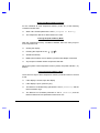
IMPORTANT SAFETY INSTRUCTIONS
1.
Read these instructions carefully. Save these instructions for future
reference.
2.
Follow all warnings and instructions marked on the product.
3.
Unplug this product from the wall outlet before cleaning. Do not use
liquid cleaners or aerosol cleaners. Use a damp cloth for cleaning.
4.
Do not use this product near water.
5.
Do not place this product on an unstable cart, stand, or table. The
product may fall, causing serious damage to the product.
6.
Slots and openings in the cabinet and the back or bottom are provided
for ventilation; to ensure reliable operation of the product and to protect
it from overheating, these openings must not be blocked or covered.
The openings should never be blocked by placing the product on a bed,
sofa, rug, or other similar surface. This product should never be placed
near or over a radiator or heat register, or in a built-in installation unless
proper ventilation is provided.
7.
This product should be operated from the type of power indicated on the
marking label. If you are not sure of the type of power available, consult
your dealer or local power company.
8.
Do not allow anything to rest on the power cord. Do not locate this
product where persons will walk on the cord.
9.
If an extension cord is used with this product, make sure that the total
ampere rating of the equipment plugged into the extension cord does
not exceed the extension cord ampere rating. Also, make sure that the
total rating of all products plugged into the wall outlet does not exceed
the fuse rating.
10. Never push objects of any kind into this product through cabinet slots as
they may touch dangerous voltage points or short out parts that could
result in a fire or electric shock. Never spill liquid of any kind on the
product.
iii
11. Do not attempt to service this product yourself, as opening or removing
covers may expose you to dangerous voltage points or other risks.
Refer all servicing to qualified service personnel.
12. Unplug this product from the wall outlet and refer servicing to qualified
service personnel under the following conditions:
a.
When the power cord or plug is damaged or frayed
b.
If liquid has been spilled into the product
c.
If the product has been exposed to rain or water
d.
If the product does not operate normally when the operating
instructions are followed. Adjust only those controls that are
covered by the operating instructions since improper adjustment of
other controls may result in damage and will often require
extensive work by a qualified technician to restore the product to
normal condition.
e.
If the product has been dropped or the cabinet has been damaged
f.
If the product exhibits a distinct change in performance, indicating
a need for service
13. Replace battery with the same type as the product's battery we
recommend. Use of another battery may present a risk of fire or
explosion. Refer battery replacement to a qualified serviceman.
14. Warning! Battery may explode if not handled properly. Do not
recharge, disassemble or dispose of in fire. Keep away from children
and dispose of used battery promptly.
15. Use only the proper type of power supply cord set (provided in your
accessories box) for this unit. It should be a detachable type: UL
listed/CSA certified, type SPT-2, rated 7A 125V minimum, VDE
approved or its equivalent. Maximum length is 15 feet (4.6 meters).
iv
Concerning Lithium Batteries
ADVARSEL!
Lithiumbatteri - Eksplosionsfare ved fejlagtig håndtering.
Udskiftning må kun ske med batteri
af samme fabrikat og type.
Lever det brugte batteri tilbage til leverandøren.
ADVARSEL
Eksplosjonsfare ved feilaktig skifte av batteri
Benytt samme batteritype eller en tilsvarende
type anbefalt av apparatfabrikanten.
Brukte batterier kasseres i henhold til fabrikantens
instruksjoner.
VARNING
Explosionsfara vid felaktigt batteribyte
Anvãnd samma batterityp eller en ekvivalent
typ som rekommenderas av apparattillverkaren.
Kassera anvãnt batteri enligt fabrikantens
instruktion
Canadian Department of Communications
Regulatory Statement
This digital apparatus does not exceed Class B limits for radio noise
emissions from digital apparatus set out in the Radio Interference
Regulations of the Canadian Department of Communications.
Le présent appareil numérique n'émet pas de bruits radio-électriques
dépassant les limites applicables aux appareils numériques de la classe B
prescrites dans le Réglement sur le brouillage radioélectrique édicté par le
ministère des Communications du Canada.
v
FCC Class B Radio Frequency Interference Statement
Note:
This equipment has been tested and found to comply with the limits for a
Class B digital device, pursuant to Part 15 of FCC Rules. These limits are
designed to provide reasonable protection against harmful interference in a
residential installation. This equipment generates, uses, and can radiate
radio frequency energy and, if not installed and used in accordance with the
instructions, may cause harmful interference to radio communications.
However, there is no guarantee that interference will not occur in a particular
installation. If this equipment does cause harmful interference to radio or
television reception, which can be determined by turning the equipment off
and on, the user is encouraged to try to correct the interference by one or
more of the following measures:
1.
Reorient or relocate the receiving antenna.
2.
Increase the separation between the equipment and receiver.
3.
Connect the equipment into an outlet on a circuit different from that to
which the receiver is connected.
4.
Consult the dealer or an experienced radio/television technician for
help.
Notice 1:
The changes or modifications not expressly approved by the party
responsible for compliance could void the user's authority to operate the
equipment.
Notice 2:
Shielded interface cables, if any, must be used in order to comply with the
emission limits.
vi
About This Manual
Purpose
This manual discusses the features of the notebook and tells how to use and
configure it.
Manual Structure
This manual consists of eight chapters and two appendices:
Chapter 1, Getting Started, tells you how to get started with the notebook.
Chapter 2, System Tour, gives a guided and in-depth “tour” of the notebook
and its features.
Chapter 3, Power, discusses issues on battery use and includes information
on the unique power management system.
Chapter 4, Options, tells how to connect and install hardware options.
Chapter 5, Software, describes how to configure certain utilities and
applications.
Chapter 6, Setup, explains how to configure the system with the BIOS Setup
utility.
Chapter 7, Traveling with the Notebook, includes informative and useful tips
on travel.
Chapter 8, Troubleshooting, lists the steps you can take to resolve problems
in an easy Q&A format.
Appendix A, Specifications, lists the specifications of the notebook.
Appendix B, Address and Interrupt Tables, shows the address and interrupt
tables.
vii
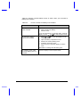
Conventions
The following conventions are used in this manual:
C:\setup,
[Enabled], etc.
message displayed
E,H,U, etc
Represent text input by the user, default settings
and recommended selections
Denotes actual messages that appear on screen
Represent the actual keys that you have to press
on the keyboard
NOTE
Gives bits and pieces of additional information
related to the current topic
WARNING
Alerts you if damage may result from doing or not
doing specific actions
CAUTION
Gives precautionary measures to avoid possible
hardware or software problems
IMPORTANT
Reminds you to take action relevant to the
accomplishment of the procedure at hand
TIP
Tells how to complete a procedure with minimum
steps through little shortcuts
viii
Ta b l e o f C o n t e n t s
1
2
Getting Started
1.1
Item Checklist............................................................................................1-2
1.2
Taking Care of Your Computer .................................................................1-3
1.2.1
Notebook ......................................................................................1-3
1.2.2
AC Adapter...................................................................................1-6
1.2.3
Battery Pack .................................................................................1-6
1.2.4
Cleaning and Servicing ................................................................1-7
1.2.5
Diskettes.......................................................................................1-7
1.3
Connecting the Notebook..........................................................................1-9
1.4
Creating Backup and Startup Diskettes ..................................................1-10
1.5
Getting Help Online .................................................................................1-11
System Tour
2.1
Features ....................................................................................................2-2
2.2
Display.......................................................................................................2-4
2.3
Indicator Lights ..........................................................................................2-7
2.4
Keyboard ...................................................................................................2-8
2.5
2.4.1
Keyboard Layout ..........................................................................2-8
2.4.2
Special Keys.................................................................................2-9
2.4.3
Automatic Tilt Feature ................................................................2-16
2.4.4
Palm Rest...................................................................................2-17
Touchpad ................................................................................................2-18
ix
2.6
2.7
2.8
2.9
Storage ................................................................................................... 2-20
2.6.1
Hard Disk ................................................................................... 2-20
2.6.2
Module Bay ................................................................................ 2-20
Ports ....................................................................................................... 2-23
2.7.1
Left Panel Ports ......................................................................... 2-23
2.7.2
Rear Panel Ports ....................................................................... 2-26
Audio....................................................................................................... 2-28
2.8.1
Built-in Speakers and Microphone............................................. 2-28
2.8.2
Controlling the Audio.................................................................. 2-29
Communications ..................................................................................... 2-30
2.9.1
Serial Infrared ............................................................................ 2-30
2.9.2
Fax/Data Modem ....................................................................... 2-31
2.10 Securing your Notebook ......................................................................... 2-32
2.10.1 Security Notch............................................................................ 2-32
2.10.2 System Resource Lock.............................................................. 2-32
3
Power
3.1
x
Battery Power ........................................................................................... 3-2
3.1.1
Battery Pack Characteristics........................................................ 3-2
3.1.2
Removing and Installing the Battery Pack ................................... 3-3
3.1.3
Charging the Battery.................................................................... 3-4
3.1.4
Checking the Battery Level .......................................................... 3-5
3.1.5
Optimizing Battery Life................................................................. 3-7
3.1.6
Battery Low Condition.................................................................. 3-8
3.2
4
Power Management ................................................................................3-10
3.2.1
The Concept of Heuristics..........................................................3-10
3.2.2
Suspend Modes .........................................................................3-11
3.2.3
Advanced Power Management (APM) .......................................3-14
Options
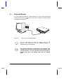
4.1
External Monitor ........................................................................................4-2
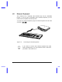
4.2
External Keyboard .....................................................................................4-3
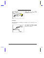
4.3
External Keypad ........................................................................................4-4
4.4
External Pointing Device ...........................................................................4-5
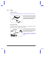
4.5
Printer ........................................................................................................4-7
4.6
Audio Devices ...........................................................................................4-8
4.7
Mini Dock...................................................................................................4-9
4.8
PC Cards...................................................................................................4-9
4.9
Miscellaneous Options ............................................................................4-10
4.9.1
Additional Power Packs..............................................................4-10
4.9.2
Cables ........................................................................................4-12
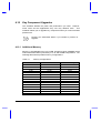
4.10 Key Component Upgrades ......................................................................4-14
4.10.1 Additional Memory......................................................................4-14
4.10.2 Hard Disk....................................................................................4-16
xi
5
Software
5.1
System Software....................................................................................... 5-2
5.2
Sleep Manager.......................................................................................... 5-3
5.3
5.2.1
Accessing the Sleep Manager ..................................................... 5-3
5.2.2
Sleep Manager Functions............................................................ 5-5
5.2.3
Running Sleep Manager .............................................................. 5-8
5.2.4
Sleep Manager Troubleshooting Tips.......................................... 5-9
5.2.5
Uninstalling Sleep Manager ....................................................... 5-10
Touchpad Driver ..................................................................................... 5-12
5.3.1
6
xii
Configuring the Touchpad ......................................................... 5-12
5.4
XingMPEG .............................................................................................. 5-13
5.5
Re-installing System Drivers and Applications ....................................... 5-14
Setup
6.1
When to Use Setup .................................................................................. 6-2
6.2
Entering Setup .......................................................................................... 6-3
6.3
About My Computer .................................................................................. 6-4
6.4
System Configuration ............................................................................... 6-7
6.4.1
Date and Time ............................................................................. 6-7
6.4.2
Diskette Drives............................................................................. 6-8
6.4.3
Hard Disks ................................................................................... 6-8
6.4.4
Num Lock After Boot ................................................................... 6-8
6.4.5
LCD Expansion Mode.................................................................. 6-8
6.4.6
Internal Cache ........................................................................... 6-10
6.4.7
External Cache .......................................................................... 6-11
6.4.8
Enhanced IDE Features .............................................................6-11
6.4.9
Onboard Communication Ports..................................................6-12
6.4.10 Onboard Audio ...........................................................................6-15
6.4.11 Reset PnP Resources ................................................................6-16
6.5
6.6
6.7
7
Power Saving Options .............................................................................6-17
6.5.1
When Lid is Closed ....................................................................6-18
6.5.2
Suspend to Disk on Critical Battery............................................6-19
6.5.3
Display Always On......................................................................6-19
6.5.4
Internal Speaker .........................................................................6-19
6.5.5
External Mouse Location............................................................6-19
6.5.6
Internal Modem ..........................................................................6-20
6.5.7
Resume On Modem Ring...........................................................6-20
6.5.8
Resume On Schedule ................................................................6-20
6.5.9
Resume Date / Resume Time....................................................6-20
System Security.......................................................................................6-21
6.6.1
Supervisor and User Passwords ................................................6-22
6.6.2
Diskette Drive Control ................................................................6-23
6.6.3
Hard Disk Drive Control..............................................................6-24
6.6.4
Start Up Sequences ...................................................................6-24
6.6.5
Flash New BIOS.........................................................................6-25
Reset to Default Settings.........................................................................6-26
Traveling with the Notebook
7.1
Travel Preparations ...................................................................................7-2
7.2
International Traveler’s Warranty ..............................................................7-3
7.3
Worldwide Support ....................................................................................7-4
xiii
8
Troubleshooting
8.1
Q & A ........................................................................................................ 8-2
8.2
POST Error Messages.............................................................................. 8-7
A
Specifications
B
Address and Interrupt Tables
xiv
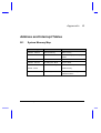
B.1
System Memory Map ................................................................................B-1
B.2
I/O Address Map.......................................................................................B-2
B.3
Interrupt Levels .........................................................................................B-3
B.4
DMA Channels..........................................................................................B-3
List of Figures
1-1
Write-protecting a 3.5-inch Diskette ..........................................................1-8
2-1
Display.......................................................................................................2-5
2-2
Indicator Lights ..........................................................................................2-7
2-3
Keyboard Layout .......................................................................................2-8
2-4
Palm Rest................................................................................................2-17
2-5
Touchpad ................................................................................................2-18
2-6
Module Bay..............................................................................................2-20
2-7
Left Panel Ports.......................................................................................2-23
2-8
Rear Panel Ports .....................................................................................2-26
2-9
Built-in Speakers and Microphone ..........................................................2-28
4-1
Connecting an External Monitor ................................................................4-2
4-2
Connecting an External Keyboard.............................................................4-3
4-3
Connecting an External Keypad ................................................................4-4
4-4
Connecting an External Pointing Device ...................................................4-5
4-5
Connecting a Parallel Printer.....................................................................4-7
4-6
Connecting Audio Devices ........................................................................4-8
4-7
Mini Dock...................................................................................................4-9
4-8
Using the File Transfer Cable..................................................................4-13
xv
L i s t o f Ta b l e s
2-1
Indicator Status Descriptions .................................................................... 2-7
2-2
Lock Key Descriptions .............................................................................. 2-9
2-3
Using the Embedded Keypad ................................................................. 2-10
2-4
Windows 95 Key Descriptions ................................................................ 2-11
2-5
Hot Key List............................................................................................. 2-12
2-6
Eject Menu Descriptions ......................................................................... 2-15
2-7
Touchpad Functions ............................................................................... 2-19
2-8
Left Panel Port Descriptions ................................................................... 2-24
2-9
Rear Panel Port Descriptions ................................................................. 2-27
2-10 Audio Control Hot Keys........................................................................... 2-29
xvi
3-1
Battery-level Chart .................................................................................... 3-6
3-2
Course of Action for Battery-low Condition ............................................... 3-9
4-1
Memory Configurations........................................................................... 4-14
4-2
Hard Disk List ......................................................................................... 4-16
5-1
Sleep Manager Window Items.................................................................. 5-4
5-2
Sleep Manager Error Messages and Solutions ........................................ 5-9
5-3
Location of Drivers.................................................................................. 5-14
5-4
Location of Applications .......................................................................... 5-15
6-1
About My Computer Item Descriptions ..................................................... 6-5
6-2
Diskette Drive Control Settings............................................................... 6-23
6-3
Hard Disk Drive Control Settings.............................................................6-24
6-4
Start Up Sequences Settings ..................................................................6-24
8-1
POST Error Messages ..............................................................................8-7
xvii
Chapter 1
Getting Started
Congratulations on your purchase of the award-winning AcerNote Nuovo
notebook computer. Guaranteed and backed by Acer’s world-class support,
you can be sure of top-notch performance with your new AcerNote. This
chapter guides you through the first few steps on setting up your notebook
computer.
Getting Started
1-1
1.1
Item Checklist
Carefully unpack the carton and remove the contents. If any of the following
items is missing or damaged, contact your dealer immediately.
•
Notebook computer
•
Accessory box
•
AC adapter
•
Battery pack
•
Floppy drive module
•
External floppy drive cable
•
User’s manual and other documentation
Check for optional items, if any.
1-2
User’s Manual
1.2
Taking Care of Your Computer
Your computer will serve you well if you take care of it. This section tells you
how to care for the notebook. Also, re-read the important safety instructions
at the beginning of this manual.
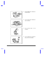
1.2.1
Notebook
•
•
Do not expose the notebook to
direct sunlight. Do not place
near sources of heat, such as a
radiator.
Do not expose to temperatures
below 0ºC (32ºF)
or
above 50ºC (122ºF).
Getting Started
1-3
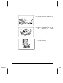
•
•
•
•
1-4
Do not subject the notebook to
magnetic fields.
Do not expose the notebook to
rain or moisture.
Do not spill water on the
notebook.
Do not subject the computer to
heavy shock and vibration.
User’s Manual
•
•
•
Getting Started
Do not expose the notebook to
dust and dirt.
Never place objects on top of
the
notebook
to
avoid
damaging the notebook.
Never place the notebook on
uneven surfaces.
1-5
1.2.2
AC Adapter
The AC adapter provides uninterrupted power to your notebook and charges
your battery pack. Here are some ways of taking care of your AC adapter.
•
•
•
1.2.3
Do not connect the adapter to any other device.
Do not step on the power cord or place heavy objects on top of it.
Carefully route the power cord and any cables away from personal
traffic.
When unplugging the power cord, pull on the plug and not on the cord
itself.
Battery Pack
The long-lasting Lithium-Ion (Li-Ion) rechargeable battery pack gives you
power on-the-go. Here are some things to keep in mind regarding your
battery pack.
Caution:
•
Replace the battery pack with the same type (Model Name: BTP-S31)
•
Battery pack is suitable for use only with this notebook model
•
•
•
1-6
Burn hazard. Do not disassemble. Handle damaged or leaking lithiumion battery with extreme care. If the battery is damaged, electrolyte may
leak from the cells and may cause personal injury.
There may be local restrictions on the disposal or recycling of batteries;
consult your local regulations or waste disposal provider.
Do not expose to high temperatures (50°C / 122°F)
User’s Manual
1.2.4
Cleaning and Servicing
When cleaning the notebook, follow these steps:
1.
Close the display lid to turn the notebook off.
2.
Disconnect the AC adapter.
3.
Remove the battery pack.
4.
Use a soft cloth moistened with water. Do not use liquid or aerosol
cleaners.
Contact your dealer or see your service technician if any of the following
occurs:
•
Notebook has been dropped or damaged.
•
Liquid has been spilled into the product.
•
The notebook does not operate normally.
See section 7.3 for contact information.
1.2.5
Diskettes
Following are some tips on diskette management:
•
•
•
Getting Started
Always make backup copies of diskettes that contain important data or
program files.
Keep diskettes away from magnetic fields and sources of heat.
Avoid removing a diskette from a drive when the floppy drive activity
light is on.
1-7
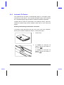
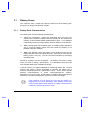
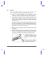
•
Write-protect your diskettes to prevent accidental erasure. To do this,
slide the write-protect tab to the write-protect position.
Write-protected
Not write-protected
Figure 1-1
•
1-8
Write-protecting a 3.5-inch Diskette
When you put a label on a 3.5-inch diskette, make sure that the label is
properly attached (flat on the surface) and within the labelling area (area
with slight surface depression) on the diskette. An improperly attached
label may cause a diskette to get stuck in the drive when you are
inserting or removing it.
User’s Manual
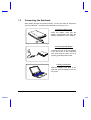
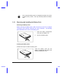
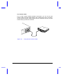
1.3
Connecting the Notebook
After reading through the previous section, you are now ready to experience
your new notebook. Connecting the notebook is as easy as 1-2-3.
Inserting the Battery Pack
Insert the battery pack into the
battery compartment and slide the
battery compartment cover in place.
Connecting the AC Adapter
Connect one end of the AC adapter
to the DC-in port on the notebook’s
rear panel and the other end to a
properly grounded power outlet.
Turning on the Power
Slide the display cover latch to the
right and open the display to turn on
the power.
Getting Started
1-9
1.4
Creating Backup and Startup Diskettes
Entering User Information
When Windows 95 loads for the first time, enter your user information. Have
your Windows 95 authentication number ready, found in the Windows 95
documentation package.
Creating Backup and Startup Diskettes
Windows 95 prompts you to create backup and startup diskettes.
If your Windows 95 package contains a Windows 95 CD-ROM,
you do not need to create backup diskettes for Windows 95.
However, you may need to create the Windows 95 startup disk.
At this point, you need to create the notebook backup disk which allows you
to boot-up your notebook from the floppy drive and access the CD-ROM
drive for Windows 95 and driver re-installation in case of a hard disk crash
(when the hard disk is not functioning properly and cannot be accessed) or
when your system cannot startup Windows 95. See the backup kit for
details.
If you do not wish to perform the backup at this time, you can skip through
this step during Windows 95 setup. Access the Create System Disk tool
when you wish to do so. However, we suggest you create the disk(s) as
soon as possible.
1-10
User’s Manual
1.5
Getting Help Online
This user’s manual provides clear and concise information about the
notebook, so read it thoroughly. To provide you with help when traveling, the
notebook has a comprehensive online help.
Accessing Online Help
Follow these steps to access the online documentation:
1.
Press the Windows logo button or Click on the Start button.
2.
Select Programs.
3.
Click on AcerNote Nuovo.
4.
Select Online Manual.
The online help is easy to navigate with hypertext and hypergraphics. Clear
illustrations help describe notebook operation as well.
Getting Online
If you are connected to the Internet and have World Wide Web access, visit
our home page (http://www.acer.com/) and get the latest information about
our products, as well as updates on software drivers and utilities.
Getting Started
1-11
Chapter 2
System Tour
This notebook combines high-performance, versatility, multimedia
capabilities and a truly advanced power management system in a unique
human-centric and stylish design case. Work with unmatched productivity
and reliability with your new power computing partner.
This chapter gives an in-depth “tour” of the notebook’s many features.
System Tour
2-1
2.1
Features
The notebook looks as good inside as it is outside, definitely designed with
the user in mind. Here are just a few of the notebook’s many features:
Performance
•
High-end mobile Pentium microprocessor
•
64-bit main memory and 256KB external (L2) cache memory
•
Large display in DualScan STN or active-matrix TFT
•
PCI local bus video with 128-bit graphics accelerator
•
Flexible module bay (3.5-inch floppy drive or CD-ROM drive)
•
High-capacity, Enhanced-IDE hard disk
•
•
Lithium-Ion smart battery pack
•
High speed connectivity
•
16-bit stereo audio with built-in FM synthesizer
•
Built-in microphone and dual angled stereo speakers
•
30fps (frames per second) full-screen, true-color MPEG video playback
•
Infrared wireless communication
•
1
2-2
Heuristic power management with suspend-to-memory and zero-volt
suspend-to-disk power-saving modes
1
Internal 28.8Kbps modem with DSVD (digital simultaneous voice over
data) support; with speakerphone and telephone answering device
features
This feature is available only in the U.S.
User’s Manual
Human-Centric Design and Ergonomics
•
Intuitive FlashStart automatic power-on
•
Sleek, smooth and stylish design
•
Automatic tilt-up, full-sized, full-function keyboard
•
Wide and comfortable palm rest
•
Ergonomically-centered touchpad pointing device
Expansion
•
PC Card (formerly PCMCIA) slots (two type II/I or one type III)
•
Mini dock option with built-in Ethernet
•
User-upgradeable memory
System Tour
2-3
2.2
Display
The large graphics display offers excellent viewing, display quality and
desktop performance graphics. The notebook supports two different
displays — DualScan STN or active-matrix TFT LCD.
Video Performance
PCI local bus video with 128-bit graphics acceleration boost your video to
desktop-performance level, and allows you to run 30fps full-screen, truecolor video playback via software MPEG.
Simultaneous Display
The notebook’s large display and multimedia capabilities are great for giving
presentations. If you prefer, you can connect an external monitor when
giving presentations as the notebook supports simultaneous display on the
LCD and external CRT. Simultaneous display allows you to control the
presentation from your notebook and at the same time face your audience.
For large-audience presentations, you can connect an LCD projection panel.
Power Management
The heuristic or “self-learning” power management system automatically
decides the best settings for your display while providing maximum
performance and power conservation. See section 3.2 for more information
on power management.
Opening and Closing the Display
To open the display, slide the display lid latch to the right and lift up the
display. Then tilt it to a comfortable viewing position. To close the display,
fold it down gently until the display lid latch clicks into place.
To avoid damaging the display, do not slam it when closing the
lid. Do not place any object on top of the notebook when the
display is closed.
2-4
User’s Manual
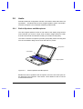
FlashStart Automatic Power-On
A noticeably unique feature about this notebook is that it has no on/off
switch. Instead it employs a lid switch, located near the center of the display
hinge, that tells the notebook when it should wake up or go to sleep.
Lid Switch
Figure 2-1
Display
When you close the display lid, the notebook enters suspend-to-memory or
suspend-to-disk mode before turning off the power, depending on the When
Lid is Closed parameter setting in Setup (see section 6.5.1). When you
open the lid, the notebook resumes from where you left off before closing the
lid.
Suspend-to-memory, suspend-to-disk and other power management issues
are discussed in detail in section 3.2.
System Tour
2-5
The “Lid Closed” State
When the lid is closed (i.e., the “lid closed” state), the notebook suspends its
normally busy tasks to make itself electronically and mechanically more
stable. When the lid is opened, the notebook briefly checks its environment
and always re-initializes devices newly added in or removed from the
notebook.
Though the notebook allows for various hot insertion of peripherals, the “lid
closed” state provides the most stable and practical means to attach and
detach peripheral components.
As a simple rule of thumb, close the lid when adding or
removing peripheral components.
2-6
User’s Manual
2.3
Indicator Lights
Two indicator lights are found on the display panel.
Power
Indicator
Battery
Indicator
Figure 2-2
Indicator Lights
These indicators and their descriptions are shown in Table 2-1.
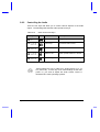
Table 2-1
Icon
Indicator Status Descriptions
Indicator Light
Description
Power Indicator
•
Lights when power is on
•
Flashes when the notebook is in suspend-tomemory mode
•
Lights when battery pack is charging
•
Flashes when battery power is low
Battery Indicator
To know more about batteries and power management, see Chapter 3.
System Tour
2-7
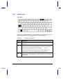
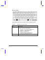
2.4
Keyboard
The full-sized keyboard includes an embedded keypad, separate cursor
keys, two Windows 95 keys and twelve function keys. Special keys are
highlighted in different colors.
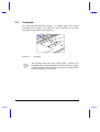
2.4.1
Keyboard Layout
US
UK
Figure 2-3
2-8
Keyboard Layout
User’s Manual
2.4.2
Special Keys
Lock Keys
The notebook has the three basic lock keys which you can toggle on and off.
as part of a key combination.
Some keys may require using
Table 2-2
Key
#
-
Lock Key Descriptions
Description
When Caps Lock is on, all alphabetical characters typed appear in
uppercase.
When Num Lock is on, the embedded keypad is in numeric mode. The
keys function as a numeric keypad like the one found on standard PC
keyboards (complete with arithmetic operators +, -, *, and /).
Use this mode when you need to do a lot of numeric data entry. A
better solution would be an external keypad. See section 4.3.
-
System Tour
When Scroll Lock is on, the screen moves one line up or down when
you press Z or \ respectively. Scroll lock does not work with some
applications.
2-9
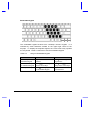
Embedded Keypad
The embedded keypad functions like a desktop numeric keypad. It is
indicated by small characters located on the upper right corner of the
keycaps. To simplify the keyboard legend, the cursor-control key symbols
are not printed. Table 2-3 tells how to use the embedded keypad.
Table 2-3
Using the Embedded Keypad
Desired Access
Num Lock On
Num Lock Off
Number keys on
embedded keypad
Type numbers in a normal
manner
Hold
while using
keypad keys
Cursor-control keys
on embedded keypad
Hold M while using
cursor-control keys
Hold
and M while
using cursor-control keys
Hold
while typing letters
on embedded keypad
Type the letters in a
normal manner
Main keyboard keys
2-10
User’s Manual
Windows 95 Keys
The keyboard has two keys that perform Windows 95-specific functions.
Table 2-4
Windows 95 Key Descriptions
Key
Description
Windows logo key
Start button. Combinations with this key performs special
functions. Below are a few examples:
•
•
•
•
•
•
Application Key
System Tour
Windows + Tab Activate next Taskbar button
Windows + E Explore My Computer
Windows + F Find Document
Windows + M Minimize All
Shift + Windows + M Undo Minimize All
Windows + R Display Run dialog box
Opens the application’s context menu (same as right-click).
2-11
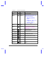
Hot Keys
The notebook uses hot keys (key combinations) to access most of the
notebook’s controls like screen contrast and brightness, volume output and
the BIOS setup utility. Some hot keys will pop-up a corresponding icon
onscreen for better visuals.
When activating hot keys, press and hold the first key
before pressing the other keys in the combination.
Table 2-5
Hot Key
Hot Key List
Icon
Function
Description
-_
Suspend-tomemory
Enters suspend-to-memory mode
-O
Help
Displays the hotkey list
Setup
Enters the BIOS setup utility
Plug and Play
Configuration
Allows the system to re-configure itself
and do self-diagnostics
Screen
Blackout
Blanks the screen to save power. To
wake up the screen, press any key.
?
-P
-Q
-R
2-12
PnP
User’s Manual
Table 2-5
Hot Key
System Tour
Hot Key List (continued)
Icon
Function
Description
-S
Display
Toggle
Switches display from LCD to CRT to
both LCD and CRT
-T
Fuel Gauge
On/Off
Toggles battery gauge display on/off.
Also shows the following:
•
“plug” icon if a powered AC
adapter is connected to the
notebook.
•
“speaker” icon if speaker output is
on (toggled by
-U).
•
“T” icon if turbo mode is on
(toggled by
-).
-U
Speaker
On/Off
Toggles speaker output on and off
-V
Lock System
Resources
Provides notebook security by locking
system from access. Requires
password input to unlock system. See
section 6.6.1.
-W
Eject
Accesses the Eject menu. See the
following subsection.
-E-Z
Volume Up
Increases audio volume
-E-\
Volume Down
Decreases audio volume
-E-]
Balance Left
Shifts speaker balance to the left
-E-[
Balance Right
Shifts speaker balance to the right
-
-Z
Brightness
Up
Increases screen brightness
-
-\
Brightness
Down
Decreases screen brightness to save
power
2-13
Table 2-5
Hot Key
Hot Key List (continued)
Icon
Function
Description
-
-[
Contrast Up
Increases screen contrast
(DSTN only)
-
-]
Contrast
Down
Decreases screen contrast
(DSTN only)
-Z
Fuel Gauge
Up
With the fuel gauge onscreen, moves
the fuel gauge up
-\
Fuel Gauge
Down
With the fuel gauge onscreen, moves
the fuel gauge down
-]
Fuel Gauge
Left
With the fuel gauge onscreen, moves
the fuel gauge left
-[
Fuel Gauge
Right
With the fuel gauge onscreen, moves
the fuel gauge right
-
CD Eject
Ejects the CD-ROM drive
-
Turbo Mode
On/Off
Toggles turbo mode on and off.
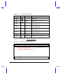
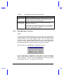
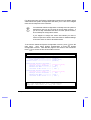
Using the Eject Menu
Pressing
-W brings up the Eject Menu.
Eject Menu
Battery (Suspend to Disk)..............
CD-ROM Disc (Also Fn+1)................
Power Off (Also Fn+BackSpace x3).......
Change
↑↓ = Move Highlight Bar, ↵ = Select, Esc = Exit
2-14
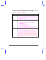
User’s Manual
The eject menu commands allow you to perform various eject-related
functions for the notebook. See the following table for details
Table 2-6
Eject Menu Descriptions
Select…
To…
Battery
Change the battery.
This option forces the notebook to enter suspend-to-disk mode,
so that you can replace the battery with a charged one, and then
return to where you left off.
To resume, close the display lid and open the display lid again.
CD-ROM Disc
Open the CD-ROM drive.
There are many ways to open the CD-ROM disc tray:
•
•
•
•
selecting this option
pressing Fn-1
pressing the CD-ROM eject button
using software controls
It is best to wait for the CD-ROM light (found on the CD-ROM
eject button) to go off before ejecting the CD-ROM drive.
Power Off
Turn the system off (without entering suspend mode).
When you choose this option, a “cold boot” occurs after restarting the system (closing and opening the display). You can
choose this option when you want to swap modules, or when
you want to turn off the notebook without entering any of the
suspend modes. Note however that the proper way to power off
the system in Windows 95 is to use the Shutdown command.
To turn the notebook back on, close the display lid and open the
display lid again.
System Tour
2-15
2.4.3
Automatic Tilt Feature
The keyboard has the option of automatically tilting to a six-degree angle
whenever you open the lid. This automatic tilt feature brings to the notebook
the comfortable typing angle provided in standard PC desktop keyboards.
Together with the palm rest (discussed in the following section), these two
ergonomic features help prevent repetitive strain injury to your wrists and
fingers.
Enabling and Disabling the Automatic Tilt Feature
A tilt switch, found right above the port cover on the rear of the notebook,
allows you to enable or disable this feature. Follow these steps:
1.
Close the lid.
2.
To enable the automatic tilt
feature, slide the tilt switch to
).
the right (
To disable the automatic tilt
feature, slide the tilt switch to
).
the left (
2-16
User’s Manual
3.
2.4.4
Open the lid.
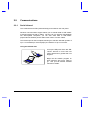
Palm Rest
Located below the keyboard, the wide and curved palm rest gives you a
comfortable place to rest your hands while you type.
Figure 2-4
System Tour
Palm Rest
2-17
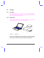
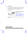
2.5
Touchpad
The ergonomically-centered touchpad is a pointing device that senses
movement on its surface. This means the cursor responds as you move
your finger on the surface of the touchpad.
Figure 2-5
Touchpad
The touchpad works with most mouse drivers. However, the
touchpad driver supports special functions that work uniquely
with the touchpad. We recommend you use the touchpad driver
instead of any other mouse driver.
2-18
User’s Manual
Touchpad Basics
The following two items teach you how to use the touchpad:
•
•
Move your finger across the touchpad to move the cursor.
Press the left and right buttons located on the lower edge of the
touchpad to do selection and execution functions. These two buttons
are similar to the left and right buttons on a mouse. Tapping on the
touchpad produces similar results. See Table 2-7.
Table 2-7
Touchpad Functions
Function
Left Button
Execution
Click twice
quickly
Tap twice (at the same speed as
double-clicking the mouse button)
Selection
Click once
Tap once
Drag
Click and
hold to drag
the cursor
Tap twice (at the same speed as
double-clicking the mouse button)
and hold finger to the touchpad on
the second tap to drag the cursor
Access
Context
Menu
Right Button
Click once
Tapping on the Touchpad
When Corner Taps is enabled, tap
on the upper right corner of the
touchpad. See section 5.3 on how
to configure the touchpad.
Keep your fingers dry and clean when using the touchpad. Also
keep the touchpad dry and clean.
The touchpad is sensitive to finger movements. Hence, the
lighter the touch, the better the response. Tapping too hard will
not increase the touchpad’s responsiveness.
System Tour
2-19
2.6
Storage
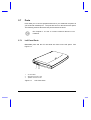
2.6.1
Hard Disk
High-capacity storage comes in the form of a 2.5-inch Enhanced-IDE hard
disk. The hard disk can be upgraded when you need more storage space.
See section 4.9.2 for related information.
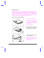
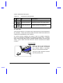
2.6.2
Module Bay
The notebook’s flexible module bay accommodates either a high-speed
CD-ROM drive module or a 3.5-inch, 1.44MB floppy drive.
CD-ROM Drive Module
Floppy Drive Module
Figure 2-6
Module Bay
The modules are designed to give you flexibility in the fast-moving portable
platform. The CD-ROM drive module gives you portable multimedia access.
The floppy drive module serves both as an internal and external unit.
2-20
User’s Manual
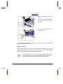
Swapping Modules
The proper way to cleanly swap or interchange modules is to power off the
notebook without the help of any suspend modes. The notebook needs to
perform a “cold boot” (Windows 95 shutdown or via the Eject menu) or
“warm boot” (Ctrl-Alt-Del) to correctly detect and identify the module currently
installed in the module bay. Simply closing the display lid will only put the
notebook in either suspend-to-disk or suspend-to-memory.
Follow these steps to swap modules:
1.
Do a Windows 95 shutdown.
If you are not using the
notebook under Windows 95,
you can use the Power-Off
option by accessing the Eject
Menu (Fn-F9).
System Tour
2.
Close the display lid.
3.
Slide the module release lock
and press the module release
latch and pull out the module.
4.
Insert the new module securely
into the module bay.
5.
Open the display lid.
After
opening
the
display,
the
notebook automatically senses
the new module.
2-21
Ejecting a CD
To eject a CD, press the eject button
-,
on the CD-ROM drive, press
or use your software to eject the
CD-ROM drive.
In Windows 95, you can right-click
on the CD-ROM drive icon and
select the Eject command.
Using the Floppy Drive Module Externally
You can use the floppy drive module externally when a CD-ROM drive
module is installed in the module bay.
You cannot use the CD-ROM drive module externally.
Only the floppy drive module can be used externally.
If the floppy drive module is installed
in the module bay, remove it by
following the steps described in the
previous section.
Open the port cover and connect the
25-pin connector end of the floppy
drive cable to the parallel port.
Connect the other end of the cable
to the floppy drive module.
2-22
User’s Manual
2.7
Ports
Ports allow you to connect peripheral devices to your notebook computer as
you would with a desktop PC. The ports are found on the left and rear panel.
The following sections discuss these ports and their functions.
See Chapter 4 on how to connect external devices to the
notebook.
2.7.1
Left Panel Ports
Multimedia ports and the PC card slots are found on the left panel. See
Figure 2-7.
1
1
2
3
PC Card Slots
Microphone-in/Line-in Port
Speaker-out/Line-out Port
Figure 2-7
System Tour
23
Left Panel Ports
2-23
Table 2-8 describes these ports.
Table 2-8
#
Icon
Left Panel Port Descriptions
Port
Connects to...
1
PC Card slots
One Type III or two Type I/II PC cards
2
Microphone-in/Line-in
External microphone or line input device
3
Speaker-out/Line-out
Amplified speakers or headphones
PC Card Slots
There are two type II/I or one type III PC Card slots found on the left panel of
the notebook. These slots accept credit-card-sized cards that enhance the
usability and expandability of the notebook.
PC Cards (formerly PCMCIA) are add-on cards for portable computers,
giving you expansion possibilities long afforded by desktop PCs. Common
type II cards include flash memory, SRAM, fax/data modem, LAN and SCSI
cards. Type III cards most often used are 1.8-inch ATA drives and cellular
modems.
Inserting a Card
Insert the card into the desired slot
and make the proper connections
(e.g., network cable), if necessary.
See your card manual for details.
For type III cards, insert the card into
the lower (bottom) slot.
2-24
User’s Manual
Ejecting a Card
1.
Exit the application using the
card.
2.
Flip out the slot eject button of
the slot where the card is
inserted.
3.
Press the slot eject button to
eject the card.
If you want to install a card, refer to your card’s user’s manual for details on
how to install and use the card.
Multimedia Ports
Connecting external audio devices to these ports automatically shuts off the
corresponding internal audio device. For example, if you connect external
speakers, the internal speakers automatically shut off.
To use Mic-in or Line in, insert the plug of the desired device
and make sure to turn off the appropriate input from the mixer.
See the multimedia section of your Windows 95 manual.
System Tour
2-25
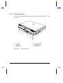
2.7.2
Rear Panel Ports
The rear panel includes the notebook’s main ports and connectors. See
Figure 2-8.
1
2
3
4
5
6
7
8
1
2
3
4
DC-in Port
PS/2 Port
Serial Port
Parallel Port
Figure 2-8
2-26
5
6
7
8
Mini Dock Connector
External CRT Port
RJ-11 Phone Jack
Infrared Port
Rear Panel Ports
User’s Manual
Table 2-9 describes these ports.
Table 2-9
#
Port
Connects to...
1
DC-in port
AC adapter and power outlet
2
PS/2 port
PS/2-compatible device
(e.g., PS/2 keyboard, keypad,
mouse)
3
Serial port
(UART16650-compatible)
Serial device
(e.g., serial mouse)
4
Parallel port
(EPP/ECP-compliant)
Parallel device (e.g., parallel
printer, external floppy drive)
5
Mini dock connector
Mini dock
6
External CRT port
External monitor
(up to 1024x768, 256 colors )
7
Modem jack (RJ-11)
Phone line
8
Infrared port
Infrared-aware device
(e.g., notebook with IR port,
desktop with IR adapter, IRcapable printer)
System Tour
Icon
Rear Panel Port Descriptions
2-27
2.8
Audio
Standard notebook configuration includes 16-bit stereo audio with built-in FM
synthesizer. Combined with the dual, angled speaker system and built-in
sensitive microphone, this notebook redefines portable audio.
2.8.1
Built-in Speakers and Microphone
The dual, angled speakers found on both sides of the display hinge directs
sound towards you, and its unique audio chamber design allows for better
acoustics and sound reverberation resulting in excellent sound quality.
The built-in sensitive microphone provides good quality audio recording with
its echo-cancellation design via the front-and-side mic pocket.
Microphone
Left Speaker
Right Speaker
Figure 2-9
Built-in Speakers and Microphone
Besides the built-in speakers and microphone, there are two audio ports on
the left panel of the notebook. See section 4.6 for details on how to connect
external audio devices.
2-28
User’s Manual
2.8.2
Controlling the Audio
There are hot keys that allow you to control various aspects of the audio
output. The following table lists the audio-specific hot keys:
Table 2-10
Audio Control Hot Keys
Hot Key
Icon
Function
Description
-U
Speaker On/Off
Toggles speaker output on and off
-E-Z
Volume Up
Increases audio volume
-E-\
Volume Down
Decreases audio volume
-E-]
Balance Left
Shifts speaker balance to the left
-E-[
Balance Right
Shifts speaker balance to the right
These settings are only in effect for a single session (e.g., up
to a power off). To let it stay in the same settings for the next
power on, you need to adjust the audio volume control in
Windows 95 or other operating systems.
System Tour
2-29
2.9
Communications
2.9.1
Serial Infrared
This notebook has an SIR (serial infrared) port located on the rear panel.
Wireless communication support allows you to transfer data to SIR-”aware”
machines without the aid of cables. Not only can you transfer data between
two SIR-capable computers, you can also send data to SIR-”aware”
peripherals like infrared printers without the need to connect cables.
The infrared port is IrDA-compliant, allowing it to transfer data with speeds of
up to 115.2 kilobits per second (kbps) at a distance of up to one meter.
Using the Infrared Port
Line up the SIR ports of the two SIR”aware” devices no more than one
meter apart and no greater than ±15
degrees.
Begin the file transfer program on
both machines and you’re ready to
go. See your file transfer software
manual for details.
2-30
User’s Manual
2.9.2
Fax/Data Modem1
The notebook has an optional state-of-the-art, 28.8Kbps V.34 fax/data
modem that supports V.42bis hardware compression (115.2 kilobits per
second). The modem also supports DSVD (simultaneous voice over data)
technology which allows you to send data and talk at the same time.
Using the Modem
Connect the phone line cable from
the RJ11 modem port on the
notebook’s rear panel to the
telephone line jack.
Begin your communications software
program. See your software manual
for instructions. The software also
supports
speakerphone
and
telephone answering device features.
The advantage of a built-in modem is that it frees up your PC card slots for
other functions.
1
This feature is available only in the U.S.
System Tour
2-31
2.10
Securing your Notebook
Security features include hardware and software locks — a security notch
and a two-level password scheme.
2.10.1 Security Notch
A security notch located on the left panel of the notebook lets you connect a
standard key-based computer security lock.
Circle or wrap a computer security
lock cable around an immovable
object such as a table or locked
drawer handle. Then insert the lock
into the notch and turn the key to
secure the lock.
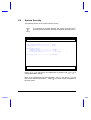
2.10.2 System Resource Lock
A two-level password scheme protects your notebook from unauthorized
access. When set, just press
-V to lock all system resources. In this
situation, no one can access the notebook without entering the correct
password.
For information on how to set passwords, see section 6.6.1.
2-32
User’s Manual
Chapter
3
Power
The notebook operates on AC or battery power. This chapter contains the
information you need to know to operate the notebook on battery power. The
chapter also includes information about the unique power management
system.
Power
3-1
3.1
Battery Power
The notebook uses a single high-capacity Lithium-Ion smart battery pack
that gives you longer use between charges.
3.1.1
Battery Pack Characteristics
The battery pack has the following characteristics:
•
•
•
Lithium-Ion Technology Lithium-Ion technology does not have the
memory effect problem of Nickel Cadmium (NiCd) nor the temperature
problem of Nickel Metal-Hydride (NiMH) battery types. Li-Ion batteries
consistently provide the longest battery life best-suited for road warriors.
Battery Gauge Built into the battery pack is a battery gauge that allows
you to check the battery charge level even when the battery is not
installed inside the notebook.
Battery-low Warning When the battery charge level becomes low, the
battery indicator flashes at regular intervals. This tells the user that the
battery power is very low. You can correct this situation by recharging
the battery pack.
Whenever possible, use the AC adapter. The battery will come in handy
when you travel or during a power failure. It is advisable to have an extra
fully-charged battery pack available for backup.
Currently, there is no defined standard for measuring battery life. Several
factors have made it almost impossible to compare the battery life of
different notebooks based on specifications alone. These factors include
different implementations of power saving/management systems,
applications in use, the user’s “usage pattern”, hard disk capacity and access
frequency, LCD size and brightness, system form factor and weight.
If the notebook is to be stored for more than two weeks, we
suggest that you remove the battery pack. Battery power from
a fully charged battery pack depletes in roughly a week with the
notebook in suspend-to-memory mode.
3-2
User’s Manual
Do not expose battery packs to temperatures below 0ºC (32ºF)
or above 60ºC (140ºF). This may adversely affect the battery
pack.
3.1.2
Removing and Installing the Battery Pack
Removing the Battery Pack
Before removing the battery pack, make sure that you have an AC adapter
connected to the notebook; otherwise turn off the notebook. The following
figure illustrates how to remove the battery pack.
1.
Press the battery compartment
cover latch and slide it out.
2.
Pull out the battery pack.
Installing the Battery Pack
Follow these steps to install the battery pack.
Insert the battery pack into the
battery compartment and slide in the
battery compartment cover.
Power
3-3
3.1.3
Charging the Battery
To charge the battery, place the battery pack inside the battery compartment
and plug the AC adapter into the notebook and an electrical outlet.
Charging Modes
The adapter has three charging modes:
•
Rapid charge mode
The notebook uses rapid charging when the notebook is in suspend
mode and a powered AC adapter is connected to it. In rapid mode, a
fully depleted battery gets fully charged in approximately two hours.
•
Charge-in-use mode
When the notebook is in use with the AC adapter plugged in, the
notebook also charges the battery pack if installed. This mode will take
longer to fully charge a battery than rapid mode. In charge-in-use
mode, a fully depleted battery gets fully charged in approximately four
hours.
•
Trickle charge mode
When the battery is fully charged, the adapter changes to trickle charge
mode to maintain the battery charge level. This prevents the battery
from draining while the notebook is in use.
We suggest that you charge the battery pack before you go to
sleep, letting it charge overnight before traveling. This ensures
a fully charged battery for use the next day.
3-4
User’s Manual
3.1.4
Checking the Battery Level
There are three ways to check the battery charge level:
•
Onscreen fuel gauge
•
Windows 95 battery indicator
•
Battery pack gauge
The fuel gauge shows the minimum guaranteed capacity to provide
assurance that the system will be operational for the minimum battery life
indicated.
Using the Onscreen Fuel Gauge
-T. If a powered AC adapter
To access the onscreen fuel gauge, press
is connected to the notebook, a plug icon also shows in the onscreen fuel
gauge.
and the cursor keys to move the fuel gauge around the
Press and hold
screen. The onscreen fuel gauge indicates the present battery level. Press
the hot key again to hide the fuel gauge.
Using the Windows 95 Battery Indicator
Rest your cursor on the battery icon on the taskbar to display the current
power left. Double-clicking on the battery icon on the taskbar displays the
Power dialog box. You can also access this dialog box via the Power icon
from the Control Panel.
When the notebook is running on AC power, a plug icon
replaces the battery icon on the taskbar.
Power
3-5
Using the Battery Pack Gauge
The battery pack gauge allows you to check your battery charge level even
when it is not installed in the notebook.
Press the fuel gauge button on the
battery pack to check the battery
charge level.
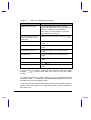
Table 3-1 is a battery-level chart.
Table 3-1
Battery-level Chart
Battery LEDs
zzzzz
zzzz{
zzz{{
zz{{{
z{{{{
{{{{
3-6
LEDs Lit
Charge Level
five
100%
four
≈80%
three
≈60%
two
≈40%
one
≈20%
one blinking
<20%
User’s Manual
3.1.5
Optimizing Battery Life
Optimizing battery life prolongs the charge/recharge cycle and improves
recharge efficiency. Follow these suggestions to optimize and maximize
battery power:
•
•
•
•
•
•
•
•
Power
Purchase an extra battery pack.
Set the When Lid is Closed parameter in Setup to [Suspend to
Disk]. See section 6.5.1.
Use the AC adapter whenever possible so that the battery is reserved
for on-the-go computing.
Keep the battery pack in the notebook powered by the AC adapter. The
constant trickle charge maintains the battery level to eliminate the
battery self-discharge effect. The charge-in-use function also charges
the battery pack.
Set the Internal Modem parameter to [Power-Off] to conserve
power when not using the internal modem. See section 6.5.6.
Set the Display Always On parameter to [Disabled] to save power.
See section 6.5.3.
Eject the PCMCIA card from the card slot when not in use, since the
PCMCIA card draws extra power.
Store the battery pack in a cool, dry place. The recommended storage
temperature for battery packs ranges from 10 to 30 degrees C. The
higher the storage temperature, the faster the battery pack selfdischarges.
•
The batteries can be recharged about 500 times when used as directed.
•
Take care of your battery pack. See section 1.2.3 for details.
3-7
3.1.6
Battery Low Condition
You never have to worry about battery power as long as you are using the
AC adapter. However, when you operate the notebook on battery power,
).
pay extra attention to the battery indicator (
Generally speaking, a battery-low condition occurs when less than twenty
percent charge left is in the battery. The following signals a battery-low
condition:
•
•
The battery indicator (
until AC power is applied
) flashes until battery power is depleted or
The fuel gauge (accessed via
-T) turns red
When you receive a battery-low warning, you have about fifteen minutes to
save your work. If you do not connect the AC adapter or install a backup
battery pack within fifteen minutes, the notebook enters suspend-to-disk
mode if the following conditions exist:
•
•
•
There is enough battery power left to save system information onto the
hard disk.
The suspend-to-disk file created by the Sleep Manager is present and
valid
All suspend-to-disk conditions are matched. See section 3.2.2.
Otherwise, the notebook enters suspend-to-memory mode.
Connect the AC adapter or insert a charged battery pack into
the notebook as soon as possible to prevent data loss.
3-8
User’s Manual
Table 3-2 lists the recommended course of action when you encounter a
battery-low condition.
Table 3-2
Course of Action for Battery-low Condition
Situation
Recommended Action
AC adapter and power
outlet available
1.
2.
Connect the AC adapter to the notebook to
begin charging the battery.
Resume work.
If you want the battery to recharge faster, close the
display or press
-_ ( ) to enter suspend mode.
An extra fully-charged
battery pack available
1.
2.
3.
4.
5.
Press
-_ ( ) or close the display to enter
suspend mode.
Open the battery compartment cover.
Remove the used up battery pack.
Install the new battery pack.
Press any key or open the display to resume
work.
Remember to recharge the old battery pack.
AC adapter, power outlet
and extra battery pack not
available
Power
Close the display to enter suspend mode.
3-9
3.2
Power Management
At the very heart of this notebook is a new way of power management called
Heuristic Power Management (HPM). Part of the notebook’s overall design,
this power management method allows the notebook to provide maximum
power conservation and maximum performance.
3.2.1
The Concept of Heuristics
Current power management schemes or methods used by notebooks are
timer-based. You have to set various time-out values for the display, the
hard disk and other devices. Then based on these fixed time-outs, the
system puts itself to sleep when it detects inactivity within this time frame.
The problem with this is — no two users are alike. Each individual user has
his or her own habits when using the computer. In short, timer-based power
management is not an effective way to power-manage a system.
Heuristics suggests an idea of “self-learning”. HPM allows the system to
power-manage itself depending on how you use the machine. In effect, the
notebook delivers maximum power when you need it and saves power when
you don’t need as much power, without requiring user intervention. There
are no timers to set, nothing to enable or disable, because the system
figures out everything for you.
Analogy on Heuristics
You normally walk to a grocery store. If you cross the street, you might have
to walk a bit faster, or even run. Whether you walk or run depends upon
situations that are not fixed.
The same should be true for computers. A computer should know when to
operate at full power and when to operate at anything less than full power.
Timer-based power management operates by a fixed set of rules which
cannot adapt to dynamic situations. Heuristic power management allows the
computer to adapt to dynamic situations.
3-10
User’s Manual
3.2.2
Suspend Modes
The heuristic power management system performs automatic suspend, hotkey suspend and all suspend actions resulting from various events and
conditions. You only need to set the suspend mode type the notebook
enters when a suspend condition occurs.
The two suspend modes are:
•
Suspend-to-memory mode
•
Suspend-to-disk mode
The suspend mode that the notebook enters into is specified in the When Lid
is Closed parameter in Setup. See section 6.5.1.
If an external monitor is connected to the notebook, the
notebook will not enter the desired suspend mode if you
close the display. To enter suspend mode, disconnect the
monitor plug, open the display and close the display again.
Suspend-to-Memory Mode
The notebook consumes very low power in suspend-to-memory mode. Data
remains intact in memory. The notebook restores this information from the
memory and resumes from where you left off upon leaving suspend mode.
When battery runs out of power and the AC adapter is not
connected, the notebook automatically does a suspend-to-disk
operation and ignores the When Lid is Closed parameter setting
in Setup. The suspend-to-disk file should be present and valid.
Power
3-11
Suspend-to-Memory Mode Conditions
For the notebook to enter suspend-to-memory mode, any of the following
conditions should exist:
•
When Lid is Closed parameter is set to [Suspend To Memory]
•
The suspend-to-disk file is either absent or invalid
Entering Suspend-to-Memory Mode
With the suspend-to-memory conditions satisfied, there are many ways to
enter suspend mode:
•
Closing the display
•
Pressing the suspend hot key
•
Sustained inactivity
•
Battery fail condition occurs without a powered AC adapter connected
•
Any suspend condition where suspend-to-disk fails
-_ (
)
When the system enters suspend-to-memory mode, the power indicator (
flashes.
)
Leaving Suspend-to-Memory Mode
There are four ways to leave suspend-to-memory mode and return to normal
mode:
•
If the display is closed, open the display
•
If the display is open, press any key.
•
•
3-12
The Resume on Modem Ring: parameter is set to [Enabled] and the
internal modem rings.
The Resume on Schedule parameter is set to [Enabled] and the
Resume Date and Time parameters have been met.
User’s Manual
Suspend-to-Disk Mode
In suspend-to-disk mode, power shuts off. The notebook saves all system
status information onto the hard disk (in a file created by Sleep Manager)
before entering suspend-to-disk mode. The next time you open the
notebook, it restores this information from the hard disk and resumes from
where you last left off.
Suspend-to-Disk Mode Conditions
For the notebook to enter suspend-to-disk mode, all of the following
conditions should exist:
•
•
•
When Lid is Closed parameter is set to [Suspend To Disk]
The suspend-to-disk file created by Sleep Manager is present and valid
The Resume on Modem Ring and Resume on Schedule parameters
are disabled. See sections 6.5.5 and 6.5.6.
Entering and Leaving Suspend-to-Disk Mode
With the suspend-to-disk conditions satisfied, there are four ways to enter
suspend-to-disk mode:
•
•
•
Closing the display
Battery fail condition occurs without a powered AC adapter connected
and Suspend to Disk on Critical Battery is set to [Enabled].
When battery is low while the notebook is in suspend-to-memory mode,
the notebook wakes up and performs a suspend-to-disk operation to
prevent data loss.
To leave suspend-to-disk mode, open the display. Make sure a charged
battery pack is installed and/or a powered AC adapter is connected before
you open the display.
Validating the Suspend-to-Disk File
To check if the suspend-to-disk file is present and valid, rest your cursor on
the Sleep Manager icon on the taskbar to show the status. See section 5.2
Power
3-13
3.2.3
Advanced Power Management (APM)
This notebook supports the APM standard designed to further reduce power
consumption. APM is a power-management approach defined jointly by
®
®
Microsoft and Intel . The notebook’s heuristic power management scheme
works hand-in-hand with APM to take advantage of power saving features
and allows greater system availability without degrading performance.
Advanced Power Management greatly prolongs battery life.
Use APM whenever possible.
Setting the Optimum Power Management Level
Follow these steps:
1.
Select the Start button, click on Settings... and select Control Panel.
2.
Double-click on the Power icon in the Control Panel window.
3.
Set the power management mode to Advanced for optimum power
management.
Enabling APM
If APM under Windows 95 is not enabled, follow these steps to enable it:
1.
Select the Start button, click on Settings... and select Control Panel.
2.
Double-click on the System icon in the Control Panel window.
3.
Select the Device Manager tab and double-click on System devices.
4.
Double-click on Advanced Power Management support to display its
properties. Select the Settings tab and make sure the check box for
enabling power management support is selected.
Refer to the Windows 95 user’s guide for details.
3-14
User’s Manual
Power
3-15
Chapter 4
Options
This notebook offers excellent connectivity and expansion capabilities with
its built-in ports and connectors. This chapter describes how to connect
1
peripherals and hardware options to the notebook. When connecting
peripherals, read the manual included with the peripheral for operating
instructions.
This chapter also includes information on the key components that you can
upgrade. Key component upgradeability gives you the room to enhance the
notebook to meet your future needs.
1
For complete options available, consult your dealer.
Options
4-1
4.1
External Monitor
To show graphical effects on a larger display, you can connect an external
) on the rear panel. Read the monitor manual
monitor to the CRT port (
for additional instructions.
Figure 4-1
Connecting an External Monitor
You can press
-S to toggle the display output to the
external CRT and back to the notebook display or
simultaneously on both displays.
If an external monitor is connected to the notebook, the
notebook will not enter the desired suspend mode if you
close the display. To enter suspend mode, disconnect the
monitor plug, open the display and close the display
again.
4-2
User’s Manual
4.2
External Keyboard
This notebook has a keyboard with full-sized keys and an embedded
keypad. If you feel more comfortable using a desktop keyboard, you can
install a PS/2-compatible external keyboard.
To connect an external keyboard, plug the external keyboard into the PS/2
).
connector (
Figure 4-2
Connecting an External Keyboard
If you need to connect both external keyboard and PS/2
mouse simultaneously, you can purchase a PS/2 Y-cable from
your dealer. See section 4.9.2.
Options
4-3
4.3
External Keypad
You can also use a 17-key numeric keypad for number-intensive data entry
applications. To connect the keypad, plug in the keypad connector to the
) at the rear of the notebook.
PS/2 port (
Figure 4-3
4-4
Connecting an External Keypad
User’s Manual
4.4
External Pointing Device
This notebook accepts either a serial mouse or PS/2-compatible mouse or
similar pointing device.
Connecting an External Pointing Device
If you use a serial mouse, plug it into the serial port (
) on the rear panel.
) on
If you use a PS/2-compatible mouse, plug it into the PS/2 port (
the rear panel. Installing an external PS/2 mouse automatically disables the
built-in touchpad.
(a) Serial Mouse
(b) PS/2 Mouse
Figure 4-4
Options
Connecting an External Pointing Device
4-5
Setting the External Mouse Location Parameter
After connecting the external mouse or similar pointing device, press -P
to enter Setup and verify the location of the external pointing device. Select
Power Saving Options to display the following screen:
Power Saving Options
Page 1/1
When Lid is Closed ------------------ [ Suspend to Disk ]
Suspend to Disk on Critical Battery - [Enabled ]
Display Always On ------------------Internal Speaker -------------------External Mouse Location ------------Internal Modem ----------------------
[Disabled]
[Enabled ]
[PS/2]
[Power-Off]
Resume On Modem Ring ---------------Resume On Schedule -----------------Resume Date --------------------Resume Time ---------------------
[OFF]
[OFF]
[12/31/99]
[23:59:00]
↑ ↓ = Move Highlight Bar, → ← = Change Setting
PgDn/PgUp = Move Screen, F1 = Help, Esc = Exit
Go to the External Mouse Location parameter and select COM1 if you
connected your mouse to the serial port, and PS/2 if you connected your
mouse to the PS/2 port.
The External Mouse Location parameter setting allows the
notebook’s power management system to detect activity from
the external pointing device. If you are using an external
pointing device, make sure this parameter is set correctly.
4-6
User’s Manual
4.5
Printer
This notebook supports both serial and parallel printers. For a serial printer,
). For a parallel printer, plug the
plug the printer cable into a serial port (
printer cable into the parallel port ( ). See your printer manual for operating
instructions.
Figure 4-5
Options
Connecting a Parallel Printer
4-7
4.6
Audio Devices
You can connect audio devices to the line-in and line-out ports on the
notebook. The line-in audio port doubles as a microphone-in port as well.
The line-in port accepts an external 3.5mm mini-jack microphone or other
line-in devices. The line-out port accommodates external amplified speakers
or headphones.
Figure 4-6
Connecting Audio Devices
To use Mic-in or Line in, insert the plug of the desired device
and make sure to turn off the appropriate input from the mixer.
See the multimedia section of your Windows 95 manual.
4-8
User’s Manual
4.7
Mini Dock
The mini dock serves as a docking base that allows you to connect your
notebook to all the peripherals you need, even network connections with its
built-in Ethernet support. Consult your dealer for details. A quick guide is
included with the mini dock for easy and quick connection instructions.
Figure 4-7
4.8
Mini Dock
PC Cards
The notebook has two PC card slots that accommodate two type I/II or one
type III PC card(s). Please consult your dealer for PC card options available
that you can purchase for your notebook.
Options
4-9
4.9
Miscellaneous Options
4.9.1
Additional Power Packs
Lithium-Ion Battery Pack
It is good practice to have a spare battery pack around, especially when you
travel. The Li-Ion (lithium-ion) smart battery supplies more power than a
conventional NiMH (nickel metal-hydride) battery. With power management,
you get even more power on-the-go.
Attaching the Battery Compartment Cover
Each battery pack comes attached with a battery compartment cover. In
case the cover gets detached, follow these steps to re-attach the cover to the
battery.
1. Position the battery compartment
cover over the battery pack.
2. Using a little force, slide the
battery compartment cover over
the battery until both the cover
and the battery are firmly
attached.
4-10
User’s Manual
Detaching the Battery Compartment Cover
Gently
pull
up
the
battery
compartment cover release latch
and slide out the cover.
AC Adapter
You can purchase an additional AC adapter for your notebook or mini
docking station.
The compact AC adapter charges
your battery pack and supplies
power to your notebook.
Options
4-11
4.9.2
Cables
Floppy Drive Cable
The floppy drive cable allows you to use your floppy drive module externally.
Open the port cover of the notebook
and connect the 25-pin connector
end of the floppy drive cable to the
parallel port. Then connect the other
end to the floppy drive module.
PS/2 Y-Bridge Cable
The PS/2 Y-bridge cable allows you to connect two PS/2 devices, mouse
and keyboard, to your notebook simultaneously.
Connect the single connector end of
the Y-bridge cable to the notebook’s
PS/2 port and the double connector
ends to the two PS/2 devices.
Take note of the icons on the double
connector before connecting the
devices.
4-12
User’s Manual
File Transfer Cable
For non SIR- (serial infrared) capable connections, you can use the file
transfer cable to transfer data between the notebook and other computers.
Connect the file transfer cable between the two computers and use your file
transfer utility to perform the transfer.
Figure 4-8
Options
Using the File Transfer Cable
4-13
4.10
Key Component Upgrades
This notebook delivers the power and performance you need. However,
some users and the applications they use may demand more. This
notebook allows you to upgrade key components when you need increased
performance.
Contact your authorized dealer if you decide to perform an
upgrade.
4.10.1 Additional Memory
Memory is upgradeable from 8 to 64 MB, employing 64-bit soDIMMs (small
outline Dual Inline Memory Modules) in 8, 16 and 32 MB configurations. The
following table lists all possible memory configurations.
Table 4-1
Slot 1
0 MB
8 MB
8 MB
0 MB
16 MB
8 MB
16 MB
16 MB
0 MB
32 MB
8 MB
32 MB
16 MB
32 MB
32 MB
4-14
Memory Configurations
Slot 2
8 MB
0 MB
8 MB
16 MB
0 MB
16 MB
8 MB
16 MB
32 MB
0 MB
32 MB
8 MB
32 MB
16 MB
32 MB
Total Memory
8 MB
8 MB
16 MB
16 MB
16 MB
24 MB
24 MB
32 MB
32 MB
32 MB
40 MB
40 MB
48 MB
48 MB
64 MB
User’s Manual
Installing Memory
When installing memory, we recommend you seek the help of a
qualified service technician. Improper installation may damage
the memory module or the notebook, or cause a malfunction.
One of the two memory slots (Slot 2) is accessible via a memory expansion
door on the base of the notebook. Follow these steps to install an additional
memory module.
Options
1.
Press -W to access the eject
menu and select the “Hardware
Service” option. Press H.
2.
Close the display lid.
3.
Turn the notebook
access the base.
4.
Remove the screw that secure
the memory door and lift it up.
5.
(1) Insert the memory module
diagonally into the slot, then (2)
gently press down the module
until it clicks into place.
over
to
4-15
6.
Replace the memory door and
secure it with the screws.
7.
Open the display to turn on the
notebook.
After new memory modules have been installed, the system automatically
detects and reconfigures the total memory size.
To upgrade memory installed in the other slot (Slot 1), contact your dealer.
4.10.2 Hard Disk
You can have your hard disk upgraded to one with a higher capacity. The
notebook uses a 2.5-inch Enhanced-IDE hard disk that is auto-detected by
the system. The following table shows the currently supported hard disks.
Table 4-2
Hard Disk List
Vendor
Model
Capacity
Cylinders
Heads
Sectors
IBM
DPRA-21215
1.2 GB
2358
16
63
IBM
DMCA-21440
1.44 GB
2800
16
63
IBM
DCRA-22160
2.0 GB
4200
16
63
Consult your dealer for additional hard disks that will be available in the
future. You may use the empty spaces in the table to record these additional
drives and their information.
4-16
User’s Manual
Options
4-17
Chapter 5
Software
This notebook comes pre-loaded with application software and system
utilities. This chapter discusses some of these applications and how to
make use of them.
Software
5-1
5.1
System Software
1
The notebook comes preloaded with the following software :
•
Windows 95 or other operating systems
•
System utilities and applications
•
Suspend-to-disk utility (Sleep Manager)
•
Touchpad driver
•
Display driver
•
Audio driver
•
Modem driver and application
•
System core logic driver
•
File-transfer utility
•
PC Card slot driver and application
•
Software MPEG driver and player
•
Other application software
2
The following sections discuss the software and how they work. For most of
the software, make use of the online help provided by the software.
Accessing the Applications
To access most of the software applications, click on the Start button and
select the application folder. Then click on the application icon to run the
selected application.
1
2
5-2
The pre-loaded software may differ.
The modem driver and software are optimized for use only with the internal modem, and may not
function properly with a different modem. For PCMCIA modems, use the software that came with
your PC card modem. This driver is only preloaded on notebooks for the U.S. market.
User’s Manual
5.2
Sleep Manager
Notebooks usually feature built-in power-saving functions. In addition to the
normal standby mode for power-saving, our notebooks are also capable of a
power management feature called 0-volt suspend to hard disk. When a
suspend event occurs, this built-in function saves all the system’s current
status onto your hard disk in the form of a file. The system then shuts off the
power. When the user resumes (e.g., opening the display), the system will
restore the data from the hard disk and resume from where you left off upon
leaving suspend mode.
Sleep Manager is a utility that reserves hard disk space needed to
successfully perform the suspend-to-disk feature. The user can use this
utility to create a contiguous area that resides on the hard disk. Once the
reserved space is created, the notebook will be capable of the “0-Volt
Suspend to Hard Disk” feature. User can also use this utility to remove the
reserved space from the disk. In this case, the machine will not be able to
enter 0-volt suspend mode.
Sleep Manager is functionally-connected with the Advanced Power
Management (APM) system of Microsoft Windows. Sleep Manager uses
many advanced APM functions. Sleep Manager is capable of auto-create
and auto-recover features. If the system memory size was changed or the
reserved space on the hard disk was corrupted, Sleep Manager will
reallocate the hard disk space for you automatically.
5.2.1
Accessing the Sleep Manager
There are two ways to bring up the Sleep Manager:
Software
•
Taskbar. Double-click on the Sleep Manager status icon if enabled.
•
Start menu
1.
Click on the Start button.
2.
Select Programs.
3.
Select 0V Suspend Utility.
4.
Select Sleep Manager.
5-3
The Sleep Manager displays below:
Table 5-1
Sleep Manager Window Items
Item
Description
Buttons
Click to access the Sleep Manager functions
Current Setting
Displays the drive and size of the current reserved space
created by Sleep Manager.
On Board
Information
Displays the different areas of system memory and their
respective values. These system resources need to be stored
before the system can enter 0-volt suspend mode, so the system
can resume to the previous state successfully.
These system resources are the contents of:
•
•
•
•
Onboard memory (DRAM or dynamic memory)
Video RAM (VRAM or video memory)
SMRAM (static memory)
Others
The total size of these system resources is displayed as the
recommended size in the dialog box.
5-4
User’s Manual
Table 5-1
Sleep Manager Window Items (continued)
Item
Description
Recommended
Size
Displays the minimum size of the contiguous space you need for
the 0-volt suspend-to-disk feature. The actual size may be a
little bit more due to file system alignment.
Enable Indicator
on the Taskbar
When this checkbox is checked, the Sleep Manager status
appears on the taskbar.
Double-click on the Sleep Manager status icon on the taskbar to
bring up the main program, or simply rest your mouse pointer on
the icon to display the current status.
5.2.2
Sleep Manager Functions
Create
The main purpose of Sleep Manager is to find and reserve a contiguous area
on the hard disk. The user can allocate the space themselves by using the
‘Create’ function on the Sleep Manager utility. Once a suspend event
occurs, the system will enter the suspend mode. If the user did not create
the space or the system DRAM size been changed, Sleep Manager is
invoked and begins the process of creating a space for the system.
When you click on the Create button, a dialog box pops up:
You can select OK to automatically create space for the 0-volt suspend
feature. Sleep Manager displays the recommend size based on onboard
system information. You can also choose Advance>>> to manually set the
space settings and size. The advanced screen shows.
Software
5-5
Sleep Manager automatically checks the system configuration and displays
the recommended size. The drive where the space will be created is defined
by the system and will be the first available logical drive which has the
requested contiguous free disk space on it. The recommended size is the
minimum size needed to save the current system status.
If the program cannot find the required space on the hard disk during the
space creation process, it shows a message box to inform the user.
Not Enough Space for Allocation
This is a common error message that appears when Sleep Manager is
creating the space on the hard disk. There are several different reasons that
may cause this error. One of the reasons is that the size of the free disk
space on the specific drive is less than the required size. For example, if the
onboard memory is 4MB and the VGA memory is 512KB, the total free disk
space required will be 4608KB. If the total free disk space is less than
4608KB, the user has to delete some unnecessary files from the hard disk.
5-6
User’s Manual
Another possible reason is that the hard disk has enough free space, but this
free space exists as small fragments. The free disk space that Sleep
Manager requires needs to be contiguous. To solve this problem, the user
can use tools such as SpeedDisk (Norton Utilities) or Disk Defragmenter
(Windows 95) to compact these free disk spaces. The user can then run
Sleep Manager utility again to reserve the space.
Another factor that causes the error is when the user employs disk
compression utilities. Sleep Manager can work with most compression
software. However, Sleep Manager can only create the space on a host
drive.
A host drive stores original file information and will not be
compressed. The free space on the host drive is usually very small, so the
user should use the command provide by these compression software to
enlarge the size of the host (uncompressed) drive for Sleep Manager.
Remove
If you want to use or take back the reserved space, use the delete function
of Sleep Manager by clicking on the Remove button. This deletion will result
in the system not being able to enter 0-volt suspend mode. Instead, the
system will only be able to enter standby mode.
Minimize
The user can minimize Sleep Manager by selecting the Minimize button. If
the Enable indicator on taskbar is checked, Sleep Manager will then switch
to the background by locating itself on the taskbar. You can pop-up the main
program of Sleep Manager again by double-clicking whenever needed. If the
Enable indicator on the taskbar is not checked, you have to select the Sleep
Manager item from 0-Volt Suspend Utilities menu of Start button.
Software
5-7
Exit
The user can exit Sleep Manager by selecting the Exit button. Sleep
Manager will then quit and disable the capability of auto-adjusting the
reserved space size. Disconnecting this feature is NOT recommended.
5.2.3
Running Sleep Manager
Once Sleep Manager is installed on the disk, the system automatically loads
this utility every time you start Windows 95. Sleep Manager resides in the
background by appearing on the taskbar.
To change the settings of Sleep Manager, simply double-click on the Sleep
Manager icon ( ) on the taskbar, or run the Sleep Manager program from
the 0-Volt Suspend to Disk Utilities in the Programs menu.
The Sleep Manager icon may or may not appear on the taskbar. A
checkbox in the Sleep Manager main screen determines whether to enable
or disable the icon on the taskbar. When Sleep Manager has not created
the space to be used for 0-volt suspend or if APM is not enabled, the
exclamation icon will appear. If both Sleep Manager has not created the
space to be used for 0-volt suspend and APM is not enabled, the icon
appears with a red crossed circle .
5-8
User’s Manual
5.2.4
Sleep Manager Troubleshooting Tips
The following table lists the error messages you may receive with their
corresponding solutions:
Table 5-2
5.2.5
Sleep Manager Error Messages and Solutions
Error Message
Solution
BIOS not compliant with Sleep
Manager.
Sleep Manager can only run on notebooks
with a BIOS compatible with this computer.
This machine does not have a
power management unit. You
cannot run Sleep Manager without
PMU.
Sleep Manager can only work on notebooks
installed with a PMU.
The APM driver for Windows is
not installed. Use Windows
Setup to install the APM driver
before you run Sleep Manager.
See section 3.2.3 for steps on how to enable
APM on your notebook.
Requested disk space is not
enough / The created file is not
contiguous.
If the free space is actually greater than the
requested free space but not contiguous, use
the Windows 95 defragment utility Disk
Defragmenter to compact the hard disk drive
space. Then run Sleep Manager again. If
you run Sleep Manager under a
DoubleSpace environment, make sure the
free space on the host drive is larger than the
required size for Sleep Manager.
The [directory name] directory
cannot be created. Enter another
directory or try another drive.
The directory name that the user specified is
not valid. Note that the user can create only
one subdirectory at a time.
The software has not been
successfully installed. You must
run Setup again.
Sleep Manager is not completely installed.
Try to install again.
Uninstalling Sleep Manager
Uninstalling Sleep Manager will delete all files and all system information for
Sleep Manager, it loses the capability of auto-adjusting the reserved space
size for the system configuration changes or modifications, though the 0-volt
suspend feature still functions
Software
5-9
To uninstall Sleep Manager from the Windows, follow these steps:
1.
Quit the Sleep Manager if it is still running.
2.
Click on the Start button and select the Control Panels folder from
Settings.
3.
Open the Add/Remove Programs Icon.
4.
Select the Sleep Manager for Windows 95 and click on Add/Remove....
5.
Follow the screen instructions to complete the uninstallation program.
With Sleep Manager installed and the When Lid is Closed
parameter in Setup set to [Suspend to Disk], the
notebook enters suspend-to-disk mode when you close the
display. The notebook also enters this mode when battery is
critically low if the Suspend to Disk on Critical Battery parameter
in Setup is set to [Enabled], regardless of the When Lid is
Closed setting.
Opening the display returns the notebook to its previous state
5-10
User’s Manual
prior to entering suspend-to-disk mode.
Do not deactivate or uninstall Sleep Manager and do not
remove or delete the zero-volt suspend/resume file. Otherwise,
the function will not work — the notebook will only enter
suspend-to-memory mode and not suspend-to-disk mode.
Software
5-11
5.3
Touchpad Driver
The touchpad works with most mouse drivers, but the touchpad driver
supports special functions that work uniquely with the touchpad. The
touchpad driver enhances the Mouse dialog box to include these special
features.
5.3.1
Configuring the Touchpad
Follow these steps to configure the touchpad:
1.
Click on the Start button, then select Settings...
2.
Select Control Panel to display the Control Panel Window.
3.
Double-click on the Mouse icon and select TouchPad.
You can configure different aspects of the touchpad. Refer to the online help
for details.
5-12
User’s Manual
5.4
XingMPEG
The XingMPEG software allows you to play MPEG files on your notebook.
Follow these steps to run the XingMPEG player:
1.
Click on the Start button.
2.
Select Programs.
3.
Select the XingMPEG Player folder.
4.
Click on XingMPEG Player.
Refer to the online help for details on how to use XingMPEG.
Software
5-13
5.5
Re-installing System Drivers and Applications
The notebook is already configured for optimum performance. Should you
need to re-install drivers and applications, these are found in the system
utility pack CD in the backup kit.
Re-installing System Drivers
To re-install drivers under Windows 95, click on Start, Settings, then Control
Panel. You can either use the Add New Hardware wizard, or update the
driver using the Device Manager (accessing the System icon in Control
Panel). Then based on the driver location, update the driver. The following
table lists the drivers and their locations:
Table 5-3
5-14
Location of Drivers
Device Category
Function
Location
PCMCIA socket
PC Card slots
ENGLISH\WIN95\PCMCIA\
Sound, video and game
controllers
Audio
ENGLISH\WIN95\AUDIO\
Mouse
Mouse
ENGLISH\WIN95\MOUSE\
Display adapters
Video
ENGLISH\WIN95\VIDEO\
Ports (COM & LPT1)
IrDA
ENGLISH\WIN95\IrDA\
Modem
Modem
ENGLISH\WIN95\MODEM\
System
Core Logic
ENGLISH\WIN95\SYSTEM\
User’s Manual
Re-installing System Applications
To re-install applications under Windows 95, click on Start, then Run….
Based on the location of the application, run the setup program to install the
application. The following table lists the applications and their locations:
Table 5-4
Location of Applications
Name
Function
Location
Sleep Manager
0V Suspend
ENGLISH\WIN95\SLEEPMGR\
CardWorks
PCMCIA
ENGLISH\WIN95\PCMCIA\
File transfer
ENGLISH\WIN95\PUMA\
SuperVoice
Modem
ENGLISH\WIN95\SPRVOICE\
XingMPEG
Software MPEG
ENGLISH\WIN95\XING\
TranXit
1
Drivers for Windows 3.x are also found in the System Utility Pack if you
should need them.
1
The modem driver and software are optimized for use only with the internal modem, and may not
function properly with a different modem. For PCMCIA modems, use the software that came with
your PC card modem. This driver is only preloaded on notebooks for the U.S. market.
Software
5-15
Chapter
6
Setup
The notebook has a BIOS (Basic Input/Output System) setup utility that
allows you to configure the notebook and its hardware settings. This chapter
tells how to use the Setup utility and describes each parameter item in the
setup screens.
Setup
6-1
6.1
When to Use Setup
The notebook is already correctly configured for you and you do not need to
run Setup. If you make any changes to the notebook or you receive an
Equipment Configuration Error message after you turn on the notebook, you
may need to run Setup. Run Setup also if you want to do any of the
following:
•
Check the system configuration
•
Change the system date, time or speed
•
Add or change the location of the external mouse
•
Change the system startup sequence
•
Set the power-saving suspend mode type
•
Set or change resume options
•
Set, change, or remove a system password
The system configuration values reside in the battery-powered
CMOS RAM.
6-2
User’s Manual
6.2
Entering Setup
Press
-P to enter Setup. The BIOS Utility main screen displays.
BIOS Utility
About My Computer
System Configuration
Power Saving Options
System Security
Reset to Default Settings
↑↓←→ = Move Highlight Bar, ↵ = Select, Esc = Exit
There are five main menu items:
•
About My Computer
•
System Configuration
•
Power Saving Options
•
System Security
•
Reset to Default Settings
Press Z, \, ] or [ to move from one menu item to another and press
H to enter the selected menu. Press _ to exit Setup.
Setup
6-3
6.3
About My Computer
About My Computer gives you clear-cut information about your notebook PC.
The following screen is the first of two pages in this section.
About My Computer
System Architecture
System BIOS
System ID
Processor
Coprocessor
Internal Cache (L1)
External Cache (L2)
Total Memory
Bank A
Bank B
Graphics Controller
Display Output
Hard Drive 0
Hard Drive 1
Floppy Drive A
Floppy Drive B
:
:
:
:
:
:
:
:
:
:
:
:
:
:
:
:
Page 1/2
MARS 1996-1997
BIOS V2.0
VGA010602, KBC010607, SMC010023, SMM010210
Pentium / 133MHz
Integrated
16KB, Enabled
256KB, Enabled
16 MB
0 MB
16 MB
128-bit Graphics Acceleration
TFT, 800x600
Hard Disk, 1160MB
CD-ROM
1.44 MB 3.5-inch
None
PgDn/PgUp = Move Screen, Esc = Exit
Press ` to view the second page.
6-4
User’s Manual
About My Computer
Expansion Peripherals
PCMCIA Slot 0 :
PCMCIA Slot 1 :
Parallel Port :
Serial Port :
IrDA :
Modem :
AC Adapter :
Main Battery :
Onboard Audio
Base Address
MPU Base Address
IRQ Setting
DMA Channel
Page 2/2
None
None
378h, IRQ7
3F8h, IRQ4
2F8h, IRQ3
3E8h, IRQ 10, 33.6 kbps, V.34, DSVD
None
60W Li-Ion
: 240h
: 300h
: IRQ 5
: DMA 0
PgDn/PgUp = Move Screen, Esc = Exit
Press ^ to return to the first page.
About My Computer Items
These screens display the current status of the notebook and its peripherals.
The items in this screen are not user-configurable.
Table 6-1
About My Computer Item Descriptions
Item
Description
System
Setup
System Architecture
System architecture information
System BIOS
BIOS manufacturer and version
System ID
ID information on major components
Processor
Processor type and speed
Coprocessor
Coprocessor type
6-5
Table 6-1
About My Computer Item Descriptions (continued)
Item
Description
Internal Cache (L1)
Internal cache size and whether it is enabled or not
External Cache (L2)
External cache size and whether it is enabled or not
Total Memory
Total memory size
Bank A
Bank A memory module size, type and speed
Bank B
Bank B memory module size, type and speed
Graphics Controller
Graphics controller type
Display Output
Display type and resolution
Hard Drive 0
IDE 0 drive type and size (hard disk)
Hard Drive 1
IDE 1 drive type (CD-ROM or other IDE drives)
Floppy Drive A
Floppy drive A type
Floppy Drive B
Floppy drive B type
Expansion Peripherals
PCMCIA Slot 0
Card presence in slot 0 (detected by the socket service)
PCMCIA Slot 1
Card presence in slot 1 (detected by the socket service)
Parallel Port
Parallel port base address and IRQ
Serial Port
Serial port base address and IRQ
IrDA
Infrared port base address and IRQ
Modem
Modem address and other information
AC Adapter
Connected AC adapter information
Main Battery
Installed battery type information
Onboard Audio
Base Address
Audio base address
MPU Base Address
Audio MPU-401 base address
IRQ Setting
Audio IRQ setting
DMA Channel
Audio DMA channel
Press _ to return to the main screen.
6-6
User’s Manual
6.4
System Configuration
The following screen is the basic system configuration screen.
Basic System Configuration
Page 1/1
Current Date ---------------- [09/16/96]
Current Time ---------------- [16:30:35]
Diskette Drive A ------------ [1.44 MB 3.5-inch]
Diskette Drive B ------------ [
None
]
Hard Disk 0 (1160 MB) ------- [Auto]
Hard Disk 1 (
0 MB) ------- [Auto]
Cylinder
2358
0
Head
16
0
Sector
63
0
Num Lock After Boot --------- [Disabled]
LCD Expansion Mode ---------- [Disabled]
↑↓ = Move Highlight Bar, ←→ = Change Setting
PgDn/PgUp = Move Screen, F1 = Help, Esc = Exit
Press Z or \ to move from one parameter to another, and
change parameter settings.
] or [ to
Most of the parameters are self-explanatory, but you can press O to get
help on the selected parameter. Press _ to exit the screen and return to
the main menu.
6.4.1
Date and Time
The current date is in MM/DD/YYYY format. The current time is in
HH:MM:SS format. The system uses a 24-hour clock which means, for
example, that 6:25:50 PM appears as 18:25:50.
Setup
6-7
6.4.2
Diskette Drives
The default setting for Diskette Drive A is [1.44 MB 3.5-inch] and
refers to the floppy drive whether it is installed in the module bay or
connected externally via the parallel port. Diskette Drive B by default is set
to [None], and is only enabled if two floppy drives are connected to the
notebook.
6.4.3
Hard Disks
The Hard Disk 0 parameter is reserved for the hard disk. With this
parameter set to [Auto], the BIOS automatically detects the hard disk
parameters and displays the formatted capacity in the parentheses right after
the Hard Disk 0 parameter heading. It also displays the cylinder, head and
sector values of the hard disk. Advanced hard disk settings are autoconfigured by Setup for optimum drive performance.
You can also choose to key-in the drive parameters by setting Hard Disk 0 to
[User]. To determine your drive parameters, check the data found on
your hard disk or supplied in the hard disk vendor documentation. We
suggest that you set this parameter to [Auto] to allow the BIOS to autodetect the drive parameters at each boot-up.
The Hard Disk 1 parameter is used when a CD-ROM drive module or future
IDE drive option is installed in the module bay. The default setting for both
parameters is [Auto].
6.4.4
Num Lock After Boot
When enabled, Num Lock turns on after boot and the embedded keypad
acts as a numeric keypad. The default setting is [Disabled].
6.4.5
LCD Expansion Mode
When enabled, the LCD screen shows in expanded mode. By default, this
parameter is set to [Disabled].
6-8
User’s Manual
For advanced users, the System Configuration section has two hidden pages
called Advanced System Configuration that allow you to view and configure
more technical aspects of the notebook.
The notebook’s BIOS configuration is already tuned for optimum
performance and you do not need to access these screens. If
you do not fully understand the items in these special screens,
do not attempt to change their values.
If you happen to change the values and decide you want to
return the previous values, select the Reset to Default Settings
in the main menu to restore all default values.
To access the Advanced System Configuration screens, press V from the
main menu. Then select System Configuration to enter the System
Configuration screens. Note that the pages in this section now total three.
Press ` to access the first of two hidden screens.
Advanced System Configuration
Page 2/3
Internal Cache(CPU Cache) -------- [Enabled]
Cache Scheme ----------------- [ Write Back ]
External Cache ------------------- [Enabled]
Enhanced IDE Features Hard Disk 0
Hard Disk Size > 504MB ------Multiple Sectors Read/Write -Advanced PIO Mode -----------Hard Disk 32-Bit Access ------
[DOS/Win3.x/Win95]
[
Auto
]
[ Auto ]
[ Auto ]
Enhanced IDE Features Hard Disk 1
Hard Disk Size > 504MB ------Multiple Sectors Read/Write -Advanced PIO Mode -----------Hard Disk 32-Bit Access ------
[DOS/Win3.x/Win95]
[
Auto
]
[ Auto ]
[ Auto ]
↑ ↓ = Move Highlight Bar, → ← = Change Setting
PgDn/PgUp = Move Screen, F1 = Help, Esc = Exit
Setup
6-9
Press ` again to access the next hidden screen.
Advanced System Configuration
Page 3/3
Onboard Communication Ports
Serial Port Base Address --IrDA Base Address ---------Modem Base Address --------IRQ Setting -----------Parallel Port Base Address Operation Mode --------ECP DMA Channel ----
[3F8h, IRQ4]
[2F8h, IRQ3]
[ 3E8h ]
[10]
[378h, IRQ7]
[ Standard and Bidirectional
[-]
Onboard Audio -----------------Base Address --------------MPU Base Address ----------IRQ Setting ---------------DMA Channel ----------------
[Enabled ]
[240h]
[300h]
[ 5]
[0]
]
Reset PnP Resources ------------ [No ]
↑ ↓ = Move Highlight Bar, → ← = Change Setting
PgDn/PgUp = Move Screen, F1 = Help, Esc = Exit
6.4.6
Internal Cache
Internal cache refers to cache built into the CPU. When enabled, this setting
boosts system performance. It is also called CPU cache or L1 (level one)
cache. The default setting is [Enabled].
The Cache Scheme parameter accepts two values:
•
Write Back
•
Write Through
which determines how the system uses the internal cache.
setting is [Write Back].
6-10
The default
User’s Manual
6.4.7
External Cache
External cache greatly increases system performance by lessening the load
of main memory. It is also called L2 (level 2) cache. The default setting is
[Enabled].
6.4.8
Enhanced IDE Features
The Enhanced IDE Features section includes four parameters for optimizing
hard disk performance. These performance features depend on drive
support. Newer drives support most or all of these features.
As much as possible, set these parameters to [Auto] (when the
option to do so is available). This allows the notebook to use
the hard drive with the highest possible performance level.
Hard Disk Size > 504MB
If your hard disk size is greater than 504MB and you are operating in a DOSbased
environment,
this
parameter
should
be
set
to
[DOS/Win3.x/Win95]. If you operate in NetWare, UNIX and Windows
NT environments, set this parameter to [Others]. The default setting is
[DOS/Win3.x/Win95].
Multiple Sectors Read/Write
This parameter enhances hard disk performance by reading/writing more
data at once. The available values include:
Setup
•
Auto
•
16 sectors
•
8 sectors
•
Disabled
6-11
The highest value, 16 sectors, may not give you the best performance every
time, because hard disks behave differently. The default setting, [Auto],
allows the system to adjust itself to the optimum read/write setting.
Advanced PIO Mode
Advanced PIO (Programmed Input/Output) Mode enhances drive
performance by optimizing the hard disk timing. The available values
include:
•
Auto
•
Mode 0
The default setting is [Auto].
Hard Disk 32-Bit Access
This parameter allows your hard disk to perform 32-bit access, an increase
from the original 16-bit access. The available values include:
•
Auto
•
Disabled
The default setting is [Auto].
6.4.9
Onboard Communication Ports
The Onboard Communication Ports section includes settings for the serial
and parallel ports on the notebook. The addresses in this screen are all
expressed in hexadecimal.
Resource conflicts are prevented by not allowing you to set the
same IRQ and address values for different devices.
6-12
User’s Manual
Serial Port Base Address
This parameter accepts the following values:
•
[3F8h, IRQ 4]
•
[2F8h, IRQ 3]
•
[3E8h, IRQ 4]
•
[2E8h, IRQ 3]
•
[Disabled]
The default setting is [3F8h, IRQ 4].
IrDA Base Address
This parameter accepts the following values:
•
[2F8h, IRQ 3]
•
[Disabled]
The default setting is [2F8h, IRQ 3].
Modem Base Address and IRQ Setting
This parameter accepts the following values:
•
[3E8h]
•
[2E8h]
•
[Disabled]
The default setting is [3E8h].
The IRQ Setting parameter for the modem accepts 3, 4, 5, 7 or 10 as its
value. The default setting is [10].
Setup
6-13
Parallel Port Base Address, Operation Mode and ECP DMA Channel
The Parallel Port Base Address parameter accepts the following values:
•
[378h, IRQ 7]
•
[3BCh, IRQ 7]
•
[278h, IRQ 5]
•
[Disabled]
The default setting is [378h, IRQ 7].
The Operation Mode parameter for the parallel port accepts the following:
•
[Standard and Bi-directional]
•
[Enhanced Parallel Port (EPP)]
•
[Extended Capabilities Parallel Port (ECP)]
Enhanced Parallel Port (EPP) provides greater throughput by supporting
faster transfer times and a mechanism that allows the host to address
peripheral device registers directly. Extended Capabilities Port (ECP)
supports a 16-byte FIFO (first in, first out) which can be accessed by host
DMA cycles and PIO cycles.
The default setting is [Standard and Bi-directional].
The ECP DMA Channel parameter lets you set the DMA channel used for
ECP mode. You are required to set a value for this parameter if you select
ECP as your parallel port operation mode. It accepts 1 or 3 as its value.
6-14
User’s Manual
6.4.10 Onboard Audio
This parameter lets you enable or disable the onboard audio functionality of
the notebook. This section also includes settings for onboard audio. The
default setting is [Enabled].
Base Address
This parameter accepts the following values:
•
•
•
•
[220h]
[230h]
[240h]
[250h]
The default setting is [240h].
MPU Base Address
This parameter accepts the following values:
•
•
•
•
[300h]
[310h]
[320h]
[330h]
The default setting is [300h].
IRQ Setting
This parameter accepts 10, 7, 5 or 9 as its value. The default setting is [5].
DMA Channel
This parameter accepts 0, 1 or 3 as its value. The default setting is [0].
Setup
6-15
6.4.11 Reset PnP Resources
The system resources are already properly configured. If resource conflicts
should arise, set this parameter to [Yes] to reset the PnP resources and redo allocation. The BIOS automatically sets this to [No ] afterwards.
The default setting is [No ].
6-16
User’s Manual
6.5
Power Saving Options
The following screen is the power saving options screen.
Power Saving Options
Page 1/1
When Lid is Closed ------------------ [ Suspend to Disk ]
Suspend to Disk on Critical Battery - [Enabled ]
Display Always On ------------------Internal Speaker -------------------External Mouse Location ------------Internal Modem ----------------------
[Disabled]
[Enabled ]
[PS/2]
[Power-On]
Resume On Modem Ring ---------------Resume On Schedule -----------------Resume Date --------------------Resume Time ---------------------
[OFF]
[OFF]
[09/16/96]
[16:30:35]
↑ ↓ = Move Highlight Bar, → ← = Change Setting
PgDn/PgUp = Move Screen, F1 = Help, Esc = Exit
Press Z or \ to move from one parameter to another, and
change parameter settings.
] or [ to
Most of the parameters are self-explanatory, but you can press O to get
help on the selected parameter. Press _ to exit the screen and return to
the main menu.
Setup
6-17
6.5.1
When Lid is Closed
The notebook’s lid switch acts as its power switch. Simply put, opening the
display wakes up the notebook; closing the display puts it to sleep. The
When Lid is Closed parameter determines which suspend mode the
notebook enters when the display is closed. There are two settings for this
parameter:
•
Suspend to Memory
•
Suspend to Disk
With this parameter set to [Suspend to Memory], the notebook enters
suspend-to-memory mode (saving all data into memory) when you close the
-_ ( ). The notebook wakes up
display or press the suspend hot key
when you open the display or press any key.
With the parameter set to [Suspend to Disk], the notebook enters
suspend-to-disk mode (saving all data into the hard disk) when you close the
display. The notebook wakes up when you open the display again.
If an external monitor is connected to the notebook, the
notebook will not enter suspend mode if you close the display.
To enter suspend mode, disconnect the monitor plug, open the
display and close the display again.
The Sleep Manager automatically creates a suspend-to-disk file
when it is run. If the file becomes invalid, the notebook will be
unable to enter suspend-to-disk mode, and enters suspend-tomemory mode.
6-18
User’s Manual
6.5.2
Suspend to Disk on Critical Battery
With this parameter set to [Enabled], the notebook enters suspend-todisk mode when the battery becomes critically-low. The default setting is
[Enabled].
6.5.3
Display Always On
This parameter lets you specify whether the display is always on or not.
When enabled, the screen will not blank.
The default setting is
[Disabled] to save power.
6.5.4
Internal Speaker
This parameter lets you turn the internal speaker on and off. The default
setting is [Enabled].
You can also do this by pressing the speaker on/off toggle hot key
Pressing this hot key changes this parameter setting in Setup.
6.5.5
-U.
External Mouse Location
This parameter lets you specify the location of your mouse or similar pointing
device. Four settings are available for this parameter:
•
COM 2
•
COM 1
•
PS/2
Since the touchpad is a PS/2-compatible device, the default setting is
[PS/2]. If you connect an external PS/2 mouse or similar pointing device,
you do not need to change the setting. If, however, you want to use an
external serial mouse, change this parameter setting accordingly.
Setup
6-19
6.5.6
Internal Modem
For models with an internal modem, set this parameter to [Power-On]
when you are using the internal modem. If you are not actively using the
internal modem, you can set this parameter to [Power-Off] to conserve
power. The default setting is [Power-On].
6.5.7
Resume On Modem Ring
You can set the notebook to resume from suspend-to-memory mode upon
detection of a specific number of modem rings, ranging from 1 to 7.
Enabling this option overrides the suspend-to-disk function.
6.5.8
Resume On Schedule
When enabled, the notebook resumes from suspend-to-memory mode at the
specified Resume Date and Resume Time settings.
Enabling this option overrides the suspend-to-disk function.
6.5.9
Resume Date / Resume Time
The Resume Date and Resume Time parameters let you set the date and
time for the resume operation. The date and time fields take the same
format as the System Date and Time parameters in the System
Configuration screen.
If you set a date and time prior to the time of suspend, this field is
automatically disabled. A successful resume occurring from a date and time
match also automatically disables this field.
6-20
User’s Manual
6.6
System Security
The following screen is the system security screen.
If a password is currently present, the system prompts you to
input the password before entering the System Security screen.
System Security
Page 1/1
Supervisor Password ------------ [ None ]
User Password ------------------ [ None ]
Disk Drive Control
Diskette Drive ------------- [
Hard Disk Drive ------------ [
Start Up Sequences --------- [
Normal
]
Normal
]
A: then C:
]
Flash New BIOS ----------------- [Disabled]
↑↓=Move Highlight Bar, →←=Change Setting, F1=Help, Esc=Exit
Press Z or \ to move from one parameter to another, and
change parameter settings.
] or [ to
Most of the parameters are self-explanatory, but you can press O to get
help on the selected parameter. Press _ to exit the screen and return to
the main menu.
Setup
6-21
6.6.1
Supervisor and User Passwords
The supervisor and user passwords both prevent unauthorized access to the
notebook. When these passwords are present, the notebook prompts for
the user or supervisor password during system boot-up and resume from
suspend. The supervisor password also gives full access to Setup. The
user password give limited access to Setup.
Setup requires the supervisor password to be set prior to setting
the user password.
If you enter Setup using the user password, you cannot modify
the supervisor password and certain BIOS settings.
Setting a Password
To set a password:
1.
Select the desired password (Supervisor or User) to set or edit, and
press ] or [. The password prompt (a key) appears:
2.
Enter a password.
The password may consist of up to eight characters which do not
appear on the screen when you type them. After typing your password,
press H. Another password prompt appears:
3.
Retype your password and press H to verify your first entry.
After setting a password, the notebook sets this parameter to [Present].
The next time you boot the notebook, resume from suspend mode, run the
Setup utility or unlock system resources, the password prompt appears. Key
in the appropriate password (Supervisor or User). The system asks for your
password input until you enter the correct password.
6-22
User’s Manual
If you forget your password, you must reset the configuration values stored in
CMOS to defaults. Resetting CMOS requires opening up the system unit, so
contact your dealer for assistance.
Removing a Password
If you enter Setup using the user password, you cannot modify
or remove the supervisor password.
To remove a password, select the desired password to remove and press
] or [.
6.6.2
Diskette Drive Control
This parameter allows you to enable or disable the read/write functions of the
floppy drive. The following table summarizes the available options.
Table 6-2
Setup
Diskette Drive Control Settings
Setting
Description
Normal (default)
Floppy drive functions normally
Write-Protect
Disables any floppy drive write function. This function protects
all sectors only under DOS mode.
Disabled
Disables the floppy drive
6-23
6.6.3
Hard Disk Drive Control
This parameter allows you to enable or disable the read/write functions of the
hard disk. The following table summarizes the available options.
Table 6-3
6.6.4
Hard Disk Drive Control Settings
Setting
Description
Normal (default)
Hard disk functions normally
Write-Protect
Disables any hard disk write function. This function protects all
sectors only under DOS mode.
Disabled
Disables the hard disk
Start Up Sequences
This parameter determines which drive the system boots from when you turn
on the system. The following table lists the five possible settings.
Table 6-4
6-24
Start Up Sequences Settings
Setting
Description
A: then C:
(default)
System boots from floppy drive A. If the diskette is a nonsystem disk, the system boots from hard disk C.
C: then A:
System boots from hard disk C. If the hard disk is a nonsystem disk, the system boots from floppy drive A.
A: only
System boots from floppy drive A. If the floppy drive is a nonsystem disk, an error message appears.
C: only
System boots from hard disk C. If the hard disk is a nonsystem disk, an error message appears.
CD-ROM then
C: then A:
System boots from a CD-ROM disc if one is installed in the
CD-ROM drive. If no disc is present, the system boots from
the hard disk C. If the hard disk is a non-system disk, then the
system boots from floppy drive A.
User’s Manual
6.6.5
Flash New BIOS
Contact your authorized dealer if you need to upgrade your
BIOS.
Setup
6-25
6.7
Reset to Default Settings
Selecting this option allows you to load all the default settings. These
settings are the values initially stored in CMOS RAM intended to provide high
performance. If in the future you change these settings, you can load the
default settings again by selecting this option.
When you select this option, the following prompt appears:
Reset to Default Settings
Are you sure?
[Yes]
[No]
Select [Yes] to load the default settings or [No] to abort the operation.
6-26
User’s Manual
Chapter
7
Traveling with the Notebook
This chapter tells you what to do when traveling with the notebook. This
chapter also includes a list of our worldwide offices and contact information.
Traveling with the Notebook
7-1
7.1
Travel Preparations
Follow these steps to prepare the notebook for travel:
1.
Make diskette or tape backup copies of important files on the hard disk.
2.
Close the display to turn off the notebook and all peripherals.
3.
Make sure the display is properly closed. The display cover latch must
be secure.
4.
Disconnect the AC adapter and all peripherals.
5.
Place the notebook, AC adapter, extra battery pack and other
accessories you may need (such as modules and user documentation)
in a carrying bag.
6.
Hand-carry the notebook. Do not check it in as luggage!
The notebook can pass through airport X-ray equipment, but
metal detectors may damage the notebook (i.e., hard disk).
7-2
7.
Check with your airline if you plan to use the notebook on the aircraft.
8.
When traveling in another country, check that the local AC voltage and
the AC adapter power cord specifications are compatible. If not,
purchase a power cord that is compatible with the local AC voltage. Do
not use converter kits sold for appliances to power the notebook.
9.
Check also if the PC card modem and connector used with your
notebook is compatible with the telecommunications system of the
country you are traveling in.
User’s Manual
7.2
International Traveler’s Warranty
Your notebook is backed by an international warranty that gives you security
and peace of mind when traveling. Our worldwide network of certified
service centers are there to give you a helping hand. Refer to the ITW
information hand-out.
Traveling with the Notebook
7-3
7.3
Worldwide Support
With your purchase of an AcerNote comes the guarantee of support from our
offices worldwide. Have your ITW (international traveler’s warranty) card
number ready when you call.
World Headquarters
Worldwide Operations
Acer Incorporated
156 Min Sheng E. Road Sec. 3, 6F
Taipei, Taiwan 105, R.O.C.
Telephone: 886-2-545-5288
Facsimile: 886-2-545-5308
WWW: http://www.acer.com.tw/
Asia
Regional Headquarters
Acer America Corporation
2641 Orchard Parkway
San Jose, CA 95134, USA
Telephone: 1 (408) 432-6200
Facsimile: 1 (408) 922-2933
WWW: http://www.acer.com/aac/
Acer Computer B. V.
Europalaan 89
5232 BC’s-Hertogenbosch
The Netherlands
Telephone: 31-73-6459595
Facsimile: 31-73-6459599
WWW: http://www.acer.nl/
Acer Computer International Ltd.
438 Alexandra Road
#17-00, Alexandra Point
Singapore 119958
Telephone: 65-274-7778
Facsimile: 65-276-3588
WWW: http://www.aci.acer.com.tw/
Acer Computec Latino America
Berruguete No.25
Col. Nonoalco Mixcoac
C.P. 03700, Mexico, D.F.
Telephone: 525-627-9400
Facsimile: 525-627-9401
WWW: http://www.acer.com.mx/
7-4
Acer Computer International, CIS
#14 Chapayevsky Pereulok, 5F
Moscow, Russia 125252
Telephone: (7-095) 258-4400
Facsimile: (7501) 258-4401
Acer Computer (Far East) Ltd.
2001 United Centre, 2F
95 Queensway, Hong Kong
Telephone: 852-25280233
Facsimile: 852-28613758
Acer Computer (M.E.) Ltd.
P.O. Box 16951
Jebel Ali Free Zone Dubai
United Arab Emirates
Telephone: 971-4-836663
Facsimile: 971-4-836464
Acer Computer Turkey
Altunizade Sitesi, Okul Sokagi
C Blok No.5, Da:4
81190 Altunizade
Istanbul, Turkey
Telephone: 90-216-3270311/2
Facsimile: 90-216-3270314
Acer Japan Corporation
5F, Sumitomo Gotanda Bldg.
7-1-1, Nishi-Gotanda, Shinagawa-ku
Tokyo 141, Japan
Telephone: 81-3-5434-7373
Facsimile: 81-3-5434-7533
User’s Manual
Acer Korea Co. Ltd.
DaeYoung Building, #831
44-1 Yoido-Dong, YoungDeungPo-Ku
Seoul, South Korea
Telephone: 82-2-784-6898/9
Facsimile: 82-2-784-6897
Acer Market Services, Ltd.
Science & Technology Trade Center
4th Area, 3F Rm.329
37 Bai Shi Qiao Rd., Haidian District,
Beijing, People’s Republic of China
Telephone: 86-1-847-2233
Facsimile: 86-1-847-1101
Acer Sales & Services Sdn. Bhd.
Level 17 Menara Lion
165 Jalan Ampang
50450 Kuala Lumpur, Malaysia
Telephone: 60-3-466-3223/262-1388
Facsimile: 60-3-466-2388/261-8113
Acer Sertek Incorporated
135 Chien Kuo N. Rd. Sec. 2
Taipei, Taiwan 104, ROC
Telephone: 886-2-501-0055
Facsimile: 886-2-501-2521
SV-Acer Co., Ltd.
900/9 SVOA Tower 18F
Rama 3 Rd., Bangpongpang
Yannawa, Bangkok 10120, Thailand
Telephone: 662-682-1111/682-6233
Facsimile: 662-6826323
Wipro Acer
6F, S.B. Towers,
88 Mahatma Gandhi Rd.,
Bangalore 560001, India
Telephone: 91-80-558-8422
Facsimile: 91-80-558-6657
Traveling with the Notebook
Australia
Acer Computer Australia Pty Ltd.
Tower A, Level 3,
112-118 Talavera Road
North Ryde, NSW 2113, Australia
Telephone: 61-2-870 1999
Facsimile: 61-2-878 6227
Sales Offices
Acer Computer Australia Pty Ltd.
69 Fullarton Road
Kent Town, SA 5067
Telephone: 61-8-364 3022
Facsimile: 61-8-364 1220
Acer Computer Australia Pty Ltd.
Associate House, Suite 3
1070 Hay St.
West Perth, WA 6005
Telephone: 61-9-321 9511
Facsimile: 61-9-321 9534
Acer Computer Australia Pty Ltd.
99 Northbourne Avenue, 2F
Turner, ACT 2601
Telephone: 61-6-257 2522
Facsimile: 61-6-247 0187
Acer Computer Australia Pty Ltd.
Unit 10, 2F, 150 Albert Rd.
South Melbourne, VIC 3205
Telephone: 61-3-696 4266
Facsimile: 61-3-696 4354
Acer Computer Australia Pty Ltd.
Level 3, Waterfront Place,
1 Eagle St.
Brisbane, QLD 4000
Telephone: 61-7-360 0266
Facsimile: 61-7-360 0222
7-5
New Zealand
Acer Computer New Zealand Ltd.
AcerHouse, Level 7
10-12 Scotia Pl.
Auckland, New Zealand
Telephone: 64-9-302 8500
Facsimile: 64-9-302 8501
Europe
Acer Belgium N.V.
Coremansstraat 34, 2600 Antwerpen
(Berchem) Belgium
Telephone: 32-3-2305032
Facsimile: 32-3-2813325
Acer Computer B. V.
Europalaan 89
5232 BC’s-Hertogenbosch
The Netherlands
Telephone: 31-73-6459645
Facsimile: 31-73-6459699
Acer Computer France S.A.R.L.
Paris Nord II
165 avenue du Bois de la Pie
B.P. 40005
959111 Roissy Charles de Gaulle Cedex
Telephone: 33-1-4817-4040
Facsimile: 33-1-4817-4089
Acer Computer GmbH
Kornkamp 4
22923 Ahrensburg/Hamburg, Germany
Telephone: 49-4102-488-0
Facsimile: 49-4102-488-101
Acer Computer HandelsgesmbH
Jochen-Rindt-Straße 25
1230 Wien, Austria
Telephone: 43-1-615-0820
Facsimile: 43-1-615-0820-50
7-6
Acer Computer Norway A/S
Bleikerveien 17
1370 Asker, Norway
Telephone: 47-66901030
Facsimile: 47-66900240
Acer Computer Polska
ul Wiejska 12
00-490 Warszawa, Poland
Telephone: 48-22-6219866
Facsimile: 48-22-6282416
Acer Computer Representative
Hungary
Dayka G.u.3. B I-1
1118 Budapest, Hungary
Telephone: 36-1-3192655
Facsimile: 36-1-3191655
Acer Computer Iberica, S.A.
Frederic Mompou 5, 3, 2B
Sant Just Desvern
08960 Barcelona, Spain
Telephone: 34-3-4990303
Facsimile: 34-3-4990483
Acer Italy s. r. l.
Via Cassanese 210
20092 Segrate, Milan, Italy
Telephone: 39-2-2692-2565
Facsimile: 39-2-2692-1021
Acer Scandinavia A/S
Kongevejen 62A
3460, Birkerød, Denmark
Telephone: 45-45-821000
Facsimile: 45-45-821072
Acer UK Limited
Maddison House, Thomas Rd.
Wooburn Green HP10 OPE,
United Kingdom
Telephone: 44-1628-533422
Facsimile: 44-1628-524071
User’s Manual
North America
Sales Offices
Acer America/Boston
Burlington Office Park
1 Wall St.
Burlington, MA 01803, USA
Telephone: 1 (617) 272-2572
Facsimile: 1 (617) 272-5155
Acer America/Canada
9-5155 Spectrum Way
Mississauga, Ontario L4W 5A1, Canada
Telephone: 1 (905) 602-8200
Facsimile: 1 (905) 602-7799
Acer America/North Central West
Two Continental Towers
1701 Golf Rd., Suite 601
Rolling Meadows, IL 60008, USA
Telephone: 1 (708) 640-7112
Facsimile: 1 (708) 640-6865
Acer America/Midwest
Farmington Hills, MI
Telephone: 1 (810) 471-2451
Facsimile: 1 (810) 471-2451
Acer America/South Central
5025 Arapaho Rd., #250
Dallas, TX 75248, USA
Telephone: 1 (214) 661-2093
Facsimile: 1 (214) 661-9665
Traveling with the Notebook
Acer America/Southeast
3675 Crestwood Pkwy., Suite 400
Duluth, GA 30136, USA
Telephone: 1 (404) 923-2001
Facsimile: 1 (404) 923-1306
Acer America/North Mid Atlantic
Wyckoff, NJ, USA
Telephone: 1 (201) 848-1007
Facsimile: 1 (201) 848-1086
Acer America/New York Metro
Bayville, NY, USA
Telephone: 1 (516) 628-7373
Facsimile: 1 (516) 628-1703
Acer America/Northwest
Issaquah, WA, USA
Telephone: 1 (206) 391-0717
Facsimile: 1 (206) 391-0801
Acer America/North Central East
Akron, OH, USA
Telephone: 1 (216) 867-7794
Facsimile: 1 (216) 867-1697
Acer America/Southwest
Costa Mesa, CA, USA
Telephone: 1 (714) 540-0812
Facsimile: 1 (714) 506-3826
Acer America/Government Sales
8321 Old Courthouse Rd., Ste. 250
Vienna, VA 22182, USA
Telephone: 1 (703) 442-7500
Facsimile: 1 (703) 821-1813
7-7
Latin America
Acer Latin America
1601 NW 84th Avenue
Miami, FL 33126, USA
Telephone: 1 (305) 477-8119
Facsimile: 1 (305) 477-5963
Sales Offices
Acer Argentina
Marcos Sastre 3620, Carapachay
Buenos Aires, Argentina 1605
Telephone: 541-763-1111
Facsimile: 541-763-0222
Acer Chile
Antonio Varas 754, Casilla 972
Santiago de Chile, Chile
Telephone: 562-200-9301
Facsimile: 562-200-9310
Acer Computer Colombia
Cra 129 #29-57
Bodega No. 41-42-43
Bogota, Colombia
Telephone: 571-418-1465
Facsimile: 571-418-1510
Acer de Venezuela
Avenida principal de la Castellana
Torre Banco de Lara, piso 3, off 3-B
La Castellana, Caracas, Venezuela
Telephone: 582-266-8709
Facsimile: 582-261-3058
Africa
Acer Africa (Pty) Ltd
Fedlife Park, Unit 12A
Cnr. Pretoria Main Rd. and
Tonnetti St., Halfway House
South Africa
Telephone: 27-11-315-3335
Facsimile: 27-11-315-1032
You can also contact the local dealer or distributor in the country you are
traveling in for assistance.
If you are connected to the Internet and have World Wide Web
access, visit our home page (http://www.acer.com/) and get an
updated list of our worldwide offices, as well as information
about our products.
7-8
User’s Manual
Chapter
8
Troubleshooting
This chapter tells how to deal with common system problems. Read it
before calling a technician if a problem occurs. Solutions to more serious
problems require opening up the system. Do not attempt to open the system
by yourself. Contact your dealer or an authorized service center for
assistance.
Troubleshooting
8-1
8.1
Q&A
Q & A lists possible situations that may arise during the use of your
notebook, and gives easy answers and solutions to these questions.
Q:
I travel a lot and occasionally use my notebook in extreme
temperature conditions. Will my notebook bend to the weather?
A:
The notebook’s core design makes use of materials that dissipate heat
quickly, without the need of a fan that can be noisy at times. The
unique power management system also ensures that major
components do not run too hot by closely monitoring thermal conditions
within the unit itself.
So, whether you are using the notebook in the desert or in the arctic
pole, you never need to worry about components breaking down or
even a dip in the performance. If you feel the unit is a bit warm, you can
always enable the automatic tilt feature of the keyboard and let the unit
breathe a little.
See section 2.4.2 for details.
-
Q:
What do I do if my notebook hangs and rebooting doesn’t solve
the problem?
A:
Every machine should have a fail-safe switch or a last resort, even a
notebook. Desktops usually have the reset button and this notebook
has one, too. This feature not only resets the machine, but it also resynchronizes the notebook and its devices for a successful restart.
Conveniently located on the
notebook’s right panel, the reset
notch can be accessed by a pin,
paperclip or the tip of a ballpoint
pen.
Refrain from using a pencil as
the pencil lead may break off and
lodge itself in the reset notch.
8-2
User’s Manual
Q:
I prefer using an external keyboard and mouse, but both have PS/2
connectors and there is only one PS/2 port on the notebook. How
do I connect them to the notebook at the same time?
A:
To connect two PS/2-type devices to the notebook, you need to use a
PS/2 Y-bridge cable. See PS/2 Y-Bridge Cable in section 4.8.2 for
details.
Connecting two PS/2-type devices via the mini dock is not a problem,
because there are separate PS/2 connectors for an external keyboard
and mouse.
Q:
I opened the display but the notebook does not start or boot-up.
A:
Look at the power indicator (
) on the display panel.
If the indicator is not lit, no power is being applied to the notebook.
Check the following:
•
If you are running on battery power, it may be low and unable to
power the notebook. Connect the AC adapter to recharge the
battery pack.
•
Make sure the AC adapter is plugged in properly to the notebook
and to the power outlet.
If the indicator is lit, check the following:
•
Is a non-bootable (non-system) diskette in the floppy drive?
Remove or replace it with a system diskette and press
E-D-F to restart the system.
•
The operating system files may be damaged or missing. Insert the
startup disk you created during Windows 95 setup (see section
1.4) into the floppy drive and press E-D-F to restart the
system. This will diagnose your system and make necessary fixes.
If you still cannot access your hard disk or start-up Windows 95
after the diagnosis, you may need to use the notebook backup disk
to restore your hard disk to its initial state. See the backup kit for
details.
Troubleshooting
8-3
Q:
I made some changes in Setup but they don’t seem to take effect.
A:
If you made any changes in Setup, these will only take effect the next
time the system restarts. Here a few ways to restart your notebook:
•
In Windows 95, click on the Start button and select Shutdown….
Then select the Restart option.
•
In POST, execute a warm boot (pressing E-D-F).
•
In POST, close the display and open the display.
•
Use the reset notch. See Q&A #2.
Q:
Nothing appears on the screen.
A:
The notebook’s power management system automatically blanks the
screen to save power. Just press any key to turn the display back on.
If pressing a key does not turn the display back on, two things might be
the cause:
8-4
•
The contrast and/or brightness level might be too low. Press
- -Z ( ) to increase the brightness level; press
- -[
( ) to increase the contrast level.
•
The display device might be set to an external monitor. Press
) to toggle the display back to the notebook.
-S (
Q:
The keyboard does not respond.
A:
Try attaching an external keyboard to the PS/2 connector on the
notebook’s rear. If it works, contact your dealer or an authorized
service center as the internal keyboard cable may be loose.
User’s Manual
Q:
The serial mouse does not work.
A:
Do the following:
•
Make sure that the serial cable is plugged securely into the serial
port.
•
Try pressing
-Q (PnP) to reconfigure Plug-and-Play devices.
Remember to set the External Mouse Location parameter in the Power
Saving Options screen in Setup and select COM1 if you connected your
mouse to the serial port.
Q:
The printer does not work.
A:
Do the following:
•
Make sure that the printer is connected to a power outlet and it is
turned on.
•
Make sure the printer cable is connected securely to the
notebook’s parallel port and the corresponding port on the printer.
•
Press
-P ( ) to enter Setup and go to page 2 of the About My
Computer section. Check if the Parallel Port is enabled.
If the parallel port is disabled, press V from the main menu, then
select System Configuration. Go to page 3 and move the cursor to
Parallel Port base address and change the setting. See section
6.4.9 for details.
•
Troubleshooting
Try pressing
-Q (PnP) to reconfigure Plug-and-Play devices.
8-5
Q:
No audio comes out from the notebook.
A:
Check the following:
•
The volume may be muted. Press
). If the pop-up
-T (
) to turn the
does not contain a speaker icon, press
-U (
speaker back on.
•
The volume level may be too low.
increase the volume.
•
If headphones, earphones or external speakers are connected to
the headphone/speaker-out port on the notebook’s left panel, the
internal speakers automatically turn off.
•
Onboard audio may be disabled. Press
-P ( ) to enter Setup
and go to page 2 of the About My Computer section. Check if the
Onboard Audio is enabled.
Press
-E-Z (
) to
If onboard audio is disabled, press V from the main menu, then
select System Configuration. Go to page 3 and move the cursor to
Onboard Audio and change the setting to [Auto]. See section
6.4.10 for details.
8-6
User’s Manual
8.2
POST Error Messages
If you receive an error message during POST, note the message and take
corrective action. Table 8-1 lists the error messages in alphabetical order
together with the recommended course of action.
Table 8-1
POST Error Messages
Error Message
Corrective Action
CMOS Battery Bad
Contact your dealer or an authorized service
center.
CMOS Checksum Error
Contact your dealer or an authorized service
center.
Disk Boot Failure
Insert a system disk in drive A, then press H.
Diskette Drive Controller Error
or No Controller Present
Contact your dealer or an authorized service
center.
Diskette Drive Error
Contact your dealer or an authorized service
center.
Diskette Drive Type Mismatch
Press
-P to reconfigure the notebook.
Equipment Configuration Error
Press
-P to reconfigure the notebook.
Hard Disk 0 Error
Contact your dealer or an authorized service
center.
Hard Disk 0 Extended Type
Error
Contact your dealer or an authorized service
center.
I/O Parity Error
Contact your dealer or an authorized service
center.
Insert system diskette and
press <Enter> key to reboot
Insert a system disk in drive A, then press H.
Keyboard Error or No
Keyboard Connected
Contact your dealer or an authorized service
center.
Keyboard Interface Error
Contact your dealer or an authorized service
center.
Memory Size Mismatch
Enter and then exit the System Configuration
Setup in the Setup utility (pressing
-P)
Troubleshooting
8-7
Table 8-1
POST Error Messages (continued)
Error Message
Corrective Action
Missing operating system
Correct the HDD type and reboot. See the
specification label pasted on the back side of the
notebook or attached to hard disk drive.
We suggest you set the HDD type to [Auto] for
hard disk drive auto-detection.
Non-system disk or disk error.
Replace and strike any key
when ready
Insert a system disk in drive A, then press H.
Pointing Device Error
Contact your dealer or an authorized service
center.
Pointing Device Interface Error
Contact your dealer or an authorized service
center.
Protected Mode Test Fail
Contact your dealer or an authorized service
center.
RAM BIOS Bad
Contact your dealer or an authorized service
center.
RAM Parity Error
Contact your dealer or an authorized service
center.
Real-Time Clock Error
Press
Video RAM BIOS Bad
Contact your dealer or an authorized service
center.
-P to reconfigure the notebook.
In cases where you need to reconfigure the notebook by entering Setup
(pressing
-P), changes made take effect the next time the system
restarts.
To restart the system during POST, press E-D-F before Windows
95 begins loading. To restart from Windows 95, click on Start, then select
Shutdown and choose the Restart option.
If you still encounter problems after going through the corrective measures,
please contact your dealer or an authorized service center for assistance.
See section 7.3.
8-8
User’s Manual
Troubleshooting
8-9
Appendix
A
Specifications
Item
Standard
Microprocessor
Mobile Intel Pentium™
processor (133/150MHz)
Memory
System / Main
External cache
Optional
16MB
Dual 64-bit memory banks
Expandable to 64MB using
8/16/32MB soDIMMs
256KB L2 cache
(synchronous SRAM)
512KB L2 cache
FLASH BIOS
256KB
Storage system
One 2.5-inch, high-capacity
Enhanced-IDE hard disk
Higher-capacity E-IDE hard
disk
One high-speed IDE
CD-ROM drive module
One 3.5-inch, 1.44MB
floppy drive module
(internal/external use)
Display
DualScan STN or activematrix TFT LCD, 800x600,
64K colors (SVGA)
Up to 1024x768, 256-color
ultra-VGA monitor
LCD projection panel
Video system
Specifications
PCI local bus video with
128-bit graphics accelerator
A-1
Item
Standard
Audio system
16-bit stereo audio with
built-in FM synthesizer
Optional
Built-in microphone and dual
angled speakers
Communications
system1
Built-in V.34 fax/data
modem (28.8Kbps) with
digital simultaneous voice
over data (DSVD) support
PC card modem
Operating
system
Windows 95
DOS and Windows 3.x,
OS/2 Warp
Keyboard and
pointing device
84-/85-key with Win95 keys;
auto-tilt feature
101-/102-key, PS/2compatible keyboard or
17-key numeric keypad
Touchpad (centrally-located
on palm rest)
External serial or PS/2 mouse
or similar pointing device
One 9-pin RS-232 serial port
(UART16550-compatible)
Serial mouse, printer or other
serial devices
One 25-pin parallel port
(EPP/ECP-compliant)
Parallel printer or other parallel
devices; floppy drive module
(when used externally)
One 15-pin CRT port
Up to a 1024x768 ultra-VGA
monitor
One 6-pin PS/2 connector
17-key numeric keypad, PS/2
keyboard, mouse or trackball
One 240-pin mini dock
connector
Mini dock
I/O ports
1
A-2
This feature is available only in the U.S.
User’s Manual
Item
Standard
Optional
I/O ports
(continued)
One type III or two type II
PC Card slot(s)
LAN card or other PC cards
One serial infrared port
(IrDA-compliant)
External IR adapter
One 3.5mm minijack
microphone-in/line-in port
Microphone or line-in device
One 3.5mm minijack
speaker-out/line-out port
Speakers or headphones
RJ11 phone jack1
1
Weight
with FDD
with CD-ROM
(includes battery)
3.4 kg. (7.4 lbs.)
3.5 kg. (7.7 lbs.)
Dimensions
Round contour
Main footprint
LxWxH
297~313 x 230~240 x 48~53 mm
11.7 x 9.1 x 2 inches
Temperature
Operating
Non-operating
10ºC ~ 35ºC
-10ºC ~ 60ºC
Humidity
Operating
Non-operating
(non-condensing)
20% ~ 80% RH
20% ~ 80% RH
Carrying bag
This option is available only in the U.S. and Japan.
Specifications
A-3
Item
Standard
Optional
AC adapter
100~240Vac, 50~60Hz
autosensing AC adapter
Extra AC adapter
Battery pack
Type
Charge time
A-4
Extra battery pack
57WH Lithium-Ion battery
with intelligent charging and
built-in battery gauge
2.0-hour rapid-charge
4.0-hour charge-in-use
User’s Manual
Appendix
B
Address and Interrupt Tables
B.1
System Memory Map
Address Range
Definition
Function
000000 - 09FFFF
640 KB memory
Base memory
0A0000 - 0BFFFF
128 KB video RAM
Reserved for graphics display
buffer
0C0000 - 0CBFFF
Video BIOS
Video BIOS
0F0000 - 0FFFFF
64 KB system BIOS
System BIOS
10000 - 7FFFF
Extended memory
Onboard memory
80000 - 27FFF
FE0000 - FFFFFF
Address and Interrupt Tables
SIMM memory
256 KB system ROM
Duplicate of code assignment at
0E0000-0FFFFF
B-1
B.2
B-2
I/O Address Map
Address Range
Device
000 - 00F
020 - 021
024, 026, B0h
02E - 02F
040 - 043
048 - 04B
060 - 06E
070 - 071
080 - 08F
0A0 - 0A1
0C0 - 0DF
1F0 - 1F7
3F6 - 3F7
170 - 177
376 - 377
220 - 22F
240 - 24F
260 - 26F
280 - 28F
278 - 27F
2E8 - 2EF
2F8 - 2FF
300 - 301
310 - 311
320 - 321
330 - 321
34C - 34F
378 - 37F
388 - 38B
3BC - 3BE
3B4, 3B5, 3BA
3C0 - 3C5
3C6 - 3C9
3C0 - 3CF
3D0 - 3DF
3E8 - 3EF
3F0 - 3F7
3F8 - 3FF
CF8 - CFF
DMA controller-1
Interrupt controller-1
PicoPower chipset registers
CMD0643 IDE controller
Timer 1
Timer 2
Keyboard controller 8742 chip select
Real-time clock and NMI mask
DMA page register
Interrupt controller-2
DMA controller-2
Hard disk select
Hard disk select
CD-ROM select
CD-ROM select
Audio
Audio - default
Audio
Audio
Parallel port 3
COM 4
COM 2 - IrDA
MPU-401 port - default
MPU-401 port
MPU-401 port
MPU-401 port
Docking station
Parallel port 2
FM synthesizer
Parallel port 1
Video subsystem
Video DAC
Enhanced graphics display
Color graphics adapter
COM3 - Modem
Floppy disk controller
COM 1 - Serial 1
PCI configuration register
User’s Manual
B.3
B.4
Interrupt Levels
Interrupt Number
Interrupt Source (Device Name)
IRQ 0
IRQ 1
IRQ 2
IRQ 3
IRQ 4
IRQ 5
IRQ 6
IRQ 7
IRQ 8
IRQ 9
IRQ 10
IRQ 11
IRQ 12
IRQ 13
IRQ 14
IRQ 15
System Timer
Keyboard
Cascade
IrDA / 2F8h
Serial Port 1 / 3F8h
Audio ESS1688
Floppy Disk Controller (FDC)
Parallel Port
Real Time Clock (RTC)
Ethernet on Port Replicator
Internal Modem / 3E8h
PCMCIA
PS/2 Mouse
Co-processor
Hard disk
CD-ROM
DMA Channels
Controller
Channel
Address
Function
1
1
1
1
2
2
2
2
0
1
2
3
4
5
6
7
0087
0083
0081
0082
Cascade
008B
0089
008A
Audio (default)
Audio (option) / ECP
Diskette
Audio (option)
Cascade
Address and Interrupt Tables
Spare
B-3