1
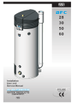
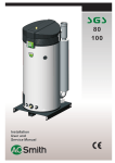
Cyclone BFC
Condensing Glass-Lined
Water Heater
BFC - 28/30/50/60/80/100
Meets
EPC
standards
Fully room-sealed condensing high-efficiency water heater (95%gross)
• Flexible flue options (maximum length 115 m) allows installation
almost anywhere • ThermoControl for easy flexible control/fault
diagnosis • Meets latest EPC standards: Cyclone BFC 28-60: 0.902
• Utilises premix Low-NOx burner BFC 80/100 • Patented Cyclone
burner BFC28-60 • All models suitable for natural or LP gas
• Programmable for legionella purge cycle • Scale formation is
reduced through the improved design and location of the heat
exchanger • Cyclone BFC 80/100: comes as standard with powered
anodes to reduce maintenance requirements • Remote control
connection • Voltage-free contact for general fault indication
• Optional ancillaries: Unvented kits • Destratification pump kit
• Powered anodes
Innovation has a name.
Cyclone BFC
BFC 30
BFC 50
BFC 80
BFC 100
kW
kW
mbar
mbar
m3/h
mm
°C
kg/h
32.1
30.5
20
8.5
3.1
4.90
70
56.8
34.5
32.7
20
8.5
3.3
5.10
50
61.1
52.6
48.8
20
8.5
5.0
7.00
75
85.4
63.2
59.6
20
11.5
6.0
7.10
75
101.4
86.6
81.9
20
7.0
8.3
6.30
50
141.9
105.5
99.8
20
6.0
10.1
6.80
50
164.3
kW
kW
mbar
mbar
kg/h
mm
°C
kg/h
30.7
29.8
30
30
2.2
2.50
70
60.0
32.8
31.8
30
30
2.4
2.60
50
62.2
50.6
48.1
30
30
3.7
3.40
75
86.0
59.4
57.4
30
30
4.3
3.80
75
101.9
-
-
-
-
-
-
-
-
-
kW
kW
mbar
mbar
kg/h
mm
°C
kg/h
29.0
28.1
37
37
2.1
2.50
70
54.3
30.9
29.8
37
37
2.2
2.60
50
56.5
50.3
47.7
37
37
3.6
3.40
75
85.1
59.1
56.9
37
37
4.2
3.80
75
101.0
84.8***
81.9***
37***
13.0***
6.1***
4.70***
50***
142.1***
l
°C
217
80
368
80
368
80
368
80
460
80
460
80
505
802
1100
1398
595
22
444
707
968
1230
524
25
404
642
880
1118
476
27
689
1008
1327
1646
638
35
606
887
1168
1449
562
39
551
806
1062
1317
511
43
831
1308
1785
2262
954
23
731
1151
1571
1991
840
26
665
1046
1418
1810
763
29
925
1507
2089
2671
1164
19
814
1326
1839
2351
1024
22
740
1206
1671
2137
931
24
1222
2023
2823
3623
1601
17
1076
1780
2484
3189
1409
20
978
1618
2258
2899
1281
22
1379
2354
3329
4304
1950
14
1214
2072
2929
3787
1716
16
1109
1883
2663
3443
1560
18
Power consumption
W
275
Power supply
VAC/Hz
275
BFC 60
BFC 28
Technical specifications
Gas data natural gas 2H (G20)
Input*
Output
Inlet pressure
Burner pressure
Gas consumption**
Diameter main orifice
Max. flue gas temperature
Flue gas discharge
Gas data butane 3+ (G30)
Input*
Output
Inlet pressure
Burner pressure
Gas consumption**
Diameter main orifice
Max. flue gas temperature
Flue gas discharge
Input*
Output
Inlet pressure
Burner pressure
Gas consumption**
Diameter main orifice
Max. flue gas temperature
Flue gas discharge
103.3***
99.8***
37***
13.0***
7.4***
5.10***
50***
176.4***
*** 3P (G31)
Gas data propane 3+ (G31)
Draw-off capacity
Storage capacity
Max. temperature setting
Tcold = 10ºC / Tset = 70ºC
30 min. ∆T=44°C
60 min. ∆T=44°C
90 min. ∆T=44°C
120 min. ∆T=44°C
Continuous ∆T=44°C
Heating-up time ∆T=44°C
30 min. ∆T=50°C
60 min. ∆T=50°C
90 min. ∆T=50°C
120 min. ∆T=50°C
Continuous ∆T=50°C
Heating-up time ∆T=50°C
30 min. ∆T=55°C
60 min. ∆T=55°C
90 min. ∆T=55°C
120 min. ∆T=55°C
Continuous ∆T=55°C
Heating-up time ∆T=55°C
l
l
l
l
l/h
min.
l
l
l
l
l/h
min.
l
l
l
l
l/h
min.
Electrical data
General
Fan rotational speed at ignition
r.p.m.
4500
4500
4500
4500
2790
Working speed of fan
r.p.m.
5000
5400
6000
6660
5100
Pressure differential
Pa
635/605
855/825
885/855
1085/1055
1005/975
Diameter of air restrictor
mm
23
23
28
29
36
Anodes
-
4
4
4
4
2
Maximum working pressure
bar
8
3120
5700
1145/1115
38
2
Shipping data
Weight empty
Maximum weight
Weight incl. packaging
Width packaging
Height packaging
Depth packaging
kg
kg
kg
mm
mm
mm
177
394
197
790
1550
950
214
582
234
790
2080
950
214
582
234
790
2080
950
214
582
234
790
2080
950
480
940
491
920
2060
1020
480
940
491
920
2060
1020
* Gas data on gross value
**Gas consumption at 15°C and 1013.25 mbar
275
275
625
710
2
30 (-15/+10%). 50 (+/-1Hz)
Cyclone BFC
Dimensions
BFC 80-100
1390
705
80/125
1365
265
375
1270
170
1390
205
170
85
900
125
1910
705
100/150
1905
265
375
1800
160
1910
205
175
75
1410
145
1910
705
100/150
1905
265
375
1800
160
1910
205
175
75
1410
145
1
2
3
4
5
6
7
Cold water (external)
Hot water (external)
Gas control (internal)
Tank drain valve (internal)
T&P valve (internal)
Cleaning and inspection opening
Condensation drainage (internal)
1910
705
100/150
1905
265
375
1800
160
1910
205
175
75
1410
145
2060
530
850
1000
900
130/200
2015
310
440
1855
225
2060
205
290
225
1425
240
BFC 100
BFC 50
A
C
D
E
F
G
H
Hx
Hy
K
M
N
Ny
P
R
S
W
BFC 80
BFC 30
BFC 60
BFC 28
BFC 28-60
2060
530
850
1000
900
130/200
2015
310
440
1855
225
2060
205
290
225
1425
240
R11/2
R11/2
Rp 3/4
3/4
1-11.5 NPT
95x70
Ø40 (BFC 28)
Rp 1 (BFC 30-100)
Dimensions in mm. All Cyclone BFC water heaters receive a
three years warranty on the tank and one year on parts.
Cyclone BFC
Installation diagrams
Vented
1
3
4
5
6
9
10
11
12
13
14
15
16
17
18
19
Pressure reducing valve
T&P valve
Stop valve
Non-return valve
Circulation pump
Drain valve
Gas cock
Isolating valve
Temperature gauge
Condense drain
Hot water outlets
Expansion relief valve
Expansion vessel
Three way valve
Water tank
Float valve
A
B
C
Cold water
Hot water
Return circulation
D
E
H
Gas supply
Overflow pipe
Expansion vent pipe
A.O. Smith unvented system kits utilise combination valves.
Further installation and connection details can be found in
the Installation & Commissioning Manual.
Unvented
Cyclone BFC
Electrical diagram BFC 28-60
TERMINAL STRIP CONNECTIONS
Earth
N Neutral
L1 Phase input of controller
L2 Phase input of isolating
transformer (primary side)
L3 Phase output of isolating
transformer (secondary side)
L4 Phase input of program-controlled
pump
L5 Phase input of continuous pump
COMPONENTS
A Controller
B Ionisation rod
C Glow igniter
D Gas control
E Burner earth connection
F Extra ON mode switch
G Continuous pump
H Program-controlled pump
J Extra error signal
K Isolating transformer
L Double-pole mains switch
M ON/OFF switch control
N Display/Flat cable
O Fan
P Temperature sensor
(T2 - bottom of tank)
Q Dummy
R Temperature sensor
(T1 - top of tank)
S Selection resistor
T Pressure switch
CONTROLLER CONNECTIONS
J1 Connector for display to controller
J2 Connector for power supply to
controller
J19 Connector for extra error signal
J20 Connector for gas control
J21 Connector for program
controlled pump
J24 Connector for fan
JP2 Connector for ionisation rod and
glow igniter
JP3 Connector for temperature
sensor T2
JP4 Connector for dummy
JP5 Connector for temperature
sensor T1
JP6 Connector for selection resistor
and pressure switch
JP8 Connector for extra
ON mode switch
F1 Fuse
F2 Fuse
Colour cables
1 = brown
2 = blue
3 = yellow/green
4 = black
5 = white (flat cable)
6 = grey/beige
Cyclone BFC
Electrical diagram BFC 80-100
TERMINAL STRIP CONNECTIONS
Earth
N Neutral
L
Phase input of controller
L1 Phase output of isolating
transformer ( secundary side)
L2 Phase input of isolating
transformer ( primary side)
L3 Phase input of program
controlled pump
L4 Phase input of frequency
controller
L5 Phase input of continuous pump
COMPONENTS
A Controller
B Ionisation rod
C Glow ignitor
D Gas control
E
Burner earth connection
F
External ON-mode switch
G Program-controlled pump
H External error-signal
J
Isolating transformer
K Double-pole mains switch
L
Controller 0/1 switch
M Display/Flat cable
N Fan
O Temperaturesensor
(T2-bottom of tank)
P
Dummy
Q Temperaturesensor
(T1-top of tank)
R Selection resistor
S
Pressure switch
T
Potentiostat
U Frequency controller
V Argus-link interface
W Electric anodes
X Signaling for electric anodes
Y Mains choke and EMC filter
CONTROLLER CONNECTIONS
J2 Connector for power supply
to controller
J19 Connector for external error-signal
J20 Connector for gas-control
J21 Connector for program
controlled pump
J36 Connector for display
to controller
J39 Connector for fan controlled signal
JP2 Connector for ionisation rod and
glow ignitor
JP3 Connector for temperature
sensor T2
JP4 Connector for dummy
JP5 Connector for temperature
sensor T1
JP6 Connector for selection resistor,
pressure switch and anode
signaling
JP8 Connector for extra
ON-mode switch
F1
F3
Fuse
Fuse
Colour cables
1 = brown
2 = blue
3 = yellow/green
4 = black
5 = white (flat cable)
6 = grey/beige
7 = red
8 = green
Flue systems Cyclone BFC
Installation options
BFC 100
BFC 80
BFC 60
BFC 50
BFC 28
C13
BFC 30
A Cyclone BFC water heater should be installed according
category B23, C13, C33, C43 or C53*.
Concentric
B23
Diameter (mm)
80/125
100/150 100/150 100/150 130/200 130/200
Max. length (m)
40 40 40 15 15 15
Max. 45/90° bends
7
7
7
4
3
3
Parallel (standard diameter)
Diameter (mm)
80
100
100
100
130
130
Max. length (m)
25 80 45 25 115 60
Lequivalent/bend 90° (m) 3,9 4,6 4,6 4,6 2,4 2,4
Lequivalent/bend 45º (m) 1,1 1,2 1,2 1,2 1,4 1,4
Parallel (larger diameter for more length)
C33
Diameter (mm)
100
130
130
130
150
150
Max. length (m)
100
100
100
100
100
100
Lequivalent/bend 90º (m) 4,6 2,4 2,4 2,4 2,6 2,6
Lequivalent/bend 45º (m) 1,2 1,4 1,4 1,4 1,6 1,6
* All Cyclone BFC are also approved for installations where the unit is supplied
without venting materials (C63).
Concentric flues
It is not permitted to use more than the specified number of
bends, even when the duct is shorter than the maximum
length. A 45° bend is equivalent to a 90° bend.
Parallel flues
- The maximum permissible length should be reduced by the
equivalent length of each bend. (Note: for a parallel installation
this means that 3 changes in direction amount to 6 bends
(3 in the supply duct and 3 in the flue).
- The maximum length also applies if a parallel installation has
different supply and flue duct lengths (B23, C53).
- Combined flues (C43) shall be fitted with a condensate drain.
C53
C43
Note: horizontal flue runs must be installed with a fall of at least
5 mm per metre.
BFC 100
BFC 80
BFC 60
BFC 50
BFC 28-60
BFC 28
Minimum space requirements
BFC 30
Flue systems Cyclone BFC
550
550
550
550
640
640
725
790
790
790
940
940
X
1535
2075
2075
2075
2230
2230
Y
1460
1480
1480
1480
1620
1620
Y *
1010
1030
1030
1030
1170
1170
Minimal space for roof duct (mm)
BFC 80-100
V
1305
1500
1500
1500
1730
1730
W
680
1035
1035
1035
1120
1120
X
2965
3325
3325
3325
3620
3620
X **
2015
2375
2375
2375
2670
2670
Y
1575
1415
1415
1415
1560
1560
Y **
625
465
465
465
610
610
For the parts numbers of components and flue gas ducts, etc.
please refer to the “Maintenance and accessories” chapter.
* Distance without concentric pipe between bend and wall duct.
** Distance without concentric pipe between appliance and roof duct.
www.aosmithinternational.com
Data subject to change INT/1108/BFC/04
V
W
Terms and conditions apply, please refer to our website
Ø80/125 Ø100/150 Ø100/150 Ø100/150 Ø130/200 Ø130/200
Minimal space for wall duct (mm)