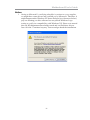
1
Motherboard User’s Guide This publication, including photographs, illustrations and software, is under the protection of international copyright laws, with all rights reserved. Neither this user’s guide, nor any of the material contained herein, may be reproduced without the express written consent of the manufacturer. The information in this document is subject to change without notice. The manufacturer makes no representations or warranties with respect to the contents hereof and specifically disclaims any implied warranties of merchantability or fitness for any particular purpose. Further, the manufacturer reserves the right to revise this publication and to make changes from time to time in the content hereof without obligation of the manufacturer to notify any person of such revision or changes. Trademarks IBM, VGA, and PS/2 are registered trademarks of International Business Machines. MMX, Pentium, Pentium-II, Pentium-III, Celeron are registered trademarks of Intel Corporation. Microsoft, MS-DOS and Windows XP/Vista/7 are registered trademarks of Microsoft Corporation. AMI is a trademark of American Megatrends Inc. It has been acknowledged that other brands or product names in this manual are trademarks or the properties of their respective owners. Static Electricity Precautions 1. Don’t take this motherboard and components out of their original staticproof package until you are ready to install them. 2. While installing, please wear a grounded wrist strap if possible. If you don’t have a wrist strap, discharge static electricity by touching the bare metal of the system chassis. 3. Carefully hold this motherboard by its edges. Do not touch those components unless it is absolutely necessary. Put this motherboard on the top of static-protection package with component side facing up while installing. Pre-Installation Inspection 1. Inspect this motherboard whether there are any damages to components and connectors on the board. 2. If you suspect this motherboard has been damaged, do not connect power to the system. Contact your motherboard vendor about those damages. Copyright © 2011 All Rights Reserved P65G Series, V1.0 October 2011 i Motherboard User’s Guide Table of Contents Trademark ............................................................................................................ i Static Electricity Precautions ......................................................................................... i Pre-Installation Inspection ............................................................................................. i Chapter 1: Introduction ..................................................................................... 1 Key Features .................................................................................................................... 1 Package Contents ........................................................................................................... 4 Chapter 2: Motherboard Installation .............................................................. 5 Motherboard Components ............................................................................................ 6 I/O Ports .......................................................................................................................... 7 Installing the Processor ................................................................................................. 8 Installing Memory Modules ........................................................................................ 1 0 Jumper Settings ............................................................................................................ 1 2 Install the Motherboard ............................................................................................... 1 4 Connecting Optional Devices ..................................................................................... 1 5 Install Other Devices .................................................................................................... 1 8 Expansion Slots ............................................................................................................ 1 9 Chapter 3: BIOS Setup Utility ....................................................................... 21 Introduction .................................................................................................................. 2 1 Running the Setup Utility ............................................................................................ 2 1 Main Setup Page .......................................................................................................... 2 4 Advanced Setup Page .................................................................................................. 2 5 Chipset Setup Page ...................................................................................................... 3 4 Tweak Setup Page ......................................................................................................... 4 1 Boot Setup Page ........................................................................................................... 4 7 Securtiy Setup Page ..................................................................................................... 4 9 Exit Setup Page ............................................................................................................ 5 0 Chapter 4: Software & Applications .............................................................. 52 Introduction .................................................................................................................. 5 2 Installing Support Software ........................................................................................ 5 2 Bundled Software Installation .................................................................................... 5 4 Chapter 5: Trouble Shooting ........................................................................... 55 Start up problems during assembly.....................................................................55 Start up problems after prolong use....................................................................56 Maintenance and care tips...................................................................................56 Basic Troubleshooting Flowchart.........................................................................57 ii Motherboard User’s Guide Notice: 1 Owing to Microsoft’s certifying schedule is various to every supplier, we might have some drivers not certified yet by Microsoft. Therefore, it might happen under Windows XP that a dialogue box (shown as below) pop out warning you this software has not passed Windows Logo testing to verify its compatibility with Windows XP. Please rest assured that our RD department has already tested and verified these drivers. Just click the “Continue Anyway” button and go ahead the installation. iii Motherboard User’s Guide Chapter 1 Introduction This motherboard has a LGA1155 socket for latest 2nd Generation Intel® CoreTM i7/i5/i3 series processor/Intel® Pentium® /Celeron® processors for high-end business or personal desktop markets. This motherboard is based on Intel® H61 Express Chipset for best desktop platform solution. H61 is a single-chip, highly integrated, high performance HyperThreading peripheral controller, unmatched by any other single chip device controller. This motherboard supports up to 16 GB of system memory with dual channel DDR3 1333/1066 SDRAM. High resolution graphics via PCI Express x16 slot, intended for Graphics Interface, is fully compliant to the PCI Express Base Specification revision 2.0. In addition, two PCI Express slots are supported. It implements an EHCI (Enhanced Host Controller Interface) compliant interface that provides eight USB 2.0 ports (four USB 2.0 ports at the back panel and two USB 2.0 headers support additional four USB 2.0 ports). The motherboard is equipped with advanced full set of I/O ports in the rear panel, including PS/2 mouse and PS/2 keyboard connectors, one D_sub (VGA) port, one Lan port, four USB 2.0 ports, and audio jacks for microphone, line-in and 6-ch lineout. In addition, this motherboard supports four SATA 3.0 Gb/s connectors for expansion. Key Features The key features of this motherboard include: LGA 1155 Socket Processor • Accommodates latest 2nd Generation Intel® CoreTM Family processor/ Intel® Pentium®/Celeron® processors • Supports “Hyper-Threading” technology CPU • One PCI Express x16 Gen2 port supporting up to 5 GB/s direction peak bandwidth “Hyper-Threading” technology enables the operating system into thinking it’s hooked up to two processors, allowing two threads to be run in parallel, both on separate “logical” processors within the same physical processor. 1 Motherboard User’s Guide Chipset The Intel® H61 Chipset is a single-chip with proven reliability and performance. • High performance Host Interface: Supports the LGA1155 socket for latest 2nd Generation Intel® CoreTM Family processor/Intel® Pentium® / Celeron® processors • System Memory Controller Support: DDR3 SDRAM with up to maximum memory of 16 GB • Support two PCI Express x1 slots • Integrate Serial ATA Host Controller with Data transfer rates up to 3.0 Gb/s • Serial Peripheral Interface (SPI) support • Integrated Graphics Support with PAVP 1.5 • Intel® High Definition Audio Controller • USB 2.0: Integrated USB 2.0 interface, supporting up to eight functional ports Memory Support • Two 240-pin DIMM sockets for DDR3 1333/1066 SDRAM with Dualchannel architecture • Maximum installed memory is 16 GB Expansion Slots • One PCI Express x16 slot • Two PCI Express x 1 slots Serial ATA • Serial ATA Controller • Transfer rate exceedig best ATA (3.0 Gb/s) with scalability to higher rates • Low pin count for both host and devices Audio • • • • • • 5.1+2 Channel High Definition Audio Codec Meets Microsoft WLP3.x (Windows Logo Program) audio requirements All DACs supports 44.1k/48k/96k/192kHz sample rate Software selectable 2.5V/3.2V/4.0V VREFOUT Direct Sound 3D compatible Power Support: Digital: 3.3V; Analog: 5.0V 2 Chapter 1: Introduction Onboard LAN (Optional) • • • • • • Supports PCI ExpressTM 1.1 Integrated 10/100/1000 transceiver Wake-on-LAN and remote wake-up support Supports PCI ExpressTM 1.1 Integrated 10/100 transceiver Wake-on-LAN and remote wake-up support Onboard I/O Ports • Two PS/2 ports for mouse and keyboard • One VGA port • One LAN port • Four USB 2.0 ports • Audio jacks for microphone, line-in and 6-ch line-out BIOS Firmware The motherboard uses AMI BIOS that enables users to configure many system features including the following: • Power management • Wake-up alarms • CPU parameters • CPU and memory timing • Graphic parameters The firmware can also be used to set parameters for different processor clock speeds. Dimensions • Micro ATX form factor of 225x170 mm Note: Hardware specifications and software items are subject to change without notification. 3 Motherboard User’s Guide Package Contents Your motherboard package ships with the following items: The motherboard The User’s Guide Two Serial ATA cables The Software support disk Optional Accessories You can purchase the following optional accessories for this motherboard. The Extended USB module The Serial ATA power cable Note: You can purchase your own optional accessories from the third party, but please contact your local vendor on any issues of the specification and compatibility. 4 Chapter 2: Motherboard Installation Chapter 2 Motherboard Installation To install this motherboard in a system, please follow these instructions in this chapter: Identify the motherboard components Install a CPU Install one or more system memory modules Make sure all jumpers and switches are set correctly Install this motherboard in a system chassis (case) Connect any extension brackets or cables to headers/connectors on the motherboard Install peripheral devices and make the appropriate connections to headers/connectors on the motherboard Note: 1. 2. Before installing this motherboard, make sure jumper CLR_CMOS is under Normal setting. See this chapter for information about locating CLR_CMOS and the setting options. Never connect power to the system during installation; otherwise, it may damage the motherboard. 5 Motherboard User’s Guide Motherboard Components LABEL 1. CPU Socket 2. CPU_FAN 3. DDR3_1~2 4. ATX_POWER 5. SPI_DEBUG 6. SATA1~4 7. F_PANEL 8. F_USB1~2 9. CASE 10. USBPWR_F1 11. SPK 12. LDC 13. COM 14. ME_UNLOCK 15. SYS_FAN 16. F_AUDIO 17. CLR_CMOS 18. PCIE1~2 19. PCIEX16 20. USBPWR_R1 21. ATX12V COMPONENTS nd ® TM LGA1155 socket for new 2 Generation Intel Core i7/i5/i3 ® ® ® series processor/Intel Pentium /Celeron processors 4-pin CPU cooling fan connector 240-pin DDR3 SDRAM slots Standard 24-pin ATX power connector SPI debug header-for factory use only Serial ATA 3.0 Gb/s connectors Front panel switch/LED header Front panel USB 2.0 headers CASE open header Front Panel USB power select jumper Speaker header Debug card header Onboard serial port header ME unlock header-for factory use only 3-pin system cooling fan connector Front panel audio header Clear CMOS jumper PCI Express x1 slot PCI Express slot for graphics interface Rear USB/PS2 power select jumper 4-pin +12V power connector 6 Chapter 2: Motherboard Installation I/O Ports The illustration below shows a side view of the built-in I/O ports on the motherboard. PS/2 Mous e Use the upper PS/2 port to connect a PS/2 pointing device. PS/2 Key boar d Use the lower PS/2 port to connect a PS/2 keyboard. VG A Por t Connect your monitor to the VGA port. LAN Por t Connect an RJ-45 jack to the LAN port to connect your computer to the Network. USB 2.0 Por ts Use the USB 2.0 ports to connect USB 2.0 devices. Audio Por ts Use the three audio jacks to connect audio devices. The first jack is for stereo Line-In signal, the second jack is for stereo Line-Out signal, and the third jack for Microphone. 7 Motherboard User’s Guide Installing the Processor This motherboard has a LGA1155 socket for latest 2nd Generation Intel® Core TM Family processors. When choosing a processor, consider the performance requirements of the system. Performance is based on the processor design, the clock speed and system bus frequency of the processor, and the quantity of internal cache memory and external cache memory. CPU Installation Procedure Follow these instructions to install the CPU: A. Disengaging of the Load Lever · Press the hook of lever down and pull it to the right side to release it from retention tab. B. Opening of the Load Plate · Lift the tail of the load lever. · Rotate the load plate to fully open position. C. Removing the Cap · Be careful not to touch the contact at any time. 8 Chapter 2: Motherboard Installation D. Inserting the Package · Grasp the package. Ensure to grasp on the edge of the substrate. · Make sure pin 1 indicator is on your bottom-left side. · Aim at the socket and place the package carefully into the socket by purely vertical motion. E. Closing the Load Plate · Rotate the load plate onto the package IHS (Intergraded Heat Spreader). · Engage the load lever while pressing down lightly onto the load plate. · Secure the load lever with the hook under retention tab. F. Fasten the cooling fan supporting base onto the CPU socket on the motherboard. G. Make sure the CPU fan is plugged to the CPU fan connector. Please refer to the CPU cooling fan user’s manual for more detail installation procedure. * For reference only Note 1: To achieve better airflow rates and heat dissipation, we suggest that you use a high quality fan with 3800 rpm at least. CPU fan and heatsink installation procedures may vary with the type of CPU fan/ heatsink supplied. The form and size of fan/heatsink may also vary. Note 2: The fan connector supports the CPU cooling fan of 1.1A~2.2A (26.4W max.) at +12V. Note 3: Do Not remove the CPU cap from the socket before installing a CPU. Note 4: Return Material Authorization (RMA) requests will be accepted only if the motherboard comes with the cap on the LGA1155 socket. 9 Motherboard User’s Guide Installing Memory Modules This motherboard accommodates two 240-pin DIMM sockets for unbuffered DDR3 1333/1066 memory modules, and maximum 16 GB installed memory. 10 Chapter 2: Motherboard Installation Memory Module Installation Procedure These modules can be installed with up to 16 GB system memory. Refer to the following to install the memory module. 1. Push down the latches on both sides of the DIMM socket. 2. Align the memory module with the socket. There is a notch on the DIMM socket that you can install the DIMM module in the correct direction. Match the cutout on the DIMM module with the notch on the DIMM socket. 3. Install the DIMM module into the socket and press it firmly down until it is seated correctly. The socket latches are levered upwards and latch on to the edges of the DIMM. 4. Install any remaining DIMM modules. * For reference only 11 Motherboard User’s Guide Jumper Settings Connecting two pins with a jumper cap is SHORT; removing a jumper cap from these pins, OPEN. CLR_CMOS: Clear CMOS Jumper Use this jumper to clear the contents of the CMOS memory. You may need to clear the CMOS memory if the settings in the Setup Utility are incorrect and prevent your motherboard from operating. To clear the CMOS memory, disconnect all the power cables from the motherboard and then move the jumper cap into the CLEAR setting for a few seconds. 1 CLR_CMOS Function Jum per Setting Normal Short Pins 1-2 Clear CMOS Short Pins 2-3 Note: To avoid the system unstability after clearing CMOS, we recommend users to enter the main BIOS setting page to “Load Optimal Defaults” and then “Save Changes and Exit”. 12 Chapter 2: Motherboard Installation USBPWR_F1: FRONT PANEL USB POWER SELECT Jumper 1 USBPWR_F1 Function VCC 5VSB Jum per Setting Short Pins 1-2 Short Pins 2-3 USBPWR_R1: REAR USB PS/2 POWER SELECT Jumper Use this jumper to set the Rear USB PS/2 Power function. 1 USBPWR_R1 Function VCC 5VSB Jum per Setting Short Pins 1-2 Short Pins 2-3 Note:1. Make sure the power supply provides enough SB5V voltage before selecting the SB5V function. 2. To wake up the computer by USB/PS2 KB/Mouse in S3 status, users have to place the USBPWR_F & USBPWR_R cap onto 2-3 pin instead of 12 as default, and then press into BIOS “Power Management Setup”page to choose the functions (USB/PS2KB/MS) you want to enable. 13 Motherboard User’s Guide Install the Motherboard Install the motherboard in a system chassis (case). The board is a Micro ATX size motherboard. You can install this motherboard in an ATX case. Make sure your case has an I/O cover plate matching the ports on this motherboard. Install the motherboard in a case. Follow the case manufacturer’s instructions to use the hardware and internal mounting points on the chassis. Connect the power connector from the power supply to the ATX_POWER connector on the motherboard. The ATX12V is a +12V connector for CPU Vcore power. If there is a cooling fan installed in the system chassis, connect the cable from the cooling fan to the CPU_FAN fan power connector on the motherboard. Connect the case switches and indicator LEDs to the F_PANEL header. Here is a list of the F_PANEL pin assignments. Pin 1 3 5 7 9 Signal HD_LED_P(+) HD_LED_N(-) RESET_SW_N(-) RESET_SW_P(+) RSVD_DNU Pin 2 4 6 8 10 14 Signal FP PWR/SLP(+) FP PWR/SLP(-) POWER_SW_P(+) POWER_SW_N(-) KEY Chapter 2: Motherboard Installation Connecting Optional Devices Refer to the following for information on connecting the motherboard’s optional devices: SPK: Speaker Header Connect the cable from the PC speaker to the SPK header on the motherboard. Pin 1 3 Signal VCC NC Pin 2 4 Signal Key Signal LDC: Debug Card header This is a header that can be used to support the LPC debug card. Pin Signal 1 LAD3 3 5 Pin Signal 2 +3.3V LAD2 4 LFRAME# LAD1 6 RST 7 LAD0 8 CLK 9 GND 10 KEY 15 Motherboard User’s Guide COM: Onboard Serial Port Header Connect a serial port extension bracket to this header to add a second serial port to your system. Pin 1 3 5 7 9 Signal DCDB SOUTB GND RTSB RI Pin 2 4 6 8 10 Signal SINB DTRB DSRB CTSB KEY F_AUDIO: Front Panel Audio Header This header allows the user to install auxiliary front-oriented microphone and lineout ports for easier access. Pin 1 3 5 7 9 Signal PORT1L PORT1R PORT2R SENSE_SEND PORT2L Pin Signal 2 GND 4 PRESENCE# 6 Sense1_return 8 KEY 10 Sense2_return F_USB1~2: Front Panel USB Headers The motherboard has four USB ports installed on the rear edge I/O port array. Additionally, some computer cases have USB ports at the front of the case. If you have this kind of case, use auxiliary USB header F_USB to connect the frontmounted ports to the motherboard. Pin 1 3 5 7 9 1. 2. 3. Signal USBPWR0 USB_FP_P0(-) USB_FP_P0(+) GROUND KEY Pin 2 4 6 8 10 Signal USBPWR1 USB_FP_P1(-) USB_FP_P1(+) GROUND NC Locate the F_USB header on the motherboard. Plug the bracket cable onto the F_USB header. Remove a slot cover from one of the expansion slots on the system chassis. Install an extension bracket in the opening. Secure the extension bracket to the chassis with a screw. 16 Chapter 2: Motherboard Installation CASE: Chassis Intrusion Detect Header This detects if the chassis cover has been removed. This function needs a chassis equipped with instrusion detection switch and needs to be enabled in BIOS. Pin Function Short Chassis cover is removed Open Chassis cover is closed ME_UNLOCK: ME Unlock Header Pin Function Short Unlock Open Lock 17 Motherboard User’s Guide Install Other Devices Install and connect any other devices in the system following the steps below. Serial ATA Devices The Serial ATA (Advanced Technology Attachment) is the standard interface for the IDE hard drives, which is designed to overcome the design limitations while enabling the storage interface to scale with the growing media rate demands of PC platforms. It provides you a faster transfer rate of 3.0 Gb/s. If you have installed a Serial ATA hard drive, you can connect the Serial ATA cables to the Serial ATA hard drive or the connector on the motherboard. On the motherboard, locate the Serial ATA connectors SATA1~4, which support new Serial ATA devices for the highest data transfer rates, simpler disk drive cabling and easier PC assembly. 18 Chapter 2: Motherboard Installation Expansion Slots This motherboard has one PCI Express x16, two PCI Express x1 slots. Follow the steps below to install a PCI Express expansion card. 1 Locate the PCI Express slot on the motherboard. 2 Remove the blanking plate of the slot from the system chassis. 3 Install the edge connector of the expansion card into the slot. Ensure the edge connector is correctly seated in the slot. 4 Secure the metal bracket of the card to the system chassis with a screw. * For reference only 19 Motherboard User’s Guide PCI Express x16 Slot You can install an external PCI Express graphics card that is fully compliant to the PCI Express Base Specification revision 2.0. PCI Express Slots You can install two external PCI Express graphics cards that are fully compliant to the PCI Express Base Specification revision 2.0. 20 Chapter 3: BIOS Setup Utility Chapter 3 BIOS Setup Utility Introduction The BIOS Setup Utility records settings and information of your computer, such as date and time, the type of hardware installed, and various configuration settings. Your computer applies the information to initialize all the components when booting up and basic functions of coordination between system components. If the Setup Utility configuration is incorrect, it may cause the system to malfunction. It can even stop your computer booting properly. If it happens, you can use the clear CMOS jumper to clear the CMOS memory which has stored the configuration information; or you can hold down the Page Up key while rebooting your computer. Holding down the Page Up key also clears the setup information. You can run the setup utility and manually change the configuration. You might need to do this to configure some hardware installed in or connected to the motherboard, such as the CPU, system memory, disk drives, etc. Running the Setup Utility Every time you start your computer, a message appears on the screen before the operating system loading that prompts you to “Hit <DEL>if you want to run SETUP” . Whenever you see this message, press the Delete key, and the Main menu page of the Setup Utility appears on your monitor. Version 2.02.1205. Copyright (C) 2010, American Megatrends, Version 2.02.1205. Copyright (C) 2010, American Megatrends, Inc. Inc. You can use cursor arrow keys to highlight anyone of options on the main menu page. Press Enter to select the highlighted option. Press the Escape key to leave the setup utility. Press +/-/ to modify the selected field’s values. 21 Motherboard User’s Guide Some options on the main menu page lead to tables of items with installed values that you can use cursor arrow keys to highlight one item, and press PgUp and PgDn keys to cycle through alternative values of that item. The other options on the main menu page lead to dialog boxes requiring your answer OK or Cancel by selecting the [OK] or [Cancel] key. If you have already changed the setup utility, press F4 to save those changes and exit the utility. Press F1 to display a screen describing all key functions. Press F3 to load optimal settings. Language Select the language icon and press <Enter> or double click the left key of the mouse to display the following screen. Then you can choose the language which displays in the following screen. Default Select the default icon and press <Enter> or double click the left key of the mouse to display the following screen. Then you can load optimized defaults or not. 22 Chapter 3: BIOS Setup Utility Boot Select the boot icon and press <Enter> or double click the left key of the mouse to display the following screen. Then you can choose the boot device. Advanced Select the advanced icon and press <Enter> or double click the left key of the mouse to display the following screen. 23 Motherboard User’s Guide Main Setup Page This page displays a table of items defining basic information of your system. Main Advanced Chipset Tweak BIOS Information System Language System Date System Time English Boot Security Exit Choose the system default language Tue 07/21/2011 21:54:19 lk : Select Screen mn /Click: Select Item Enter/Dbl Click : Select +/- : Change Opt. F1: General Help F2: Previous Values F3: Optimized Defaults F4: Save & Exit ESC/Right Click: Exit Multi-Language BIOS Multi-language BIOS allows you to see and set up the BIOS with your native language. It helps Non-English users to solve the problem of setting up the BIOS and achieve extra system performance easily. Date & Time The Date and Time items show the current date and time on the computer. If you are running a Windows OS, these items are automatically updated whenever you make changes to the Windows Date and Time Properties utility. 24 Chapter 3: BIOS Setup Utility Advanced Setup Page This page sets up more advanced information about your system. Handle this page with caution. Any changes can affect the operation of your computer. Main Advanced Chipset Legacy OpROM Support Launch PXE OpROM Launch Storage OpROM Tweak Boot Security Exit Enabled/Disabled Onboard LAN Option ROM Disabled Enabled LAN Configuration PC Health Status Power Management Setup ACPI Settings CPU Configuration SATA Configuration USB Configuration Super IO Configuration lk : Select Screen mn /Click: Select Item Enter/Dbl Click : Select +/- : Change Opt. F1: General Help F2: Previous Values F3: Optimized Defaults F4: Save & Exit ESC/Right Click: Exit Launch PXE OpROM (Disabled) Use this item to enable or disable the PXE OpROM. Launch Storage OpROM (Enabled) Use this item to enable or disable the Storage OpROM. LAN Configuration The item in the menu shows the LAN-related information that the BIOS automatically detects. Main Advanced Chipset Tweak LAN Configuration Onboard LAN Controller Enabled Boot Security Exit Enabled/Disabled Onboard LAN Controller lk : Select Screen mn /Click: Select Item Enter/Dbl Click : Select +/- : Change Opt. F1: General Help F2: Previous Values F3: Optimized Defaults F4: Save & Exit ESC/Right Click: Exit 25 Motherboard User’s Guide Onboard LAN Controller (Enabled) Use this item to enable or disable the Onboard LAN. Press <Esc> to return to the Advanced Menu page. PC Health Status On motherboards support hardware monitoring, this item lets you monitor the parameters for critical voltages, temperatures and fan speeds. Main Advanced Chipset Tweak Boot PC Health Status Security Exit Smart Fan Function Smart Fan Function CPU Fan Speed CPU Voltage AXG Voltage DIMM Voltage : : : : 1702 RPM 1.176V 1.048 V 1.520 V -=- PECI Mode -=Offset to TCC Activation Temp. : lk : Select Screen mn /Click: Select Item Enter/Dbl Click : Select +/- : Change Opt. F1: General Help F2: Previous Values F3: Optimized Defaults F4: Save & Exit ESC/Right Click: Exit -35 fSmart Fan Function Scroll to this item and press <Enter> to view the following screen: Main Advanced Chipset CPU Smart Fan Control Smart Fan Mode High Limit Offset (-) Low Limit Offset (-) High Limit PWM Low Limit PWM Tweak Enabled Normal 30 40 200 58 Boot Security Exit CPU Smart Fan Control lk : Select Screen mn /Click: Select Item Enter/Dbl Click : Select +/- : Change Opt. F1: General Help F2: Previous Values F3: Optimized Defaults F4: Save & Exit ESC/Right Click: Exit CPU SMART FAN Control (Enabled) This item allows you to enable/disable the control of the CPU fan speed by changing the fan voltage. 26 Chapter 3: BIOS Setup Utility SMART Fan Mode (Normal) This item allows you to select the fan mode (Normal, Quiet, Silent, or Manual) for a better operation environment. If you choose Normal mode, the fan speed will be auto adjusted depending on the CPU temperature. If you choose Quite mode, the fan speed will be auto minimized for quiet environment. If you choose Silent mode, the fan speed will be auto restricted to make system more quietly. If you choose Manual mode, the fan speed will be adjust depending on users’ parameters. Press <Esc> to return to the PC Health Status page. System Component Characteristics These items display the monitoring of the overall inboard hardware health events, such as System & CPU temperature, CPU & DIMM voltage, CPU & system fan speed,... etc. • • • • CPU Fan Speed CPU Voltage AXG Voltage DIMM Voltage Press <Esc> to return to the Advanced Setup page. 27 Motherboard User’s Guide Power Management Setup This page sets up some parameters for system power management operation. Main Advanced Chipset Tweak Boot Power Management Setup Resume By Ring Resume By PME Resume By USB2.0 (S3) Resume By PS2 KB (S3) Resume By PS2 MS (S3) EUP Function Power LED Type Security Exit About Resume by Ring Disabled Disabled Disabled Disabled Disabled Enabled Dual Color LED lk : Select Screen mn /Click: Select Item Enter/Dbl Click : Select +/- : Change Opt. F1: General Help F2: Previous Values F3: Optimized Defaults F4: Save & Exit ESC/Right Click: Exit Resume By RING (Disabled) The system can be turned off with a software command. If you enable this item, the system can automatically resume if there is an incoming call on the Modem. You must use an ATX power supply in order to use this feature. Resume By PME (Disabled) The system can be turned off with a software command. If you enable this item, the system can automatically resume if there is an incoming call on the PCI Modem or PCI LAN card. You must use an ATX power supply in order to use this feature. Use this item to do wake-up action if inserting the PCI card. Resume By USB2.0 (S3) (Disabled) This item allows you to enable/disable the USB device wakeup function from S3 mode. Resume By PS2 KB (S3) (Disabled) This item enables or disables you to allow keyboard activity to awaken the system from power saving mode. Resume By PS2 MS (S3) (Disabled) This item enables or disables you to allow mouse activity to awaken the system from power saving mode. EUP Support (Enabled) This item allows user to enable or disable EUP support. Power LED Type (Dual Color LED) This item shows the type of the power LED. Press <Esc> to return to the Advanced Setup page. 28 Chapter 3: BIOS Setup Utility ACPI Setting The item in the menu shows the highest ACPI sleep state when the system enters suspend. Aptio Setup Utility - Copyright (C) 2011 American Megatrends, Inc. Main Advanced Chipset Tweak Boot ACPI Settings ACPI Sleep State Security Exit Select the highest ACPI sleep state the system will enter when the Suspend button is pressed. S3 (Suspend to RAM) lk : Select Screen mn /Click: Select Item Enter/Dbl Click : Select +/- : Change Opt. F1: General Help F2: Previous Values F3: Optimized Defaults F4: Save & Exit ESC/Right Click: Exit ACPI Sleep State (S3(Suspend to RAM)) This item allows user to enter the ACPI S3 (Suspend to RAM) Sleep State(default). Press <Esc> to return to the Advanced Setup page. CPU Configuration Scroll to this item and press <Enter> to view the following screen: Main Advanced Chipset Tweak CPU Configuration Security Exit Disabled for Windows XP Intel(R) Core(TM) i5-2400 CPU @ 3.10GHz EMT64 Supported Processor Speed 3100 MHz Processor Stepping 206a6 Microcode Revision 28 Processor Cores 4 Intel HT Technology Not Supported Limit CPUID Maximum Execute Disable Bit Intel Virtualization Technology Power Technology Enhanced Halt (C1E) Boot Disabled Enabled Enabled Energy Efficient Enabled 29 lk : Select Screen mn /Click: Select Item Enter/Dbl Click : Select +/- : Change Opt. F1: General Help F2: Previous Values F3: Optimized Defaults F4: Save & Exit ESC/Right Click: Exit Motherboard User’s Guide Intel(R) Core(TM) i5-2400 CPU 0 @ 3.10GHz This is display-only field and displays the information of the CPU installed in your computer. EMT64 (Supported) This item shows the computer supports EMT64. Processor Speed (3100MHz) This item shows the current processor speed. Processor Stepping (206a6) This item shows the processor stepping version. Microcode Revision (28) This item shows the Microcode version. Processor Cores (4) This item shows the core number of the processor. Intel HT Technology (Not Supported) This item shows that your computer supports Intel HT technology or not. Limit CPUID Maximum (Disabled) Use this item to enable or disable the maximum CPUID value limit. Execute Disable Bit (Enabled) This item allows the processor to classify areas in memory by where application code can execute and where it cannot. When a malicious worm attempts to insert code in the buffer, the processor disables code execution, preventing damage or worm propagation. Replacing older computers with Execute Disable Bit enabled systems can halt worm attacks, reducing the need for virus related repair. Intel Virtualization Technology (Disabled) When disabled, a VMM cannot utilize the additional hardware capabilities provided by Vandor Pool Technology. Enhanced Halt(C1E) (Enabled) This item enables or disables enhanced halt. Press <Esc> to return to the Advanced Setup page. 30 Chapter 3: BIOS Setup Utility SATA Configuration Use this item to show the mode of serial-ATA configuration options. Main Advanced Chipset Tweak Boot SATA Configuration SATA Mode Serial-ATA Controller 0 Serial-ATA Controller 1 Not Present SATA Port2 Not Present SATA Port3 Not Present SATA Port4 Not Present Exit (1) IDE Mode. (2) AHCI Mode. IDE Mode Compatible Enhanced SATA Port1 Security lk : Select Screen mn /Click: Select Item Enter/Dbl Click : Select +/- : Change Opt. F1: General Help F2: Previous Values F3: Optimized Defaults F4: Save & Exit ESC/Right Click: Exit SATA Mode (IDE Mode) Use this item to select SATA mode. Serial-ATA Controller 0/1 (Compatible/Enhanced) Use this item to select the Serial-ATA controller options: Disabled, Compatible, Enhanced. SATA Port 1~4 (Not Present) This motherboard supports four SATA channel and each channel allows one SATA device to be installed. Use these items to configure each device on the SATA channel. Main Advanced Chipset Tweak Boot SATA Configuration SATA Mode Aggressive Link Power Management AHCI Mode Enabled SATA Port1 Staggered Spin-up External SATA Port Not Present Disabled Disabled SATA Port2 Staggered Spin-up External SATA Port Not Present Disabled Disabled SATA Port3 Staggered Spin-up External SATA Port Not Present Disabled Disabled SATA Port4 Staggered Spin-up External SATA Port Not Present Disabled Disabled Press <Esc> to return to the Advanced Setup page. 31 Security Exit (1) IDE Mode. (2) AHCI Mode. lk : Select Screen mn /Click: Select Item Enter/Dbl Click : Select +/- : Change Opt. F1: General Help F2: Previous Values F3: Optimized Defaults F4: Save & Exit ESC/Right Click: Exit Motherboard User’s Guide USB Configuration Scroll to this item and press <Enter> to view the following screen: Main Advanced Chipset Tweak Boot USB Configuration All USB Devices Enabled Legacy USB Support Enabled Security Exit Enabled/Disabled All USB Devices lk : Select Screen mn /Click: Select Item Enter/Dbl Click : Select +/- : Change Opt. F1: General Help F2: Previous Values F3: Optimized Defaults F4: Save & Exit ESC/Right Click: Exit All USB Devices (Enabled) Use this item to enable or disable all USB devices. Legacy USB Support (Enabled) Use this item to enable or disable support for legacy USB devices. Setting toAudio allows the system to detect the presence of the USB device at startup. If detected, the USB controller legacy mode is enabled. If no USB device is detected, the legacy USB support is disabled. Press <Esc> to return to the Advanced Setup page. 32 Chapter 3: BIOS Setup Utility Super IO Configuration Use this item to show the information of Super IO configuration. Main Advanced Chipset Tweak Boot Super IO Configuration Super IO Chip Serial Port 0 Configuration Security Exit Set Parameters of Serial Port 0 (COMA) Finteck F71808 lk : Select Screen mn/Click: Select Item Enter/Dbl Click : Select +/- : Change Opt. F1: General Help F2: Previous Values F3: Optimized Defaults F4: Save & Exit ESC/Right Click: Exit Serial IO Chip (Finteck F71808) This item shows the information of the super IO chip. fSerial Port 0 Configuration This item shows the information of the super IO chip. Main Advanced Chipset Tweak Boot Serial Port 0 Configuration Serial Port Device Settings Change Settings Enabled IO=3F8h; IRQ=4; Auto Serial Port (Enabled) This item allows you to enable or disable serial port. Device Settings (IO=3F 8h; IRQ=4) This item shows the information of the device settings. Change Settings (Auto) Use this item to change device settings. Press <Esc> to return to the Super IO Configuration page. Press <Esc> to return to the Advanced Setup page. 33 Security Exit Enabled or Diabled Serial Port (COM) lk : Select Screen mn /Click: Select Item Enter/Dbl Click : Select +/- : Change Opt. F1: General Help F2: Previous Values F3: Optimized Defaults F4: Save & Exit ESC/Right Click: Exit Motherboard User’s Guide Chipset Setup Page The chipset menu items allow you to change the settings for the North Bridge chipset, South Bridge chipset and other system. Main Advanced Chipset Tweak Boot North Bridge South Bridge Me Subsystem Security Exit North Bridge Parameters lk : Select Screen mn /Click: Select Item Enter/Dbl Click : Select +/- : Change Opt. F1: General Help F2: Previous Values F3: Optimized Defaults F4: Save & Exit ESC/Right Click: Exit fNorth Bridge Scroll to this item and press <Enter> and view the following screen: Main Advanced Chipset Tweak North Bridge IGD Memory DVMT Mode Select DVMT/FIXED Memory IGD Multi-Monitor Boot Security Exit IGD Share Memory Size 64M DVMT Mode 256MB Disabled lk : Select Screen mn /Click: Select Item Enter/Dbl Click : Select +/- : Change Opt. F1: General Help F2: Previous Values F3: Optimized Defaults F4: Save & Exit ESC/Right Click: Exit IGD Memory (64M) This item shows the information of the IGD (Internal Graphics device) memory. DVMT Mode Select (DVMT Mode) This item allows you to select the DVMT operating mode. DVMT/FIXED Memory (256MB) When set to Fixed Mode, the graphics driver will reserve a fixed position of the system memory as graphics memory, according to system and graphics requirements. 34 Chapter 3: BIOS Setup Utility IGD Multi-Monitor (Enabled) This item enables or disables IGD(Internal Graphics device) multi-monitor. Press <Esc> to return to the Chipset Setup page. Multi-Monitor technology Multi-Monitor technology can help you to increase the area available for programs running on a single computer system through using multiple display devices. It is not only to increase larger screen viewing but also to improving personal productivity. Intel Integrated Graphics PCI-Express Graphics Please note that Multi-Monitor technology supports up to three monitors: one Intel integrated Graphics and one or two PCI-Express graphics devices under Windows 7. Step 1. Insert PCCHIPS drives DVD to run Auto setup or browse the DVD to install Intel chipset drivers, VGA and sound drivers.(If you want know the detail information, please refer to chapter 4.) 35 Motherboard User’s Guide Step 2. Install all the drivers of PCI-Express graphic cards. Click the Browse CD item, then appears the following screen. Select the driver you want to install(e.g NVIDIA GeForce 8400 GS(Microsoft Corporation-WDDM v1.1)) and double click it. Step 3. Enable IGD Multi-Monitor from BIOS. In the following BIOS screen, please set IGD Multi-Monitor to [Enabled]. Main Advanced Chipset Tweak North Bridge IGD Memory DVMT Mode Select DVMT/FIXED Memory IGD Multi-Monitor Boot Security Exit IGD Share Memory Size 64M DVMT Mode 256MB Disabled lk : Select Screen mn/Click: Select Item Enter/Dbl Click : Select +/- : Change Opt. F1: General Help F2: Previous Values F3: Optimized Defaults F4: Save & Exit ESC/Right Click: Exit 36 Chapter 3: BIOS Setup Utility Step 4. Change the appearance of your displays under Windows 7. 1. Enter the Control Panel menu, select the Display in the All Control Panel Items and click the Screen Resolution, then appears the following screen. Show the path of the setting location Display devices Control Panel All Control Panel Items Display Screen Resolution Search Control Panel Change the appearance of your displays 2 1 3 Display: 1. DELL U2410 Resolution: 1920 x 1200 (recommended) Orientation: Landscape Multiple displays: Extend desktop to this display 4 This is currently your main display. Detect Identify Advance settings Make text and other items larger or smaller What display settings should I choose? OK Cancel Apply The type of the display Set the multiple displays 2.Select display devices, set the multiple displays option and to extend desktop for display “Multi-Monitor technology”. Control Panel All Control Panel Items Display Screen Resolution Search Control Panel Change the appearance of your displays 2 1 3 Display: 3. DELL U2410 Resolution: 1920 x 1200 (recommended) Orientation: Landscape 4 Multiple displays: ! Disconnect this display Extend desktop to this display You must select Apply beforethis making additional changes. Disconnect display Make this my main display Detect Identify Advance settings Make text and other items larger or smaller What display settings should I choose? OK 37 Cancel Apply Motherboard User’s Guide Control Panel All Control Panel Items Display Screen Resolution Search Control Panel Change the apprearance of your displays 3 2 1 Display: 4. AL1717 Resolution: 1920 x 1200 (recommended) Orientation: Landscape Multiple displays: Disconnect this display ! 4 You must select Apply before making additional changes. Make this my main display Detect Identify Advance settings Make text and other items larger or smaller What display settings should I choose? OK Control Panel All Control Panel Items Display Screen Resolution Cancel Apply Search Control Panel Change the apprearance of your displays 2 1 3 Display: 4. AL1717 Resolution: 1920 x 1200 (recommended) Orientation: Landscape Multiple displays: Extend desktop to this display ! 4 3 You must select Apply before making additional changes. Make this my main display Detect Identify Advance settings Make text and other items larger or smaller What display settings should I choose? OK 38 Cancel Apply Chapter 3: BIOS Setup Utility f South Bridge Scroll to this item and press <Enter> to view the following screen: Main Advanced Chipset Tweak Boot South Bridge Restore AC Power Loss Power Off Audio Configuration Azalia HD Audio Enabled Case Open Warning Chassis Opened Disabled No Security Exit Specify what state to go to when power is re-applied after a power failure (G3 state). lk : Select Screen mn /Click: Select Item Enter/Dbl Click : Select +/- : Change Opt. F1: General Help F2: Previous Values F3: Optimized Defaults F4: Save & Exit ESC/Right Click: Exit Restore AC Power Loss (Power Off) This item enables your computer to automatically restart or return to its operating status. Azalia HD Audio (Enabled) This item enables or disables Azalia HD audio. Case Open Warning (Disabled) This item enables or disables the warning if the case is opened up, and the item below indicates the current status of the case. Chassis Opened (No) This item indicates whether the case has been opened. Press <Esc> to return to the Chipset Setup page. 39 Motherboard User’s Guide f ME Subsystem Scroll to this item and press <Enter> to view the following screen: Main Advanced Chipset Tweak Boot Intel ME Subsystem Configuration ME Version Security Exit ME Subsystem Help 7.0.4.1197 ME Subsystem Enabled lk : Select Screen mn/Click: Select Item Enter/Dbl Click : Select +/- : Change Opt. F1: General Help F2: Previous Values F3: Optimized Defaults F4: Save & Exit ESC/Right Click: Exit ME Version (7.0.4.1197) This item shows the ME version. ME Subsystem (Enabled) This item allows you to enable or disable ME subsystem. Press <Esc> to return to the Chipset Setup page. 40 Chapter 3: BIOS Setup Utility Tweak Setup Page This page enables you to set the clock speed and system bus for your system. The clock speed and system bus are determined by the kind of processor you have installed in your system. Main Advanced Chipset Tweak Boot M.I.B III (MB Intelligent BIOS III) Exit Integrated Clock Chip Parameters Integrated Clock Chip Configuration Memory Voltage Control Performance Tuning B.O.M.P. Technology Enabled Auto Detect DIMM/PCI Clk Spread Spectrum Enabled Enabled Command Rate Security lk : Select Screen mn/Click: Select Item Enter/Dbl Click : Select +/- : Change Opt. F1: General Help F2: Previous Values F3: Optimized Defaults F4: Save & Exit ESC/Right Click: Exit Auto Intel(R) Core (TM) i5-2400 CPU @ 3.10GHz Processor Speed 3100 MHz Total Memory 2048 MB (DDR3 1333) fIntegrated Clock Chip Configuration Scroll to this item to view the following screen: Main Advanced Chipset Tweak Boot M.I.B III (MB Intelligent BIOS III) Exit Integrated Clock Chip Parameters Integrated Clock Chip Configuration Memory Voltage Control Performance Tuning B.O.M.P. Technology Enabled Auto Detect DIMM/PCI Clk Spread Spectrum Enabled Enabled Command Rate Security Auto Memory Voltage Control CONFIGURATION Intel(R) Core (TM) i5-2400 CPU @ 3.10GHz Processor 3100 MHz MemorySpeed Voltage Config [Auto] Total Memory 2048 MB (DDR3 1333) ICC Over-Clocking Lib Version (7.0.0.29) This item shows the ICC over-clocking lib version. 41 lk : Select Screen mn /Click: Select Item Enter/Dbl Click : Select +/- : Change Opt. F1: General Help F2: Previous Values F3: Optimized Defaults F4: Save & Exit ESC/Right Click: Exit Motherboard User’s Guide Number of ICC Profiles (N/A) This item shows number of ICC profiles. Current ICC Profiles Index (N/A) This item shows current ICC profiles index. ICC Enable (Disabled) This item allows you to enable or disable current ICC. Press <Esc> to return to the Tweak Setup page. fMemory Voltage Control Configuration Scroll to this item to view the following screen: Main Advanced Chipset Tweak Boot Memory Voltage Control Memory Voltage Config Security Exit Memory Voltage Control Auto lk : Select Screen mn /Click: Select Item Enter/Dbl Click : Select +/- : Change Opt. F1: General Help F2: Previous Values F3: Optimized Defaults F4: Save & Exit ESC/Right Click: Exit Memory Voltage Config (Auto) This item allows users to select memory voltage config. Press <Esc> to return to the Tweak Setup page. 42 Chapter 3: BIOS Setup Utility fPerformance Tunning Scroll to this item to view the following screen: Main Advanced Chipset Tweak Boot Performance Tunning Security Exit CPU Configuration CPU Configuration Chipset Configuration lk : Select Screen mn/Click: Select Item Enter/Dbl Click : Select +/- : Change Opt. F1: General Help F2: Previous Values F3: Optimized Defaults F4: Save & Exit ESC/Right Click: Exit fCPU Configuration Scroll to this item to view the following screen: Main Advanced Chipset CPU Ratio IA Core Current Power Limit 1 Value (Watt) Power Limit 2 Switch Power Limit 2 Value Long Duration Maintained Enhanced Intel SpeedStep Technology Turbo Mode 1 Core Ratio Limit 2 Core Ratio Limit 3 Core Ratio Limit 4 Core Ratio Limit Tweak Boot 31 Normal 95 Enabled 118 1 Enabled Enabled 34 33 33 32 Security IA Core Current lk : Select Screen mn/Click: Select Item Enter/Dbl Click : Select +/- : Change Opt. F1: General Help F2: Previous Values F3: Optimized Defaults F4: Save & Exit ESC/Right Click: Exit CPU Ratio (31) This item allows users to control non turbo CPU ratio. IA Core Current (Normal) Use this item to control CPU Current Limit. This is for Turbo mode. Power Limit 1 Value(Watt) (95) Use this item to control the limit of the TDP. This is for Turbo mode. Power Limit 2 Switch (Enabled) Use this item to control the Power Limit 2. This is for Turbo mode. 43 Exit Motherboard User’s Guide Power Limit 2 Value (118) Use this item to control Power Limit 2. PL2 provides an upper limit of the TDP excursions. This is for Turbo mode. Enhanced Intel SpeedStep Technology (Enabled) This item allows users to enable or disable the EIST(Enhanced Intel SpeedStep Technology). Long Duration maintained (1) Use this item to control the time window over PL1 value should be maintained. This is for Turbo mode. Turbo Mode (Enabled) This item allows you to control the Intel Turbo Boost Technology. 1/2/3/4-Core Ratio (34/33/32/31) This item shows the Core Ratio limit value. Press <Esc> to return to the Performance Tunning page. fChipset Configuration Scroll to this item to view the following screen: Main Advanced Chipset Tweak Boot Memory Multiplier Configuration Memory Multiplier Security Exit Disabled/Enabled GT OverClocking 13.33 Memory Timing Configuration CAS# Latency (tCL) Row Precharge Time (tRP) RAS# to CAS# Delay (tRCD) RAS# Active Time (tRAS) Write Recovery Time (tWR) Row Refresh Cycle Time (tRFC) Write to Read Delay (tWTR) Active to Active Delay (tRRD) Read CAS# Precharge (tRTP) Four Active Window Delay (tFAW) 9 9 9 24 10 107 5 4 5 20 Intel Graphics Configuration GT OverClocking Disabled Memory Multiplier (13.33) This item shows the value of Memory Multiplier. 44 lk : Select Screen mn/Click: Select Item Enter/Dbl Click : Select +/- : Change Opt. F1: General Help F2: Previous Values F3: Optimized Defaults F4: Save & Exit ESC/Right Click: Exit Chapter 3: BIOS Setup Utility CAS#Latency(tcl) (9) This item determines the operation of DDR SDRAM memory CAS(column address strobe). It is recommanded that you leave this item at the default value. The 2T setting requires faster memory that specifically supports this mode. Row Precharge Time(tRP) (9) This item specifies Row precharge to Active or Auto-Refresh of the same bank. RAS# to CAS# Delay(tRCD) (9) This item specifies the RAS# to CAS# delay to Rd/Wr command to the same bank. RAS# Active Time(tRAS) (24) This item specifies the RAS# active time. Write Recovery Time (tWR) (10) This item specifies the write to read delay. ROW Refresh Cycle Time (tRFC) (107) This item specifies the Row refresh cycle time. Write to Read Delay (tWTR) (5) This item specifies the write to read delay. Active to Active Delay(tRRD) (4) This item controls the ACTIVE bank x to ACTIVE bank y delay in memory clock cycles. Read CAS# Precharge (tRTP) (5) This item controls the Read to PRECHARGE delay for memory devices, in memory clock cycles. Four Active Window Delay(tFAW) (20) This item controls the four bank activate time in memory clock cycles. GT OverClocking (Disabled) This item allows you to control the internal GFX Turbo mode. Press <Esc> to return to the Performance Tunning page. Press <Esc> to return to the Tweak Setup page. B.O.M.P Technology (Enabled) This item allows users to enable or disable B.O.M.P technology. This function can run safe setting to setup menu when system boot fail 3 times. Auto Detect DIMM/PCI Clk (Enabled) When this item is enabled, BIOS will disable the clock signal of free DIMM/PCI slots. 45 Motherboard User’s Guide Spread Spectrum (Enabled) If you enable spread spectrum, it can significantly reduce the EMI (Electro-Magnetic Interference) generated by the system. Command Rate (Auto) This item allows users to set command rate. Intel(R) Core(TM) i5-2400 CPU 0 @ 3.10GHz This is display-only field and displays the information of the CPU installed in your computer. Processor Speed (3000MHz) This item shows the CPU speed. Total Memory (2048MB(DDR3 1333)) This item shows the total memory of DDR3. 46 Chapter 3: BIOS Setup Utility Boot Setup Page This page enables you to set the keyboard NumLock state. Main Advanced Chipset Tweak Boot Boot Configuration Bootup NumLock State Set Boot Priority 1st Boot 2nd Boot 3rd Boot 4th Boot 5th Boot 6th Boot 7th Boot 8th Boot On Hard Disk CD/DVD USB Floppy/Floppy USB CD/DVD USB Hard Disk USB KEY Network UEFI CD/DVD ROM Drive BBS Priorities Hard Disk Drive BBS Priorities USB Floppy/Floppy Drive BBS Priorities USB CD/DVD ROM Drive BBS Priorities USB HardDisk Drive BBS Priorities USB KEY Drive BBS Priorities NETWORK Device BBS Priorities UEFI Boot Drive BBS Priorities Security Exit Select the keyboard NumLock state lk : Select Screen mn /Click: Select Item Enter/Dbl Click : Select +/- : Change Opt. F1: General Help F2: Previous Values F3: Optimized Defaults F4: Save & Exit ESC/Right Click: Exit Bootup NumLock State (On) This item enables you to select NumLock state. 1st/2nd/3rd/4th/5th/6th/7th/8th Boot These items set the system boot order. CD/DVD ROM Drive BBS Priorities This item enables you to specify the sequence of loading the operating system from the installing CD/DVD ROM drives. Hard Disk Drive BBS Priorities This item enables you to specify the sequence of loading the operating system from the installing hard disk drives. USB Floppy/Floppy Drive BBS Priorities This item enables you to specify the sequence of loading the operating system from the installing USB floppy/floppy drives. USB CD/DVD ROM Drive BBS Priorities This item enables you to specify the sequence of loading the operating system from the installing USB CD/DVD ROM drives. USB Hard Disk Drive BBS Priorities This item enables you to specify the sequence of loading the operating system from the installing USB hard disk drives. 47 Motherboard User’s Guide USB KEY Drive BBS Priorities This item enables you to specify the sequence of loading the operating system from the installing USB KEY drives. NETWORK Device BBS Priorities This item enables you to specify the sequence of loading the operating system from the installing network devices. UEFI Boot Drive BBS Priorities This item enables you to specify the sequence of loading the operating system from the installing UEFI Boot drives. 48 Chapter 3: BIOS Setup Utility Security Setup Page This page enables you to set setup administrator password and user password. Main Advanced Chipset Tweak Boot Administrator Password Security Exit Set Setup Administrator Password lk : Select Screen mn /Click: Select Item Enter/Dbl Click : Select +/- : Change Opt. F1: General Help F2: Previous Values F3: Optimized Defaults F4: Save & Exit ESC/Right Click: Exit Administrator Password Press <Enter> to setup administrator password. Main Advanced Chipset Administrator Password User Password Security Check Tweak Setup Boot Security Exit Set Setup Administrator Password lk : Select Screen mn /Click: Select Item Enter/Dbl Click : Select +/- : Change Opt. F1: General Help F2: Previous Values F3: Optimized Defaults F4: Save & Exit ESC/Right Click: Exit User Password Press <Enter> to setup administrator password. (This item only show when administrator had been set.) Security Check (Setup) This item let you select when you need to check the password. (This item only show when administrator had been set.) 49 Motherboard User’s Guide Exit Setup Page This page enables you to exit system setup after saving or without saving the changes. Main Advanced Chipset Tweak Boot Back to EZ Mode Security Exit Go back to EZ Mode Save Changes and Exit Discard Changes and Exit Save Changes and Reset Discard Changes and Reset lk : Select Screen mn /Click: Select Item Enter/Dbl Click : Select +/- : Change Opt. F1: General Help F2: Previous Values F3: Optimized Defaults F4: Save & Exit ESC/Right Click: Exit Save Options Save Changes Discard Changes Restore Defaults Save as User Defaults Restore User Defaults Boot Override Back to EZ Mode This item enables you to back to EZ mode. Save Changes and Exit This item enables you to save the changes that you have made and exit. Discard Changes and Exit This item enables you to discard any changes that you have made and exit. Save Changes and Reset This item enables you to save the changes that you have made and reset. Discard Changes and Reset This item enables you to discard any changes that you have made and reset. Save Options This item enables you to save the options that you have made. Save Changes This item enables you to save the changes that you have made. Discard Changes This item enables you to discard any changes that you have made. Restore Defaults This item enables you to restore the system defaults. Save as User Defaults This item enables you to save the changes that you have made as user defaults. Restore User Defaults This item enables you to restore user defaults. Boot Override Use this item to select the boot device. 50 Chapter 3: BIOS Setup Utility Updating the BIOS You can download and install updated BIOS for this motherboard from the manufacturer’s Website. New BIOS provides support for new peripherals, improvements in performance, or fixes for known bugs. Install new BIOS as follows: 1 2 3 4 5 6 7 If your motherboard has a BIOS protection jumper, change the setting to allow BIOS flashing. If your motherboard has an item called Firmware Write Protect in Advanced BIOS features, disable it. (Firmware Write Protect prevents BIOS from being overwritten.) Prepare a bootable device or create a bootable system disk. (Refer to Windows online help for information on creating a bootable system disk.) Download the Flash Utility and new BIOS file from the manufacturer’s Web site. Copy these files to the bootable device. Turn off your computer and insert the bootable device in your computer. (You might need to run the Setup Utility and change the boot priority items on the Advanced BIOS Features Setup page, to force your computer to boot from the bootable device first.) At the C:\ or A:\ prompt, type the Flash Utility program name and the file name of the new BIOS and then press <Enter>. Example: AFUDOS.EXE 040706.ROM When the installation is complete, remove the bootable device from the computer and restart your computer. If your motherboard has a Flash BIOS jumper, reset the jumper to protect the newly installed BIOS from being overwritten. The computer will restart automatically. This concludes Chapter 3. Refer to the next chapter for information on the software supplied with the motherboard. 51 Motherboard User’s Guide Chapter 4 Software & Applications Introduction This chapter describes the contents of the support DVD-ROM/CD-ROM that comes with the motherboard package. The support DVD-ROM/CD-ROM contains all useful software, necessary drivers and utility programs to properly run our products. More program information is available in a README file, located in the same directory as the software. To run the support disk, simply insert the disk into your DVD-ROM/CD-ROM drive. An Auto Setup screen automatically pops out, and then you can go on the auto-installing or manual installation depending on your operating system. If your operating system is Windows XP/Vista/7, it will automatically install all the drivers and utilities for your motherboard. Installing Support Software 1 2 3 Insert the support DVD-ROM/CD-ROM disc in the DVD-ROM/CDROM drive. When you insert the DVD-ROM/CD-ROM disc in the system DVDROM/CD-ROM drive, the disk automatically displays an Auto Setup screen. The screen displays four buttons of Setup, Utilities, Browse CD and Exit on the right side, and three others Drivers, Utilities and Information at the top. Please see the following illustration. The Setup button runs the software auto-installing program as explained in next section. The Utilities button allows you to install the application software and other software utilities that are available on the disk. 52 Chapter 4: Software & Applications The Browse CD button is a standard Windows command that you can check the contents of the disc with the Windows file browsing interface. The Exit button closes the Auto Setup window. To run the program again, reinsert the DVD-ROM/CD-ROM disc in the drive; or click the DVD-ROM/CD-ROM driver from the Windows Explorer, and click the Setup icon. The Utilities button brings up a software menu. It shows the bundled software that this mainboard supports. The Information brings you to the Install Path where you can find out path names of software driver. Auto-Installing under Windows XP/Vista/7 If you are under Windows XP/Vista/7, please click the Setup button to run the software auto-installing program while the Auto Setup screen pops out after inserting the support DVD-ROM/CD-ROM: 1 The installation program loads and displays the following screen. Click the Next button. 2 Select the items that you want to setup by clicking on it (the default options are recommended). Click the Next button to proceed. 53 Motherboard User’s Guide 3 The support software will automatically install. Once any of the installation procedures start, software is automatically installed in sequence. You need to follow the onscreen instructions, confirm commands and allow the computer to restart as few times as needed to complete installing whatever software you selected. When the process is finished, all the support software will be installed and start working. Windows Vista/7 will appear below UAC (User Account Control) message after the system restart. You must select “Allow” to install the next driver. Continue this process to complete the drivers installation. Bundled Software Installation All bundled software available on the DVD-ROM/CD-ROM is for users’ convenience. You can install bundled software as follows: 1 Click the Utilities button while the Auto Setup screen pops out after inserting the support DVD-ROM/CD-ROM. 2 A software menu appears. Click the software you want to install. 3 Follow onscreen instructions to install the software program step by step until finished. 54 Chapter 5: Trouble Shooting Tips Chapter 5 Trouble Shooting Tips Star t up pr ob lems during assemb prob oblems assembll y After assembling the PC for the first time you may experience some start up problems. Before calling for technical support or returning for warranty, this chapter may help to address some of the common questions using some basic troubleshooting tips. a) System does not power up and the fans are not running. 1.Disassemble the PC to remove the VGA adaptor card, DDR memory, LAN, USB and other peripherals including keyboard and mouse. Leave only the motherboard, CPU with CPU cooler and power supply connected. Turn on again to see if the CPU and power supply fans are running. 2. Make sure to remove any unused screws or other metal objects such as screwdrivers from the inside PC case. This is to prevent damage from short circuit. 3. Check the CPU FAN connector is connected to the motherboard. 4. For Intel platforms check the pins on the CPU socket for damage or bent. A bent pin may cause failure to boot and sometimes permanent damage from short circuit. 5. Check the 12V power connector is connected to the motherboard. 6. Check that the 12V power & ATX connectors are fully inserted into the motherboard connectors. Make sure the latches of the cable and connector are locked into place. b) Power is on, fans are running but there is no display 1. Make sure the monitor is turned on and the monitor cable is properly connected to the PC. 2. Check the VGA adapter card (if applicable) is inserted properly. 3. Listen for beep sounds. If you are using internal PC speaker make sure it is connected. a. continuous 3 short beeps : memory not detected b. 1 long beep and 8 short beeps : VGA not detected 55 Motherboard User’s Guide c) The PC suddenly shuts down while booting up. 1. The CPU may experience overheating so it will shutdown to protect itself. Ensure the CPU fan is working properly. 2. From the BIOS setting, try to disable the Smartfan function to let the fan run at default speed. Doing a Load Optimised Default will also disable the Smartfan. Star t up pr ob lems after pr olong use prob oblems prolong After a prolong period of use your PC may experience start up problems again. This may be caused by breakdown of devices connected to the motherboard such as HDD, CPU fan, etc. The following tips may help to revive the PC or identify the cause of failure. 1. Clear the CMOS values using the CLR_CMOS jumper. Refer to CLR_CMOS jumper in Chapter 2 for Checking Jumper Settings in this user manual. When completed, follow up with a Load Optimised Default in the BIOS setup. 2. Check the CPU cooler fan for dust. Long term accumulation of dust will reduce its effectiveness to cool the processor. Clean the cooler or replace a new one if necessary. 3. Check that the 12V power & ATX connectors are fully inserted into the motherboard connectors. Make sure the latches of the cable and connector are locked into place. 4. Remove the hard drive, optical drive or DDR memory to determine which of these component may be at fault. Maintenance and care tips Your computer, like any electrical appliance, requires proper care and maintenance. Here are some basic PC care tips to help prolong the life of the motherboard and keep it running as best as it can. 1. Keep your computer in a well ventilated area. Leave some space between the PC and the wall for sufficient airflow. 2. Keep your computer in a cool dry place. Avoid dusty areas, direct sunlight and areas of high moisture content. 3. Routinely clean the CPU cooler fan to remove dust and hair. 4. In places of hot and humid weather you should turn on your computer once every other week to circulate the air and prevent damage from humidity. 5. Add more memory to your computer if possible. This not only speeds up the system but also reduces the loading of your hard drive to prolong its life span. 6. If possible, ensure the power cord has an earth ground pin directly from the wall outlet. This will reduce voltage fluctuation that may damage sensitive devices. 56 If fail, contact RMA CLR CMOS and restart. Yes Halt at POST screenΛ Yes Check if monitor has display Yes Check if Power Supply Unit (PSU) is working Power Bu on is pressed but PC fails to start. - need to CLRCMOS. HDD problem. CMOS setup error, - Peripheral device issue No No No VGA not detected - If 1 long beep and 8 short beeps: inserted or memory failure DIMM memory not properly - If 3 short beeps: Yes Any Beep soundΛ No Yes Check if monitor has display Restart the PC is connected if CPU 12V power CLR CMOS and check Basic Troubleshooting Flowchart Problem with PSU or board? Yes -> contact RMA Board problem If board problem -> contact RMA a er modify BIOS se ng. System fail to start or unstable No AC power cord is plugged and PSU switch is turned on? CLR CMOS and restart and restart. or connect to wall socket Turn on PSU switch No