1
Projector Service Manual
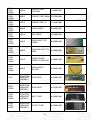
Model:
X1130/X1230/X1230S/X1235/X1230K series
Version: Rev2
First Edition (Dec 2008)
RESTRICTIONS ON USE OF MATERIALS:
1
Index
REVISION LIST .................................................................................................................... 3
CHAPTER 1
SYSTEM SPECIFICATION ......................................................................... 4
Product Specification .................................................................................................................... 4
Electrical Specification.............................................................................................10
Power Supply Specification.....................................................................................14
System Block Diagram ............................................................................................................... 15
Product Overview ........................................................................................................................ 16
CHAPTER 2
SYSTEM UTILITIES.................................................................................. 20
Firmware Upgrade SOP............................................................................................................. 20
Method to enter factory menu ................................................................................................... 27
EDID Upgrade SOP .................................................................................................................... 28
Serial Number Upgrade SOP.................................................................................................... 31
CHAPTER 3
SYSTEM DISASSEMBLING AND REPLACEMENT ................................ 33
Main Unit Disassembling............................................................................................................ 33
Module Assembly Key Point - Optical Engine ........................................................................ 38
Module Assembly Key Point – Mechanical ............................................................................. 51
CHAPTER 4
TROUBLESHOOTING.............................................................................. 59
System Analysis .......................................................................................................................... 59
Optical Problems Checking Items ............................................................................................ 60
Power Supply Problems Checking Flow ................................................................................. 62
LED Messages Definition........................................................................................................... 64
Error Count Messages Definition.............................................................................................. 66
RS232 Connection...................................................................................................................... 67
Adjustment / Alignment Procedure ........................................................................................... 69
CHAPTER 5
FRU LIST .................................................................................................. 75
Exploded Diagram....................................................................................................................... 75
Module 1 – Total Exploded View............................................................................................... 75
Module 2 – ASSY UPPER CASE ............................................................................................. 77
Module 3 – ASSY LOWER CASE ............................................................................................ 78
Module 4 – ASSY FRONT CASE ............................................................................................. 79
FRU List ........................................................................................................................................ 80
APPENDIX A - CODE LIST: IR / RS232 / DDC DATA........................................................ 84
1. Remote Control Code: ........................................................................................................... 84
2. RS-232 Command Code ....................................................................................................... 85
3. DDC Data:................................................................................................................................ 87
2
Revision List
Version
Release Date
Rev0
2008.12.23
Rev1
2009.01.07
Rev2
2009.02.23
Revision History
First Release
(1) Update Ch1- 4.0 Packaging data
(2) Add Ch2- Serial Number Upgrade SOP
(3) Add Ch5- FRU List
Add X1235/X1230K different part :
(1) Ch1- SPEC,
(2) Ch2- Serial Number Upgrade SOP
(3) Ch3- Disassembly process, Module Assembly Key
Point
(4) Appd. A- DDC table
3
Vendor Model
Name
Chapter 1
System Specification
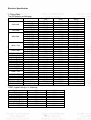
Product Specification
1.0
2.0
3.0
Optical Performance
Image Quality
Mechanical Specification
4.0
5.0
6.0
7.0
Packaging
Thermal Specification
Environmental
Regulatory
8.0
9.0
10.0
11.0
Reliability
Power Requirements
Panel Specification
Compatibility
12.0
13.0
14.0
Image Interface
Control Interface
User Interface
4
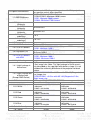
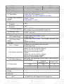
1.0 Optical Performance
1.1 ANSI Brightness
1.2 Brightness
Uniformity
1.2.1 ANSI
Uniformity
1.2.2 JBMA
Uniformity
1.2.3 Upper-Down
unbalance
1.2.4 Left-Right
unbalance
1.3 Contrast Ratio
1.3.1 ANSI Contrast
1.3.2 FOFO Contrast
1.3.3 Dynamic C/R
1.3.4 FOFO Contrast
with APM
Tested under 60” (diagonal) image size with Wide projection
lens position unless other specified.
X1130 : Minimum 1840 Lumens
X1230/X1230S : Minimum 1920 Lumens
X1235 : Minimum 2080 Lumens
X1230K : Minimum 1760 Lumens
Minimum 55%
Minimum 75%
0.5~2
0.6~1.67
Minimum 150:1
X1130/X1230/X1230S/X1230K : Minimum 1200:1
X1235 : Minimum 1450:1
Only for X1130/ X1230/X1230S :
Minimum 1450:1
X1130/X1230/X1230S : None
X1235 : Minimum 1600:1
X1230K : Minimum 1300:1
1.4 Light Leakage
1.4.1 Light Leakage in
Active Area
1.4.2 Light Leakage out
of Active Area
(Except DMD Defect)
1.5 Color
1.5.1 White
1.5.2 Red
1.5.3 Green
1.5.4 Blue
1.6 Color Uniformity
1.6.1 White
<0.5 lux compared to center point within 60” (Diagonal at
2.3m) image size. Note: This light leakage in Active area is
only described as the spot light with obvious shape. It is not
included the uniformity difference of the projector for black
pattern.
X1130/ X1230/X1230S : <0.65 lux with 53”~80“(Diagonal at
2m) image size.
X1235/X1230K : <0.5 lux with 60”~80“(Diagonal at 2.3m,
Wide) image size.
C/W angle : R80Y37W55C28B70G90
X
Y
X1130/X1230/X1235/X1230K :
0.309±0.04
X1230S : 0.313±0.04
X1130/X1230/X1235/X1230K :
0.645±0.04
X1230S : 0.640±0.04
X1130/X1230/X1235/X1230K :
0.344±0.04
X1230S : 0.345±0.04
X1130/X1230/X1235/X1230K :
0.145±0.04
X1230S : 0.144±0.04
X
0.040
5
X1130/X1230/X1235/X1230K :
0.356±0.04
X1230S : 0.350±0.04
X1130/X1230/X1235/X1230K :
0.341±0.04
X1230S : 0.345±0.04
X1130/X1230/X1235/X1230K :
0.535±0.04
X1230S : 0.533±0.04
X1130/X1230/X1235/X1230K :
0.074±0.04
X1230S : 0.075±0.04
Y
0.040
1.6.2 Red
1.6.3 Green
1.6.4 Blue
1.7 Color Gamut
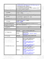
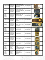
2.0 Image Quality
2.1 Throw Ratio
2.2 Zoom Ratio (tolerance
applied)
2.3 Distortion
2.3.1 Keystone
Distortion
2.3.2 Vertical TV
Distortion
2.3.3 Screen distortion
2.4 Projection Offset
0.040
0.040
0.040
typical 55% compare NTSC
0.040
0.040
0.040
X1130/X1230 : 53”±5% Diagonal at 2m, Wide
X1230S : 54.5”±5% Diagonal at 1m
X1235/X1230K : 52.5”±3% Diagonal at 2m, Wide
X1130/X1230 : 1.1
X1230S : 1(Fixed)
X1235/X1230K : 1.1±2%
<1.0%
<1.0%
Only for X1230S :
|A,B| <=3mm, |C|<=2.5 mm with 60” image size
X1130/X1230/X1235/X1230K :120% ±5%
X1230S : 110% ±5%
2.5 Focus Range
2.5.1 Visible Range
2.5.2 Clearly Focus
Range
X1130/X1230/X1235/X1230K : 1~8 m
X1230S : 0.6~8 m
X1130/X1230/X1235/X1230K : 1.5~6 m(Spec. defined as item
2.6)
X1230S : 0.7~3.6 m
2.6 Focus
(1)If pattern can be uniformly focused, pass!
(2)If not, check 2.6.2
X1130/X1230/X1235/X1230K :
Defocus: R<=3.5; G<=3.0; B<=3.0 pixel
Flare: R<=4.5; G<=4.0; B<=4.0 pixel
Slight flare is not counted as flare.
2.6.2 Defocus and Flare
X1230S :
Defocus: R<=3.5; G<=3.5; B<=3.0 pixel
Flare: R<=4.0; G<=4.0; B<=4.0 pixel
Slight flare is not counted as flare.
Adjust focus from near to far until one corner clear, difference
2.6.3 Focus unbalance
less than 50 cm
Center of
All other area
49”diagonal area
2.7 Lateral Color
R-G
<2/3
<1
G-B
<2/3
<1
R-B
<1
<1
2.8 Image Quality
2.8.1 DMD Image
Quality
2.8.2 Image
Imperfection
2.8.3 Image Shadow or setups
Blur
1. X1130/X1230 : 53” (Diagonal at 2m) image size.
2.6.1 区 Pattern
6
X1230S : 54.5” (Diagonal at 1m) image size.
X1235/X1230K : 60” (Diagonal at 2.3m, Wide) image size.
2. Default preset mode “ Dynamic”
3. Full white pattern to check the image.
Let the projector on the desk (don’t move it up/down or left/
right) and just inspect the pattern.
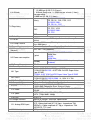
3.0 Mechanical Specification
3.1 Dimensions
264 x 225 x 95 mm (L x W x H)
X1130/X1230/X1235/X1230K : <2300g
3.2 Weight
X1230S : <2500g
3.3 Security Slot
Kensington compatible slot 150N break away force
3.5 Lens Cover
Lens Cover
Fast adjustable foot in front, Adjustable foot and Fixed foot in
3.6 Feet
rear. foot Tilt:0-6∘,right/left: +2.2∘/-0.5
4.0 Packaging
4.1 Outside Dimensions 360 x 180 x 297 mm (L x W x H)
X1130/X1230/X1230K : < 4000g
4.2 Weight
X1230S : < 4100g
X1235 : <3800g
Mechanical component temperature at ambience 0~35℃
5.0 Thermal Specification
5.1 Surface held or
Metal < 65°C; Plastic<85°C
touched for short periods
Metal
Plastic
5.2 Surface which may
be touched
<65°C
<85°C
5.3 Exhaust Air
<95°C
6.0 Environmental
Operating
0~35°C, without condensation
X1130/X1230/X1230S : -20~60°C, without
6.1 Temperature
condensation
Storage
X1235/X1230K : -30~65°C, without
condensation
Operating
10~90%RH, without condensation
6.2 Humidity
Storage
10~90%RH, without condensation
X1130/X1230/X1230S :
Normal mode: 32dBA @ 25°C
Eco mode: 27dBA @ 25°C
X1235 :
Typical
Normal mode: 33dBA @ 25°C
Eco mode: 28dBA @ 25°C
X1230K :
Normal mode: 34dBA @ 25°C
Eco mode: 29dBA @ 25°C
6.3 Audible Noise Level
X1130/X1230/X1230S :
Normal mode: 34dBA @ 25°C
Eco mode: 29dBA @ 25°C
X1235 :
Maximum
Normal mode: 35dBA @ 25°C
Eco mode: 30dBA @ 25°C
X1230K :
Normal mode: 36dBA @ 25°C
Eco mode: 31dBA @ 25°C
∘
7
6.4 Altitude
7.0 Regulatory
Operating:
1. 12,000 feet @ 25°C (3.5 hours)
2. Altitude Ramp rate: <= 3500 feet per minute (1 hour)
Non-operating:
40,000 feet @ -30 °C (1 hour)
X1130/X1230/X1230S :
Safety
CB, GS, UL, CUL, PSE, CCC
X1235/X1230K :
CB, GS, UL, CCC
X1130/X1230/X1230S :
CE, FCC, VCCI
EMC
X1235/X1230K :
CE, FCC
ESD
8.0 Reliability
8.1 MTBF
8.2 Lamp Lifetime
9.0 Power Requirements
9.1 Power Supply
(Normal)
40000 hours except DMD chip, Color wheel, Lamp, Fan and
Ballast
Normal : 3000 hours (50% brightness maintenance)
Eco: 4000 hours
Adhere to Section “Power Supply Specification”
VAC 100 – 240 (50/60Hz),
X1130/X1230/X1230S/X1230K :
280W Max.
X1235 :
285W Max.
5W Max. (X1235/X1230K :loop through is
disabled)
Typical
9.2 Power consumption
Standby
9.3 Power Connector
10.0 Panel Specification
10.1 Type
10.2 Pixels
10.3 Color Depth
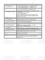
11.0 Compatibility
11.1 PC
11.2 Video
11.3 YpbPr
11.4 DDC
12.0 Image Interface
12.1 Analog RGB Input
12.2 Video Input
IEC-06
X1130 : 0.55” SVGA LVDS Type-X DMD
X1230/X1230S/X1235 : 0.55” XGA 2xLVDS Super Value
Type-X DMD
X1230K : 0.55” XGA 2xLVDS Super Value Type-X DMD
X1130 : H: 800 X V: 600
X1230/X1230S/X1235/X1230K : H: 1024 X V: 768
24 Bits (16770000 colors)
Adhere to Section “Electrical Specification”
PC Compatible 640X480 1024X768, compressed
1920X1080; Composite-Sync; Sync-on-Green
NTSC/ NTSC4.43/ PAL (Including PAL-M, PAL-N)/ SECAM/
PAL60/
NTSC (480i)/ 480p/ PAL (576i)/ 576p,
HDTV (720p/1080i/ 1080p)
EDID 1.3
Adhere to Section “Electrical Specification”
15 pin D-Sub (Female) x 1
G(Y): Video amplitude 0.7/1.0 Vp-p : Impedance 75Ω
RB(CbCr): Video amplitude 0.7 Vp-p : Impedance 75Ω
HD/VD/CS: TTL Level
RCA jack (Yellow)
8
12.3 S-Video Input
12.4 YPbPr Input
12.5 Analog RGB Output
Video amplitude 1.0 Vp-p : Impedance 75Ω
4 pin Mini-Din (Female)
Y: Luminance amplitude 1.0 Vp-p : Impedance 75Ω
C: Chroma amplitude 0.286 Vp-p : Impedance 75Ω
15 pin D-Sub (Female) x 1
Y: Luminance amplitude 1.0 Vp-p: Impedance 75Ω
PbPr/CbCr: Chroma amplitude 0.7 Vp-p : Impedance 75Ω
X1130 : None
X1230/X1230S/X1235/X1230K :
15 pin D-Sub (Female) x 1
G(Y): Video amplitude 0.7/1.0 Vp-p : Impedance 75Ω
RB(CbCr): Video amplitude 0.7 Vp-p : Impedance 75Ω
HD/VD/CS: TTL Level
13.0 Control Interface
13.1 IR Receiver
13.2 Serial Connector
14.0 User Interface
14.1 Operator Keypad
14.2 Indicators
14.3 Electric Keystone
15.0 Audio
15.1 PC Audio Input
15.2 Audio output
15.3 Speaker
IR Receiver x 2 (Front/Top)
Angle: ±0° Distance 0~10m ; ±40° Distance 0~8m
RS232 Mini DIN 3pin,
command table adhere to Appendix A
Adhere to Section “Electrical Specification”
9 Keys:
Power ; Source ; Resync ; e ; Menu ; Left ; Right ;
Up(Keystone-) ; Down(Keystone+)
3 LEDs:
Power On/Off Status; Lamp Status; Temperature Status
Manual and Auto vertical keystone and adjustable range ±40°
X1130 : None
X1230/X1230S/X1235/X1230K : see 15.1~15.3
Φ3.5mm stereo mini jack
500mVrms 10 KΩ or more
Φ3.5mm mono mini jack
X1130 : None
X1230/X1230S/X1235/X1230K : Speaker 8Ω 5W X 1,
Amplifier 1W X1
9
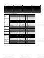
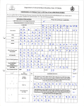
Electrical Specification
1. Timing Table
The PC timing is as following:
Resolution
640 x 480
720 x 400
800 x 600
1024 x 768
1152 x 864
1280 x 1024
1280 x 960
640x480@60Hz
640x480@67Hz
800x600@60Hz
832x624@75Hz
1024x768@60Hz
1024x768@75Hz
1152x870@75Hz
1280 x 768
1280 x 720
1280 x 800
1440 x 900
1366 x 768
1024 x 576
1024 x 600
Mode
VGA_60
VGA_72
VGA_75
VGA_85
720x400_70
720x400_85
SVGA_56
SVGA_60
SVGA_72
SVGA_75
SVGA_85
XGA_60
XGA_70
XGA_75
XGA_85
SXGA_70
SXGA_75
SXGA_60
1280 x 960_60
Mac G4
MAC13
Mac G4
MAC16
Mac G4
MAC19
MAC21
WXGA_60
WXGA_75
WXGA_60
WXGA_60
WXGA+_60
acer_16:9
acer_timing
acer_timing
Refresh rate
(Hz)
59.940
72.809
75.000
85.008
70.087
85.0
56.0
60.317
72.188
75.000
85.061
60.004
70.069
75.029
84.997
70.0
75.0
60.020
60.000
59.94
66.667
60.317
74.546
60.004
75.020
75.06
60.0
74.89
59.94
59.81
59.887
59.79
59.899
60.0
H-frequency
(kHz)
31.469
37.861
37.500
43.269
31.469
37.9
35.2
37.879
48.077
46.875
53.674
48.363
56.476
60.023
68.667
63.8
67.5
63.981
60.000
31.469
35.000
37.879
49.722
48.363
60.241
68.68
47.4
60.29
45.0
49.702
55.935
47.712
35.88
37.5
YPbPr support timing is as following:
Signal format
480i(525i)@60Hz
480p(525p)@60Hz
576i(625i)@50Hz
576p(625p)@50Hz
720p(750p)@60Hz
720p(750p)@50Hz
1080i(1125i)@60Hz
1080i(1125i)@50Hz
fh(kHz)
15.73
31.47
15.63
31.25
45.00
37.50
33.75
28.13
fv(Hz)
59.94
59.94
50.00
50.00
60.00
50.00
60.00
50.00
10
Clock
(MHz)
25.175
31.500
31.500
36.000
28.3221
35.5
36.0
40.000
50.000
49.500
56.250
65.000
75.000
78.750
94.500
94.5
108.0
108.000
108
25.17
30.240
40.0
57.280
65.0
80.000
100.00
68.25
102.25
74.25
83.5
106.500
85.5
46.5
50.4
Video, S-Video support timing is as following:
Video mode
NTSC
PAL
SECAM
PAL-M
PAL-N
PAL-60
NTSC4.43
fh(kHz)
15.73
15.63
15.63
15.73
15.63
15.73
15.73
fv(Hz)
60
50
50
60
50
60
60
fsc(MHz)
3.58
4.43
4.25 or 4.41
3.58
3.58
4.43
4.43
2. Characteristics of inputs/outputs
Signal
RDATA
GDATA
BDATA
Parameter
Impedance
Amplitude
Black pedestal
Pixel Clock
GDATA_SOG Impedance
Amplitude
Video amplitude
Sync amplitude
Black pedestal
Pixel Clock
HDATA
Impedance
Amplitude, low level
Amplitude, high level
Frequency
VDATA
Impedance
Amplitude, low level
Amplitude, high level
Frequency
SDADATA
Amplitude, low level
Amplitude, high level
SCLDATA
Amplitude, low level
Amplitude, high level
RXD
Amplitude
TXD
Amplitude
CVBS
Amplitude, total (video+ sync)
Luminance
Amplitude, video
Amplitude, sync
Impedance
CVBS Chroma Amplitude
Impedance
Audio
Impedance (audio in)
(Only for
Amplitude (audio in)
X1230/X1230S Bandwidth
)
S/N Ratio
Total Harmonic Distortion
Min
Type
75
0.7
0
110
75
1
0.7
0.3
0
110
1
0
2.5
31
1
0
2.5
48
0
2.5
0
2.5
-25
-13.2
1
0.7
0.3
75
300
75
10
0
300Hz
40
11
Max
Ohm
Volts peak-to-peak
Volts
M Hz
Ohm
Volts peak-to-peak
Volts peak-to-peak
Volts peak-to-peak
Volts
M Hz
K ohm
0.8
volt
5
Volt
93
K Hz
K ohm
0.8
volt
5
Volt
86
Hz
0.8
volt
5
Volt
0.8
volt
5
Volt
25
Volt
13.2
Volt
Volts peak to peak
Volts peak to peak
Volts peak to peak
ohm
m Volts peak to peak
ohm
Kohm
0.50 Volts rms
16kHz
%
10 %
3. Electrical Interface Character
Interface Definition
15 pin definition of the mini D-sub male for DDC2B protocol
5
1
6
10
15
11
Pin
1
Pin
2
5
Definition
Red video
(Pr)
NC
Pin
3
6
Definition
Green Video
(Y)
Red Video Return
9
DDCP 5V
10
GND
11
13
Horizontal
Sync
14
Vertical Sync
15
7
Definition
Blue Video
(Pb)
Green Video
Return
GND
Data clock
(SCL)
Video Input
1
Composite input
Pin
Definition
1
Composite video input
S-Video input
4
3
2
1
Pin
1
2
3
4
Description
GND
GND
Luminance
Chroma
Control Port
Pin
1
2
3
Description
TX
RX
GND
12
Pin
4
Definition
NC
8
Blue Video
Return
Bi-directional
data (SDA)
12
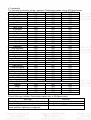
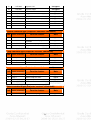
4. Functionality
The Following functionality will be supported: (Detailed description refer to SW Specification)
Functionality
Data (Computer)
Video/S-Video
YPbPr/YCbCr
Display Mode
YES
YES
YES
Brightness
YES
YES
YES
Contrast
YES
YES
YES
Saturation
NO
YES
YES
Tint
NO
YES
YES
Sharpness
NO
YES
YES
Color Temp
YES
YES
YES
H. Position
YES
NO
NO
V. Position
YES
NO
NO
H. Phase
YES
NO
NO
H. Size
YES
NO
NO
DeGamma
YES
YES
YES
ColorR
YES
YES
YES
ColorG
YES
YES
YES
ColorB
YES
YES
YES
Projection
YES
YES
YES
Auto Keystone
YES
YES
YES
Keystone
YES
YES
YES
Source Lock
YES
YES
YES
Location
YES
YES
YES
Security
YES
YES
YES
Reset
YES
YES
YES
Closed Caption
NO
YES(NTSC)
NO
Ecco Mode
YES
YES
YES
High Altitude
YES
YES
YES
Lamp Reminding
YES
YES
YES
Lamp Hour Reset
YES
YES
YES
Timer Location
YES
YES
YES
Timer Start (or Stop)
YES
YES
YES
Timer Period (Minutes)
YES
YES
YES
Timer Display
YES
YES
YES
Language
YES
YES
YES
Below items for X1230/X1230S/X1235/X1230K
Volume
YES
YES
YES
Mute
YES
YES
YES
Power On/Off Volume
YES
YES
YES
Alarm Volume
YES
YES
YES
Timer Volume
YES
YES
YES
External Message indicator (Detailed description refer to SW Specification)
Message
Occasion
D-sub /Composite Video /S-Video Searching
Input Not Supported
Lamp is approaching the end of its useful life in full
power operation. Replacement suggested!
13
The system does not detect the signal
The signal is over the specification
Lamp Hour is at 2970 hours
Power Supply Specification
1. Input Power Specification
Specification
Input Voltage Range
Frequency Range
Power Consumption
Regulation Efficiency
Description
The unit shall meet all the operating requirements with the range 90
~ 264 VAC
The unit shall meet all the operating requirements with an input
frequency range :
X1130/X1230/X1230S/X1235 : 50 Hz ~ 60 Hz
X1230K : 47 Hz ~ 63 Hz
Normal operation:
X1130/X1230/X1230S/X1230K : 280W (Max)
X1235 : 285W (Max)
standby mode: < 5W(for X1235/X1230K : loop through is disabled)
80 % (typical) measuring at 115Vac and full load
2. Output Power Requirement
The power supply can provide DC output as below:
NO.
Voltage Regulation
Load Current Range
1
+12 V
0.15 A ~ 2.5 A
±10 %
Ripple & Noise
300 mV
3. Lamp Power specifications
Specification
Applicable Lamp
Description
X1130/X1230/X1230S/X1230K : Philips 189W, AC operation.
X1235 : Philips 210W, AC operation. Applicable ballast = 200W.
Starting pulse from
Ignitor
14
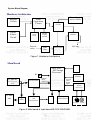
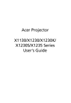
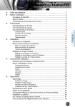
System Block Diagram
Hardware Architecture
Keypad
Circuit
Thermal break
sensor Circuit
Main
Operation
Circuit
Input
Source
Circuit
CW Index
sensor
board
Fan Driver
Circuit
Ballast
Module
Lamp
Door
switch
From AC
socket
To Lamp
PFC Circuit
EMI
Filter
Figure 1 Hardware Architecture
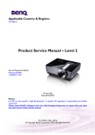
Main Board
RAM
DDP ASIC
DLP Image
Processor
IR
D-Sub in
A/D converter
RGB analog signal
YPbPr
D-Sub
out
Triple
video
DMD Power
and
Reset Driver
32 M Flash
Memory
I
RGB888
24bits
Digital Signal
DMD
YUV422
10bits
Digital
Signal
NTSC/PAL
/SECAM
Video Decoder
Color Wheel
Motor Driver
MBRST(0:15)
S-Video CVBS
Figure 2 Main board & Input board BLOCK DIAGRAM
15
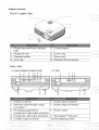
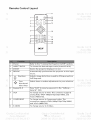
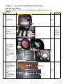
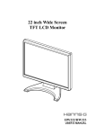
Product Overview
16
17
18
19
Chapter 2
System Utilities
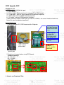
Firmware Upgrade SOP
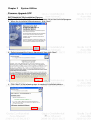
DLP Composer LIte Installation Process
1. Double click the Setup file for DLP Composer Lite to start to install program.
2. When the Installation Wizard appears, click “Next”.
3. Select to accept the License Agreement, than click “Next”
4. Click “Next” in the following steps to continue installation process.
20
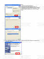
Note:
The default installation directory is:
C:\Program Files\DLP Composer Lite 7.2
If you want to install to a different directory (perhaps
alongside a prior release of DLP Composer™ Lite),
click the "Browse" button on the "Select Features"
page.
5. When finishing installation, click “Finish”, and then restart your computer to complete the
installation process.
21
(1) Select Library
1. When start to use this program to download at first time, you need to check if the library
folder is existed under the path of Library.
Click “Browse” to
select path for
library files
Click the library
folder to assign the
path.
Then Click “OK”.
2. Check if there are library files in the assigned path. If not, unzip the file
“library_20090214.zip” into the path.
(2) Download Procedure
How to download
22
Hardware required
1. Standard RS232 Download cable
2. Personal computer or laptop computer
Software required
1. DLP Composer Lite program
2. New version FW
Download procedure
1. Prepare the download equipment: RS232 cable connect to PC and projector
2. Plug power cord into projector , and the projector will be in stand by mode
3. Execute DLP composer Lite program from your “START” ->”Program files” menu of
Windows.
“START” menu
->”Program files”
->DLP Composer
Lite
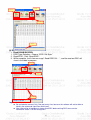
4. Check communication is RS232 (Serial Port):
Select “Edit”->”Preference”->”Communications”->”Serial Port”
Then select the connection port between projector and your computer.
Select the connection port
between projector and
your computer.
5. Select “Flash Loader” and make sure to check on “Skip boot Loader Area”. (Select
32KB).
23
Caution: do not interrupt download like unplug power cable.
If you skip boot loader Area and interrupt download, Projector would not turn on anymore.
6. Click on “Flash Loader” and “Browse”->select file->”Open” to select the path of the image
file(new version firmware)
24
7. Click “Reset Bus” and then check the status that shows “Bus Reset”.
8. Select “Start download” and three LED light orange color
25
When FW is
downloading,
“Start Download”
becomes disabled.
9. After download complete, program will show “Download complete” message, and
projector will reset to stand by mode.
10. If program pops out another error message after “Download complete” message
appearing, it’s ok to skip the error message.
11. After download completing, it’s necessary to unplug power cord, then re-plug power cord
and restart projector.
26
Method to enter factory menu
1.
2.
Press keypad Power and image will show Power Down OSD function
Press keypad Left twice then press Menu, then enter the Factory mode.
Step 1
Step 2
27
EDID Upgrade SOP
Equipment List
1. PC : with parallel (printer) port
2. EDID Board
3. Printer cable : 25pin male-female (connect PC to EDID board)
4. D-sub cable* : with full 15pin (connect EDID board to Projector)
5. HDMI cable*(connect EDID board to Projector)
6. DVI cable* (connect EDID board to Projector)
(*Note: Not every model’s EDID input (D-sub, DVI, HDMI) is the same. Need to check what
kind of file you need before download.)
Setup Equipment
1. Connect between PC, EDID board and the Projector:
Link to Projector : For
DVI-D DDC download
(no need in X1130/ X1230/
X1230S/ X1235/ X1230K
series)
Link to Projector :
For HDMI DDC
download (no need in
X1130/ X1230/ X1230S/
X1235/ X1230K series)
Please ignore this
connector
“25pin male-female
cable” (normal
printer cable)
EDID board
PC with parallel
(printer) port
2. Need to set Jumper before using EDID board :
<Jumper setting :>
J6 : 1,2 short
J8 : 1,2 short
J10 : short
3. How to use Download Tool :
28
Link to Main
board :
For D-sub DDC
download
Software Installation, Un-installation :
Unzip the “Q-EDID” program files in the same directory.
Install Q-EDID tool : Execute “Install Q-EDID.BAT” to install & register EDID Board into
the computer.
Un-install Q-EDID tool : If you want to uninstall this tool, execute “Uninstall
Q-EDID.BAT”, then it will remove EDID Board from the computer.
How to use Download Tool :
(1) Execute EDID Tools V0.16:
1. Run “Q-EDID-V016.exe”.
2.
Program will appear as below picture.
(2) Write EDID:
• When write D-SUB/DVI EDID:
1. EDID Type Selection : Choose ‘‘EDID 128 Bytes’’.
2. Open Files : Click “Open File” to select file “*.DDC”
(Note : If your DDC file name is not like “*.DDC” (e.g. “*.2dc”), please rename it to “*.DDC”)
3. Write EDID : Click “Write EDID”, and it will execute writing process.
4. While complete, it will show message as ’’Write EDID OK…’’.
(Note : Check cable connection before write. It will show Write EDID OK even the connection is
not stable.)
29
Step3
Step2
Step1
Step4
(3) Read EDID:
• Read D-SUB/DVI EDID:
1. EDID Type Selection : Choose ‘‘EDID 128 Bytes’’
2. Read EDID : Click “Read EDID”.
3. While complete, it will show message’’ Read EDID OK… ‘’, and the read-out DDC will
show in the table in program.
Step2
Step1
Step3
Ste
Important Note :
Be reminded to connect Only One port every time, because the software will not be able to
identify the command signal from which port.
After connecting all equipment, always read DDC before writing DDC to ensure the
connection status is OK for writing DDC.
30
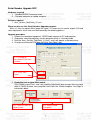
Serial Number Upgrade SOP
Hardware required
1. Standard RS232 Download cable
2. Personal computer or laptop computer
Software required
1. Acer_Service_Tool(Data)_3.1.exe
When need to use this Serial Number Upgrade program:
When it’s time to replace Main board for repair, it’s necessary to rewrite original S/N and
some adjustment values into new Main board by the following process.
Upgrade procedure
1. Prepare the download equipment: RS232 cable connect to PC and projector
2. Plug power cord into projector, and the projector will be in stand by mode.
3. Execute “Acer_Service_Tool(Data)_3.1.exe”, and it will appear as below picture.
4. Change to connected COM port and Click “Port Open” icon.
4-1. Change to
connected COM Port
number
4-2. Click “Port
Open”
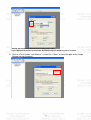
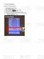
5. Read data from original Main board:
Click “Read system Data”, and it will read the Adjustment data (except Auto keystone
data) & Serial Number from projector and show the “Read complete” message in
information block.
5-1. Click this icon to
read all data
5-2. Show “Read
Complete!”
31
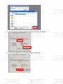
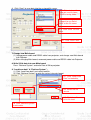
6. Click “Save” to save data into the assigned file name.
6-2. This window will
pop out, and it shows
the file saving folder.
6-3. Enter file name here.
Suggest to use Serial
Num as the file name.
6-4. Click “Save” to save
data.
6-1. Click “Save” icon.
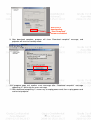
7. Change new Main board:
(1) Unplug power cable and RS232 cable from projector, and change new Main board
into Projector.
(2) After changing Main board, reconnect power cable and RS232 cable into Projector.
8. Write S/N & data into new Main board:
Press “Retrieve System” and write Data & SN to projector.
9. “Load from data” & “Retrieve System” :
(1) Click “Load from data” and select load file.
(2) Click “Retrieve System” to write the values into main board.
9-1. Click “Load From
Data” to load data.
9-2. Select the file
source
9-3. Click “Load” to
finish file load.
10. Click “Retrieve System”
to write data.
32
Chapter 3
System Disassembling and Replacement
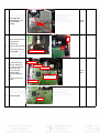
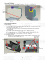
Main Unit Disassembling
Tool : Screw Driver --Hex (#4-40) and Cross(Mechanical : M3,M4, Opt.Engine :M2)
Process :
Step Discription
Tool
5
Notice
1
3
1
Disassemble the
screw*5(M3*7L).
screw
driver
4
2
2
(1) Take off the the IR
sensor wire from
mainboard,
(2) Take off upper case
module.
When taking
off upper
case module,
be careful not
to break the
IR-M/B wire.
keypad Rubber
keypad bracket
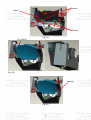
3
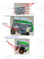
(1) Take off the case
outlet case module
(2) Take off the front
case module
(3) (For
X1230/X1230S/X1230S/
X1230K):
Take off the screw*4
(M3*7L) and speaker
from the outlet case
module
FRONT
IR BD
screw
driver
Two sponge
4
1
2
3
Three long sponge
<For X1130> :
Disassemble the
screw*2(STAND OFF
XH4#-40), and take off
the rear case.
4
<For
X1230/X1230S/X1235/X
1230K> :
Disassemble the
screw*4(STAND OFF
XH4#-40), and take off
the rear case.
rear case
1
2
screw
driver
1
2
3
rear case
4
33
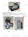
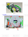
5
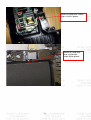
6
Disassemble the
screw*5(M3*5L), and
take off the M/B
shielding.
(1)Take off the long wire
(one of twin fan
wire)from clip
(2) Disassemble the twin
fan.
(3)Take off the twin fan
wire from M/B.
screw
driver
screw*5
twin
fan
take off this long wire first
C/W sensor wire
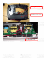
7
8
(1) Take off the C/W
FPC wire, blower fan
wire, C/W sensor wire,
Ballast 5-Pin wire,
speaker wire (For
X1230/X1230S/
X1235/X1230K) from
M/B.
(2) Take off inlet case
module.
C/W FPC wire
blower fan wire
screw
driver
speaker wire
(For X1230/X1230S)
Ballast 5Pin wire
Take off the M/B
Main BD
34
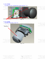
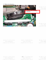
9
(1) Disassemble the
screw*2(M3*6L), and
take off the lamp door.
(2) Disassemble the
screw*1(M3*4L) and
lamp wire, and take off
the lamp module.
1
2
screw
driver
screw*1
2
1
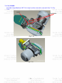
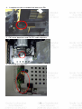
(1) Disassemble the
screw*3(M3*8L).
(2) Disassemble the
10
grounding screw*1
(M4*6L), and take off the
Power B/D SHD.
screw
driver
3
grounding screw *1
blower fan's
thermal wire
screw*1
(1) Disassemble the
wire*2 and screw*1(
11 M3*7L),
(2) Take off the power
BD and ballast Mylar.
Ballast Mylar
screw
driver
ballast
wire
screw*1
(1) Disassemble the
screw*2(M3*7L), and
take off the lamp box.
12
(2) Disassembly the
screw*2(M3*8L), and
take off the blower fan.
screw*1
screw*1
screw*1
screw
driver
<For X1130/X1230/X1235/X1230K>
1
Disassemble the
13 screw*3(M3*7L), and
take off the OPT eng .
3
<For X1230S>
2
定位
点
2
1
anchor
point
3
35
定位
点
anchor
point
screw
driver
3pin wire
1
Disassemble the
14 screw*2(M3*5L), the
ballast BD, and wire*3.
screw
driver
5pin wire
2pin wire
2
shielding
push button
15
Take off the shielding
and push button.
screw
driver
<For X1130/X1230/X1235/X1230K>
<For X1230S>
focus ring
focus ring
(1)Take off the gasket*2.
16 (2)Disassemble the
Focus Ring.
screw
driver
gasket*2
gasket*2
2
<For X1130/X1230/X1235/X1230K>
1
<For X1130/X1230/
X1235/X1230K>:
(1)Take off Zoom Ring
and Ring
screw*2(M2*3L).
(2)Take off the LENS
screw*3(M3*4L) and the
17
Projection Lens.
1
2
3
<For X1230S>
screw
driver
2
<For X1230S>:
(1)Take off Focus Ring.
(2)Take off the LENS
screw*4(M3*6L) and
Mylar
4
mylar
focus ring
1
3
<For X1230S>:
(1)Disassemble the
18 screw*3(M3*4L), and
take off the frame lens
(2)Take off the mylar
3
1
2
mylar
36
Disassemble the
screw*4(M3*15.15L),
19 and take off the HSINK
and DMD chip BD with
DMD Chip.
(1)Disassemble the
baffle DMD.
20 (2)Disassemble the
screw*3(M3*4L) and take
off the CW module.
2
4
screw
driver
1
3
1
CW module
2
screw
driver
3
baffle DMD
Rotate to open the
21 switch on socket, and
take off the DMD chip.
(1)Disassemble ILL
module
screw*2(M2.5*5L).
(2)Take off
22
screw*1(M2*8L), FM
holder, fold mirror, FM
clip*2, clip CM front, clip
CM side and sponge.
screw
driver
1
2
sponge
screw*1
screw*1
(1)Disassembly the Light
Pipe clip screw*1
(M2*3L).
23
(2)Take off the LP
module and LP
screw*2(M2*8L).
screw
driver
L/P
screw
driver
1
2
37
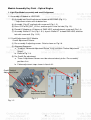
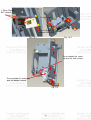
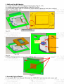
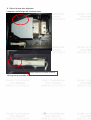
Module Assembly Key Point - Optical Engine
1. Light Pipe Module assembly and overfill alignment
1.1 Assembly LP Module to HSG DMD
(3) Assembly two Overfill adjustment screws to HSG DMD (Fig. 1-1).
** Adjustment criteria refer to below item
(4) Assembly “Clip LP” and lock with screw well (Fig. 1-2).
(5) Press CLIP of RE_BKT_LP first, and then push it into the hole (Fig. 1-3).
(6) Placed LP Module on LP datum of “DMD HSG” and adjustment screw well (Fig.1-4).
(7) Assembly “Baffle LP” first (Fig. 1-5-1) & push “Baffle LP” to hook DMD HSG, and then
lock with screw well (Fig. 1-5-2).
1.2 Overfill Adjustment @ LP Module
Overfill Adjustment Criteria:
(1) Pre-assembly 2 adjusting screws. Criteria shown as Fig.1-6.
(2) Alignment Sequence:
a. To adjust “Horizontal Adjustment Screw” firstly, and then “Vertical Adjustment
Screw”.
b. Refer to Fig. 1-6.
(3) For Overfill Re-adjustment:
a. Those 2 Adjustment Screws must be released closely to the “Pre-assembly”
positions first.
b. Follow adjustment steps shown in Item 4.6-ii.
Clip LP
Overfill Vertical
Adjustment Screw
Overfill Horizontal
Adjustment Screw
Fig. 1-1
Fig. 1-2
38
1. Press down
the Clip
2. Insert the
LP Module
Fig. 1-3
Fig. 1-4
LP Datum of DMD HSG
39
Overfill adjustment screws
1. Place Clips on
BKT surface
3. Lock screw
2. Push Baffle LP
to hook DMD HSG
Fig. 1-5-1
Fig. 1-5-2
Pre assemble this screw
not over the side surface.
Pre assemble this screw not
over the bottom surface.
Fig. 1-6
40
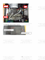
2. Assembly FM Module:
Place FM on “HLD FM” surface(Fig. 2-1) and use “Clip FM” to fix FM(Fig. 2-2).
Clip FM hook
the punch points
Touch the
side surface
Fig. 2-1
Fig. 2-2
3. Assembly HSG ILL Module:
3.1 CM Assembly
I.
Insert “Clip CM Side” first, and then place “Clip Front CM” to fixed-shaft of ILL SUB
before locking screw (Fig. 3-1, Fig. 3-2).
II. Assemble CM to HSG ILL and to make CM contact three datum on the HSG ILL
Well (Fig. 3-3).
III. Assemble “CLIP TOP CM” (with forceps) to the “HSG IL” (Fig. 3-4,).
IV. To check and make sure “CLIP of CM” hooks the HSG ILL very Well (Fig. 3-5).
V. Paste “Sponge tube AL” on cannelure of” HSG ILL” (Fig. 3-6).
6.2 FM Module Assembly
1.
FM Module must be placed to fixed shaft and on the datum surface of “ILL SUB”
Fixed shafts
and then lock with screw well (Fig. 3-7).
of ILL SUB
Clip CM Side
Screw
8F.1A752.3R0
Fig. 3-1
Fig. 3-2
41
Datum3
Datum1
Datum2
Fig. 3-3
Clip UP CM
Fig. 3-4
Fig. 3-5
Sponge
Fig. 3-6
42
screw
Fig. 3-7
4. AL, HSG ILL and HSG DMD Assembly:
4.1 Placed “AL” on the “HSG DMD”. The “raised surface” of “AL” shall toward “DMD direction”
(Fig. 4-1).
4.2 To assemble ”HSG ILL SUB Module” with “HSG DMD” and cover over on “AL” and the
then lock with screws (Fig. 4-2).
Fixed shafts& holes
AL
screw
DMD Direction
Fig. 4-1
Fig. 4-2
43
5. DMD and Chip B/D Module:
5.1. Judge Chip B/D and DMD alignment keying first (Fig. 5-1, 5-2).
5.2. Alight keying and Assemble DMD to Chip B/D (Fig. 5-3).
5.3. Push DMD slightly and use screwdriver rotate clockwise button to lock (close notation)
DMD on Chip B/D (Fig. 5-4).
Fig. 5-1
Alignment keying
Fig. 5-2
Open notation
Button
Close notation
Fig. 5-3
Fig. 5-4
8.4 Place Damper on the surface of Chip-BD Fig. 5-5.
Damper
.
Fig. 5-5
6. Assembly Optical Engine:
6.1 Assemble “BKT Link Lamp & CW shield” on “DMD HSG” and then lock with screws well
44
(Fig. 6-1).
Screw
Shield CW
BKT Link Lamp
Fig. 6-1
7. Assembly OP ENG
7.1 Assemble “Baffle DMD” to “HSG DMD” (Fig.7-1).
7.2 Assemble Chip B/D Module to “HSG DMD” (Fig. 7-2).
Fixed shafts of
DMD HSG
Fixed holes of
ILL SUB HSG
Fixed shafts of
DMD HSG
Fig.7-1
Fixed holes of DMD
Fig.7-2
7.3 Assemble Thermal Pad & Gasket Hest-sink then place contact DMD (Fig. 7-3).
(1) Pre-fastening Sequence: [ 1 ] - [ 2 ] - [ 3 ] - [ 4 ].
(2) Fastening Sequence: [ 4 ] - [ 3 ] - [ 2 ] - [ 1 ].
(3) Screw Torque must be confirmed to be 6 kg-cm.
45
Screw
○
3
2
4
○
1
Gasket
Fig. 7-3
7.4 Assemble “CW Module” to “DMD HSG” and lock with screws well (Fig.7-4).
Screw
Fixed shafts
of DMD HSG
Fig.7-4
7.5 For X1130/X1230/X1235/X1230K :
Assemble “PL Lens” and lock with screws well (Fig. 7-5).
Screw
Fig. 7-5
46
Ring Zoom
Screw
Fig. 7-6
Ring Focus
Fig. 7-7
7.6 For X1130/X1230/X1235/X1230K :
Assemble Lamp Module to “BKT Link Lamp” and then lock with screw well (Fig. 7-8, Fig.
7-9).
Screw
Fixed shafts
Fig. 7-8
47
Fig. 7-9
7.7 For X1230S :
Assemble “Frame Lens Wide” and lock with screws well (Fig. 7-10).
Fig. 7-10
A Gap for LP
Adjustment
Screws
48
7.8 For X1230S :
Assemble “PL Lens” and lock with screws well (Fig. 7-11).
Screws
Fig. 7-11
7.9 For X1230S :
Assemble “Ring Focus” (Fig.7-12).
Ring Focus
Fig. 7-12
49
7.10 For X1230S :
Assemble Lamp Module to “BKT Link Lamp” and then lock with screw well (Fig.7-13, Fig.
7-14).
Screw
Fixed shafts
Fig. 7-13
Fig. 7-14
50
Module Assembly Key Point – Mechanical
1. lower case and Adjust foot
Spring should be no bend
2. Ballast wire Alignment dressed
Ballast to PWR wire must
go outside this rib
Two screws
51
Ballast to Lamp wire should
align in to this groove
Ballast to Lamp wire
also should align
under Mylar groove
52
First: assy Blower module
Second: assy Mylar Ballast
This cord location is here
53
3. Blower wire alignment
This clip must be screwed by
this direction
54
4.
Lamp box must be assembled into lower case Rib
5. CW sensor board wire and CW FPC cable alignment
6. Grounding wire alignment
55
7. Twin Fan and Speaker wire alignment
8. Front IR wire to MB alignment
Front IR wire should align
in to these grooves
56
9. Ballast to lamp wire alignment
Lamp box should align with the lower case
Lamp connector assemble with rib
10. Eng screw assemble sequence
57
Second
First
Third
11. Lamp Door screw assemble sequence
58
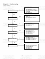
Chapter 4
Troubleshooting
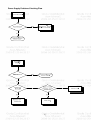
System Analysis
Keypad LED OK
Step:
1. Check Lamp Door
2. Check Power Board and Interlock
3. Check Connection between PWR BD
and Main BD
4. Check Main Board
No
Yes
1.
2.
3.
4.
5.
Check Lampen wire , Lamp wire and
Ballast wire
Check C/W and wire connection
Check Main board
Check Lamp
Check Ballast
1.
2.
3.
Check Input Cable
Check OSD Source set up
Check Main board
1.
2.
3.
4.
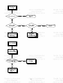
5.
Check OSD Lamp Hours
Check Lamp Door
Check Lamp still light or not?
Check Fan still spin or not?
Check Thermal status
Yes
1.
2.
3.
4.
Check Remote module battery
Check Remote module
Check IR Receiver on Main board
Check IR Receiver on IR board
Yes
1.
Check the connection between Main
BD and Chip BD
Check the connection between OP
engine and DMD Chip
Check Chip board
Check Main board
No
If Power On, Lamp On?
Yes
Yes
No Signal?
No
Yes
Power Auto Turn Off
No
IR Remote Control NG?
No
Pixel Fail?
2.
3.
4.
59
Optical Problems Checking Items
No. Item
Trouble Shooting Guide
1
Brightness
1. Change lamp
2
Uniformity
1. Change lamp
1. Check ADC calibration
3
FOFO Contrast
2.
3.
4.
5.
Check user’s menu brightness & contrast are default
Clean DMD
Clean PL
Check ILL stop assy
1. Clean PL
2. Clean DMD
3. Change PL
4
ANSI Contrast
5
Color
6
Color Uniformity
1. Change lamp
Blue Edge
1. Refer to next page
2. Change CM
3. Change SUB HSG
7
1. Check color wheel delay
2. Check CW 50% point. Replace CW if necessary
1. Refer to next page
8
Blue/Purple Border
9
Focus
10
Dust
11
Horizontal/Vertical
Strips
12
Pixel Fail
2. Change CM
3. Change SUB HSG
1. Change Projection Lens
2. Check PL datum and DMD parallel
Clean DMD
1. Check connector between chip BD and Main BD
2. Re-install DMD with chip BD
3. Check if any pin of C-Spring is missing, damaged or dirty
4. Change new Chip BD/C-Spring
5. Change new DMD
Change new DMD
60
“Blue Edge” Trouble Shooting:
I. Re-adjust “Overfill” first.
For Overfill Re-adjustment:
i. Those 2 Adjustment Screws must be released for around 2 mm first.
ii. Alignment Sequence:
a.
To adjust “Horizontal Adjustment Screw” firstly, then “Vertical Adjustment
Screw”.
b.
Refer to below Figure.
(2) Overfill Vertical
Adjustment Screw
(1) Overfill Horizontal
Adjustment Screw
II. Re-assemble LP module—include LP, LP Baffle, LP clip.
61
Power Supply Problems Checking Flow
62
63
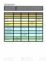
LED Messages Definition
External Status indicator
LED Name
Power LED
Lamp Status LED
Temperature Status LED
Detailed Description
Display the power on/off sequence status
Display the Lamp status (Lamp fail, Lamp spoil etc.)
Display the Thermal status (Fan Fail, Over Temperature, etc.)
Lamp_LED
Red
Temp_LED
Red
Power_LED
Red
Flash ON to OFF
Flash ON to OFF
Flash ON to OFF
Standby
--
--
ON
--
Power button ON
--
--
--
ON
Lamp retry
--
--
--
0.5 second H(On),
0.5 second L(Off)
flashing
Cooling state
--
--
0.5 second H(ON),
0.5 second L(OFF)
flashing
--
--
--
ON
--
ON
ON
ON
--
≧8 ℃
--
ON
--
ON
≧54℃
--
ON
--
ON
--
0.5 second H(On),
0.5 second L(Off)
flashing
--
ON
ON
--
--
ON
0.5 second H(ON),
0.5 second L(OFF)
flashing
--
--
ON
Power Plug
Power button OFF:
Cooling completed;
Standby Mode
Firmware Download
Thermal sensor error (T2
5 ) (Lamp Over
Temperature) OSD shows
“Projector Overheated”
Thermal sensor error (T1
) OSD shows
“Projector Overheated”
Fan lock error OSD
shows red “Fan Fail, Will
automatically turn off
soon”
Lamp error (Lamp,
ballast)
Color Wheel fail
64
Power_LED
Blue
-
Fan 3 :
Blower Fan
Fan 1 :
Lamp Fan
Fan 2 :
Power Fan
Thermal
sensor 1
LED
message
Thermal sensor 2
65
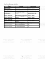
Error Count Messages Definition
Error
Count
Definition
Specification
LAMP Fail error
LAMP OFF
DETECT LAMPLIT
FAN 1 Speed Error
LAMP FAN SPEED ERROR
SPEED OVER ± 20%
BALLAST FAN SPEED
ERROR
BLOWER FAN SPEED
ERROR
SPEED OVER ± 20%
FAN 2 Speed Error
FAN 3 Speed Error
SPEED OVER ± 20%
Sensor 1 Open Error
Main Board SENSOR ERROR DETECT Sensor 1
Sensor 2 Open Error
Power board SENSOR
ERROR
Sensor 1 Short Error
Main Board SENSOR ERROR DETECT Sensor 1
Sensor 2 Short Error
Power board SENSOR
ERROR
DETECT Sensor 2
Temperature 1 Error
over limited temperature
N/A
Temperature 2 Error
over limited temperature
N/A
FAN IC I2C ERROR
I2C communication error
N/A
66
DETECT Sensor 2
RS232 Connection
1. Connection:
Below shows the illustration of connection between PC and Projector.
<CAUTION>
Make sure that your computer and projector are turned off before connection.
Power on the computer first, and then plug the power cord of the projector. (It may
cause Com port incorrect function, if you do not follow this instruction)
Adapters may be necessary depending on the PC connected to this projector. Please
contact with your dealer for further details.
2. Hardware connection
<download cable 1>
<pin assignment for this two end>
67
Interface Settings
RS-232 protocol
Baud Rate
Data Length
Parity Check
Stop Bit
Flow Control
115200 bps
8 bit
None
1 bit
None
Command Category
Refer to Appendix A
68
Adjustment / Alignment Procedure
Content :
1. Color Wheel Delay Alignment
2. Overfill adjustment
3. PC Alignment Procedure
4. YUV Alignment Procedure
5. Keystone Calibration
69
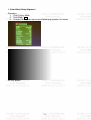
1. Color Wheel Delay Alignment
Procedure:
1. Enter Factory Mode
2. Enter Block 1
3. Change CW Delay by adjusting the following gray pattern to smooth
32 Gray pattern
70
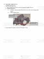
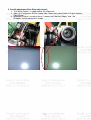
2. Overfill adjustment (Blue Edge adjustment)
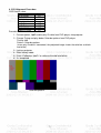
1. “Full White Pattern” is suggested for this alignment.
2. Adjust 2 LP-alignment Screws (upper side / lower front side of Optical Engine) behind
Color Wheel.
3. Alignment Criteria is to adjust these 2 screws until “No Dark Edges” and “ No
Shadows” can be observed in image.
71
3.
PC Alignment Procedure
OSD Default value:
Item
Cal R Offset
Cal G Offset
Cal B Offset
Cal R Gain
Cal G Gain
Cal B Gain
YPbPr R Offset
YPbPr B Offset
Procedure:
Value
127
127
127
127
127
127
127
127
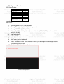
Gray Level:
1.
2.
Connect power, D-sub, into projector.
Change Timing and pattern of pattern generator:
3.
4.
Timing: 1024*768 @60Hz (XGA)
Pattern: As White-black pattern {A near white color (240,240,240) and a near black
color(16,16,16)}
5.
6.
7.
8.
Light on projector
Set user OSD values to default.
Enter factory mode.
Set Factory values to default.
9.
Press “Calibration RGB” to let the black level to just distinguish, and the light output
of white level to just max.
10. Check the 32 levels of gray. All steps must appear.
White-black pattern
72
4. YUV Alignment Procedure
OSD Default value:
Item
Cal R Offset
Cal G Offset
Cal B Offset
Cal R Gain
Cal G Gain
Cal B Gain
YPbPr R Offset
YPbPr B Offset
Procedure:
Value
127
127
127
127
127
127
127
127
1. Connect power, YpbPr cable (only G cable from DVD player) into projector.
2. Change Timing and play below Color-bar pattern from DVD player.
Timing: 480i
Pattern: Color-bar pattern
(since only G cable is connected, the projected image shows the color bar as black
and white)
3. Light on projector
4. Enter factory mode.
5. Press “Calibration YpbPr” to calibrate the mid level offset.
6. It’s completed.
Color-bar pattern
73
5.
Keystone Calibration
Condition:Horizontal plane(0∘)
1.
2.
3.
4.
5.
6.
Make projector be horizontal
Enter factory menu
Enter into Block
3
in factory menu
Select item “AutoKeystoneCal”
Press key Left or Right to do auto calibration
Finish 0∘calibration and bellow items will show data:
AutoKeystoneXCal: ≦ 5
AutoKeystoneXOffset: ≦ 20
74
Chapter 5
FRU List
Exploded Diagram
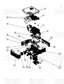
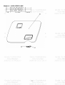
Module 1 – Total Exploded View
Note :
(item 9 ) There’s no Speaker in X1130.
(item 23 ) There’s no Zoom Ring in X1230S
75
76
Module 2 – ASSY UPPER CASE
77
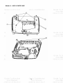
Module 3 – ASSY LOWER CASE
78
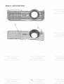
Module 4 – ASSY FRONT CASE
79
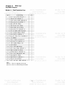
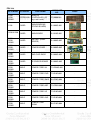
FRU List
Use in Model CATEGORY
PARTNAME
X1130/
X1230/
X1230S
REMOTE
ACCESSORY CONTROLLER (25
keys w/o Laser)
X1130
BOARD
ACER PART
NO.
Photo
VZ.J9000.001
MAIN BOARD(W/
KEYPAD BOARD)
55.J900Q.001
X1230/X1230
BOARD
S
MAIN BOARD
55.J910Q.001
X1130/
X1230/
X1230S
BOARD
BALLAST (LAMP
DRIVER)
55.J900Q.002
X1130/
X1230/
X1230S
BOARD
POWER BOARD
55.J900Q.003
BOARD
DMD CHIP BAOD
55.J900Q.004
BOARD
IR SENSOR BOARD
55.J900Q.005
CABLE
POWER CORD UK
27.LDW0Q.001
-
CABLE
POWER CORD EUR
27.LBJ0Q.001
-
CABLE
POWER CORD SWIS 50.LE20Q.004
-
CABLE
POWER CORD ARF
27.LCE0Q.002
-
CABLE
POWER CORD US
27.LBJ0Q.002
-
CABLE
POWER CORD AUS
27.LBJ0Q.004
-
CABLE
POWER CORD
CHINA
50.LE10Q.004
-
X1130/
X1230/
X1230S
X1130/
X1230/
X1230S
X1130/
X1230/
X1230S
X1130/
X1230/
X1230S
X1130/
X1230/
X1230S
X1130/
X1230/
X1230S
X1130/
X1230/
X1230S
X1130/
X1230/
X1230S
X1130/
X1230/
X1230S
80
X1130/
X1230/
X1230S
X1130/
X1230/
X1230S
X1130/
X1230/
X1230S
X1130/
X1230/
X1230S
X1130/
X1230/
X1230S
CABLE
POWER CORD
THAILAND
CABLE
POWER CORD INDIA 27.LCE0Q.001
-
CABLE
POWER CORD JP
27.LE20Q.001
-
CABLE
D-SUB CABLE
50.J900Q.001
-
CABLE
RCA CABLE
50.J900Q.002
-
X1130/
X1230/
X1230S
CABLE
CABLE M/B TO IR
BOARD
50.J900Q.003
X1130/
X1230/
X1230S
CABLE
CABLE BALLAST TO
50.J900Q.004
LAMP
X1130/
X1230/
X1230S
CABLE
CABLE POWER
50.J900Q.005
BOARD TO BALLAST
X1130/
X1230/
X1230S
CABLE
CABLE M/B TO
BALLAST
X1130
CASE/COVE
R/BRACKET REAR CASE
ASSEMBLY
60.J900Q.001
X1230/
X1230S
CASE/COVE
R/BRACKET REAR CASE
ASSEMBLY
60.J910Q.001
X1130/
X1230/
X1230S
CASE/COVE
R/BRACKET INLET CASE
ASSEMBLY
60.J900Q.002
X1130/
X1230/
X1230S
CASE/COVE
R/BRACKET OUTLET CASE
ASSEMBLY
60.J900Q.003
27.J900Q.001
50.J900Q.006
81
-
CASE/COVE UPPER CASE (W/
X1130/ X1230 R/BRACKET KEYPAD RUBBER&
ASSEMBLY BRACKET)
60.J900Q.004
X1230S
CASE/COVE UPPER CASE (W/
R/BRACKET KEYPAD RUBBER&
ASSEMBLY BRACKET)
60.J920Q.001
X1130/
X1230/
X1230S
CASE/COVE
LOWER CASE (W/
R/BRACKET
ADJUST FOOT)
ASSEMBLY
60.J900Q.005
CASE/COVE
FRONT CASE (W/O IR
60.J900Q.006
X1130/ X1230 R/BRACKET
BOARD)
ASSEMBLY
X1230S
CASE/COVE
FRONY CASE (W/O
R/BRACKET
IR BOARD)
ASSEMBLY
60.J920Q.002
X1130/
X1230/
X1230S
CASE/COVE
R/BRACKET LAMP DOOR
ASSEMBLY
60.J900Q.007
CASE/COVE
X1130/ X1230 R/BRACKET ZOOM RING
ASSEMBLY
60.J900Q.008
CASE/COVE
X1130/ X1230 R/BRACKET FOCUS RING
ASSEMBLY
60.J900Q.009
X1230S
CASE/COVE
R/BRACKET FOCUS RING
ASSEMBLY
60.J920Q.003
X1130/
X1230/
X1230S
DIGITAL
LIGHT
DEVICE
Phillips
X1130/X1230/X1230T EC.J9000.001
Lamp Module 189W
X1130/
X1230/
X1230S
DIGITAL
LIGHT
DEVICE
COLOR WHEEL
MODULE(W/
SENSOR BD &
CABLE)
82
57.J900Q.001
X1130/
X1230/
X1230S
DIGITAL
LIGHT
DEVICE
LIGHT PIPE
57.J900Q.002
DIGITAL
X1130/ X1230 LIGHT
DEVICE
LENS
57.J900Q.003
DIGITAL
LIGHT
DEVICE
LENS
57.J920Q.001
DMD CHIP
57.J900Q.004
DMD CHIP
57.J910Q.001
X1130
DIGITAL
LIGHT
DEVICE
ENGINE MODULE
57.J900Q.005
X1230/
X1230S
DIGITAL
LIGHT
DEVICE
ENGINE MODULE
57.J910Q.002
X1130/
X1230/
X1230S
FAN
FAN (X2)
23.J900Q.001
X1130/
X1230/
X1230S
FAN
FAN BLOWER
MODULE
23.J900Q.002
X1230/
X1230S
SPEAKER
SPEAKER
23.J910Q.001
X1130/
X1230/
X1230S
MISCELLANE
FOOT ADJFOOT
OUS
47.J900Q.001
X1130/
X1230/
X1230S
MISCELLANE RUBBER ADJFOOT
OUS
PAD
47.J900Q.002
X1230S
X1130
X1230/
X1230S
DIGITAL
LIGHT
DEVICE
DIGITAL
LIGHT
DEVICE
(Note) The updated P/N refers to latest Spare Part List
83
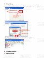
Appendix A - Code List: IR / RS232 / DDC Data
1. Remote Control Code:
IR setting value
Frequency: 38kHz
Protocal: NEC format
b. IR command code
Customer code:
:0813
84
2. RS-232 Command Code
General command type (Projector ‘receives’ commands)
No
Code (character)
Function feature
Note
1
OKOKOKOKOK
Power On
support
2
* 0 IR 001
Power On
support
3
* 0 IR 002
Power Off
support
4
* 0 IR 004
Keystone
support
5
* 0 IR 006
Mute
support
6
* 0 IR 007
Freeze
support
7
* 0 IR 008
Menu
support
8
* 0 IR 009
Up
support
9
* 0 IR 010
Down
support
10
* 0 IR 011
Right
support
11
* 0 IR 012
Left
support
12
* 0 IR 013
Enter
13
* 0 IR 014
Re-Sync
support
14
* 0 IR 015
Source Analog RGB for D-sub
support
15
* 0 IR 016
Source Digital RGB
16
* 0 IR 017
Source PbPr for D-sub
support
17
* 0 IR 018
Source S-Video
support
18
* 0 IR 019
Source Composite Video
support
19
* 0 IR 020
Source Component Video
support
20
* 0 IR 021
Aspect ratio 16:9
support
21
* 0 IR 022
Aspect ratio 4:3
support
22
* 0 IR 023
Volume +
support
23
* 0 IR 024
Volume –
support
24
* 0 IR 025
Brightness
support
25
* 0 IR 026
Contrast
support
26
* 0 IR 027
Color Temperature
support
27
* 0 IR 028
Source Analog RGB for DVI Port
Unsupport
28
* 0 IR 029
Source Analog YPbPr for DVI Port
Unsupport
29
* 0 IR 030
Hide
support
30
* 0 IR 031
Source
support
31
* 0 IR 032
Video: Color saturation adjustment
support
32
* 0 IR 033
Video: Hue adjustment
support
33
* 0 IR 034
Video: Sharpness adjustment
support
34
* 0 IR 035
Query Model name
support
35
* 0 IR 036
Query Native display resolution
support
36
* 0 IR 037
Query company name
support
37
* 0 IR 040
Aspect ratioL.Box
Unsupport
38
* 0 IR 041
Aspect ratio 1:1
Unsupport
39
* 0 IR 042
Keystone Up
support
40
* 0 IR 043
Keystone Down
support
Unsupport
Unsupport
85
41
* 0 IR 044
Keystone Left
Unsupport
42
* 0 IR 045
Keystone Right
Unsupport
43
* 0 IR 046
Zoom
support
44
* 0 IR 047
e-Key
support
45
* 0 IR 048
Color RGB
support
46
* 0 IR 049
Language
support
47
* 0 IR 050
Source HDMI
support
General command type (Projector ‘transmits’ commands)
NO
1
2
3
Code (character)
Function feature
Note
Model XXXXXXXX Return the Model name
Return the Native display
Res XXXXX
resolution
Name XXXXXXXX Return the company name
support
support
support
Lamp command type (Projector ‘receives’ commands)
NO
Code (character)
Function feature
Note
1
* 0 Lamp ?
Query the lamp ON/OFF
support
2
* 0 Lamp
Query the lamp hours
support
Lamp command type (Projector ‘transmits’ commands)
NO
Code (character)
Function feature
Note
1
Lamp 0
Return Lamp OFF status
support
2
Lamp 1
Return Lamp ON status
support
3
XXXX
Return Lamp hours
support
Source command type (Projector ‘receives’ commands)
NO
1
Code (character)
* 0 Src ?
Function feature
Note
Query source input type
support
86
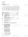
3. DDC Data:
X1130 EDID
:
EDID Block 0, Bytes 0-127 [00H-7FH]
Block Type: EDID 1.3
0
10
20
30
40
50
60
70
0
1
2
3
4
5
6
7
8
9
A B
C
D
E
F
________________________________________________________________
| 00 FF FF FF FF FF FF 00 04 72 05 90 01 00 00 00
| 01 12 01 03 0E 00 00 78 0A F4 46 A4 58 58 89 25
| 13 4F 5B BF EF 80 71 4A 81 80 81 40 90 40 A9 40
| 81 00 95 00 B3 00 A0 0F 20 00 31 58 1C 20 28 80
| 14 00 00 00 00 00 00 18 00 00 00 FD 00 30 56 1F
| 5C 11 00 0A 20 20 20 20 20 20 00 00 00 FC 00 58
| 31 31 33 30 0A 20 20 20 20 20 20 20 00 00 00 FF
| 00 4A 39 30 30 35 30 30 31 38 34 30 31 0A 00 6A
______________________________________________________________________
(08H-09H) ID Manufacturer Name _________________________
= ACR
(0AH-0BH) Product ID Code ______________________________
= 9005
(0CH-0FH) Last 5 Digits of Serial Number _______________
= 00001
(10H)
Week of Manufacture __________________________
= 01
(11H)
Year of Manufacture __________________________
= 2008
(12H)
EDID Version Number __________________________
=1
(13H)
EDID Revision Number _________________________
=3
(14H)
VIDEO INPUT DEFINITION:
Analog Signal
0.700, 0.300 (1.000 Vp-p)
Sync on Green, Composite Sync, Separate Syncs
(15H)
Maximum Horizontal Image Size ________________
=
mm
(16H)
Maximum Vertical Image Size __________________
=
mm
(17H)
Display Gamma ________________________________
= 2.20
(18H)
DPMS and Supported Feature(s):
Preferred Timing Mode
Display Type = R/G/B Color
(19H-22H) CHROMA INFO:
Red x - 0.644 Green x - 0.345 Blue x - 0.146 White x - 0.310
Red y - 0.347 Green y - 0.535 Blue y - 0.074 White y - 0.357
(23H)
ESTABLISHED TIMING I:
720 x 400 @ 70Hz (IBM,VGA)
640 x 480 @ 60Hz (IBM,VGA)
640 x 480 @ 67Hz (Apple,Mac II)
640 x 480 @ 72Hz (VESA)
640 x 480 @ 75Hz (VESA)
800 x 600 @ 56Hz (VESA)
800 x 600 @ 60Hz (VESA)
(24H)
ESTABLISHED TIMING II:
800 x 600 @ 72Hz (VESA)
800 x 600 @ 75Hz (VESA)
832 x 624 @ 75Hz (Apple,Mac II)
1024 x 768 @ 60Hz (VESA)
1024 x 768 @ 70Hz (VESA)
1024 x 768 @ 75Hz (VESA)
1280 x 1024 @ 75Hz (VESA)
(25H)
Manufacturer's Reserved Timing:
1152 x 870 @ 75Hz (Apple,Mac II)
(38-53)
Standard Timing Identification:
87
Standard Timing ID 1: 1152 x 864 @70Hz
Standard Timing ID 2: 1280 x 1024 @60Hz
Standard Timing ID 3: 1280 x 960 @60Hz
Standard Timing ID 4: 1400 x 1050 @60Hz
Standard Timing ID 5: 1600 x 1200 @60Hz
Standard Timing ID 6: 1280 x 800 @60Hz
Standard Timing ID 7: 1440 x 900 @60Hz
Standard Timing ID 8: 1680 x 1050 @60Hz
______________________________________________________________________
(36H-47H) Detailed Timing / Descriptor Block 1:
800x600 Pixel Clock: 40.00 MHz
______________________________________________________________________
Horizontal Image Size: 0 mm
Vertical Image Size: 0 mm
Refreshed Mode: Non-Interlaced
Normal Display - No Stereo
Horizontal:
Active Count: 800 pixels
Sync Offset: 40 pixels
Border: 0 pixels
Blanking Count: 256 pixels
Sync Pulse Width: 128 pixels
Frequency: 37.88 kHz
Vertical:
Active Count: 600 lines
Sync Offset: 1 lines
Border: 0 lines
Blanking Count: 28 lines
Sync Pulse Width: 4 lines
Frequency: 60.32 Hz
Digital Separate, Horizontal Polarity (-) Vertical Polarity (-)
______________________________________________________________________
(48H-59H) Detailed Timing / Descriptor Block 2:
Monitor Range Limits:
Min Vertical Freq - 48 Hz
Max Vertical Freq - 86 Hz
Min Horiz. Freq - 31 kHz
Max Horiz. Freq - 92 kHz
Pixel Clock - 170 MHz
GTF - Not Used
______________________________________________________________________
(5AH-6BH) Detailed Timing / Descriptor Block 3:
Monitor Name:
X1130
______________________________________________________________________
(6CH-7DH) Detailed Timing / Descriptor Block 4:
Monitor Serial Number:
J90050018401
(7EH) Block No: No Extension EDID Block(s)
CheckSum OK
88
X1230 EDID
:
EDID Block 0, Bytes 0-127 [00H-7FH]
Block Type: EDID 1.3
0
10
20
30
40
50
60
70
0
1
2
3
4
5
6
7
8
9
A
B
C
D
E
F
________________________________________________________________
| 00 FF FF FF FF FF FF 00 04 72 05 91 01 00 00 00
| 01 12 01 03 0E 00 00 78 0A F4 46 A4 58 58 89 25
| 13 4F 5B BF EE 80 71 4A 81 80 81 40 81 00 95 00
| 61 59 01 01 01 01 64 19 00 40 41 00 26 30 18 88
| 36 00 00 00 00 00 00 18 00 00 00 FD 00 30 56 1F
| 5D 0B 00 0A 20 20 20 20 20 20 00 00 00 FC 00 58
| 31 32 33 30 0A 20 20 20 20 20 20 20 00 00 00 FF
| 00 4A 39 31 30 35 30 30 31 38 34 30 31 0A 00 59
______________________________________________________________________
(08H-09H)
(0AH-0BH)
(0CH-0FH)
(10H)
(11H)
(12H)
(13H)
(14H)
(15H)
(16H)
(17H)
(18H)
ID Manufacturer Name _________________________
= ACR
Product ID Code ______________________________
= 9105
Last 5 Digits of Serial Number _______________
= 00001
Week of Manufacture __________________________
= 01
Year of Manufacture __________________________
= 2008
EDID Version Number __________________________
=1
EDID Revision Number _________________________
=3
VIDEO INPUT DEFINITION:
Analog Signal
0.700, 0.300 (1.000 Vp-p)
Sync on Green, Composite Sync, Separate Syncs
Maximum Horizontal Image Size ________________
=
Maximum Vertical Image Size __________________
=
Display Gamma ________________________________
DPMS and Supported Feature(s):
Preferred Timing Mode
Display Type = R/G/B Color
(19H-22H) CHROMA INFO:
Red x - 0.644 Green x - 0.345 Blue x - 0.146 White x - 0.310
Red y - 0.347 Green y - 0.535 Blue y - 0.074 White y - 0.357
(23H)
ESTABLISHED TIMING I:
720 x 400 @ 70Hz (IBM,VGA)
640 x 480 @ 60Hz (IBM,VGA)
640 x 480 @ 67Hz (Apple,Mac II)
640 x 480 @ 72Hz (VESA)
640 x 480 @ 75Hz (VESA)
800 x 600 @ 56Hz (VESA)
800 x 600 @ 60Hz (VESA)
(24H)
ESTABLISHED TIMING II:
800 x 600 @ 72Hz (VESA)
800 x 600 @ 75Hz (VESA)
832 x 624 @ 75Hz (Apple,Mac II)
1024 x 768 @ 60Hz (VESA)
1024 x 768 @ 70Hz (VESA)
1024 x 768 @ 75Hz (VESA)
(25H)
Manufacturer's Reserved Timing:
1152 x 870 @ 75Hz (Apple,Mac II)
(38-53)
Standard Timing Identification:
Standard Timing ID 1: 1152 x 864 @70Hz
Standard Timing ID 2: 1280 x 1024 @60Hz
89
mm
mm
= 2.20
Standard Timing ID 3: 1280 x 960 @60Hz
Standard Timing ID 4: 1280 x 800 @60Hz
Standard Timing ID 5: 1440 x 900 @60Hz
Standard Timing ID 6: 1024 x 768 @85Hz
Standard Timing ID 7 - Not Used
Standard Timing ID 8 - Not Used
______________________________________________________________________
(36H-47H) Detailed Timing / Descriptor Block 1:
1024x768 Pixel Clock: 65.00 MHz
______________________________________________________________________
Horizontal Image Size: 0 mm
Vertical Image Size: 0 mm
Refreshed Mode: Non-Interlaced
Normal Display - No Stereo
Horizontal:
Active Count: 1024 pixels
Sync Offset: 24 pixels
Border: 0 pixels
Blanking Count: 320 pixels
Sync Pulse Width: 136 pixels
Frequency: 48.36 kHz
Vertical:
Active Count: 768 lines
Sync Offset: 3 lines
Border: 0 lines
Blanking Count: 38 lines
Sync Pulse Width: 6 lines
Frequency: 60.00 Hz
Digital Separate, Horizontal Polarity (-) Vertical Polarity (-)
______________________________________________________________________
(48H-59H) Detailed Timing / Descriptor Block 2:
Monitor Range Limits:
Min Vertical Freq - 48 Hz
Max Vertical Freq - 86 Hz
Min Horiz. Freq - 31 kHz
Max Horiz. Freq - 93 kHz
Pixel Clock - 110 MHz
GTF - Not Used
______________________________________________________________________
(5AH-6BH) Detailed Timing / Descriptor Block 3:
Monitor Name:
X1230
______________________________________________________________________
(6CH-7DH) Detailed Timing / Descriptor Block 4:
Monitor Serial Number:
J91050018401
(7EH) Block No: No Extension EDID Block(s)
CheckSum OK
90
X1230S EDID
:
EDID Block 0, Bytes 0-127 [00H-7FH]
Block Type: EDID 1.3
0
10
20
30
40
50
60
70
0
1
2
3
4
5
6
7
8
9
A B
C
D
E
F
________________________________________________________________
| 00 FF FF FF FF FF FF 00 04 72 05 92 01 00 00 00
| 01 12 01 03 0E 00 00 78 0A F4 46 A3 58 58 88 24
| 13 50 59 BF EE 80 71 4A 81 80 81 40 81 00 95 00
| 61 59 01 01 01 01 64 19 00 40 41 00 26 30 18 88
| 36 00 00 00 00 00 00 18 00 00 00 FD 00 30 56 1F
| 5D 0B 00 0A 20 20 20 20 20 20 00 00 00 FC 00 58
| 31 32 33 30 53 0A 20 20 20 20 20 20 00 00 00 FF
| 00 4A 39 32 30 35 30 30 31 38 34 30 31 0A 00 0A
______________________________________________________________________
(08H-09H)
(0AH-0BH)
(0CH-0FH)
(10H)
(11H)
(12H)
(13H)
(14H)
(15H)
(16H)
(17H)
(18H)
ID Manufacturer Name _________________________
= ACR
Product ID Code ______________________________
= 9205
Last 5 Digits of Serial Number _______________
= 00001
Week of Manufacture __________________________
= 01
Year of Manufacture __________________________
= 2008
EDID Version Number __________________________
=1
EDID Revision Number _________________________
=3
VIDEO INPUT DEFINITION:
Analog Signal
0.700, 0.300 (1.000 Vp-p)
Sync on Green, Composite Sync, Separate Syncs
Maximum Horizontal Image Size ________________
=
Maximum Vertical Image Size __________________
=
Display Gamma ________________________________
DPMS and Supported Feature(s):
Preferred Timing Mode
Display Type = R/G/B Color
(19H-22H) CHROMA INFO:
Red x - 0.640 Green x - 0.345 Blue x - 0.142 White x - 0.313
Red y - 0.347 Green y - 0.531 Blue y - 0.074 White y - 0.350
(23H)
ESTABLISHED TIMING I:
720 x 400 @ 70Hz (IBM,VGA)
640 x 480 @ 60Hz (IBM,VGA)
640 x 480 @ 67Hz (Apple,Mac II)
640 x 480 @ 72Hz (VESA)
640 x 480 @ 75Hz (VESA)
800 x 600 @ 56Hz (VESA)
800 x 600 @ 60Hz (VESA)
(24H)
ESTABLISHED TIMING II:
800 x 600 @ 72Hz (VESA)
800 x 600 @ 75Hz (VESA)
832 x 624 @ 75Hz (Apple,Mac II)
1024 x 768 @ 60Hz (VESA)
1024 x 768 @ 70Hz (VESA)
1024 x 768 @ 75Hz (VESA)
(25H)
Manufacturer's Reserved Timing:
1152 x 870 @ 75Hz (Apple,Mac II)
(38-53)
Standard Timing Identification:
Standard Timing ID 1: 1152 x 864 @70Hz
Standard Timing ID 2: 1280 x 1024 @60Hz
91
mm
mm
= 2.20
Standard Timing ID 3: 1280 x 960 @60Hz
Standard Timing ID 4: 1280 x 800 @60Hz
Standard Timing ID 5: 1440 x 900 @60Hz
Standard Timing ID 6: 1024 x 768 @85Hz
Standard Timing ID 7 - Not Used
Standard Timing ID 8 - Not Used
______________________________________________________________________
(36H-47H) Detailed Timing / Descriptor Block 1:
1024x768 Pixel Clock: 65.00 MHz
______________________________________________________________________
Horizontal Image Size: 0 mm
Vertical Image Size: 0 mm
Refreshed Mode: Non-Interlaced
Normal Display - No Stereo
Horizontal:
Active Count: 1024 pixels
Sync Offset: 24 pixels
Border: 0 pixels
Blanking Count: 320 pixels
Sync Pulse Width: 136 pixels
Frequency: 48.36 kHz
Vertical:
Active Count: 768 lines
Sync Offset: 3 lines
Border: 0 lines
Blanking Count: 38 lines
Sync Pulse Width: 6 lines
Frequency: 60.00 Hz
Digital Separate, Horizontal Polarity (-) Vertical Polarity (-)
_____________________________________________________________________
(48H-59H) Detailed Timing / Descriptor Block 2:
Monitor Range Limits:
Min Vertical Freq - 48 Hz
Max Vertical Freq - 86 Hz
Min Horiz. Freq - 31 kHz
Max Horiz. Freq - 93 kHz
Pixel Clock - 110 MHz
GTF - Not Used
______________________________________________________________________
(5AH-6BH) Detailed Timing / Descriptor Block 3:
Monitor Name:
X1230S
______________________________________________________________________
(6CH-7DH) Detailed Timing / Descriptor Block 4:
Monitor Serial Number:
J92050018401
(7EH) Block No: No Extension EDID Block(s)
CheckSum OK
92
X1235 EDID
:
EDID Block 0, Bytes 0-127 [00H-7FH]
Block Type: EDID 1.3
0
10
20
30
40
50
60
70
0
1
2
3
4
5
6
7
8
9
A
B
C
D
E
F
________________________________________________________________
| 00 FF FF FF FF FF FF 00 04 72 05 97 01 00 00 00
| 01 12 01 03 0E 00 00 78 0A F4 46 A4 58 58 89 25
| 13 4F 5B BF EE 80 71 4A 81 80 81 40 81 00 95 00
| 61 59 01 01 01 01 64 19 00 40 41 00 26 30 18 88
| 36 00 00 00 00 00 00 18 00 00 00 FD 00 30 56 1F
| 5D 0B 00 0A 20 20 20 20 20 20 00 00 00 FC 00 58
| 31 32 33 35 0A 20 20 20 20 20 20 20 00 00 00 FF
| 00 4A 39 37 30 35 30 30 31 38 34 30 31 0A 00 48
______________________________________________________________________
(08H-09H)
(0AH-0BH)
(0CH-0FH)
(10H)
(11H)
(12H)
(13H)
(14H)
(15H)
(16H)
(17H)
(18H)
ID Manufacturer Name _________________________
= ACR
Product ID Code ______________________________
= 9705
Last 5 Digits of Serial Number _______________
= 00001
Week of Manufacture __________________________
= 01
Year of Manufacture __________________________
= 2008
EDID Version Number __________________________
=1
EDID Revision Number _________________________
=3
VIDEO INPUT DEFINITION:
Analog Signal
0.700, 0.300 (1.000 Vp-p)
Sync on Green, Composite Sync, Separate Syncs
Maximum Horizontal Image Size ________________
=
Maximum Vertical Image Size __________________
=
Display Gamma ________________________________
DPMS and Supported Feature(s):
Preferred Timing Mode
Display Type = R/G/B Color
(19H-22H) CHROMA INFO:
Red x - 0.644 Green x - 0.345 Blue x - 0.146 White x - 0.310
Red y - 0.347 Green y - 0.535 Blue y - 0.074 White y - 0.357
(23H)
ESTABLISHED TIMING I:
720 x 400 @ 70Hz (IBM,VGA)
640 x 480 @ 60Hz (IBM,VGA)
640 x 480 @ 67Hz (Apple,Mac II)
640 x 480 @ 72Hz (VESA)
640 x 480 @ 75Hz (VESA)
800 x 600 @ 56Hz (VESA)
800 x 600 @ 60Hz (VESA)
(24H)
ESTABLISHED TIMING II:
800 x 600 @ 72Hz (VESA)
800 x 600 @ 75Hz (VESA)
832 x 624 @ 75Hz (Apple,Mac II)
1024 x 768 @ 60Hz (VESA)
1024 x 768 @ 70Hz (VESA)
1024 x 768 @ 75Hz (VESA)
(25H)
Manufacturer's Reserved Timing:
1152 x 870 @ 75Hz (Apple,Mac II)
(38-53)
Standard Timing Identification:
Standard Timing ID 1: 1152 x 864 @70Hz
Standard Timing ID 2: 1280 x 1024 @60Hz
93
mm
mm
= 2.20
Standard Timing ID 3: 1280 x 960 @60Hz
Standard Timing ID 4: 1280 x 800 @60Hz
Standard Timing ID 5: 1440 x 900 @60Hz
Standard Timing ID 6: 1024 x 768 @85Hz
Standard Timing ID 7 - Not Used
Standard Timing ID 8 - Not Used
______________________________________________________________________
(36H-47H) Detailed Timing / Descriptor Block 1:
1024x768 Pixel Clock: 65.00 MHz
______________________________________________________________________
Horizontal Image Size: 0 mm
Vertical Image Size: 0 mm
Refreshed Mode: Non-Interlaced
Normal Display - No Stereo
Horizontal:
Active Count: 1024 pixels
Sync Offset: 24 pixels
Border: 0 pixels
Blanking Count: 320 pixels
Sync Pulse Width: 136 pixels
Frequency: 48.36 kHz
Vertical:
Active Count: 768 lines
Sync Offset: 3 lines
Border: 0 lines
Blanking Count: 38 lines
Sync Pulse Width: 6 lines
Frequency: 60.00 Hz
Digital Separate, Horizontal Polarity (-) Vertical Polarity (-)
______________________________________________________________________
(48H-59H) Detailed Timing / Descriptor Block 2:
Monitor Range Limits:
Min Vertical Freq - 48 Hz
Max Vertical Freq - 86 Hz
Min Horiz. Freq - 31 kHz
Max Horiz. Freq - 93 kHz
Pixel Clock - 110 MHz
GTF - Not Used
______________________________________________________________________
(5AH-6BH) Detailed Timing / Descriptor Block 3:
Monitor Name:
X1235
______________________________________________________________________
(6CH-7DH) Detailed Timing / Descriptor Block 4:
Monitor Serial Number:
J97050018401
(7EH) Block No: No Extension EDID Block(s)
CheckSum OK
94
X1230K EDID
:
EDID Block 0, Bytes 0-127 [00H-7FH]
Block Type: EDID 1.3
0
10
20
30
40
50
60
70
0
1
2
3
4
5
6
7
8
9
A
B
C
D
E
F
________________________________________________________________
| 00 FF FF FF FF FF FF 00 04 72 05 98 01 00 00 00
| 01 12 01 03 0E 00 00 78 0A F4 46 A4 58 58 89 25
| 13 4F 5B BF EE 80 71 4A 81 80 81 40 81 00 95 00
| 61 59 01 01 01 01 64 19 00 40 41 00 26 30 18 88
| 36 00 00 00 00 00 00 18 00 00 00 FD 00 30 56 1F
| 5D 0B 00 0A 20 20 20 20 20 20 00 00 00 FC 00 58
| 31 32 33 30 4B 0A 20 20 20 20 20 20 00 00 00 FF
| 00 4A 39 38 30 35 30 30 31 38 34 30 31 0A 00 20
______________________________________________________________________
(08H-09H)
(0AH-0BH)
(0CH-0FH)
(10H)
(11H)
(12H)
(13H)
(14H)
(15H)
(16H)
(17H)
(18H)
ID Manufacturer Name _________________________
= ACR
Product ID Code ______________________________
= 9805
Last 5 Digits of Serial Number _______________
= 00001
Week of Manufacture __________________________
= 01
Year of Manufacture __________________________
= 2008
EDID Version Number __________________________
=1
EDID Revision Number _________________________
=3
VIDEO INPUT DEFINITION:
Analog Signal
0.700, 0.300 (1.000 Vp-p)
Sync on Green, Composite Sync, Separate Syncs
Maximum Horizontal Image Size ________________
=
Maximum Vertical Image Size __________________
=
Display Gamma ________________________________
DPMS and Supported Feature(s):
Preferred Timing Mode
Display Type = R/G/B Color
(19H-22H) CHROMA INFO:
Red x - 0.644 Green x - 0.345 Blue x - 0.146 White x - 0.310
Red y - 0.347 Green y - 0.535 Blue y - 0.074 White y - 0.357
(23H)
ESTABLISHED TIMING I:
720 x 400 @ 70Hz (IBM,VGA)
640 x 480 @ 60Hz (IBM,VGA)
640 x 480 @ 67Hz (Apple,Mac II)
640 x 480 @ 72Hz (VESA)
640 x 480 @ 75Hz (VESA)
800 x 600 @ 56Hz (VESA)
800 x 600 @ 60Hz (VESA)
(24H)
ESTABLISHED TIMING II:
800 x 600 @ 72Hz (VESA)
800 x 600 @ 75Hz (VESA)
832 x 624 @ 75Hz (Apple,Mac II)
1024 x 768 @ 60Hz (VESA)
1024 x 768 @ 70Hz (VESA)
1024 x 768 @ 75Hz (VESA)
(25H)
Manufacturer's Reserved Timing:
1152 x 870 @ 75Hz (Apple,Mac II)
(38-53)
Standard Timing Identification:
Standard Timing ID 1: 1152 x 864 @70Hz
Standard Timing ID 2: 1280 x 1024 @60Hz
95
mm
mm
= 2.20
Standard Timing ID 3: 1280 x 960 @60Hz
Standard Timing ID 4: 1280 x 800 @60Hz
Standard Timing ID 5: 1440 x 900 @60Hz
Standard Timing ID 6: 1024 x 768 @85Hz
Standard Timing ID 7 - Not Used
Standard Timing ID 8 - Not Used
______________________________________________________________________
(36H-47H) Detailed Timing / Descriptor Block 1:
1024x768 Pixel Clock: 65.00 MHz
______________________________________________________________________
Horizontal Image Size: 0 mm
Vertical Image Size: 0 mm
Refreshed Mode: Non-Interlaced
Normal Display - No Stereo
Horizontal:
Active Count: 1024 pixels
Sync Offset: 24 pixels
Border: 0 pixels
Blanking Count: 320 pixels
Sync Pulse Width: 136 pixels
Frequency: 48.36 kHz
Vertical:
Active Count: 768 lines
Sync Offset: 3 lines
Border: 0 lines
Blanking Count: 38 lines
Sync Pulse Width: 6 lines
Frequency: 60.00 Hz
Digital Separate, Horizontal Polarity (-) Vertical Polarity (-)
______________________________________________________________________
(48H-59H) Detailed Timing / Descriptor Block 2:
Monitor Range Limits:
Min Vertical Freq - 48 Hz
Max Vertical Freq - 86 Hz
Min Horiz. Freq - 31 kHz
Max Horiz. Freq - 93 kHz
Pixel Clock - 110 MHz
GTF - Not Used
______________________________________________________________________
(5AH-6BH) Detailed Timing / Descriptor Block 3:
Monitor Name:
X1230K
______________________________________________________________________
(6CH-7DH) Detailed Timing / Descriptor Block 4:
Monitor Serial Number:
J98050018401
(7EH) Block No: No Extension EDID Block(s)
CheckSum OK
96