1
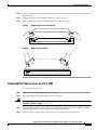
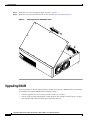
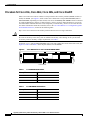
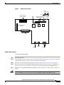
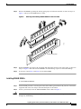
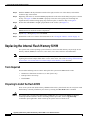
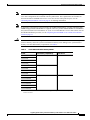
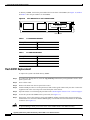
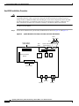
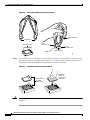
Upgrading System Memory, Internal Flash
Memory, and Boot ROM in Cisco 2600 Series
Routers
Product Numbers:
BOOT-2600=, BOOT-2600XM-256=, BOOT-2650=, MEM2600-4D=, MEM2600-8D=, MEM2600-16D=, MEM2600-32D=,
MEM2600XM-32D=, MEM2600XM-64D=, MEM2600XM-128D=, MEM2600XM-128DBOT=, MEM2600XM-2X64D=,
MEM2600-4FS=, MEM2600-8FS=, MEM2600-8U16FS=, MEM2600-16FS=, MEM2600XM-16FS=, MEM2600XM-32FS=,
MEM2620-32FSBOOT=, MEM2650-2X64D=, MEM2650-8D=, MEM2650-16D=, MEM2650-32D=, MEM2650-64D=,
MEM2650-8U32FS=, MEM2650-32FS=, MEM2691-64D=, MEM2691-128D=
Note
In this document, the term “Cisco 2600 series” represents the following router models: Cisco 2610,
Cisco 2610XM, Cisco 2611, Cisco 2611XM, Cisco 2612, Cisco 2613, Cisco 2620, Cisco 2620XM,
Cisco 2621, Cisco 2621XM, Cisco 2650, Cisco 2650XM, Cisco 2651, Cisco 2651XM, and Cisco 2691.
Use this document in conjunction with Cisco 2600 Series Hardware Installation Guide and the
Regulatory Compliance and Safety Information document for your router, both available online at
http://www.cisco.com/univercd/cc/td/doc/product/access/acs_mod/cis2600/index.htm.
If you have questions or need help, see the “Obtaining Documentation” section on page 21 and the
“Obtaining Technical Assistance” section on page 22 for further information.
This document includes the following sections:
•
Accessing the System Board, page 2
•
Upgrading DRAM, page 4
•
Replacing the Internal Flash Memory SIMM, page 12
•
Replacing the Boot ROM in Cisco 2600 Series Routers, page 15
•
Closing the Chassis, page 19
•
Obtaining Documentation, page 21
•
Documentation Feedback, page 21
•
Obtaining Technical Assistance, page 22
•
Obtaining Additional Publications and Information, page 23
Corporate Headquarters:
Cisco Systems, Inc., 170 West Tasman Drive, San Jose, CA 95134-1706 USA
Copyright © 2004 Cisco Systems, Inc. All rights reserved.
Accessing the System Board
Accessing the System Board
You must open the chassis to access the system board.
Note
To see translations of the various warnings that appear in this publication, refer to the Regulatory
Compliance and Safety Information document that accompanied this device.
Removing the Chassis Cover on Cisco 261x, Cisco 262x, Cisco 265x, and
Cisco 26xxXM
This section describes the procedure for opening the chassis by removing the chassis cover.
Warning
Do not touch the power supply when the power cord is connected. For systems with a power
switch, line voltages are present within the power supply even when the power switch is OFF and
the power cord is connected. For systems without a power switch, line voltages are present
within the power supply when the power cord is connected.
Warning
To prevent personal injury or damage to the chassis, never attempt to lift or tilt the chassis using the
handles on modules (such as power supplies, fans, or cards); these types of handles are not designed
to support the weight of the unit. Statement 1032
Tools Required
You need the following tools to remove and replace the chassis cover:
•
Number 2 Phillips screwdriver
•
Electrostatic discharge (ESD)-preventive wrist strap
Removing the Chassis Cover
To remove the chassis cover:
Step 1
Power off the router and unplug the AC power cord. If the router uses a DC power supply, remove power
from the DC circuit with the following steps:
a. Locate the circuit breaker on the panel board that services the DC circuit.
b. Switch the circuit breaker to the OFF position.
Step 2
Warning
Step 3
Disconnect all cables from the rear panel of the router.
Before opening the unit, disconnect the telephone-network cables to avoid contact with
telephone-network voltages. Statement 1041
Attach an ESD-preventive wrist strap and ensure that it makes good contact with your skin. Connect the
equipment end of the wrist strap to the metal back plate of the chassis.
Upgrading System Memory, Internal Flash Memory, and Boot ROM in Cisco 2600 Series Routers
2
OL-5474-01
Accessing the System Board
Step 4
Remove the screws located on the top of the chassis. Note that the chassis is composed of two sections:
top and bottom.
Step 5
Holding the chassis with both hands, position it as shown in Figure 1.
Step 6
Slide the top section away from the bottom section as shown in Figure 2.
Figure 1
Holding Chassis for Cover Removal
Figure 2
RPS
ACTIVITY
Removing Chassis Cover
RPS
SERIES
35392
Cisco 2600
POWER
SERIES
H11658
Cisco 2600
POWER
ACTIVITY
Removing the Chassis Cover on Cisco 2691
T o remove the chassis cover:
Step 1
Power off the router and unplug the AC power cord.
Step 2
Disconnect all network interface cables from the rear panel.
Warning
Before opening the unit, disconnect the telephone-network cables to avoid contact with
telephone-network voltages. Statement 1041
Step 3
Attach an ESD-preventive wrist strap and ensure that it makes good contact with your skin. Connect the
equipment end of the wrist strap to the metal back plate of the chassis.
Step 4
Place the router on a flat surface. Remove the five screws located on top of the cover.
Upgrading System Memory, Internal Flash Memory, and Boot ROM in Cisco 2600 Series Routers
OL-5474-01
3
Upgrading DRAM
Step 5
Rotate the cover up to a 45-degree angle. (See part 1, Figure 3.)
Step 6
Slide the cover to the side until the tabs are free from the slots. (See part 2, Figure 3.)
Figure 3
Removing the Cisco 2691 Router Cover
2
62482
1
Upgrading DRAM
This section describes how to upgrade dynamic random-access memory (DRAM) on the system board.
You might need to upgrade DRAM for the following reasons:
•
You have upgraded to a new Cisco IOS software feature set or release.
•
You are using very large routing tables or many protocols (for example, when the router is set up as
part of both a large external network and your internal network).
Upgrading System Memory, Internal Flash Memory, and Boot ROM in Cisco 2600 Series Routers
4
OL-5474-01
Upgrading DRAM
To see how much memory is currently installed in the router, enter the show version command. Near the
middle of the resulting output, a message similar to the following appears:
Cisco 2610(MPC860) processor (revision 0x200) with 28672K/4096K bytes of memory.
This line shows how much memory is installed (in this example, 28672Kb / 4096 Kb). The first number
represents primary memory and the second number represents shared memory.
Memory Capacities
Cisco 2600 series routers use two types of dynamic memory:
Caution
•
5-V EDO DRAM DIMMs (Cisco 2610, Cisco 2611, Cisco 2612, Cisco 2613, Cisco 2620, and
Cisco 2621 routers)
•
3.3-V SDRAM DIMMs (Cisco 26xxXM, Cisco 2650, Cisco 2651, and Cisco 2691 routers)
EDO DRAM and SDRAM DIMMs are not interchangeable. Although it is mechanically possible to
install an incorrect DRAM DIMM into a router, the router does not boot.
DRAM memory capacities are shown in Table 1:
Table 1
Cisco 2600 Series DRAM Memory Table
Router
DRAM Capacity
DRAM Type
Cisco 2610
EDO DRAM:
5-V
100-pin DIMM
Cisco 2611
32 MB, 64 MB
Cisco 2612
Cisco 2613
Cisco 2620
Cisco 2621
Cisco 2650
SDRAM:
Cisco 2651
32 MB, 64 MB, 96 MB, 128 MB
Cisco 2610XM
Cisco 2611XM
Cisco 2620XM
3.3-V
100-pin DIMM
SDRAM:
32 MB, 64 MB, 96 MB, 128 MB,
160 MB, 192 MB, 256 MB
Cisco 2621XM
Cisco 2650XM
Cisco 2651XM
Cisco 2691
SDRAM:
64 MB, 128 MB, 192 MB, 256 MB
3.3-V
168-pin DIMM
Upgrading System Memory, Internal Flash Memory, and Boot ROM in Cisco 2600 Series Routers
OL-5474-01
5
Upgrading DRAM
Procedure for Cisco 261x, Cisco 262x, Cisco 265x, and Cisco 26xxXM
Most Cisco 2600 series routers contain two 100-pin dual in-line memory module (DIMM) sockets (or
banks) for DRAM. (See Figure 5.) Each socket can be filled with a 100-pin DRAM DIMM (EDO or
SDRAM DIMMs, depending on router model). You can use the memory-size iomem software command
to configure DRAM as a mixture of shared memory, which is used for data transmitted or received by
network modules and WAN interface cards, and primary or main memory, which is reserved for the CPU.
For further information about this command, refer to the Cisco IOS Release 12.3 configuration guides
and command references, located at the following URL:
http://www.cisco.com/univercd/cc/td/doc/product/software/ios123/123cgcr/index.htm
Caution
It is critical that the correct voltage DRAM modules be installed in Cisco 2600 series routers. Using
the incorrect memory causes the system to malfunction and may cause damage to the system board
or memory card. For memory voltage requirements, see Table 1.
To identify a 3.3-V 100-pin SDRAM DIMM, look for the part number label on the front of the card. (See
Figure 4.) Table 2 and Table 3 show the part numbers for the DIMMs.
Figure 4
Cisco 2600 Series 3.3- and 5-V 100-Pin DRAM DIMM
72185
15-4108-01
Part number
Table 2
3.3-V SDRAM Part Numbers
Memory Size
3.3-V SDRAM
32 MB
15-4108-xx
64 MB
15-4508-xx
128 MB
15-8693-xx
Table 3
5-V EDO DRAM Part Numbers
Memory Size
5-V EDO DRAM
8 MB
15-2854-xx
16 MB
15-2853-xx
32 MB
15-2851-xx
Upgrading System Memory, Internal Flash Memory, and Boot ROM in Cisco 2600 Series Routers
6
OL-5474-01
Upgrading DRAM
Figure 5
DIMM Socket Location
Duart
reset Reset
Pin 1
Primary memory
(DRAM DIMMs)
Advanced Interface
Module
Boot
ROM
System-code SIMM
(Flash memory)
Lattice
U22
U23
56421
PCI connector
Ethernet
Ethernet
AUX
Console
DRAM DIMM Installation
To install the DRAM DIMMs:
Step 1
Power off the router.
Step 2
Attach an ESD-preventive wrist strap and ensure that it makes good contact with your skin. Connect the
equipment end of the wrist strap to the metal back plate of the chassis.
Step 3
Open the cover following the instructions in the “Removing the Chassis Cover” section on page 2.
Step 4
Begin removing the existing DRAM DIMM by pulling outward on the connectors to unlatch them, as
shown in Step 1 of part A in Figure 6. Be careful not to break the holders on the DIMM connector.
Step 5
Remove the existing DRAM DIMM by pulling the module straight up, as shown in Step 2 of part A in
Figure 6.
Caution
To prevent damage, do not press on the center of the DIMMs. Handle each DIMM carefully.
Upgrading System Memory, Internal Flash Memory, and Boot ROM in Cisco 2600 Series Routers
OL-5474-01
7
Upgrading DRAM
Step 6
Note
Position the new DIMM so that the polarization notch is located at the left end of the DIMM socket as
shown in Figure 6.
Make sure that the new DIMM is the correct type, EDO or SDRAM, for your router. (See Table 1.)
Figure 6
Removing and Replacing the 100-Pin DRAM DIMM
1
2
A
1
4
3
B
72277
3
Step 7
Insert the new DRAM DIMM by sliding the end with the metal fingers into the DIMM connector socket
at an angle of approximately 90 degrees to the system card. Gently rock the DIMM back into place until
the latch on either side snaps into place. See Step 3 and Step 4 of part B in Figure 6. Do not use excessive
force, because the connector might break.
Step 8
Reinstall the router cover. Follow the instructions in the “Closing the Chassis” section on page 19.
Upgrading System Memory, Internal Flash Memory, and Boot ROM in Cisco 2600 Series Routers
8
OL-5474-01
Upgrading DRAM
Procedure for Cisco 2691
This section describes how to upgrade synchronous dynamic random access memory (SDRAM) dual
in-line memory modules (DIMMs) in Cisco 2691 routers.
The Cisco 2691 router contains two 168-pin DIMM sockets for SDRAM. Each socket can be filled with
a single 64-bit-wide, 168-pin SDRAM DIMM; however, if you install only one DIMM, you must install
it in slot 0.
You can configure SDRAM as a mixture of main memory, which is reserved for the CPU, and shared
memory, which is used for data transmitted or received by modules and WAN interface cards. See
Figure 7 for DIMM locations.
To see how much memory is currently installed in the router, enter the show version command while the
router is in privileged EXEC mode (Router#). Near the middle of the resulting output, a message similar
to the following appears:
cisco 2691 (R7000) processor (revision 0.5) with 121856K/9216K bytes of memory.
This line shows how much memory is installed (in this example, 121856 Kb / 9216 Kb). The first number
represents primary memory, and the second number represents shared memory. Your router supports up
to 256 MB of SDRAM.
Note
To use a 64-bit mode SDRAM configuration, the memory size of the DIMM in slot 1 must be less
than or equal to the memory size of the DIMM in slot 0.
Figure 7
SDRAM DIMM Locations in the Cisco 2691 Router
SDRAM DIMMs
Slot 0
72012
Slot 1
Upgrading System Memory, Internal Flash Memory, and Boot ROM in Cisco 2600 Series Routers
OL-5474-01
9
Upgrading DRAM
Table 4
SDRAM Configurations for Cisco 2691 Routers
DIMM 0
DIMM 1
Total
64 MB DIMM
—
64 MB
128 MB DIMM
—
128 MB
64 MB DIMM
64 MB DIMM
128 MB
—
128 MB DIMM
128 MB
64 MB DIMM
128 MB DIMM
192 MB
128 MB DIMM
64 MB DIMM
192 MB
128 MB DIMM
128 MB DIMM
256 MB
SDRAM DIMM Orientation
DIMMs are manufactured with polarization notches to ensure proper orientation, and alignment holes to
ensure proper positioning. Figure 8 shows the polarization notches and alignment holes on a DIMM.
Caution
To avoid damaging ESD-sensitive components, observe all ESD precautions. To avoid damaging the
system board, do not use excessive force when you remove or replace DIMMs.
168-Pin SDRAM DIMM
17338
Figure 8
Connector edge
Polarization notches
Alignment holes
Removing SDRAM DIMMS
To remove SDRAM DIMMs:
Step 1
Attach an ESD-preventive wrist strap and ensure that it makes good contact with your skin. Connect the
equipment end of the wrist strap to the metal back plate of the chassis.
Step 2
On the system board, locate the SDRAM DIMM sockets shown in Figure 7.
Caution
Handle DIMMs by the edges only. DIMMs are ESD-sensitive components and can be damaged by
mishandling.
Upgrading System Memory, Internal Flash Memory, and Boot ROM in Cisco 2600 Series Routers
10
OL-5474-01
Upgrading DRAM
Step 3
Remove the DIMM by pushing the locking spring clips on both sides outward, as shown in Step 2 of
Figure 9. This ejects the DIMM from its socket.
Figure 9
Removing and Installing SDRAM DIMMs on the Cisco 2691
2
1
17943
2
Locking spring clips
Step 4
Hold the DIMM by the edges with your thumb and index finger and lift it out of the socket, as shown in
Step 1 of Figure 9. Place the removed DIMM in an antistatic bag to protect it from ESD damage.
Step 5
If necessary, repeat Step 3 and Step 4 for the other DIMM.
Installing SDRAM DIMMs
To install SDRAM DIMMs:
Step 1
Attach an ESD-preventive wrist strap and ensure that it makes good contact with your skin. Connect the
equipment end of the wrist strap to the metal back plate of the chassis.
Step 2
On the system board, locate the SDRAM DIMM sockets shown in Figure 7.
Caution
Handle DIMMs by the nonconnector edges only. DIMMs are ESD-sensitive components and can be
damaged by mishandling.
Upgrading System Memory, Internal Flash Memory, and Boot ROM in Cisco 2600 Series Routers
OL-5474-01
11
Replacing the Internal Flash Memory SIMM
Step 3
Hold the DIMM with the polarization notch on the right, near the rear of the chassis, and with the
connector edge at the bottom.
Step 4
Beginning with socket 0, insert the DIMM perpendicular to the socket. Push firmly into place, as shown
in Step 1 of Figure 9. When the DIMM is properly seated, the socket guide posts fit through the
alignment holes, and the locking spring clips click into place, as shown in Step 2 of Figure 9.
Step 5
Ensure that each DIMM is straight (perpendicular to the socket). (See Figure 9.)
Caution
It is normal to feel some resistance when installing a DIMM, but do not use excessive force on the
DIMM, and do not touch the surface components.
Step 6
Repeat Step 3 through Step 5 for each DIMM.
Step 7
Reinstall the router cover. Follow the instructions in the “Closing the Chassis” section on page 19.
Replacing the Internal Flash Memory SIMM
The system code (router operating system software) is stored in a flash memory 80-pin single in-line
memory module (SIMM) in Cisco 261x, Cisco 262x, Cisco 265x, and Cisco 26xxXM routers.
Note
In Cisco 2691 routers, the internal flash memory is a compact flash card, not a SIMM. If you are
replacing the internal compact flash card in a Cisco 2691 router, refer to the Installing and Formatting
ICisco I2691, Cisco I3631 and Cisco I3700 Compact Flash Memory Cards document.
Tools Required
You need the following tools to remove and replace the system-code SIMM on the router:
•
Medium-size flat-blade screwdriver (1/4-inch [0.625 cm])
•
ESD-preventive wrist strap
•
Flash SIMM
Preparing to Install the Flash SIMM
There is one system-code (flash memory) SIMM socket on the system board. You can verify how much
flash memory is already installed in your router by entering the show flash EXEC command.
Caution
The system code is stored on the flash memory SIMM, but new system-code SIMMs are shipped
without preinstalled software. Before continuing with this procedure, use the copy flash tftp
command in privileged EXEC mode to back up the system code to a TFTP server.
Upgrading System Memory, Internal Flash Memory, and Boot ROM in Cisco 2600 Series Routers
12
OL-5474-01
Replacing the Internal Flash Memory SIMM
Note
For more information about the copy flash tftp command and other related commands, refer to the
Cisco IOS configuration and command reference publications. These publications are available on
the Documentation CD-ROM and on Cisco.com. You can also order printed copies. See the
“Obtaining Documentation” section on page 21 for ordering information.
Note
To upgrade a Cisco 2620 or Cisco 2621 router to 32 MB of flash memory, you must install the flash
SIMM and upgraded boot ROM that are supplied with Cisco product number MEM2620-32FSBOOT=,
and you must install Cisco IOS Release 12.1(3)T or Cisco IOS Release 12.2T or later release. For the
boot ROM installation procedure, see the “Replacing the Boot ROM in Cisco 2600 Series Routers”
section on page 15.
Caution
It is critical that the correct voltage SIMMs be installed in the Cisco 2600 series routers. Using the
incorrect memory causes the system to malfunction and may cause damage to the system board or
memory card. For flash memory requirements, see Table 5.
Table 5
Cisco 2600 Series Flash Memory SIMMs
Router
Flash Memory Compatibility
Flash Device
Cisco 2610
8 MB, 16 MB
5-V SIMM
Cisco 2611
Cisco 2612
Cisco 2613
Cisco 26201
Cisco 2621
8 MB, 16 MB, 24 MB, 32 MB
1
Cisco 2650
Cisco 2651
Cisco 2610XM
16 MB, 32 MB, 48 MB
3.3-V SIMM
Cisco 2611XM
Cisco 2620XM
Cisco 2621XM
Cisco 2650XM
Cisco 2651XM
1. For Cisco 2620 and Cisco 2621 routers, a boot ROM upgrade is required for 32 MB flash operation.
See the note above.
Upgrading System Memory, Internal Flash Memory, and Boot ROM in Cisco 2600 Series Routers
OL-5474-01
13
Replacing the Internal Flash Memory SIMM
To identify a SIMM, look for the part number label on the front of the SIMM. (See Figure 10.) Table 6
and Table 7 show the part numbers for the SIMMs.
Figure 10
Cisco 2600 Series 3.3- and 5-V 80-Pin SIMM
72187
16-2462-02
Part number
Table 6
3.3-V SIMM Part Numbers
Memory Size
3.3-V SIMMs
16 MB
16-2462-xx
32 MB
16-2346-xx
Table 7
5-V SIMM Part Numbers
Memory Size
5-V SIMMs
8 MB
16-0965-xx
16 MB
16-1378-xx
32 MB
16-1745-xx
Flash SIMM Replacement
To replace the system-code flash memory SIMM:
Step 1
If you have not already done so, enter the copy flash tftp command in privileged EXEC mode to back
up the system code.
Step 2
Power off the router.
Step 3
Remove all cables from the rear panel of the router.
Step 4
Attach an ESD-preventive wrist strap and ensure that it makes good contact with your skin. Connect the
equipment end of the wrist strap to the metal back plate of the chassis.
Step 5
Open the chassis cover following the procedure in the “Removing the Chassis Cover” section on page 2.
Step 6
Locate the system-code SIMM on the system card. (See Figure 11.)
Step 7
If necessary, remove the existing system-code SIMM by pulling outward on the connector holders to
unlatch them. The connector holds the SIMM tightly, so be careful not to break the holders on the SIMM
connector. (See Figure 11.)
Caution
To prevent damage, do not press on the center of the SIMM. Handle each SIMM carefully.
Upgrading System Memory, Internal Flash Memory, and Boot ROM in Cisco 2600 Series Routers
14
OL-5474-01
Replacing the Boot ROM in Cisco 2600 Series Routers
Figure 11
Removing and Replacing the System-Code SIMM
Tab
SIMM
Tab
10244
SIMM connector
(on motherboard)
Step 8
Position the new SIMM so that the polarization notch is located at the left end of the SIMM socket.
Caution
To prevent damage, note that some flash memory SIMMs have the components mounted on the rear
side; therefore, when inserting the SIMM, always use the polarization notch as a reference and not
the position of the components on the SIMM.
Step 9
Insert the new SIMM by sliding the end with the metal fingers into the SIMM connector socket at
approximately a 90º angle to the system card. Gently rock the SIMM back into place until the latches on
both sides snap into place. Do not use excessive force, because the connector might break.
Step 10
Replace the router cover following the procedure in the “Closing the Chassis” section on page 19.
Replacing the Boot ROM in Cisco 2600 Series Routers
This section describes the procedure for replacing the boot ROM in Cisco 261x, Cisco 262x, Cisco 265x,
and Cisco 26xxXM routers.
Note
The boot ROM in Cisco 2691 routers is not field replaceable. The ROM monitor in a Cisco 2691 router
can be upgraded by downloading a ROM monitor image. Refer to the online document ROM Monitor
Download Procedures for Cisco 2691, Cisco, 3631, Cisco 3725, and Cisco 3745 Routers.
Upgrading System Memory, Internal Flash Memory, and Boot ROM in Cisco 2600 Series Routers
OL-5474-01
15
Replacing the Boot ROM in Cisco 2600 Series Routers
Boot ROM Installation Procedure
Caution
Correct placement of the boot ROM is crucial. If improperly positioned, the new component could
be damaged when the router is powered on. Read all instructions before proceeding. To prevent
damage to the boot ROM from ESD (when handling the router and its components), follow the ESD
procedures described in your hardware guide and see the appropriate regulatory compliance and
safety information document. Be careful not to damage or scratch the printed circuit board.
To replace the boot ROM:
Step 1
Locate the boot ROM on the system board (motherboard) as shown in Figure 12 and Figure 13.
Figure 12
System Board for Cisco 261x, Cisco 262x, and Cisco 265x Routers
Duart
reset Reset
Pin 1
Primary memory
(DRAM DIMMs)
Advanced Interface
Module
Boot
ROM
System-code SIMM
(Flash memory)
Lattice
U22
U23
56421
PCI connector
Ethernet
Ethernet
AUX
Console
Upgrading System Memory, Internal Flash Memory, and Boot ROM in Cisco 2600 Series Routers
16
OL-5474-01
Replacing the Boot ROM in Cisco 2600 Series Routers
Figure 13
System Card Layout for Cisco 26xxXM Routers
Duart
reset Reset
Pin 1
Primary memory
(DRAM DIMMs)
Advanced Interface
Module
Boot
ROM
System-code SIMM
(Flash memory)
Lattice
U24
U25
72279
PCI connector
Ethernet
Ethernet
Step 2
AUX
Console
Gently remove the old ROM with a ROM extraction tool or a small flat-blade screwdriver. (See
Figure 14.)
Upgrading System Memory, Internal Flash Memory, and Boot ROM in Cisco 2600 Series Routers
OL-5474-01
17
Replacing the Boot ROM in Cisco 2600 Series Routers
Figure 14
Removing the ROM from the System Board
PLCC extraction
tool
Angled tips
Extraction slots
PLCC
extraction slot
PLCC
extraction slot
ROM socket
14624
ROM
Step 3
Orient and insert the new ROM in its socket as shown in Figure 15, being careful to not bend or crush
any of the bottom pins. To straighten out a bent pin, use needlenose pliers. Align the notch in the new
ROM with the notch in the ROM socket, ignoring the orientation of the label.
Figure 15
Installing the ROM in the System Board
14063
Align notches
on ROM
and socket
Press the
ROM into
place evenly
and firmly
Caution
The notch on the ROM must match the notch on the socket on the card. Installing the ROM backward
damages it.
Upgrading System Memory, Internal Flash Memory, and Boot ROM in Cisco 2600 Series Routers
18
OL-5474-01
Closing the Chassis
Testing ROM Installation
Tip
Before testing your ROM installation, close the router chassis using the procedure provided in the
“Closing the Chassis” section on page 19.
Test your installation by rebooting the router. If you installed the ROM correctly, the router boots into
the ROM monitor or operating system.
If you suspect that the ROM is inserted incorrectly, remove and reinstall the ROM as described in the
“Replacing the Boot ROM in Cisco 2600 Series Routers” section on page 15. Reboot the router again.
Closing the Chassis
This section describes the procedure for closing the chassis.
Installing the Chassis Cover on Cisco 261x, Cisco 262x, Cisco 265x, and
Cisco 26xxXM
To close the chassis:
Step 1
Caution
Referring to Figure 1 and Figure 2, press the two chassis sections together and verify the following:
•
The top section fits into the rear of the bottom section. The bottom section fits into the front of the
top section.
•
Each side of the top and bottom sections fits together.
To fit the two sections together, it might be necessary to work them together at one end and then the
other, working back and forth; however, use care to prevent bending the chassis edges.
Step 2
When the two sections fit together snugly, slide the chassis top so it fits into the front bezel.
Step 3
Replace the cover screws. Tighten the screws to no more than 8 or 9 inch/pound of torque.
Step 4
Reinstall the chassis on the wall, rack, desktop, or table.
Step 5
Reconnect all cables. If the router uses a DC power supply, switch the circuit breaker to the ON position.
Installing the Chassis Cover on Cisco 2691
Step 1
Hold the cover so the tabs at the rear of the cover are aligned with the chassis.
Step 2
Push the cover toward the rear, making sure that the cover tabs fit under the chassis back panel, and the
back panel tabs fit under the cover.
Step 3
Slide the cover slightly to the left to lock the cover into position. (See part 1 in Figure 16.)
Upgrading System Memory, Internal Flash Memory, and Boot ROM in Cisco 2600 Series Routers
OL-5474-01
19
Closing the Chassis
Figure 16
Replacing the Cisco 2691 Router Cover
1
62490
2
Step 4
Lower the front of the cover onto the chassis. (See part 2 in Figure 16.)
Step 5
Fasten the cover with the five screws you set aside earlier.
Step 6
Reinstall the chassis on the wall, rack, desktop, or table.
Step 7
Reconnect all cables.
Upgrading System Memory, Internal Flash Memory, and Boot ROM in Cisco 2600 Series Routers
20
OL-5474-01
Obtaining Documentation
Obtaining Documentation
Cisco documentation and additional literature are available on Cisco.com. Cisco also provides several
ways to obtain technical assistance and other technical resources. These sections explain how to obtain
technical information from Cisco Systems.
Cisco.com
You can access the most current Cisco documentation on the World Wide Web at this URL:
http://www.cisco.com/univercd/home/home.htm
You can access the Cisco website at this URL:
http://www.cisco.com
International Cisco websites can be accessed from this URL:
http://www.cisco.com/public/countries_languages.shtml
Ordering Documentation
You can find instructions for ordering documentation at this URL:
http://www.cisco.com/univercd/cc/td/doc/es_inpck/pdi.htm
You can order Cisco documentation in these ways:
•
Registered Cisco.com users (Cisco direct customers) can order Cisco product documentation from
the Ordering tool:
http://www.cisco.com/en/US/partner/ordering/index.shtml
•
Nonregistered Cisco.com users can order documentation through a local account representative by
calling Cisco Systems Corporate Headquarters (California, USA) at 408 526-7208 or, elsewhere in
North America, by calling 800 553-NETS (6387).
Documentation Feedback
You can submit e-mail comments about technical documentation to [email protected].
You can submit comments by using the response card (if present) behind the front cover of your
document or by writing to the following address:
Cisco Systems
Attn: Customer Document Ordering
170 West Tasman Drive
San Jose, CA 95134-9883
We appreciate your comments.
Upgrading System Memory, Internal Flash Memory, and Boot ROM in Cisco 2600 Series Routers
OL-5474-01
21
Obtaining Technical Assistance
Obtaining Technical Assistance
For all customers, partners, resellers, and distributors who hold valid Cisco service contracts, the Cisco
Technical Assistance Center (TAC) provides 24-hour-a-day, award-winning technical support services,
online and over the phone. Cisco.com features the Cisco TAC website as an online starting point for
technical assistance. If you do not hold a valid Cisco service contract, please contact your reseller.
Cisco TAC Website
The Cisco TAC website provides online documents and tools for troubleshooting and resolving technical
issues with Cisco products and technologies. The Cisco TAC website is available 24 hours a day, 365
days a year. The Cisco TAC website is located at this URL:
http://www.cisco.com/tac
Accessing all the tools on the Cisco TAC website requires a Cisco.com user ID and password. If you
have a valid service contract but do not have a login ID or password, register at this URL:
http://tools.cisco.com/RPF/register/register.do
Opening a TAC Case
Using the online TAC Case Open Tool is the fastest way to open P3 and P4 cases. (P3 and P4 cases are
those in which your network is minimally impaired or for which you require product information.) After
you describe your situation, the TAC Case Open Tool automatically recommends resources for an
immediate solution. If your issue is not resolved using the recommended resources, your case will be
assigned to a Cisco TAC engineer. The online TAC Case Open Tool is located at this URL:
http://www.cisco.com/tac/caseopen
For P1 or P2 cases (P1 and P2 cases are those in which your production network is down or severely
degraded) or if you do not have Internet access, contact Cisco TAC by telephone. Cisco TAC engineers
are assigned immediately to P1 and P2 cases to help keep your business operations running smoothly.
To open a case by telephone, use one of the following numbers:
Asia-Pacific: +61 2 8446 7411 (Australia: 1 800 805 227)
EMEA: +32 2 704 55 55
USA: 1 800 553-2447
For a complete listing of Cisco TAC contacts, go to this URL:
http://www.cisco.com/warp/public/687/Directory/DirTAC.shtml
TAC Case Priority Definitions
To ensure that all cases are reported in a standard format, Cisco has established case priority definitions.
Priority 1 (P1)—Your network is “down” or there is a critical impact to your business operations. You
and Cisco will commit all necessary resources around the clock to resolve the situation.
Priority 2 (P2)—Operation of an existing network is severely degraded, or significant aspects of your
business operation are negatively affected by inadequate performance of Cisco products. You and Cisco
will commit full-time resources during normal business hours to resolve the situation.
Upgrading System Memory, Internal Flash Memory, and Boot ROM in Cisco 2600 Series Routers
22
OL-5474-01
Obtaining Additional Publications and Information
Priority 3 (P3)—Operational performance of your network is impaired, but most business operations
remain functional. You and Cisco will commit resources during normal business hours to restore service
to satisfactory levels.
Priority 4 (P4)—You require information or assistance with Cisco product capabilities, installation, or
configuration. There is little or no effect on your business operations.
Obtaining Additional Publications and Information
Information about Cisco products, technologies, and network solutions is available from various online
and printed sources.
•
Cisco Marketplace provides a variety of Cisco books, reference guides, and logo merchandise. Go
to this URL to visit the company store:
http://www.cisco.com/go/marketplace/
•
The Cisco Product Catalog describes the networking products offered by Cisco Systems, as well as
ordering and customer support services. Access the Cisco Product Catalog at this URL:
http://cisco.com/univercd/cc/td/doc/pcat/
•
Cisco Press publishes a wide range of general networking, training and certification titles. Both new
and experienced users will benefit from these publications. For current Cisco Press titles and other
information, go to Cisco Press online at this URL:
http://www.ciscopress.com
•
Packet magazine is the Cisco quarterly publication that provides the latest networking trends,
technology breakthroughs, and Cisco products and solutions to help industry professionals get the
most from their networking investment. Included are networking deployment and troubleshooting
tips, configuration examples, customer case studies, tutorials and training, certification information,
and links to numerous in-depth online resources. You can access Packet magazine at this URL:
http://www.cisco.com/packet
•
iQ Magazine is the Cisco bimonthly publication that delivers the latest information about Internet
business strategies for executives. You can access iQ Magazine at this URL:
http://www.cisco.com/go/iqmagazine
•
Internet Protocol Journal is a quarterly journal published by Cisco Systems for engineering
professionals involved in designing, developing, and operating public and private internets and
intranets. You can access the Internet Protocol Journal at this URL:
http://www.cisco.com/ipj
•
Training—Cisco offers world-class networking training. Current offerings in network training are
listed at this URL:
http://www.cisco.com/en/US/learning/index.html
Upgrading System Memory, Internal Flash Memory, and Boot ROM in Cisco 2600 Series Routers
OL-5474-01
23
Obtaining Additional Publications and Information
This document is to be used in conjunction with Cisco 2600 Series Hardware Installation Guide and the Regulatory Compliance and Safety
Information document for your router.
CCIP, CCSP, the Cisco Arrow logo, the Cisco Powered Network mark, Cisco Unity, Follow Me Browsing, FormShare, and StackWise are
trademarks of Cisco Systems, Inc.; Changing the Way We Work, Live, Play, and Learn, and iQuick Study are service marks of Cisco Systems, Inc.;
and Aironet, ASIST, BPX, Catalyst, CCDA, CCDP, CCIE, CCNA, CCNP, Cisco, the Cisco Certified Internetwork Expert logo, Cisco IOS, the Cisco
IOS logo, Cisco Press, Cisco Systems, Cisco Systems Capital, the Cisco Systems logo, Empowering the Internet Generation, Enterprise/Solver,
EtherChannel, EtherSwitch, Fast Step, GigaStack, Internet Quotient, IOS, IP/TV, iQ Expertise, the iQ logo, iQ Net Readiness Scorecard,
LightStream, MGX, MICA, the Networkers logo, Networking Academy, Network Registrar, Packet, PIX, Post-Routing, Pre-Routing, RateMUX,
Registrar, ScriptShare, SlideCast, SMARTnet, StrataView Plus, Stratm, SwitchProbe, TeleRouter, The Fastest Way to Increase Your Internet
Quotient, TransPath, and VCO are registered trademarks of Cisco Systems, Inc. and/or its affiliates in the United States and certain other countries.
All other trademarks mentioned in this document or Website are the property of their respective owners. The use of the word partner does not imply
a partnership relationship between Cisco and any other company. (0401R)
Copyright © 2002-2004, Cisco Systems, Inc.
All rights reserved.
Upgrading System Memory, Internal Flash Memory, and Boot ROM in Cisco 2600 Series Routers
24
OL-5474-01