1
Using
Your
Appliance
BotzWare
2.5
Edition
®
Preface
Copyright
© Copyright NetBotz Inc. 2000 - 2005
Trademarks
BotzWare, NetBotz, and the NetBotz symbol are registered trademarks of NetBotz, Inc.
Other brand and product names are registered trademarks or trademarks of their respective holders.
Federal Communications Commission (FCC) Declaration of
Conformity Statement
Note: This equipment has been tested and found to comply with the limits for a Class A digital
device, pursuant to Part 15 of the FCC rules. These limits are designed to provide reasonable
protection against harmful interference when the equipment is operated in a commercial
environment. This equipment generates, uses, and can radiate radio frequency energy. If it is not
installed and used in accordance with the instruction manual, it may cause harmful interference to
radio communications. Operation of this equipment in a residential area is likely to cause harmful
interference, in which case users will be required to take whatever measures may be necessary to
correct the interference at their own expense.
U.S. Government Restricted Rights
Restricted rights legend. Use, duplication, or disclosure by the Government is subject to restrictions
as set forth in subparagraph (c) (1) (ii) of the Rights in Technical Data and Computer Software clause
at DFARS 252.227-7013 or subparagraphs (c) (1) and (2) of the Commercial Computer SoftwareRestricted Rights clause at CFR 52.227-19, as applicable.
Certifications
CE
The appliance described in this publication, is CE certified.
FCC
Power - 5V @ 3Amps max; 3.3V @ 3Amps max
Jack - 4 Pin Power Din
Leakage Current - Less than 3.5 mA
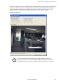
Using Your Appliance
i
Preface
VCCI
Cleaning
Use only a dry cloth to clean the appliance. To clean your appliance, gently wipe the surface of the
appliance with a dry cloth.
Misuse
Use your appliance ONLY in the manner specified. If the equipment is used in a manner not specified, the
protection provided by the equipment may be impaired. NetBotz is not responsible for misuse.
Improper Use of Audio/Video Recording Capabilities
Attention: THE EQUIPMENT CONTAINS, AND THE SOFTWARE
ENABLES, AUDIO/VISUAL AND RECORDING CAPABILITIES, THE
IMPROPER USE OF WHICH MAY SUBJECT YOU TO CIVIL AND
CRIMINAL PENALTIES. APPLICABLE LAWS REGARDING THE USE OF
SUCH CAPABILITIES VARY BETWEEN JURISDICTIONS AND MAY
REQUIRE AMONG OTHER THINGS EXPRESS WRITTEN CONSENT
FROM RECORDED SUBJECTS. YOU ARE SOLELY RESPONSIBLE FOR
INSURING STRICT COMPLIANCE WITH SUCH LAWS AND FOR STRICT
ADHERENCE TO ANY/ALL RIGHTS OF PRIVACY AND PERSONALTY.
USE OF THIS SOFTWARE FOR ILLEGAL SURVEILLANCE OR
MONITORING SHALL BE DEEMED UNAUTHORIZED USE IN
VIOLATION OF THE END USER SOFTWARE AGREEMENT AND RESULT
IN THE IMMEDIATE TERMINATION OF YOUR LICENSE RIGHTS
THEREUNDER.
Availability of Open Source Technologies
This product includes technologies that are governed by the GNU Public License. The GPL source code
contained in our products is available for free download from:
http://support.netbotz.com/gpl
ii
Using Your Appliance
Contents
Preface............................................................................... i
What’s New? .................................................................... 1
BotzWare Version 2.5 Features.................................................................................. 1
BotzWare Version 2.41 Features................................................................................ 1
BotzWare Version 2.4 Features.................................................................................. 1
BotzWare Version 2.3 Features.................................................................................. 2
BotzWare Version 2.2.2 Features............................................................................... 3
BotzWare Version 2.2 Features.................................................................................. 4
BotzWare Version 2.1.3 Features............................................................................... 4
BotzWare Version 2.1.2 Features............................................................................... 5
BotzWare Version 2.1.1 Features............................................................................... 5
BotzWare Version 2.1 Features.................................................................................. 5
About the Interfaces ........................................................ 7
The Basic View ........................................................................................................... 7
Basic View System Requirements......................................................................... 7
The Advanced View .................................................................................................... 7
Advanced View System Requirements ................................................................. 8
Appliance SSL Support............................................................................................... 8
About the Basic View .................................................... 11
Accessing the Basic View ......................................................................................... 11
Basic View Panes Accessible by Privilege Set.................................................... 12
Interface Navigation .................................................................................................. 12
Using the Basic View on Your PDA .......................................................................... 13
Using the Simplified Basic View .......................................................................... 14
Basic View: Monitoring Appliances ............................. 17
Viewing Sensor Readings ................................................................................... 17
Viewing Camera Images ..................................................................................... 18
Viewing Alerts...................................................................................................... 18
Viewing Maps ...................................................................................................... 19
Viewing Graphs ................................................................................................... 20
Triggering Relay Outputs..................................................................................... 21
Using Your Appliance
iii
Basic View: Configuring Appliances ........................... 23
Configuring the Appliance ................................................................................... 23
Configuring Camera Pod 120s and Integrated Cameras .................................... 23
Configuring CCTV Adapter Pod 120s.................................................................. 23
Configuring Sensor Pod 120s.............................................................................. 23
Configuring Integrated Sensor Pods (NetBotz 320/420 Only)............................. 24
Configuring 4-20mA Sensor Pods ....................................................................... 24
Configuring Output Relay Pod 120s .................................................................... 25
Configuring Power Control Pods ......................................................................... 25
Configuring Serial and RS232-Based Sensors ................................................... 27
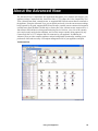
About the Advanced View............................................. 29
Adding Appliances .................................................................................................... 30
Accessing and Logging Into the Appliance Using the Advanced View ..................... 30
Advanced View Panes Accessible by Privilege Set ............................................ 31
Interface Navigation .................................................................................................. 31
The Navigation Pane ........................................................................................... 31
The Sensor Data Pane ........................................................................................ 32
The Action/Information Pane ............................................................................... 33
Advanced View Menus ............................................................................................. 34
Using NetBotz Central Post-Only Mode .............................................................. 34
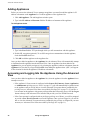
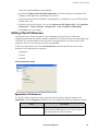
Editing Client Preferences ........................................................................................ 35
Appearance Preferences..................................................................................... 35
General Preferences ........................................................................................... 36
Network Preferences ........................................................................................... 37
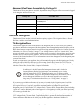
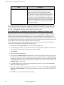
Performing Configuration Tasks ............................................................................... 37
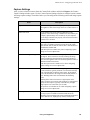
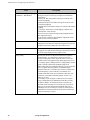
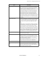
Pod and Alert Settings Tasks .............................................................................. 37
Appliance Settings Tasks .................................................................................... 40
Advanced View: Monitoring Appliances ..................... 43
Viewing Camera Images........................................................................................... 43
Image Zooming.................................................................................................... 45
Recording Camera Images.................................................................................. 45
Viewing Alerts ........................................................................................................... 47
Saving Picture Sequences to Your System......................................................... 49
Viewing Maps............................................................................................................ 50
Creating and Editing Maps .................................................................................. 51
Viewing Graphs......................................................................................................... 51
Advanced View: Configuring the Appliance ............... 55
Pod and Alert Settings Tasks .............................................................................. 55
Appliance Settings Tasks .................................................................................... 57
iv
Using Your Appliance
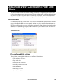
Advanced View: Configuring Pods and Alerts........... 59
Alert Actions ............................................................................................................. 59
Pre-configured Alert Actions ............................................................................... 59
Available Alert Notification Methods.................................................................... 60
Creating Alert Actions ......................................................................................... 61
Alert Profile ............................................................................................................... 62
The Default Alert Profile ...................................................................................... 63
Creating an Alert Profile ...................................................................................... 63
Creating an Alert Sequence ................................................................................ 64
Globally Disabling Alert Notifications .................................................................. 65
Camera Pods........................................................................................................... 66
Settings ............................................................................................................... 67
Capture Settings ................................................................................................. 69
Masking Settings................................................................................................. 72
Visual Mode Settings .......................................................................................... 75
Sensor Settings................................................................................................... 76
Device Crawlers ....................................................................................................... 77
About Advanced Device Crawlers....................................................................... 78
Adding, Editing, and Removing SNMP Targets .................................................. 79
Specifying Global SNMP Settings....................................................................... 80
Sensor Settings................................................................................................... 81
IPMI Devices ............................................................................................................ 82
Adding, Editing, and Removing IPMI Devices..................................................... 83
Sensor Settings................................................................................................... 84
Output Control .......................................................................................................... 86
Output Control Label Settings ............................................................................. 87
Output Control External Port Settings ................................................................. 87
Output Control Sensor Settings .......................................................................... 90
Periodic Reports ....................................................................................................... 92
Configuring Periodic E-mail Reports ................................................................... 92
Configuring Periodic FTP Reports ...................................................................... 94
Configuring Periodic HTTP Reports.................................................................... 95
Sensor Pods ............................................................................................................. 97
Settings ............................................................................................................... 97
Sensors ............................................................................................................... 98
External Ports...................................................................................................... 99
Wireless Sensor Discovery..................................................................................... 104
Advanced View: Configuring Appliances ................. 105
Backup.................................................................................................................... 105
Clock....................................................................................................................... 106
Custom Audio Clips ................................................................................................ 107
Adding Custom Audio Clips .............................................................................. 107
Deleting Custom Audio Clips ............................................................................ 107
DNS ........................................................................................................................ 107
Using Your Appliance
v
Configuring DNS Settings.................................................................................. 107
Configuring Dynamic DNS Settings................................................................... 108
E-mail Server .......................................................................................................... 108
External Storage ..................................................................................................... 110
Configuring Your Appliance to Use External Storage........................................ 110
Using an Extended Storage System.................................................................. 111
Using a Windows Share .................................................................................... 111
Using an NFS Mount ......................................................................................... 112
Removing External Storage............................................................................... 113
IP Filter.................................................................................................................... 113
License Keys........................................................................................................... 114
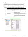
Location .................................................................................................................. 115
Log .......................................................................................................................... 116
Network Interfaces .................................................................................................. 118
Ethernet Network Interface................................................................................ 118
Wireless Network Interface................................................................................ 120
PPP/Modem............................................................................................................ 122
Managing your Appliance Using a Dial-In PPP Connection .............................. 125
PPP Performance Considerations..................................................................... 125
Using SIM Security ............................................................................................ 127
Upgrading Over PPP ......................................................................................... 127
Proxy....................................................................................................................... 128
Region..................................................................................................................... 129
Pod Sharing ............................................................................................................ 130
Restore ................................................................................................................... 132
Serial Devices ......................................................................................................... 133
Removing Serial Ports....................................................................................... 133
SMS ........................................................................................................................ 133
SNMP...................................................................................................................... 135
SSL ......................................................................................................................... 136
Upgrade .................................................................................................................. 137
Users....................................................................................................................... 137
Web Server ............................................................................................................. 140
Advanced View: Defining Thresholds ....................... 141
Analog Sensor Thresholds...................................................................................... 141
State Sensor Thresholds ........................................................................................ 141
Defining Analog Thresholds.................................................................................... 141
Maximum Value Threshold................................................................................ 142
Minimum Value Threshold................................................................................. 143
Range Threshold ............................................................................................... 145
Above Value for Time Threshold ....................................................................... 147
Below Value for Time Threshold ....................................................................... 148
Rate of Decrease Threshold.............................................................................. 150
Rate of Increase Threshold ............................................................................... 152
Defining State Thresholds...................................................................................... 154
vi
Using Your Appliance
Alert State Threshold ........................................................................................ 154
Alert State for Time Threshold .......................................................................... 155
State Mismatch Threshold ................................................................................ 157
State Mismatch For Time Threshold ................................................................. 159
Advanced View: Creating Alert Actions.................... 161
Creating an Activate Button Output Alert Action..................................................... 161
Creating a Call Web Services Alert Receiver Alert Action...................................... 162
Creating a Play Audio Alert Action ......................................................................... 162
Creating a Play Custom Audio Alert Action ............................................................ 163
Creating a Send Custom HTTP Get Alert Action.................................................... 164
Example Target URLs....................................................................................... 165
Creating a Send Custom Text File to FTP Server Alert Action............................... 165
Creating a Send Data to FTP Server Alert Action .................................................. 166
Creating a Send E-mail Alert Action ....................................................................... 168
Creating a Send HTTP Post Alert Action................................................................ 170
Creating a Send Short Message E-mail Alert Action.............................................. 171
Creating a Send SNMP v1 Trap Alert Action.......................................................... 172
Creating a Send Wireless SMS Message Alert Action ........................................... 173
Creating a Set Switch Output State Alert Action .................................................... 174
Add-Ons: Advanced Device Crawlers....................... 177
OID-Specific Monitoring.......................................................................................... 177
Enhanced Environmental Monitoring ................................................................ 177
Enhanced Alert Notification............................................................................... 177
Enabling Advanced Device Crawlers ..................................................................... 177
Using Advanced Device Crawlers .......................................................................... 178
The Device Definition Files View....................................................................... 178
The Advanced Data Sensor Set........................................................................ 179
The Supplemental OIDs View ........................................................................... 179
Add-Ons: RAE Systems Sensors Option.................. 181
Additional Features................................................................................................. 181
Remote RAE Clients and Servers .......................................................................... 181
Enabling RAE Systems Sensors Option................................................................. 181
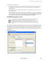
New Pod/Sensor Settings Task: RAE Systems Sensors ....................................... 182
New Appliance Settings Task: RAE Systems......................................................... 182
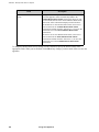
The RAE Systems Devices Tab........................................................................ 183
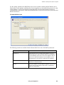
The Remote RAE Server Tab ........................................................................... 184
Using Your Appliance
vii
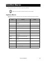
BotzWare Macros......................................................... 187
Appliance Macros ................................................................................................... 187
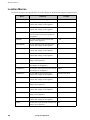
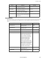
Location Macros...................................................................................................... 188
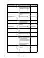
Alert Macros............................................................................................................ 189
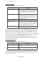
Overloaded Appliances: Symptoms & Solutions ..... 193
Overloaded Appliances: Symptoms........................................................................ 193
Overloaded Appliances: Solutions .......................................................................... 193
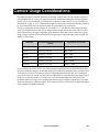
Camera Usage Considerations................................... 197
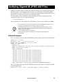
Verifying Signed M-JPEG AVI Files ........................... 199
Output Examples .................................................................................................... 199
viii
Using Your Appliance
What’s New?
Users who are familiar with the core features delivered in BotzWare version 2.0 can use this version
history to quickly identify new or improved features, as well as information about features that were
introduced in previous BotzWare releases.
BotzWare Version 2.5 Features
In addition to additional hardware support and performance improvements, BotzWare 2.5 introduced
the following new features and enhancements:
• New Play Custom Audio Alert Action: Used in conjunction with the Custom Audio Alerts
task, this new alert action enables your NetBotz appliance to play customized, user-specified
audio alerts. For more information on the Play Custom Audio alert action see “Creating a Play
Custom Audio Alert Action” on page 163.
• New Custom Audio Clips Configuration Task: Use this new task to upload custom audio
clips to your NetBotz appliance, or to delete previously uploaded clips from the NetBotz
appliance. Once uploaded, audio clips can be used with the new Play Custom Audio alert
action. For more information on the Custom Audio Clips task see “Custom Audio Clips” on
page 107.
BotzWare Version 2.41 Features
In addition to additional hardware support and performance improvements, BotzWare 2.41
introduced the following new features and enhancements:
• Enhanced SeaLink PIO-48 Support: NetBotz 500 appliances now support connection of up
to 4 SeaLink PIO-48 dry contact hub devices (increased from 2).
• New CCTV Pod Configuration Options: CCTV Pod configuration settings now include
settings specifically designed for use with black and white CCTV cameras.
• MTU Settings Support: Added support for specifying MTU settings on Ethernet and 802.11
network interfaces.
BotzWare Version 2.4 Features
In addition to additional hardware support and performance improvements, BotzWare 2.4 introduced
the following new features and enhancements:
• New Map View: Appliances that have the BotzWare Premium Software Module 2.4 installed
can now Display maps that have been configured for use with the appliance. The alert state of
all devices shown on the Map View are indicated with simple color coding (red indicates that an
alert state currently exists, while green indicates that no alert state is currently being reported by
the sensor or device).
• New IPMI Devices Task: Appliances that have the BotzWare Premium Software Module 2.4
installed can use the IPMI Devices task to add network-attached, Intelligent Platform
Management Interface-enabled devices to the list of devices that are monitored by your NetBotz
appliance.
• New Pod Sharing Capabilities: NetBotz 500 appliances that have the BotzWare Premium
Software Module 2.4 installed can now connect with and receive data directly from devices
Using Your Appliance
1
What’s New?
integrated with or connected to NetBotz 320, 420 or 500s in your network. Once a pod has been
shared with the NetBotz 500, it functions as though it were connected directly to the appliance.
• NAS Support Added to External Storage Task: NetBotz 500 appliances that have the BotzWare
Premium Software Module 2.4 installed can now use a network attached storage device (a Windows
share or an NFS mount) for External Storage functionality.
• Enhanced, Component-Level Logging: Appliance logging capabilities are now broken out into
specific components and/or functions. By default, all components log at the level specified by the
Global Level setting. However, you can also specify a unique login level setting for each
component.
• Include Maps and Graphs in Periodic Reports: Maps and Graphs can now be included in
periodic e-mail and FTP reports generated by your appliance.
BotzWare Version 2.3 Features
In addition to additional hardware support and performance improvements, BotzWare 2.3 introduced the
following new features and enhancements:
• New Configuration Wizard: This configuration wizard, which runs automatically when the
Advanced View is used to access the appliance after installation, guides the user through all the
steps necessary to get their new appliance up and running.
• Camera Settings Enhancement — Interactive Mode Limit: Specifies the maximum image
resolution that will be made available to users that are using the appliance interactively (such as
viewing images from the Cameras View in the Advanced View). This can be used to limit the
performance impact that can be caused by multiple clients with high image resolution settings
accessing your appliances interactively. For more information see “Settings” on page 67.
• Advanced Device Crawlers Enhancement — Delete SNMP Sensors if Not Found: Allows the
user to automatically remove previously defined SNMP-based sensors on a target when, after a
successful scan, the sensors are found to no longer be present (no longer defined, unavailable, and
so forth). If the sensors are not deleted, they will be displayed with sensor reading values of “N/A”
or “null.” For more information see “Device Crawlers” on page 77.
• New Picture Export Formats feature for Send E-Mail and Send Data to FTP Server Alert
Actions: Appliances that have the BotzWare Premium Software Module 2.3 installed can now send
images captured by the appliance cameras as JPEGs, M-JPEG AVI Files, or Signed M-JPEG AVI
files. M-JPEG AVI files are motion picture files that can be played using standard media player
software (such as Windows Media Player). Signed files provide proof that the generated images
have not been tampered with or altered in any way, and are therefore more likely to be admissible as
evidence in legal proceedings. For more information see “Creating a Send Data to FTP Server Alert
Action” on page 166 and “Creating a Send E-mail Alert Action” on page 168.
• Block Out Masking Functionality: Appliances that have the BotzWare Premium Software Module
2.3 installed can now configure cameras so that specified areas of the image cannot be seen. For
example, an administrator could place a Block Out Mask over the area of the image that shows a
monitor image, thereby preventing users from seeing the information that is shown on the monitor.
For more information see “Masking Settings” on page 72.
2
Using Your Appliance
What’s New?
BotzWare Version 2.2.2 Features
In addition to additional hardware support and performance improvements, BotzWare 2.2.2 introduced
the following new features and enhancements:
• 4-20mA Sensor Pod Support: Support for the 4-20mA Sensor Pod, which enables you to connect
up to four 4-20mA sensors to your NetBotz 420 or NetBotz 500 appliance. For more information
see “Configuring 4-20mA Sensor Pods” on page 24 and “Sensor Pods” on page 97.
• BotzWare now supports the use of 0-5V sensors, which can be connected to any external sensor
port using a NetBotz 0-5V Sensor Cable. 4 external sensor ports are integrated with NetBotz 320 or
420 appliances, and are included on each Sensor Pod 120 as well.
• Added BotzWare Web Services Interfaces: The NetBotz BotzWare Web Services interfaces are
intended to provide a set of common, programmer-friendly APIs to 3rd party product and solution
developers, as well as end customers. For more information, see the BotzWare V2.x Web Services
Specification PDF, included on your BotzWare CD and available from the NetBotz support web
site.
• Call Web Services Alert Receiver (New Alert Action): A new alert action that is designed for use
with the BotzWare Web Services Interface (see above).
• Added support for the SeaLINK PIO-48. When you connect a SeaLINK PIO-48 (available from
Sealevel Systems) to a USB port on your NetBotz 500 or NetBotz 420 appliance, it provides 48
digital connections. This enables you to connect and monitor up to 48 dry contact sensors from a
single appliance without requiring you to purchase and deploy a large number of Sensor Pod 120s.
• Added support for RAEWatch (new sensor type).
• New Simplified Basic View for Use with Supported PDAs: NetBotz appliances now support a
simplified version of the Basic View that can be viewed using supported Personal Digital Assistants
(PDAs). Supported PDAs include Palm Tungsten handhelds running Palm OS 5.2.1, HP iPAQ
handhelds running Windows Mobile Pocket PC 2003 or Windows Mobile Pocket PC 2003, and
Blackberry 6xxx & 7xxx Series Devices running 3.7 OS. For more information see “Using the
Simplified Basic View” on page 14.
• Send Custom Text File to FTP Server (New Alert Action): Sends a customized text file with
user-specified content to an FTP server. This alert action type enables you to use macros supported
by BotzWare (including Appliance, Location, and Alert macros) to define the name of the directory
on the server in which custom text files will be stored and the base filename that will be used for the
text files.
• Advanced Device Crawlers has been enhanced to enable it to monitor NetBotz appliances
running BotzWare 2.x.
• Additional Network Interface Settings: When configuring a network interface, you can now
specify both the network speed and the duplex mode for the interface.
• Added Include XML-encoded Alert Parameter (xmlalert), a check box for the Custom HTTP
Get action that appends the parameter xmlalert=<xml alert encoding> to the provided URL for the
action. The encoded XML is the same as is generated by the HTTP POST code, but is URL-
Using Your Appliance
3
What’s New?
encoded to enable those that can't easily handle “multi-part/form-data” encoded POSTS to get the
XML for the alert.
• BotzWare OIDs Have Been Enhanced: A 1000x and a 1000000x column have been added a to the
OtherNumericSensor table, enabling customers to more easily gather RTT Ping data from devices
that have a RTT Ping time of less than 1 second.
• Enhanced Logging for E-mail Operation Failures: Added protocol debug logging for all SMTP
protocol messages to all e-mail operations (alert, periodic reports, and test e-mail). Logging info
appears at the INFO level.
• SMS Alert Action macros now show Return To Normal information.
BotzWare Version 2.2 Features
In addition to additional hardware support and performance improvements, BotzWare 2.2 (released
August 18, 2004) introduced the following new features and enhancements:
• Support for Navigation Pane Folders: Folders enable you to create virtual groups of pods and
devices that can be used to simplify organization of your various pods and devices for management
purposes. For more information see “Using Folders” on page 32.
• Expanded Support for RAE Systems Devices: RAE Systems Sensors Option is a license keyenabled BotzWare enhancement that enables you to use a variety of RAE Systems toxic vapor and
gas sensors with your appliances. BotzWare 2.2 support the use of MultiRAE Plus, ppbRAE,
miniRAE, AreaRAE, and RAELink devices with your appliance. For more information see “AddOns: RAE Systems Sensors Option” on page 181
• Support for Remote RAE Client/Server Communications: This functionality enables you to
aggregate the data reported by all of your appliance-connected RAE Systems devices into a single
interface, and to set thresholds, monitor alerts, and graph data reported by the RAE Systems devices
on Remote RAE Clients just like any other sensor connected to and supported by your appliance.
For more information see “Remote RAE Clients and Servers” on page 181.
• “Alerting Sensors” Added to Navigation Pane: Alerting Sensors is a new “virtual device” that
appears in the Navigation Pane and that presents a dynamic overview of all currently alerting
sensors as reported by the appliance as well as pods and other devices connected to the appliance.
For more information see “The Navigation Pane” on page 31.
• Ability to Lock Selection in the Navigation Pane: This new functionality enables you to lock the
Navigation Pane so that only a specific device is selected.Once the Navigation pane is locked, you
will not be able to select any other devices from the Navigation pane until you unlock the pane, and
the Advanced View will automatically start with the pane in the locked state.
• Network Interface Sensors Added: New sensors that specify the link status of each network
interface installed in your appliance are now available when the appliance is selected from the
Navigation Pane.
BotzWare Version 2.1.3 Features
BotzWare 2.1.3 (released April 30, 2004) introduced the following new features and enhancements:
• Wireless Receiver 120 and THS-100 Wireless Temperature/Humidity Sensor Support: Support
for Wireless Receiver 120s and THS-100 Wireless Temperature/Humidity Sensors. For more
information see “Sensor Pods” on page 97, and “Wireless Sensor Discovery” on page 104.
• Support for RAE Systems MultiRAE Plus: Enables the addition of a license key-enabled
enhancement that permits use of RAE Systems MultiRAE Plus toxic vapor and gas sensors with
4
Using Your Appliance
What’s New?
supported appliances. Designed as a “building block” system, the MultiRAE can be configured
from a simple, inexpensive Oxygen/LEL monitor all the way to an affordable five gas monitor for
total protection in toxic environments.
• Send Custom HTTP GET Alert Action: New alert action that enables you deliver alert
notifications as custom HTTP GET commands. The URL generated as a result of the alert action is
completely user definable, and can include BotzWare macro values. For more information see
“Creating a Send Custom HTTP Get Alert Action” on page 164
• Support for Additional Wireless Network Adapters: In addition to previously supported
adapters, BotzWare 2.1.3 includes support for the following:
– D-Link Air Xpert DWL-AG650 Tri-Mode Dualband Wireless CardBus Adapter
– Netgear WAG511 Dual Band Wireless PC Card (32-bit CardBus)
– Cisco Aironet 802.11a/b/g Wireless CardBus Adapter
BotzWare Version 2.1.2 Features
BotzWare 2.1.2 (released February 20, 2004) introduced the following new features and enhancements:
• Output Control: New functionality that provides user interface and alert notification support for
use with supported digital output devices such as the Output Relay Pod 120 and Power Control
Pods. For more information see “Associating Relays or Switches with Integrated Cameras and
Camera Pods” on page 68, “Output Control” on page 86, “Creating an Activate Button Output Alert
Action” on page 161, and “Creating a Set Switch Output State Alert Action” on page 174.
• Multiple Alert Profiles: Enhanced Alert Profile functionality now enables the creation of multiple
unique Alert Profiles. This enables you to define distinctive notification or action responses for
sensor thresholds. For more information see “Alert Profile” on page 62.
BotzWare Version 2.1.1 Features
BotzWare 2.1.1 (released December 5, 2003) introduced the following new features and enhancements:
• Device Crawlers: New functionality that enables you to monitor the critical status information of
up to 48 remote SNMP targets (such as servers, routers, and switches). If any operational difficulties
are noted on a monitored target your appliance can generate an alert notification, enabling you to
quickly address the problem. For more information see “Device Crawlers” on page 77.
• Support for Advanced Device Crawlers: Enables the addition of a license key-enabled
enhancement to Device Crawlers that greatly extends your ability to monitor the operational status
of your SNMP targets. Advanced Device Crawlers extends the capabilities of Basic Device
Crawlers to provide far more detailed device-specific information and to enable OID-specific
monitoring and alerting. For more information see “Add-Ons: Advanced Device Crawlers” on
page 177.
BotzWare Version 2.1 Features
BotzWare 2.1 (released October 23, 2003) introduced the following new features and enhancements:
• Serial Device Support: Provides an extensible framework for the management of serial devices.
With this functionality, appliances can detect and manage multiple serial-class devices (including
supported modems, GPS devices, and various RS-232 and RS-485 attached devices). Supported
serial devices can be connected using an appliance expansion slot (expansion slots are not available
Using Your Appliance
5
What’s New?
on all appliances), directly to a USB port, or through a number of supported USB-to-Serial adapter
cables. For more information see “Serial Devices” on page 133.
• PPP Support: Provides support for point-to-point protocol network connectivity using supported
wired or GSM/GPRS modems. For more information see “PPP/Modem” on page 122.
• SMS Messaging Support: When used in conjunction with a supported GSM/GPRS modem, an
additional alert action is enabled that permits delivery of alert notifications as SMS messages. For
more information see “SMS” on page 133 and “Creating a Send Wireless SMS Message Alert
Action” on page 173.
• Support for CCTV Adapter Pods: Designed for use with your appliance and a single closed
circuit television (CCTV) or other video source, the CCTV Adapter Pod accepts multi format SVideo and Composite Video and features DIN, BNC and RCA input jacks. This pod also features a
USB port that enables the pod to be tethered to the appliance using a standard USB cable. Using the
CCTV Adapter Pod, your analog video source is digitally converted and integrated with your
physical security solution. Streaming audio (using the pod’s integrated microphone or an external
microphone connected to the pod) is also available.
• Support for PS100 Particle Sensor: The PS100 Particle Sensor enables your appliance to monitor
a location for the presence or dust and other particulates larger than 1 micro meter.
• Support for Supported NMEA-Compliant GPS Receivers: Enables your NetBotz 500 to report
status and readings from supported GPS receivers. GPS receivers associate location information
(such as latitude, longitude, altitude, and so forth) with alert data, which can be useful for mobile
applications.
• IP Filtering: Provides full support for IP-address based packet filtering, allowing for an additional
level of protection against illegal access or denial-of-service attacks. For more information see “IP
Filter” on page 113.
• Improved SSL Security: The SSL implementation used by BotzWare has been upgraded to
OpenSSL 0.9.7c, providing support for 256-bit AES with RSA and SHA1 and 128-bit AES with RSA
and SHA1.
• HTTP Compression: The Basic View and Advanced View interfaces now support HTTP
compression, significantly reducing non-picture related traffic and improving interface performance
when used over slower network interfaces (such as PPP or ISDN).
6
Using Your Appliance
About the Interfaces
NetBotz appliances support two interfaces for the purposes of monitoring sensor data, viewing
camera images, triggering relay outputs, and appliance configuration: The Basic View and the
Advanced View. Brief descriptions of each of these interfaces follow.
The Basic View
The Basic View enables authorized users to use a supported web browser to view the current sensor
data, image capture, and other appliance data in a simple HTML-based interface. In addition, some
basic appliance configuration can be performed, and relay output actions triggered, using the Basic
View. However, the configuration tasks that are available from the Basic View are highly limited and
are included primarily to assist in initial appliance installation and setup. This view is provided
primarily for user’s who wish to use a web browser to view appliance status and who are either
unwilling or unable to install the software required to use the Advanced View.
Basic View System Requirements
To use the Basic View to monitor or configure an appliance, your system must be running one of the
following supported web browsers:
• Netscape Navigator 4.79, 6.0 or later
• Internet Explorer 5.5 or later
• Mozilla 1.3 or later
NetBotz appliances running BotzWare version 2.2.2 or later also support a simplified version of the
Basic View that can be viewed using the following Personal Digital Assistants (PDAs):
• Palm Tungsten handhelds running Palm OS 5.2.1, with Palm OS 5 Web Browser
• HP iPAQ handhelds running Windows Mobile Pocket PC 2003 or Windows Mobile Pocket PC
2003, with Pocket Internet Explorer
• Blackberry 6xxx & 7xxx Series Devices running 3.7 OS with WebViewer 3.5 from ReqWireless
For more information, see “Using the Basic View on Your PDA” on page 13.
The Advanced View
The Advanced View is the primary user interface for appliance monitoring and management. This
interface enables authorized users to view current sensor data, camera images, and other appliance
data in a custom Java application. The Advanced View also enables authorized users to trigger relay
output actions and configure all appliance features. Unlike the Basic View (which uses a web browser
to display the appliance data), the Advanced View is a stand-alone application that must be installed
on a supported network-attached system.
Using Your Appliance
7
About the Interfaces
Advanced View System Requirements
To run the Advanced View application, your system must meet these system requirements:
• Minimum Configuration:
– Either a PC with an IntelTM PentiumTM II 450 processor (or equivalent) running Microsoft
Windows (2000 or XP SP1), Red Hat EL 3, Fedora Core 3, or Debian GNU 3 or a Sparc
workstation running Solaris 9 with all patch bundles recommended by Sun installed
– 128MB RAM
– Sun’s Java Runtime Environment v 1.4.1_03 (if not present, the JRE will be installed
automatically during Advanced View installation)
• Recommended Configuration:
– IntelTM PentiumTM III 600 processor (or equivalent)
– 256MB RAM
For instructions on installing the Advanced View, see the About Your Appliance booklet that was included
with your appliance.
Appliance SSL Support
By default, SSL is enabled on your appliance and all browser/appliance interaction can be carried out
using SSL by connecting to the appliance using a URL formatted beginning with “https” (for example,
https://IP_address). Your appliance can also use SSL when posting alert notification and sensor data to
web servers, and the Advanced View can be configured to use SSL when communicating with your
appliance.
8
Using Your Appliance
About the Interfaces
The SSL certificate that is needed for SSL communications is self-generated by the appliance (“selfsigned”) at first power-up and requires no user-interaction. If the hostname or domain of the appliance is
changed the certificate is automatically regenerated, as the certificate includes the fully-qualified DNS
name of the appliance. Alternately, you can request and install a signed SSL certificate from a
certification authority if desired. For information on how to install a signed SSL certificate, see “SSL” on
page 136.
• Your browser will generate a warning the first time you attempt to
communicate with the appliance using SSL after a new self-generated SSL
certificate has been created. This is normal behavior and you can accept the
certificate without concern.
• To use SSL when communicating with the appliance using the Basic View,
use https:// at the beginning of the web address of the appliance. For more
information about the Basic View see “About the Basic View” on page 11.
• To use SSL when posting alert notifications and sensor data to a web server,
use https:// at the beginning of the web address of the web server when
configuring the Send Using HTTP Post Alert Action. For information on
configuring Send Using HTTP Post Alert Actions see “Creating Alert
Actions” on page 61 and “Creating a Send HTTP Post Alert Action” on
page 170.
Note
• To use SSL when monitoring or managing your appliance using the Advanced
View, check the Use SSL check box in the Advanced View interface. For
more information about the Advanced View see “The Advanced View is a
stand-alone Java application that enables you to monitor and configure your
appliance and any Camera Pod 120s, Sensor Pod 120s, CCTV Adapter Pod
120s, Output Relay Pod 120s, 4-20mA Sensor Pods, external sensors, or
supported RS232-based sensors that are connected to the appliance. Using the
Advanced View, you can quickly and easily view the current sensor readings
being reported by any pods, supported RS232-based sensors, external sensors
connected to integrated external sensor ports (NetBotz 320/420 only) or
Sensor Pod 120s, 4-20mA sensors connected to a 4-20mA Sensor Pod, and
devices being monitored using Device Crawlers, view a list of all currently
active and recently resolved alert conditions, and view the images currently
being captured by any Camera Pod 120s or CCTV Adapter Pod 120s
connected to your appliance. In addition, the Advanced View provides
complete appliance and pod configuration functionality, enabling you to
perform all of the tasks necessary for complete management of all of your
appliances and pods.” on page 29.
Using Your Appliance
9
About the Interfaces
10
Using Your Appliance
About the Basic View
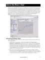
The Basic View is an HTML-based interface that enables you to view data about all objects that are
currently being monitored by your appliance. Using a supported web browser, you can quickly and
easily view the current sensor readings being reported by any Camera Pod 120s, Sensor Pod 120s,
external sensors connected to Sensor Pod 120s, and devices being monitored using Device Crawlers,
view a list of all currently active and recently resolved alert conditions, and view the images currently
being captured by any Camera Pod 120s connected to your appliance. In addition, the Basic View
enables you to trigger relay output actions and provides some simple sensor configuration
capabilities to assist you during the initial appliance installation process.
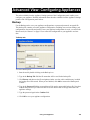
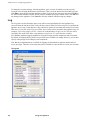
Accessing the Basic View
To access an appliance using the Basic View, point a supported web browser at the hostname or IP
address of the appliance.
• If the appliance’s Guest account is configured with a Sensor (No Camera), Sensor,
Application, or Administrator privilege set (see “Users” on page 137) you will automatically
be granted access to the appliance and you will be able to view the Basic View panes that are
permitted by the privilege set (see “Basic View Panes Accessible by Privilege Set” on page 12).
If you have a user account on the appliance with greater privileges than those allowed to guests,
click the Logon link in the lower left-hand corner of the Basic View (beside the company logo)
and provide your User ID and Password.
• If the Guest account is configured with no privileges (privilege set of None), you will be
prompted to provide a User ID and Password to access the appliance. Once you have logged
in, you will be able to view the Basic View panes that are permitted by the privilege set assigned
to your user account (see “Basic View Panes Accessible by Privilege Set” on page 12).
Using Your Appliance
11
About the Basic View
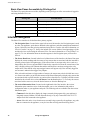
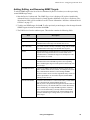
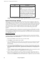
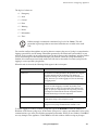
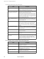
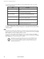
Basic View Panes Accessible by Privilege Set
The Basic View panes that are accessible, depending on the privilege set of the account that is logged in
and using the Basic View, are:
Privilege Set
Accessible Panes
Administrator
Cameras, Graphs, Alerts, Setup, and About panes.
Application
Cameras, Graphs, Alerts, and About panes.
Sensor
Cameras, Graphs, and About panes.
Sensor (No Camera)
Graphs and About panes.
None
Does not permit access to any appliance features.
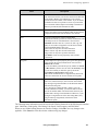
Interface Navigation
The Basic View interface is divided into three primary regions:
• The Navigation Pane: Located in the upper-left corner of the interface, the Navigation pane is used
to select your appliance, pods that are attached to the appliance, and other managed and monitored
objects, such as devices that are being monitored using Device Crawlers (for more information, see
“Device Crawlers” on page 77). It may also include one or more folders (virtual groupings of pods
and other devices created using the Advanced View. For more information see “Using Folders” on
page 32). To view information about an item that appears in the Navigation pane you must first
select it.
• The Sensor Data Pane: Located in the lower-left hand corner of the interface, the Sensor Data pane
displays the current readings and alert status of any sensors that are associated with the item that is
currently selected in the Navigation pane. If the selected item is an output relay device (such as a
Output Relay Pod 120 or a supported RS232-based relay output device) then the current state of the
relay is displayed along with a button that enables authorized user accounts to trigger the relay
output action. Note that the relay output trigger buttons will appear only if the currently logged-in
user account is authorized to trigger relay outputs.
If the selected item features a large number of sensors, the sensors may also be divided into sensor
sets. Sensor sets enable you to filter the contents of the Sensor Data pane to display only sensors that
are associated with a specific interface or portion of the selected device. To display all of the sensors
included in the selected device select All Sensors from the Set drop-box. To view only the sensors
associated with a sensor set, select the desired sensor set from the Set drop-box.
• The Action/Information Pane: Located on the right-hand side of the interface, the Action/
Information pane contains a series of tabs that enable you to view information and perform
configuration tasks on your appliance and pods. The following tabs are available from the Action/
Information pane:
– Cameras: Select this tab to display the images currently being captured by your appliance’s
integrated camera (NetBotz 320 and 420 models only) or by any Camera Pod 120s or CCTV
Adapter Pod 120s connected to the appliance.
– Alerts: Select this tab to view alerts that are currently being reported by the appliance, any pods
that are connected to the appliance, or any devices that are being monitored using Device
12
Using Your Appliance
About the Basic View
Crawlers. Alerts that have occurred in the past 24 hours, but which have been resolved, can be
shown as well.
– Maps: Select this tab to view any Advanced View maps that have been configured for use with
this appliance. The Map View, available for use only on appliances for which the BotzWare
Premium Software Module 2.4 has been purchased, enables you to view user-created maps that
show the location of your NetBotz appliances, pods, and sensors. The alert state of all devices
shown on the Map View are indicated with simple color coding (red indicates that an alert state
currently exists, while green indicates that no alert state is currently being reported by the sensor
or device). The BotzWare Premium Software Module is available as part of NetBotz Extended
Warranty Coverage. For more information, contact your NetBotz authorized reseller or the
NetBotz support team).
– Graphs: Select this tab to display graphs of up to 24 hours of environmental data that has been
collected from any sensor that is connected to the appliance (including sensors that are built into
pods, external sensors connected to Sensor Pod 120s, devices that are being monitored using
Device Crawlers, and RS232-based sensors that are connected to your appliance using a USB-toserial-port adapter).
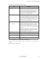
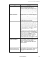
– Setup: Select this tab to specify a label that can used to uniquely identify the appliance and any
pods that are connected to the appliance. If you have output control devices connected to your
appliance, you can use this tab to specify output types and labels for each relay. This tab also
enables you to configure and uniquely label any external sensors that may be connected to the
external sensor ports on a NetBotz 320 or 420 appliance, Sensor Pod 120, or 4-20mA Sensor
Pod, as well as any devices that are being monitored using Device Crawlers.
– About: Select this tab to display information about your appliance and all connected pods.
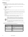
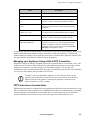
Using the Basic View on Your PDA
NetBotz appliances running BotzWare version 2.2.2 or later also support a simplified version of the Basic
View that can be viewed using the following Personal Digital Assistants (PDAs):
• Palm Tungsten handhelds running Palm OS 5.2.1, with Palm OS 5 Web Browser
• Palm handheld devices, such as the Treo PDA/Phone, running the Blazer web browser
• HP iPAQ handhelds running Windows Mobile Pocket PC 2003 or Windows Mobile Pocket PC
2003, with Pocket Internet Explorer
• Blackberry 6xxx & 7xxx Series Devices running 3.7 OS with WebViewer 3.5 from ReqWireless
To use the simplified Basic View, simply point your supported PDA’s web browser at the hostname or IP
address of the appliance.
• If the appliance’s Guest account is configured with a Sensor (No Camera), Sensor, Application,
or Administrator privilege set (see “Users” on page 137) you will automatically be granted access
to the appliance
• If the Guest account is configured with no privileges (privilege set of None), you will be prompted
to provide a User ID and Password to access the appliance. Log in to continue.
Using Your Appliance
13
About the Basic View
Using the Simplified Basic View
Due to the limited screen space and resolution available on PDAs, you will note a number of significant
differences in the Basic View with accessed with your PDA. The most significant difference is that unlike
the standard Basic View, which shows the Navigation, Sensor Data, and Action/Information panes
simultaneously, the simplified Basic View shows only a single region of the Basic View interface at any
time.
When you initially log in, you will see only the contents of the Navigation pane. From this pane, you can
“drill down” to the appliance and sensor data that you require. Using the PDA’s pen, select About to
display information about your appliance and all connected pods, or select the appliance or other
component (such as a pod or the Alerting Sensors group) to switch to the Sensor Data view for the
selected item. From the Sensor Data view, you can access graphs, alert reports, and camera images.
Select Back to return to the Navigation pane from the Sensor Data pane.
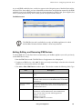
Viewing Graphs
To display a graph of environmental data that has been collected from a sensor, simply select from the
Reading column the current sensor reading beside the sensor that you want to graph. By default a graph
displaying data collected over the past 60 minutes is shown. Use the Time drop box to change the amount
of data to be graphed. Select Refresh to refresh the contents of the graph. Select Back to return to the
Sensor Data view from the Graph view.
Viewing Alerts
To display a list alerts associated with the selected component, simply select any current Alert reading
from the Status column to switch to the Alerts View. A list of alerts that are currently being reported by
the component you selected from the Navigation View is displayed. To include alerts that have occurred
in the past 24 hours but that have been resolved, check the Include Returned to Normal Alerts check box
in the Alerts View. Select Back to return to the Sensor Data view from the Alerts view.
For additional Alert Details, select any of the alerts that are listed in the Alerts View. Select Back to
return to the Alerts view from the Alert Details view.
Viewing Camera Images
To display the images currently being captured by a camera that is integrated with or connected to your
appliance, select the camera pod or the appliance from the Navigation pane, and then select the camera
link from the Sensor Data view. A camera image (in 160x120 mode, by default) is displayed. To change
the display mode, select a new setting from the Mode drop box. To change the rate at which the image is
updated, select a new setting from the Rate drop box. Select Back to return to the Sensor Data view from
the camera view.
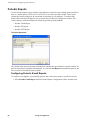
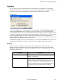
Configuring Your Appliance
Just like the standard Basic View, the simplified Basic View provides some simple sensor configuration
capabilities to assist you during the initial appliance installation process. Select from the Navigation pane
the appliance, pod, or other device you want to configure. Then, in the Sensor Data pane for that device,
select Setup. The settings available for configuration will be displayed in the resulting Configuration
pane.For example, you can:
• Configure and uniquely label any external sensors that may be connected to external sensor ports on
a NetBotz 320 or 420 appliance, Sensor Pod 120, or 4-20mA Sensor Pod
• Configure and uniquely label any devices that are being monitored using Device Crawlers.
• Specify output types and labels for each relay on output control devices connected to your
appliance.
14
Using Your Appliance
About the Basic View
Select Back to return to the Sensor Data view from the Setup view.
Using Your Appliance
15
About the Basic View
16
Using Your Appliance
Basic View: Monitoring Appliances
The Basic View is primarily designed to provide you with a simple-to-use appliance monitoring
interface that does not requiring the presence of the Advanced View application and Java Runtime
Environment. The monitoring tasks that are available when using the Basic View are viewing sensor
readings, viewing camera images, graphing collected sensor data, and viewing currently active and
resolved alert conditions.
Viewing Sensor Readings
You can use the Basic View to view the monitored value and alert status of any sensor that is
currently connected to the appliance. Sensors are included in the Camera Pod 120 (camera motion,
door switch, microphone plug, speaker plug) and Sensor Pod 120 (air flow, temperature, humidity,
dew point, audio, as well as up to 4 external sensors). NetBotz 320 and 420 models camera feature an
integrated camera and sensor pod and include camera motion, door switch, air flow, temperature,
humidity, dew point, and audio sensors and can support up to 4 additional external sensors.
Additionally, Basic Device Crawlers, add-on devices (such as RS232-based sensors) and add-on
applications (such as Advanced Device Crawlers) provide additional items in the Navigation pane,
with each monitored device providing additional sensor data. Finally, the current state of any relaybased devices that are connected to your appliance (using a Output Relay Pod 120 or a Power Control
Pod) are displayed when the device is selected from the Navigation pane.
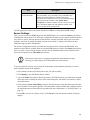
Note
The air flow sensor, integrated in the Sensor Pod 120 and in NetBotz 320 and 420
appliances, must accumulate up to 3 minutes of sensor data before it can provide
accurate air flow sensor readings. After the Sensor Pod or appliance is powered
on, air flow sensor data will appear as “N/A” until enough data has been collected.
To view sensor readings, simply select an item that includes sensors from the Navigation pane. The
Sensor Data pane is automatically updated to display the current reading being reported by any
sensors that are associated with the selected item, as well as the current alert status for each sensor. If
the selected item features a large number of sensors, the sensors may be divided into sensor sets. To
display all of the sensors included in the selected device select All Sensors from the Set drop-box. To
view only the sensors associated with a sensor set, select the desired sensor set from the Set dropbox. If a sensor is reporting an alert state, it’s table row will be colored red.
• To view a graph of all data that has been collected by a sensor in the last 60
minutes, click on the sensor’s current value in the Sensor Data pane. The
Action/Information pane automatically switches to the Graph view and
displays a graph of the data that has been collected from the selected sensor in
the past hour.
Note
• If you have selected an integrated camera, Camera Pod 120, or CCTV
Adapter Pod 120 from the Navigation pane, you can quickly view the image
being captured by that camera by clicking View Camera in the Sensor Data
pane. The Action/Information pane automatically switches to the Camera
View, with the selected camera pod image displayed.
Using Your Appliance
17
Basic View: Monitoring Appliances
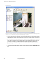
Viewing Camera Images
To view images being captured by any integrated camera or Camera Pod 120s or CCTV Adapter Pod
120s connected to the appliance, click on the Cameras tab in the Action/Information pane. Images for all
integrated or connected cameras are displayed in the Cameras panel, with one camera image displayed in
a larger, timestamped format. To switch the large format view to a different camera image, select the
thumbnail image that you wish to view.
You can also use the Cameras panel controls to specify the mode and dimensions of the large format
camera view, as well as the frequency with which the image is updated.
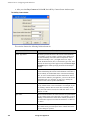
• To specify the dimensions of the image, select from the Mode drop box the desired mode (640x480
VGA is selected by default; other available modes are 160x120, 320x240, 800x600, 1024x768, and
1280x1024).
• To specify the frequency with which the image is updated, select from the Rate drop box the desired
rate (1 frame per second is selected by default; rates are also available ranging from 1 frame every
30 seconds to 30 frames per second depending on resolution).
• CCTV Adapter Pod 120s support only 160x120, 320x240, and 640x480.
Resolutions higher than 640x480 are available only from Camera Pod 120s.
Note
• Actual frame rate available from image processor depends on the resolution
and image quality of generated images. Maximum framerate of 30 frames per
second is available only at Normal Quality or lower and only at resolutions up
to 640x480. Maximum frame rate for 800x600, 1024x768, and 1280x1024 at
Normal Quality or lower is 10 frames per second. If you configure the Camera
Pod 120 to capture images in High Quality, the Maximum Frame Rate for
some resolutions changes: At 640x480 and lower resolution the maximum
frame rate drops from 30 frames per second to 20 frames per second. In
800x600 the maximum frame rate is unchanged (stays at 10 frames per
second). In 1024x768 and 1280x1024 the maximum frame rate drops from 10
frames per second to 8 frames per second. Also, the maximum frame rate
describes the maximum number of images that the camera imager is capable
of producing each second. The actual frame rate that will be visible in the
Basic View or Advanced View is largely dependent on the amount of
available bandwidth.
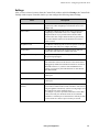
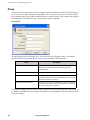
Viewing Alerts
To view alert conditions that are presently being reported by your appliance or any attached pods or
sensors:
1. Select the Alerts tab from the Action/Information pane.
2. Select from the Pods drop box the appliance or the pod or other device (such as RS232-based
sensors connected to the appliance using a USB-to-serial-port adapter) that you want to check for
currently active alert conditions. By default, the appliance is selected.
– If you want to view currently active alert conditions on the appliance and on all connected pods,
select All from the Pods drop box.
– If you want to view records of previously reported alert conditions that have since been resolved
check the Include Resolved Alerts check box. Previously resolved alerts can be stored on the
appliance for up to 24 hours. The period of time for which previously resolved alerts will be
available on the appliance is configured using the Advanced View.
18
Using Your Appliance
Basic View: Monitoring Appliances
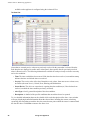
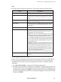
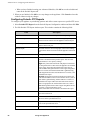
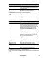
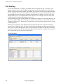
Alerts that are currently active or that were previously resolved for the item that is selected from the Pods
drop box are displayed in a table on the Alerts panel. Alert-specific data for previously resolved alerts is
shown in italics. The following information is available for each previously resolved or currently active
alert condition:
– Time: The time at which the alert occurred. If the alert has since been resolved, a second time
stamp indicates the time at which the alert was resolved.
– Severity: The severity value of the alert. Potential severity values, from most severe to least
severe, are Failure (the most severe), Critical, Error, Warning, and Information.
– Sensor/Device: The device or sensor that is reporting the alert condition (or, if the alert has been
resolved, on which the alert condition previously occurred).
– Alert Type: A brief, general description of the alert condition.
– Description: A detailed description of the specific conditions that caused the alert to be reported.
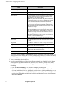
To view detailed information about a selected alert, click on the description of the alert. The Alerts panel
will update to show an Alert Details view. This view provides additional details about the selected alert,
including the current value being reported by the sensor that reported the alert, the external sensor port to
which the sensor is connected, the alert profile name that applies to this alert, and the alert ID value. To
return to the Alerts view, click on the View Alerts link in the upper-right hand corner of the Alert Details
view.
In addition to the previously mentioned details, alert-specific data -- including graphs of the sensor values
and camera images if appropriate -- is preserved on the appliance to aid in evaluating the cause and
resolution of alert conditions as long as space is available on the appliance. If additional alert-specific
data is available it will appear on the Alert Details view as a series of links in an Available Captured Data
table. To view the captured data, simply click on the description of the data. To return to the Alert Details
view click the Return to Alert Details link in the upper right-hand corner of the Additional Captured Data
view.
Saving Picture Sequences to Your System
If you have installed the BotzWare Premium Software Module 2.4 and an alert includes a picture
sequence as part of the alert event, you can save the picture sequence to your system as a M-JPEG AVI or
as a digitally signed M-JPEG AVI file. M-JPEG AVI files are motion picture files that can be played
using standard media player software (such as Windows Media Player). Signed files provide proof that
the generated images have not been tampered with or altered in any way, and are therefore more likely to
be admissible as evidence in legal proceedings.
To save a picture sequence as an M-JPEG AVI or as a Signed M-JPEG AVI, select an alert from the Alerts
view, select the picture sequence from Available Captured Data list for the alert, and then click on either
Get M-JPEG AVI or Get Signed M-JPEG AVI.
For information on how to verify that signed AVI files have not been tampered with, see “Verifying
Signed M-JPEG AVI Files” on page 199.
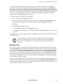
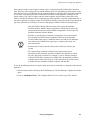
Viewing Maps
The Map View, available for use only on appliances for which the BotzWare Premium Software Module
2.4 has been purchased, enables you to view user-created maps that show the location of your NetBotz
appliances, pods, and sensors. The alert state of all devices shown on the Map View are indicated with
simple color coding (red indicates that an alert state currently exists, while green indicates that no alert
state is currently being reported by the sensor or device). The BotzWare Premium Software Module is
available as part of NetBotz Extended Warranty Coverage. For more information, contact your NetBotz
authorized reseller or the NetBotz support team).
Using Your Appliance
19
Basic View: Monitoring Appliances
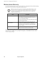
You can use the Basic View to view only previously created maps. To create, edit,
or delete a map you must use the Advanced View.
Note
To view a map using the Basic View, select the Maps tab in the Action/Information pane. The first
available map that is stored on the appliance is automatically loaded in to the Action/Information pane. If
there is more than one map stored on the appliance you can select additional map views from the Maps
drop box.
Once the map is loaded, the alert status of any appliances, pods, sensors, or other devices that have been
placed on the map can be observed by noting the color of the background of each device’s label box. If
the background is red then an alert state currently exists for that sensor or device. If the background is
green, then no alert state is currently being reported.
To view sensor readings for any device displayed in the Map view, simply select the device from the Map
view. The Sensor Data pane is automatically updated to display the current reading being reported by any
sensors that are associated with the selected item, as well as the current alert status for each sensor. If the
selected item features a large number of sensors, the sensors may be divided into sensor sets.
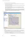
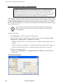
Viewing Graphs
To view a graph of the data collected by a single sensor that is connected to your appliance:
1. Select the Graphs tab in the Action/Information pane.
2. Select from the Pods drop box the pod or other device (such as a device being monitored using
Device Crawlers, or RS232-based sensors connected to the appliance using a USB-to-serial-port
adapter) that either includes the sensor you wish to view or to which the external sensor that you
wish to view is connected.
– Camera Pod 120s and CCTV Adapter Pod 120s include camera motion, door switch, speaker
plug, and microphone plug sensors.
– Integrated cameras (NetBotz 320 and 420 models only) include camera motion and door switch
sensors.
– Sensor Pod 120s and integrated Sensor Pods (NetBotz 320 and 420 models) include temperature,
humidity, dew point, air flow, and audio sensors, as well as up to 4 additional external sensors.
– Devices being monitored using Basic Device Crawlers report System/Status data, including
Online status, Ping RTT, SNMP System Uptime, as well as one additional sensor set for each
interface included in the device.
– Devices being monitored using Advanced Device Crawlers for which there is DDF-based data
will feature an additional Advanced Data sensor set that includes the sensor data collected by
Advanced Device Crawlers. The sensor data available from this sensor set is device-specific, but
may include items such as temperature, voltage, air flow, and so forth.
3. If necessary, select from the Set drop box the sensor set that includes the sensor that you want to
graph.
4. Select from the Sensors drop box the sensor for which the available data will be graphed. Only
sensors that are available on the device selected from the Pods drop box, and that are included in the
20
Using Your Appliance
Basic View: Monitoring Appliances
currently selected sensor Set (if applicable) will be listed in the Sensors drop box.
5. Select from the Graph Time drop box the period of time prior to the present for which data from the
selected sensor will be graphed. By default, all data available from the past 60 minutes will be
graphed. Up to 24 hours of data can be graphed, depending on sensor configuration.
Triggering Relay Outputs
If you have Output Relay Pod 120s or supported RS232-based output control devices connected to your
appliance and the currently logged in user account is authorized to trigger outputs, you can trigger
outputs using the Basic View. To trigger an output action, select from the Navigation pane the output
control device to which the relay-based device you want to trigger is connected. Then, locate the desired
relay in the list of relays located in the Sensor Readings pane. To trigger the relay, click the button that
corresponds to the relay.
Using Your Appliance
21
Basic View: Monitoring Appliances
22
Using Your Appliance
Basic View: Configuring Appliances
The Basic View is designed primarily for viewing the sensor data, camera images, and alert
conditions that are currently being reported by the appliance and the pods or sensors that are
connected to the appliance. The vast majority of appliance, pod, and sensor configuration must be
performed using the Advanced View interface. However, the Basic View does provide some limited
configuration capabilities to assist in initial appliance, pod, and sensor installation, when access to a
system capable of running the Advanced View application may not be convenient. All available
configuration tasks are performed using the Setup tab in the Actions/Information pane.
Configuring the Appliance
The only configuration task that can be performed on an appliance using the Basic View is specifying
a unique identification label for the appliance. This label will be used to uniquely identify the
appliance in the Basic View interface and in alert notifications associated with the appliance.
To specify a label for the appliance, select the appliance from the Pods drop box in the Setup panel.
Then, type in the Pods Label field the label that will be used to identify the appliance. When you have
finished typing in the label value, click Update to save the label value for your appliance.
Configuring Camera Pod 120s and Integrated Cameras
The only configuration task that can be performed on a Camera Pod 120 or integrated camera
(NetBotz 320/420 models only) using the Basic View is specifying a unique identification label for
the Camera Pod 120 or integrated camera. This label will be used to uniquely identify the Camera
Pod 120 or integrated camera in the Basic and Advanced View interfaces and in alert notifications
associated with the camera.
To specify a label for the Camera Pod 120 or integrated camera, select the Camera Pod 120 or
integrated camera from the Pods drop box in the Setup panel. Then, type in the Pods Label field the
label that will be used to uniquely identify the camera. When you have finished typing in the label
value, click Update to save the label value.
Configuring CCTV Adapter Pod 120s
The only configuration task that can be performed on a CCTV Adapter Pod 120 using the Basic View
is specifying a unique identification label for the CCTV Adapter Pod 120. This label will be used to
uniquely identify the CCTV Adapter Pod 120 in the Basic and Advanced View interfaces and in alert
notifications associated with the CCTV Adapter Pod 120.
To specify a label for the CCTV Adapter Pod 120, select the CCTV Adapter Pod 120 from the Pods
drop box in the Setup panel. Then, type in the Pods Label field the label that will be used to uniquely
identify the CCTV Adapter Pod 120. When you have finished typing in the label value, click Update
to save the label value for your CCTV Adapter Pod 120.
Configuring Sensor Pod 120s
The only configuration tasks that can be performed on a Sensor Pod 120 using the Basic View are
specifying a unique identification label for the Sensor Pod 120, specifying the type of external
sensors that are attached to each of the external sensor ports on the Sensor Pod 120, and providing a
unique identification label for each external sensor. These labels will be used to uniquely identify the
Sensor Pod 120 and the external sensors in the Basic and Advanced View interfaces and in alert
notifications associated with the Sensor Pod 120 or external sensors.
Using Your Appliance
23
Basic View: Configuring Appliances
To specify a label for the Sensor Pod 120, select the Sensor Pod 120 from the Pods drop box in the Setup
panel. Then, type in the Pods Label field the label that will be used to uniquely identify the Sensor Pod
120. When you have finished typing in the label value, click Update to save the label value for your
Sensor Pod 120.
To specify the type of external sensors that are connected to each of the external sensor ports on your
Sensor Pod 120, and to specify a label for each of these sensors, select the Sensor Pod 120 to which the
external sensors are connected from the Pods drop box in the Setup panel. Then, select from the drop box
beside the External Sensor Port ID the specific external sensor that is connected to each port. If desired,
type in the Port Label field a label that will be used to uniquely identify the Sensor Pod 120 and port to
which it is connected. When you have finished, click Update to save the label value for your Sensor Pod
120.
Configuring Integrated Sensor Pods (NetBotz 320/420 Only)
The only configuration tasks that can be performed on integrated Sensor Pods (included with NetBotz
320/420 models only) using the Basic View are specifying the type of external sensors that are attached to
each of the external sensor ports on the NetBotz appliance and providing a unique identification label for
each external sensor. These labels will be used to uniquely identify the external sensors in the Basic and
Advanced View interfaces and in alert notifications associated with the external sensors.
To specify the type of external sensors that are connected to each of the external sensor ports on your
NetBotz appliance, and to specify a label for each of these sensors, select the integrated Sensor Pod from
the Pods drop box in the Setup panel. Then, select from the drop box beside the External Sensor Port ID
the specific external sensor that is connected to each port. If desired, type in the Port Label field a label
that will be used to uniquely identify the sensor and port to which it is connected. When you have
finished, click Update to save the label value.
Configuring 4-20mA Sensor Pods
Before continuing, be sure that you have correctly connected the 4-20mA Sensor
Pod to your appliance.
Note
The only configuration tasks that can be performed on a 4-20mA Sensor Pod using the Basic View are
specifying a unique identification label for the 4-20mA Sensor Pod, specifying the type of 4-20mA
sensors that are attached to each of the ports on the 4-20mA Sensor Pod, and providing a unique
identification label for each 4-20mA sensor. These labels will be used to uniquely identify the 4-20mA
Sensor Pod and the 4-20mA sensors in the Basic and Advanced View interfaces and in alert notifications
associated with the 4-20mA Sensor Pod or 4-20mA sensors.
To specify a label for the 4-20mA Sensor Pod, select the 4-20mA Sensor Pod from the Pods drop box in
the Setup panel. Then, type in the Pods Label field the label that will be used to uniquely identify the 420mA Sensor Pod. When you have finished typing in the label value, click Update to save the label value
for your 4-20mA Sensor Pod.
To specify the type of 4-20mA sensors that are connected to each of the sensor ports on your 4-20mA
Sensor Pod, and to specify a label for each of these sensors, select the 4-20mA Sensor Pod to which the 420mA sensors are connected from the Pods drop box in the Setup panel. Then, select from the drop box
beside the External Sensor Port ID the specific 4-20mA sensor that is connected to each port. If desired,
type in the Port Label field a label that will be used to uniquely identify the 4-20mA Sensor Pod and port
to which it is connected. When you have finished, click Update to save the label value for your 4-20mA
Sensor Pod.
24
Using Your Appliance
Basic View: Configuring Appliances
Configuring Output Relay Pod 120s
Before continuing, be sure that you have correctly connected the Output Relay
Pod 120 to your appliance.
Note
The only configuration tasks that can be performed on a Output Relay Pod 120 using the Basic View are
specifying a unique identification label for the Output Relay Pod 120, specifying the output type that will
be used for each relay, and providing a unique identification label for each relay.
To configure an Output Relay Pod 120 from the Basic View:
1. Click on the Setup button.
2. Select the output control device you wish to configure from the Pods drop-box. A list of available
output ports on the selected device appears.
3. Select from the Output Type Configured drop-box beside each port the output control action you
want to assign to the corresponding port. The following output types are available by default:
– None: No output action is associated with this port.
– One-Second Button (NC): When activated, a normally closed (NC) relay is switched to an open
state for 1 second, and then switched back to closed.
– One-Second Button (NO): When activated, a normally open (NO) relay is switched to a closed
state for 1 second, and then switched back to open.
– Switch (NC): When activated, a normally closed (NC) relay is switched to an open state.
– Switch (NO): When activated, a normally open (NO) relay is switched to a closed state.
– Ten-Second Button (NC): When activated, a normally closed (NC) relay is switched to an open
state for 10 seconds, and then switched back to closed.
– Ten-Second Button (NO): When activated, a normally open (NO) relay is switched to a closed
state for 10 seconds, and then switched back to open.
If you have used the Advanced View to define custom output types, your custom output types will
be available from this list as well.
4. Type in the Port Label field the label that will be used to uniquely identify the device connected to
output control device port.
5. Click Update to save your output device settings.
Configuring Power Control Pods
You can use the Basic View to specify the Power Control Pod model that you have connected to your
appliance using a USB-attached serial port device or hub. You can also specify a unique identification
label for the each Power Control Pod, specify the output type that will be used for each outlet on the pod,
and providing a unique identification label for each outlet.
To specify the Power Control Pod model that is connected to each serial port:
1. Click on the Setup button.
2. Select the appliance from the Pods drop box in the Setup panel.
3. Select from the Device Type Installed drop box beside each identified serial port the specific Power
Using Your Appliance
25
Basic View: Configuring Appliances
Control Pod model (110, 115, 230, or 235) that is connected to that port.
4. Click Update to save your serial device settings.
To specify the output type that will be assigned to each outlet on your Power Control Pod and to specify a
unique label for each outlet:
1. Click on the Setup button.
2. Select the Power Control Pod you wish to configure from the Pods drop-box. A list of available
outlets (1 outlet for Power Control Pod 110s and 230s, 5 outlets for Power Control Pod 115s and
235s) on the selected pod appears.
3. Select from the Output Type Configured drop-box beside each outlet the output control action you
want to assign to the corresponding port.
Note
When configuring output types on Power Control Pods, the “closed” relay state
causes the circuit on the outlet to be closed and the power to be “on.” The “open”
relay state opens the circuit on the outlet and causes the power to be “off.” For
example, selecting a Ten-Second Button (NC) output type would, when
activated, “open” the outlet and interrupt the power supplied to the device that is
connected to the outlet for 10 seconds, after which the outlet would be “closed,”
restoring power to the device.
The following output types are available by default:
– None: No output action is associated with this port.
– One-Second Button (NC): When activated, a normally closed (NC) relay is switched to an open
state for 1 second, and then switched back to closed.
– One-Second Button (NO): When activated, a normally open (NO) relay is switched to a closed
state for 1 second, and then switched back to open.
– Switch (NC): When activated, a normally closed (NC) relay is switched to an open state.
– Switch (NO): When activated, a normally open (NO) relay is switched to a closed state.
– Ten-Second Button (NC): When activated, a normally closed (NC) relay is switched to an open
state for 10 seconds, and then switched back to closed.
– Ten-Second Button (NO): When activated, a normally open (NO) relay is switched to a closed
state for 10 seconds, and then switched back to open.
If you have used the Advanced View to define custom output types, your custom output types will
be available from this list as well.
4. Type in the Port Label field the label that will be used to uniquely identify the device connected to
output control device port.
5. Click Update to save your output device settings.
Testing Device Power-On Behavior
Before connecting a device to a Power Control Pod, be sure to first test the device to ensure that when
power is restored to the device it powers up without requiring user interaction (such a pressing a power
button, for example).
26
Using Your Appliance
Basic View: Configuring Appliances
To test the device’s power-on behavior, simply plug it directly into a standard power outlet. If the device
power on fully without requiring additional interaction it can be used properly with the Power Control
Pod. However, if you determine that the restoring power to the device does not enable the device to return
to a fully operational state then you may need to update or modify the device (such as changing power
control options in the BIOS of a server or workstation, for example) to ensure that the device will work
properly when used with your Power Control Pod.
Configuring Serial and RS232-Based Sensors
You can use the Basic View to specify which supported serial communications device you have installed
in the PC Card slot of your appliance, or to specify which RS232-based sensors (such as a NMEAcompliant GPS receiver or a supported RAE Systems device) you have connected to your appliance using
a USB-attached serial port device or hub. You can also specify a label for each serial port.
Note
RAE Systems device support is available only with the additional purchase of a
RAE Systems Sensors Option license. If you are configuring a RAE Systems
device be sure to use the Advanced View License Keys task (see “License Keys”
on page 114) to activate RAE Systems device support on your appliance. For
more information on RAE Systems Sensors Option see “Add-Ons: RAE Systems
Sensors Option” on page 181.
To specify the serial communications device or sensor that is connected to each serial port, select the
appliance from the Pods drop box in the Setup panel. Then, select from the Device Type Installed drop
box beside each identified serial port the device that is connected to that port. When you have finished,
click Update to save your serial device settings.
To specify a label for each serial port, select the appliance from the Pods drop box in the Setup panel.
Then, type in the Port Label beside each identified serial port field the label that will be used to uniquely
identify this serial port. When you have finished, click Update to save your serial device settings.
Using Your Appliance
27
Basic View: Configuring Appliances
28
Using Your Appliance
About the Advanced View
The Advanced View is a stand-alone Java application that enables you to monitor and configure your
appliance and any Camera Pod 120s, Sensor Pod 120s, CCTV Adapter Pod 120s, Output Relay Pod
120s, 4-20mA Sensor Pods, external sensors, or supported RS232-based sensors that are connected to
the appliance. Using the Advanced View, you can quickly and easily view the current sensor readings
being reported by any pods, supported RS232-based sensors, external sensors connected to integrated
external sensor ports (NetBotz 320/420 only) or Sensor Pod 120s, 4-20mA sensors connected to a 420mA Sensor Pod, and devices being monitored using Device Crawlers, view a list of all currently
active and recently resolved alert conditions, and view the images currently being captured by any
Camera Pod 120s or CCTV Adapter Pod 120s connected to your appliance. In addition, the
Advanced View provides complete appliance and pod configuration functionality, enabling you to
perform all of the tasks necessary for complete management of all of your appliances and pods.
The Advanced View.
Using Your Appliance
29
About the Advanced View
Adding Appliances
Before you can use the Advanced View to manage an appliance you must first add the appliance’s IP
address or hostname to the Appliance list. To add an appliance to the Appliance list:
1. Click Add Appliance. The Add Appliance window opens.
2. Type in the IP Address or Hostname field the IP address or hostname of the appliance.
The Add Appliance window.
3. Type in the Port field the TCP port through which you will communicate with this appliance.
4. Enable SSL encryption (optional). To use SSL encryption to communicate with this appliance,
check the Use SSL check box.
5. Click OK to add the appliance to the Appliance list.
Once you have added an appliance to the Appliance list, the Advanced View will automatically attempt
to load data from the appliance into the Advanced View. Once an appliance has been added to the
Appliance list, you can quickly navigate to it by selecting the appliance’s address or hostname from the
Appliance list. Note that if you specified Use SSL when adding the appliance then “(SSL”) will appear
in the selection list beside the appliance’s IP address or hostname.
Accessing and Logging Into the Appliance Using the Advanced
View
Once you have added an appliance to the Appliance list, select the appliance from the Appliance list to
attempt to access it.
• If the appliance’s Guest account is configured with a Sensor (No Cameras), Sensor, Application,
or Administrator privilege set (see “Users” on page 137) you will automatically be granted access
to the appliance and you will be able to view the Advanced View panes that are permitted by the
privilege set (see “Advanced View Panes Accessible by Privilege Set” on page 31). If you have a
user account on the appliance with greater privileges than those allowed to guests, click the Logon
button at the top of the Advanced View interface and provide your User ID and Password.
• If the Guest account is configured with no privileges (privilege set of None), you will be prompted
to provide a User ID and Password to access the appliance. Once you have logged in, you will be
able to view the Advanced View panes that are permitted by the privilege set assigned to your user
account (see “Advanced View Panes Accessible by Privilege Set” on page 31).
30
Using Your Appliance
About the Advanced View
Advanced View Panes Accessible by Privilege Set
The Advanced View panes that are accessible, depending on the privilege set of the account that is logged
in and using the Advanced View, are:
Privilege Set
Accessible Panes
Administrator
Cameras View, Graphs View, Alerts View, Configuration,
and About panes.
Application
Cameras View, Graphs View, Alerts View, and About panes.
Sensor
Cameras View, Graphs View, and About panes.
Sensor (No Cameras)
Graphs View and About panes.
None
Does not permit access to any appliance features.
Interface Navigation
The Advanced View interface is divided into three primary regions: The Navigation Pane, the Sensor
Data Pane, and the Action/Information Pane.
The Navigation Pane
Located in the upper-left corner of the interface, the Navigation pane is used to select your appliance;
pods that are attached to or integrated with the appliance; other managed and monitored objects, such as
RS232-based sensors or output control devices that are being monitored using Device Crawlers (for more
information, see “Device Crawlers” on page 77); or Alerting Sensors, which is a “virtual device” that
presents a dynamic overview of all currently alerting sensors as reported by the appliance as well as pods
and other devices connected to the appliance. The device selected from the Navigation Pane filters the
contents of the Sensor Data Panel. To view information about an item that appears in the Navigation pane
you must first select it.
As pods are connected to your appliance, they will automatically appear in the Navigation pane. Newly
added pods will be labeled by their pod type (for example, Sensor Pod, Camera Pod, CCTV Pod, or
Output Relay Pod) and their serial number. Once a pod has been added, you can change its label using
either the Camera Pods, Sensor Pods, or Output Control tasks.
Note
In addition to 1 docked Camera Pod or integrated camera and 1 docked or
integrated Sensor Pod, the Navigation pane can contain only up to 4 unique
tethered Camera Pod or CCTV Adapter Pod entries, up to 16 unique tethered
Sensor Pod entries, and up to 4 unique tethered Output Relay Pod entries (pods or
devices that appear in folders as well as in the main appliance tree count as a
single entry. For information about folders, see “Using Folders” on page 32).
If you connect a pod and then disconnect it, its entry will remain in the Navigation pane, but will be
“grayed out.” If your reconnect a previously disconnected pod, its Navigation pane entry will become
active again. However, if you have reached the maximum number of pod-specific entries in the
Navigation pane (5 Camera Pods/CCTV Adapter Pods, 17 Sensor Pods, 4 Output Relay Pods) including
“grayed out” entries, additional pods will not appear in the Navigation pane until you delete a pod entry
of the same type from the list.
Also, note that the maximum number of pod-specific entries in the Navigation pane (5 Camera Pods/
CCTV Adapter Pods, 17 Sensor Pods, 4 Output Relay Pods) is greater than the maximum number of
Camera and Sensor Pods that can be used by any NetBotz appliance other than a NetBotz 500.
Using Your Appliance
31
About the Advanced View
Using Folders
If desired, you can create folders in the Navigation Pane. Folders enable you to create virtual groups of
pods and devices that can be used to simplify organization of your various pods and devices for
management purposes.
By default, the Navigation Pane does not feature any folders. Instead, the Navigation Pane presents a
selectable list of all pods and devices that are associated with the appliance. When you add a folder, you
include one or more pods or devices that are associated with the appliance in the folder as well. Devices
that are included in a folder continue to be listed in the selection list as well, and an individual pod or
other device can be included in multiple folders.
Folders offer a convenient way to organize devices into user-specified groupings. Furthermore, when a
folder is not expanded, the color of the folder represents the current “worst” alert state of any device that
exists within the folder. for example, if you create a folder that contains all of the devices in a specific
building and one of those devices enters an alert state, the name of the folder will turn red to indicate that
one of the devices in the folder is alerting.
Folders can be created, modified, or deleted only when using the Advanced View. However, any folders
that are created using the Advanced View will be visible in the Navigation Pane of the Basic View.
To create or modify a folder:
1. Right-click on the background of the Navigation pane (not on a device) and then select Add Folder.
To modify a previously created folder, right-click on the folder and select Modify Folder.
2. The Add Folder window appears. Type in the Folder Name field a name for this folder.
3. To add devices, select from the Available Enclosures selection list one or more devices that you
want to include in this folder, and then click the “right arrow” (>) button to move the selected
devices into the Selected Enclosures selection list.
4. To remove devices, select from the Selected Enclosures selection list one or more devices that you
do not want to include in this folder, and then click the “left arrow” (<) button to move the selected
devices into the Available Enclosures selection list.
5. Click OK to save the folder.
To delete a previously created folder, right-click on the folder and click Delete Folder.
Locking a Navigation Pane Selection
If desired, you can lock the Navigation pane so that only a specific device is selected.Once the Navigation
pane is locked, you will not be able to select any other devices from the Navigation pane until you unlock
the pane. Once you have locked the Navigation pane, the Advanced View will automatically start with the
pane in the locked state.
To lock the pane to a specific device, first select the desired device. Then, right-click on the device and
select Lock selection. To unlock the pane, right-click on any device in the Navigation pane and select
Lock selection.
The Sensor Data Pane
Located in the lower-left hand corner of the interface, the Sensor Data pane displays the current readings
and alert status of any sensors that are associated with the item that is currently selected in the Navigation
pane. If the selected item is an output relay device (such as a Output Relay Pod 120 or a supported
RS232-based relay output device) then the current state of the relay is displayed.
32
Using Your Appliance
About the Advanced View
If the selected item features a large number of sensors, the sensors may also be divided into sensor sets.
Sensor sets enable you to filter the contents of the Sensor Data pane to display only sensors that are
associated with a specific interface or portion of the selected device. To display all of the sensors included
in the selected device select All Sensors from the Set drop-box. To view only the sensors associated with
a sensor set, select the desired sensor set from the Set drop-box.
Note
The air flow sensor, integrated in the Sensor Pod 120, must accumulate up to 3
minutes of sensor data before it can provide accurate air flow sensor readings.
After the Sensor Pod is powered on, air flow sensor data will appear as “N/A”
until enough data has been collected.
The Action/Information Pane
Located on the right-hand side of the interface, the Action/Information pane contains a series of buttons
that enable you to view information and perform configuration tasks on your appliance and pods. Each
button, when selected, presents a different panel in the Action/Information pane. The following panels are
available from the Action/Information pane:
• Camera View: Displays the images currently being captured by any integrated camera (NetBotz
320 and 420 only) or Camera Pod 120s or CCTV Adapter Pod 120s connected to the appliance.
Also enables you to listen to an audio stream from a selected Camera Pod 120 or CCTV Adapter
Pod 120. If relay outputs are associated with any of your camera pods (“Associating Relays or
Switches with Integrated Cameras and Camera Pods” on page 68) then buttons that correspond to
each associated switch or relay will appear on the camera image to which they correspond.
• Alerts View: Displays alerts that are currently being reported by the appliance, any pods that are
connected to the appliance, or any devices that are being monitored using Device Crawlers. Alerts
that have recently occurred, but which have been resolved, can be shown as well.
• Maps View: Displays maps that have been configured for use with this appliance. The alert state of
all devices shown on the Map View are indicated with simple color coding (red indicates that an
alert state currently exists, while green indicates that no alert state is currently being reported by the
sensor or device). The Map View is available for use only on appliances for which the BotzWare
Premium Software Module 2.4 has been purchased.The BotzWare Premium Software Module is
available as part of NetBotz Extended Warranty Coverage. For more information, contact your
NetBotz authorized reseller or the NetBotz support team.
• Graph View: Displays a graph of up to 24 hours of environmental data that has been collected from
any sensor that is connected to the NetBotz appliance (including sensors that are built into pods,
external sensors connected to Sensor Pod 120s, devices that are being monitored using Device
Crawlers, RS232-based sensors that are connected to your appliance using a USB-to-serial-port
adapter, and relay-based devices connected to Output Relay Pod 120s).
• Configuration: Enables you to access the configuration tasks that are available for your appliance,
as well as any pods that are connected to the appliance or external sensors that are connected to your
pods. Also enables you to configure Device Crawlers to monitor additional devices.
• About: Displays information about your appliance and all connected pods.
Using Your Appliance
33
About the Advanced View
Advanced View Menus
The Advanced View features the following pull-down menus, located at the top of the interface:
• File: Use the selections available from the File pull-down menu to Add appliances to or Remove
appliances from the Appliance selection pull-down and to Exit the Advanced View application.
• Edit: Use the selections available from the Edit pull-down menu to Cut, Copy, Paste, and Delete
text (when possible), and to configure Client Preferences. For more information on editing Client
Preferences, see “Editing Client Preferences” on page 35.
• Tools: Use the selections available from the Tools pull-down menu to:
– View Messages (information generated by the Advanced View for logging and debugging
purposes)
– Put the appliance in NetBotz Central Post-only Mode. This mode is designed for use only with
appliances that are located behind a firewall that does not permit NetBotz Central appliances to
access the appliances directly. For more information, see “Using NetBotz Central Post-Only
Mode” on page 34.
– View the Appliance Log (information regarding appliance functionality that is generated and
logged according to the Log settings. For more information, see “Log” on page 116)
– Change the Root Password (the password needed to access the appliance when communicating
with it using the serial port. For more information, see your About Your Appliance booklet)
– Reboot the appliance
Note
The NetBotz Central Post-Only Mode, Appliance Log, Change Root Password,
and Reboot Appliance menu selections are available only to user accounts that
have administrator privileges. For more information see “Users” on page 137.
– Window: Use the selections available from the Window pull-down menu to launch a New
Window (creating an additional instance of the Advanced View), or to switch between multiple
Advanced View windows that are currently running.
– Help: Use the selections available in the Help pull-down menu to access information About the
Advanced View and to access the online Help system.
Using NetBotz Central Post-Only Mode
If you will be using NetBotz Central to monitor and manage your appliance, and the appliance is located
behind a firewall, NetBotz Central may not be able to communicate directly with the appliance. Placing
the appliance in NetBotz Central Post-Only Mode will cause the appliance to post all monitoring data to a
specified NetBotz Central appliance at a user-specified interval. If desired, SSL encryption can be used
for secure posting of data.
To use NetBotz Central Post-Only Mode:
1. Start the Advanced View and log into the appliance using a User account that has administrator
privileges.
2. Select Advanced > NetBotz Central Post-Only Mode from the Tools pull-down menu. The
NetBotz Central Post-Only Mode Configuration window opens.
3. Specify an Interval between posts value. This determines how frequently the appliance will post
34
Using Your Appliance
About the Advanced View
data to the specified NetBotz Central appliance.
4. Specify the NetBotz Central IP Address/Hostname. This is the IP address or hostname of the
NetBotz Central appliance to which data will be posted.
5. Specify the Port on which the NetBotz Central appliance is configured to receive HTTP post data.
Default value is 80.
6. If desired, select an SSL Option. You can select Do not use SSL, Require SSL - No Verification,
Require SSL - Verify Certificate, or Require SSL - Verify Certificate and Hostname.
7. Click OK to save your settings.
Editing Client Preferences
The Advanced View features a number of user-configurable client preferences. Unlike other
configuration tasks that you perform using the Advanced View, changes to client preferences apply only
to the look, feel, and functionality of the Advanced View application on your client system. These
settings are saved on your client system, not on your appliance.
To edit your client preferences, select Client Preferences from the Edit pull-down menu. Client
preferences are divided into three categories:
• Appearance
• General
• Network
The Client Preferences window.
Appearance Preferences
To edit your client’s Appearance settings, open the Client Preferences interface and then select
Appearance from the Categories selection list. You can configure the following appearance settings:
Field
Look and Feel
Description
Controls the basic appearance of the interface and the interface
controls (buttons, menus, drop boxes, etc.). You can choose
CDE/Motif, Kunststoff, Metal, or Windows.
Using Your Appliance
35
About the Advanced View
Field
Description
Toolbar
Controls that specify the look and feel of the buttons in the
Action/Information pane. You can:
• Specify the button content:
– If you want the buttons to include text, check the
Text check box.
– If you want the buttons to include icons, check
the Icons check box.
– To include both text and icons, check both check
boxes
• Specify icon size:
– If icons are selected, specify whether the icons
should be Small or Large.
Note: You can also change the button appearance by rightclicking in the button bar and selecting/deselecting button
appearance options from the pop-up menu.
When you are finished specifying client Appearance preferences, click OK to save your settings and
close the Client Preferences window.
General Preferences
To edit your client’s General settings, open the Client Preferences interface and then select General from
the Categories selection list. You can configure the following general settings:
Field
Description
Browser Location
The fully qualified path and executable name of the web
browser program that will be used to display online help. You
can use the Browse... button to navigate to the drive and
directory that contains your web browser executable if desired.
Restore minimized window on new
alerts check box
If this option is enabled and the Advanced View window is
running but minimized, the Advanced View will be maximized
automatically when any alert condition occurs.
Use non-default local time display
Use this option to force the Advanced View to display time
using a 12-hour or 24-hour clock, regardless of the default
clock type that is specified by the appliance’s Region settings.
When you are finished specifying client General preferences, click OK to save your settings and close the
Client Preferences window.
36
Using Your Appliance
About the Advanced View
Network Preferences
To edit your client’s General settings, open the Client Preferences interface and then select General from
the Categories selection list. You can configure the following general settings:
Field
Description
Connection Timeout
Type in this field the amount of time that the Advanced View
should wait when attempting to connect to an appliance before
giving up.
Proxy Hostname and Port
Type in these fields the host name or IP address of the Proxy
server (if the client system uses a Proxy server for e-mail,
HTTP Posts, and other outbound communications) and the IP
port number used to connect to the Proxy server (typically
1080, and must be between 1 and 65535).
When you are finished specifying client Network preferences, click OK to save your settings and close
the Client Preferences window.
Performing Configuration Tasks
The Configuration panel is divided into two areas: Pod/Sensors Settings, and Appliance Settings. Each
area features a number of icons that represent the configuration tasks that you can perform. To perform a
specific configuration task you simply double-click on the appropriate icon.
Pod and Alert Settings Tasks
The tasks available from the Pod/Sensors Settings portion of the panel enable you to configure the pods
and sensors that are connected to your appliance and to configure the alert actions and policies that will
be used when alerts are reported by your sensors. It also features the Device Crawlers task, which enables
you to configure your appliance to monitor SNMP target devices on your network. The following tasks
are available from the Pod/Sensors Settings portion of the Configuration panel:
• Alert Action: Use the Alert Action task to configure specific alert notification actions that will be
taken by the appliance in response to alert conditions. Alert actions specify a notification method
(such as sending e-mail or posting to web server) and provide the necessary information to direct
the alert notification to the specified recipient (such as e-mail addresses or the address of your web
server).
• Alert Profile: Use the Alert Profile task to customize your appliance’s alert notification policy. The
alert notification policy determines which alert actions are taken in response to alert conditions,
when those actions are taken, and how often they are repeated
• Camera Pods: Use the Camera Pods task to configure any integrated camera (NetBotz 320 and
420 only) or any Camera Pod 120s or CCTV Adapter Pod 120s that are connected to your
appliance. You can specify labels for each of your pods, set sensor thresholds, specify the visual
mode use by the camera, set image capture settings, configure the camera motion sensor, and apply
motion masks to the camera motion sensor. This task will be available only if your appliance
features an integrated camera or if one or more Camera Pod 120s or CCTV Adapter Pod 120s are
connected to your appliance.
• Device Crawlers: Use Device Crawlers to monitor individual remote SNMP targets (such as
servers, routers, and switches) for critical status information, enabling you to identify and resolve
problems faster. With Basic Device Crawlers (included with your appliance), you can configure
your appliance to periodically check the operating condition of up to 48 SNMP targets. If any
Using Your Appliance
37
About the Advanced View
operational difficulties are noted on a monitored target the appliance can generate an alert
notification, enabling you to quickly address the problem. Advanced Device Crawlers (a license
key-based add-on application, available for purchase separately) extends the capabilities of Basic
Device Crawlers to provide far more detailed device-specific information and to enable OIDspecific monitoring and alerting.
• IPMI Devices: Use the IPMI Devices task to add network-attached, Intelligent Platform
Management Interface-enabled devices to the list of devices that are monitored by your NetBotz
appliance.
• Output Control: Use the Output Control task to configure any output control devices (such as
Output Relay Pod 120s or Power Control Pods) that are connected to your appliance. You can
specify labels for each of your pods, set relay thresholds, and configure the external relay ports on
the Output Relay Pod 120 and power outlets on the Power Control Pod. This task will be available
only if one or more Output Relay Pod 120s or Power Control Pods are connected to your appliance.
• Periodic Reports: Use the Periodic Reports task to configure your appliance to generate sensor
reading reports and deliver them to e-mail recipients, HTTP servers, or FTP servers on a userspecified schedule.
• Sensor Pods: Use the Sensor Pods task to configure any Sensor Pod 120s that are connected to
your appliance or Sensor Pods that are integrated with your appliance (NetBotz 320 and 420 models
only). You can specify labels for each of your pods, set sensor thresholds, and configure the external
sensor ports integrated with NetBotz 320 or 420 appliances as well as those on Sensor Pod 120s. If
you have connected a Wireless Receiver 120 to your appliance, you can also use the Sensor Pods
task to configure thresholds for your wireless sensors. This task will be available only if one or more
Sensor Pod 120s are connected to or integrated with your appliance.
• Wireless Sensor Discovery: Use the Wireless Sensor Discovery task to specify the discovery
settings that will be used when detecting the presence of wireless sensors. This task will be available
only if a Wireless Receiver 120 is connected to your appliance.
38
Using Your Appliance
About the Advanced View
For detailed descriptions of all of the configuration tasks available from the Pod/Sensors Settings portion
of the configuration panel, see “Advanced View: Configuring Pods and Alerts” on page 59.
The Configuration View.
Using Your Appliance
39
About the Advanced View
Appliance Settings Tasks
The tasks available from the Appliance Settings portion of the panel enable you to configure your
appliance. The following tasks are available from the Appliance Settings portion of the Configuration
panel:
• Backup: Use the Backup task to save your appliance configuration to a password-protected,
encrypted file.
• Clock: Use the Clock task to view or change the date and time that are configured on the appliance
internal clock, or to configure your appliance to obtain and synchronize its clock settings from an
NTP server.
• DNS: Use the DNS task to view or change the appliance DNS settings.
• E-Mail: Use the E-mail task to specify the e-mail servers that will be used to deliver any e-mailed
alert notifications.
• External Storage: Use the External Storage task to configure your appliance to store data on the
optional Extended Storage System (sold separately) or a network attached storage device (a
Windows share or an NFS mount).
• IP Filter: Use the IP Filter task to limit access to your appliance to only specified IP addresses or IP
address-ranges.
• License Keys: Use the License Keys task to activate or deactivate available license key-enabled
applications that are available for use on this appliance.
• Location: Use the Location task to configure additional sensor-specific location information that
will also be included in alert notifications generated by the appliance.
• Log: Use the Log task to specify what events will be stored and displayed in the Appliance Log, and
to configure the appliance to post log data to a remote syslog server.
• Network Interfaces: Use the Network Interface task to view or change the network settings for
each network interface that is available on the appliance. By default there is only 1 network
interface (for the integrated Ethernet controller). However, if you install a wireless network adapter
in the PC Card slot then this additional network interface is configured using this task as well.
• PPP/Modem: Use the PPP/Modem task to configure PPP communications settings. This task will
be available only if a supported USB or PC Card modem has been connected to or installed in your
40
Using Your Appliance
About the Advanced View
appliance and you have used the Serial Devices task to specify the modem that is associated with
the appropriate serial port.
• Proxy: Use the Proxy task to provide the necessary settings to allow the appliance to utilize an
HTTP, Socks V4, or V5 Proxy Server.
• Region: Use the Region task to specify the region in which the appliance is being used, to specify
the time zone, and to configure the appliance clock to report time using a 12- or 24-hour clock.
• Pod Sharing: Use the Pod Sharing task to configure your NetBotz 500 series appliance to host
“virtual pods.” Using Pod Sharing, your NetBotz 500 can connect with and receive data directly
from devices integrated with or connected to NetBotz 320, 420 or 500s in your network.
• Restore: Use the Restore task to restore your NetBotz 500 configuration using a configuration file
created using the Backup task.
• Serial Devices: Use the Serial Devices task to specify the types of serial port-based sensors or
devices (such as modems) you have connected to your appliance.
• SMS: Use the SMS task to view or change the SMS (Short Messaging Service) settings used by
your appliance. This task will be available only if a supported PC Card modem that supports SMS
functionality has been installed in your appliance and you have used the Serial Devices task to
specify the modem that is associated with the appropriate serial port.
• SNMP: Use the SNMP task to view or change the appliance’s SNMP settings.
• SSL: Use the SSL task to install an SSL certificate for use with SSL-encrypted communication
between clients using the Advanced View application and the appliance.
• Upgrade: Use the Upgrade task to display the currently installed BotzWare version level and to
update the BotzWare on your appliance.
• Users: Use the Users task to configure user accounts for personnel that will be permitted access to
your appliance, or to modify the Administrator and Guest account settings.
• Web Server: Use the Web Server task to view or change the IP ports through which the appliance
web server performs HTTP and HTTPS web server communications.
For detailed descriptions of all of the configuration tasks available from the Appliance Settings portion of
the configuration panel, see “Advanced View: Configuring Appliances” on page 105.
Using Your Appliance
41
About the Advanced View
42
Using Your Appliance
Advanced View: Monitoring Appliances
The Advanced View enables you to easily view sensor readings, view camera images, graph collected
sensor data, and view currently active and resolved alert conditions. If you have purchased NetBotz
Extended Warranty Coverage and have added the BotzWare Premium Software Module 2.4 license
key to your appliance you can also create, view, and delete maps for use in the Map view.
You can use the Advanced View to view the monitored value and alert status of any sensor that is
currently connected to the appliance. Sensors are included in the Camera Pod 120 (camera motion,
door switch, microphone plug, speaker plug) and Sensor Pod 120 (air flow, temperature, humidity,
dew point, audio, as well as up to 4 external sensors). Additionally, Basic Device Crawlers, add-on
devices (such as RS232-based sensors) and add-on applications (such as Advanced Device Crawlers)
provide additional items in the Navigation pane, with each monitored device providing additional
sensor data.
To view sensor readings, simply select an item that includes sensors from the Navigation pane. The
Sensor Data pane is automatically updated to display the current reading being reported by any
sensors that are associated with the selected item, as well as the current alert status for each sensor. If
the selected item features a large number of sensors, the senors may be divided into sensor sets. To
display all of the sensors included in the selected device select All Sensors from the Set drop-box. To
view only the sensors associated with a sensor set, select the desired sensor set from the Set dropbox. If a sensor is reporting an alert state, it’s table row will be colored red.
Viewing Camera Images
To view images being captured by any Camera Pod 120s or CCTV Adapter Pod 120s connected to
the appliance, click on the Camera View tab in the Action/Information pane. Images for all
connected camera pods are displayed in the Camera View panel, with one camera image displayed in
a larger, timestamped format. To switch the large format view to a different camera image, select the
thumbnail image that you wish to view.
Using Your Appliance
43
Advanced View: Monitoring Appliances
The Camera View.
You can also use the Camera View panel controls to specify the mode and dimensions of the large format
camera view, as well as the frequency with which the image is updated.
• To specify the dimensions of the image, select from the Mode drop box the desired mode (640x480
VGA is selected by default; other available modes are 160x120, 320x240, 800x600, 1024x768, and
1280x1024).
• To specify the frequency with which the image is updated, select from the Rate drop box the desired
rate (1 frame per second is selected by default; rates are also available ranging from 1 frame every
30 seconds to 30 frames per second. Maximum rate available is determined by Mode value).
• To view the images of all of the integrated or connected Camera Pods in a tiled view, check the
Tiled check box.
• To listen to streaming audio from the currently selected Camera Pod check the Stream audio check
box.
44
Using Your Appliance
Advanced View: Monitoring Appliances
• CCTV Adapter Pod 120s support only 160x120, 320x240, and 640x480.
Resolutions higher than 640x480 are available only from Camera Pod 120s.
Note
• Actual frame rate available from image processor depends on the resolution
and image quality of generated images. Maximum framerate of 30 frames per
second is available only at Normal Quality or lower and only at resolutions up
to 640x480. Maximum frame rate for 800x600, 1024x768, and 1280x1024 at
Normal Quality or lower is 10 frames per second. If you configure the Camera
Pod 120 to capture images in High Quality, the Maximum Frame Rate for
some resolutions changes: At 640x480 and lower resolution the maximum
frame rate drops from 30 frames per second to 20 frames per second. In
800x600 the maximum frame rate is unchanged (stays at 10 frames per
second). In 1024x768 and 1280x1024 the maximum frame rate drops from 10
frames per second to 8 frames per second. Also, the maximum frame rate
describes the maximum number of images that the camera imager is capable
of producing each second. The actual frame rate that will be visible in the
Basic View or Advanced View is largely dependent on the amount of
available bandwidth. Advanced View is largely dependent on the amount of
available bandwidth.
Image Zooming
You can use the Advanced View to select and zoom in on an area of the camera image. Simply click and
drag in the camera image to select the area that you want to view. Then, right-click on the camera image
and select Zoom in. The full camera image is then replaced with only the portion of the frame that you
selected. Once you have zoomed in on an image, you can return to the full camera image by right-clicking
on the zoomed image and selecting Zoom out.
The camera image is a standard 4:3 ratio image. However, if you select an area that does not closely
match this standard 4:3 the resulting zoomed image can be significantly distorted. To avoid these
distortions in your zoomed images, right-click on the camera image and select Maintain aspect ratio.
With this option enabled you will automatically select areas of the camera image that conform to the 4:3
ratio, thereby minimizing distortion in the zoomed image.
Recording Camera Images
You can use the Advanced View to record camera images and save them to a user-specified directory. By
default, recorded camera images are saved to a subdirectory with the same name as the Camera Pod,
located within a directory named camera in your Home directory. For example, a user account named
NetBotz on a Windows XP system recording images from a Camera Pod labeled “My Camera” would, by
default, store recorded images in the directory C:\Documents and Settings\NetBotz\My
Camera. Images are stored as JPG files, and are named “imagexxx.jpg” by default, where xxx is a picture
count number that is automatically incremented as images are captured and saved.
You can use the Camera Preferences settings to specify camera recording settings. To open Camera
Preferences, right-click in the camera image and then select Preferences. Using this interface you can
specify the filename format to be used when recording camera images, and can also specify a maximum
number of pictures and/or maximum amount of disk space used to store recorded images on your system.
Using Your Appliance
45
Advanced View: Monitoring Appliances
From this window you can configure the following camera image recording settings:
Field
46
Description
Directory
The directory in which recorded camera images will be stored.
You can click Browse to select a specific target directory. You
can also use selected BotzWare macros to determine the storage
location. To select a macro, right-click inside the Directory
field, click Macros, and then select the macro that you want to
insert in the Directory field. You can also combine both
absolute locations and macro-specified target directories.
For more information on macros supported by BotzWare see
“BotzWare Macros” on page 187.
Filename
The filename that will be used to identify recorded camera
images. By default, this filename is “image${INDEX}.jpg”
which would produce files named imagexxxxxx.jpg where
xxxxxx is the incremental image number as determined by the
${INDEX} macro.
You can specify absolute filename values (such as
“image.jpg”), use selected BotzWare macros to dynamically
assign a filename to the recorded camera images (such as
“${INDEX}.jpg”) or combine both absolute and macrospecified values to determine the filename (such as the default
setting). To select a macro, right-click inside the Filename
field, click Macros, and then select the macro that you want to
insert in the Filename field.
For more information on macros supported by BotzWare see
“BotzWare Macros” on page 187.
Minimum Index Digits
The minimum number of index digits that will be used when
the ${INDEX} macro is used to specify the filename of
recorded images.
Sample File
As you make changes to the Directory, Filename, and
Minimum Index Digits fields, this field will update
automatically with a a sample of the directory structure and
filename that the current settings would produce.
Number of pictures
The maximum number of recorded camera images that will be
stored on the system. By default, the Unlimited check box is
checked, permitting an unlimited number of images to be
stored on the system.
To limit the number of images that can be stored, uncheck the
Unlimited check box and then type in the Number of pictures
field the maximum number of images that can be stored. If this
maximum number of images is reached, the Advanced View
will stop recording images, and will be unable to record more
images until the number of stored images is reduced.
Using Your Appliance
Advanced View: Monitoring Appliances
Field
Total size (KB)
Description
The maximum amount of disk space, in KBs, that will be used
to store recorded camera images on the system. By default, the
Unlimited check box is checked, permitting an unlimited
amount of disk space to be used to store images.
To limit the amount of disk space available for use in storing
images, uncheck the Unlimited check box and then type in the
Total size (KB) field the maximum number of kilobytes of disk
space that can be used to store images. If this maximum amount
of space is reached, the Advanced View will stop recording
images, and will be unable to record more images until the
amount of space being used to store previously recorded
images is reduced.
Viewing Alerts
To view alert conditions that are presently being reported by your appliance or any attached pods or
sensors:
1. Select the Alerts View tab from the Action/Information pane.
2. Select from the Pods drop box the appliance or the pod or other device (such as RS232-based
sensors) that you want to check for currently active alert conditions. By default, the appliance is
selected. If you want to view currently active alert conditions on the appliance and on all connected
pods, select All from the Pods drop box.
3. Use the Refresh Interval drop box to specify how often the Alerts View content will be updated.
Available choices include none, 15 seconds, 30 seconds, 45 seconds, 1 minutes, 2 minutes, 3
minutes, 4 minutes, and 5 minutes. You can also click the Refresh button to refresh the contents of
the Alert View immediately. By default, a 15 second Refresh Rate value is selected.
4. If you want to view records of previously reported alert conditions that have since been resolved
check the Include Return to Normal check box. Previously resolved alerts can be stored on the
appliance for up to 24 hours. The period of time for which previously resolved alerts will be
Using Your Appliance
47
Advanced View: Monitoring Appliances
available on the appliance is configured using the Advanced View.
The Alerts View.
Alerts that are currently active or that were previously resolved for the sensor that is selected from the
Pods drop box are displayed in a table on the Alerts panel. Alert-specific data for previously resolved
alerts is shown in italics. The following information is available for each previously resolved or currently
active alert condition:
• Time: The time at which the alert occurred. If the alert has since been resolved, a second time stamp
indicates the time at which the alert was resolved.
• Severity: The severity value of the alert. Potential severity values, from most severe to least severe,
are Failure (the most severe), Critical, Error, Warning, and Information.
• Sensor/Device: The device or sensor that is reporting the alert condition (or, if the alert has been
resolved, on which the alert condition previously occurred).
• Alert Type: A brief, general description of the alert condition.
• Description: A detailed of the specific conditions that caused the alert to be reported.
To view detailed information about an alert, double-click on the description of the alert. A new window
will open, displaying detailed information about the selected alert, including the current value being
reported by the sensor that reported the alert, the external sensor port to which the sensor is connected and
the alert ID value. Click Close to return to the Alerts view.
48
Using Your Appliance
Advanced View: Monitoring Appliances
In addition to the previously mentioned details, alert-specific data — including graphs of the sensor
values and camera images if appropriate — is preserved on the appliance to aid in evaluating the cause
and resolution of alert conditions as long as space is available on the appliance. If additional alert-specific
data (such as graphs or captured images) is available they will appear on the Alert Details view as entries
in additional tabs. To view the captured data, simply select the tab and then double-click on the
description of the data.
Saving Picture Sequences to Your System
If you have installed the BotzWare Premium Software Module 2.4 and an alert includes a picture
sequence as part of the alert event, you can save the picture sequence to your system as a M-JPEG AVI or
as a digitally signed M-JPEG AVI file. M-JPEG AVI files are motion picture files that can be played
using standard media player software (such as Windows Media Player). Signed files provide proof that
the generated images have not been tampered with or altered in any way, and are therefore more likely to
be admissible as evidence in legal proceedings.
To save a picture sequence as an M-JPEG AVI or as a Signed M-JPEG AVI, select an alert from the Alerts
view, select the Camera Images tab, select the picture sequence, and then click View Camera Sequence.
Then, right-click in the camera image and select either Download AVI (Signed) or Download AVI
(Unsigned).
For information on how to verify that signed AVI files have not been tampered with, see “Verifying
Signed M-JPEG AVI Files” on page 199.
Using Your Appliance
49
Advanced View: Monitoring Appliances
Viewing Maps
The Map View, available for use only on appliances for which the BotzWare Premium Software Module
2.4 has been purchased, enables you to create, edit, and delete user-created maps that show the location of
your NetBotz appliances, pods, and sensors. The alert state of all devices shown on the Map View are
indicated with simple color coding (red indicates that an alert state currently exists, while green indicates
that no alert state is currently being reported by the sensor or device).
Note
The BotzWare Premium Software Module is available as part of NetBotz
Extended Warranty Coverage. For more information, contact your NetBotz
authorized reseller or the NetBotz support team).
The Maps View.
To view a map using the Advanced View, select the Maps tab in the Action/Information pane. The first
available map that is stored on the appliance is automatically loaded in to the Action/Information pane. If
there is more than one map stored on the appliance you can select additional map views from the Maps
drop box.
Once the map is loaded, the alert status of any appliances, pods, sensors, or other devices that have been
placed on the map can be observed by noting the color of the background of each device’s label box. If
the background is red then an alert state currently exists for that sensor or device. If the background is
green, then no alert state is currently being reported.
50
Using Your Appliance
Advanced View: Monitoring Appliances
To view sensor readings for any device displayed in the Map view, simply select the device from the Map
view. The Sensor Data pane is automatically updated to display the current reading being reported by any
sensors that are associated with the selected item, as well as the current alert status for each sensor. If the
selected item features a large number of sensors, the sensors may be divided into sensor sets.
Creating and Editing Maps
To create a new map for use in the Map View (or to edit a previously created map):
1. Select the Maps View tab in the Action/Information pane.
2. To create a new map, click Add. To edit a previously created map, select the map you wish to edit
from the Maps drop box and then click Edit. The Map Configuration window opens.
3. Type in the Name field a name for this map.
4. A default background image is provided for use with the device map. To use a different image, click
Change Background Image. Then, use the file selection interface to select a graphic file (JPG,
PNG, or GIF format, no larger than 640x480) and click OK.
Note
There is a limited amount of background image file storage available on your
apliance. NetBotz 500 appliances have a total of 4MB of space available for
images (shared with any custom audio clips that have been stored on the
appliance. For more information, see “Custom Audio Clips” on page 107), while
NetBotz 320/420 appliances have 1MB of space available for images. Be sure to
take these limitations into consideration when choosing background image files.
5. Place available devices or sensors on the map. To position a device on the map, select the device’s
icon from the device tree at the left side of the window and then click Add Selected Pod/Sensor, or
simply click and drag the icon from the tree onto the map.
– To specify a new label for icons placed on the map, right click on the icon and then select
Change map label.... Then, type in the new label you wish to use for the icon and click OK.
– To remove an icon from the map, right-click on the icon and then select Remove.
6. When you’ve finished placing icons on the map, click OK to save the map to your NetBotz
appliance.
Viewing Graphs
To view a graph of the data collected by a single sensor that is connected to your appliance:
1. Select the Graph View tab in the Action/Information pane.
2. Select from the Pods drop box the pod that either includes the sensor you wish to view or to which
Using Your Appliance
51
Advanced View: Monitoring Appliances
the external sensor that you wish to view is connected.
– Camera Pod 120s and CCTV Adapter Pod 120s include camera motion, door switch, speaker
plug, and microphone plug sensors.
– Sensor Pod 120s include temperature, humidity, dew point, air flow, and audio sensors, as well as
up to 4 additional external sensors.
– Devices being monitored using Basic Device Crawlers report System/Status data, including
Online status, Ping RTT, SNMP System Uptime, as well as one additional sensor set for each
interface included in the device.
– Devices being monitored using Advanced Device Crawlers for which there is DDF-based data
will feature an additional Advanced Data sensor set that includes the sensor data collected by
Advanced Device Crawlers. The sensor data available from this sensor set is device-specific, but
may include items such as temperature, voltage, air flow, and so forth.
The Graphs View.
3. If necessary, select from the Set drop box the sensor set that includes the sensor that you want to
graph.
4. Select from the Sensors drop box the sensor for which the available data will be graphed. Only
sensors that are available on the device selected from the Pods drop box, and that are included in the
currently selected sensor set (if applicable) will be listed in the Sensors drop box.
5. Use the Start Time and End Time drop boxes to specify the range of time for which sensor data
will be graphed, and use the Refresh Interval drop box to specify how often the graph content will
52
Using Your Appliance
Advanced View: Monitoring Appliances
be updated. By default, all data available from the past 60 minutes will be graphed (default Start
Time value is 60 minutes, default End Time value is Present). Start Time selections are determined
by the History setting for the selected sensor. The History setting specifies how much data is stored
on the appliance for a given sensor, and is configured using the Sensor Configuration portion of the
camera Pod or Sensor Po configuration task. For more information see “Capture Settings” on
page 69 (for Camera Pod 120s and CCTV Adapter Pod 120s) or “Settings” on page 97 (for Sensor
Pod 120s).
Using Your Appliance
53
Advanced View: Monitoring Appliances
54
Using Your Appliance
Advanced View: Configuring the
Appliance
The Configuration panel is divided into two areas: Pod/Sensors Settings, and Appliance Settings.
Each area features a number of icons that represent the configuration tasks that you can perform. To
perform a specific configuration task you simply double-click on the appropriate icon.
Pod and Alert Settings Tasks
The tasks available from the Pod/Sensors Settings portion of the panel enable you to configure the
pods and sensors that are connected to your appliance and to configure the alert actions and policies
that will be used when alerts are reported by your sensors. It also features the Device Crawlers task,
which enables you to configure your appliance to monitor SNMP target devices on your network.
The following tasks are available from the Pod/Sensors Settings portion of the Configuration panel:
• Alert Action: Use the Alert Action task to configure specific alert notification actions that will
be taken by the appliance in response to alert conditions. Alert actions specify a notification
method (such as sending e-mail or posting to web server) and provide the necessary information
to direct the alert notification to the specified recipient (such as e-mail addresses or the address
of your web server).
• Alert Profile: Use the Alert Profile task to customize your appliance’s alert notification policy.
The alert notification policy determines which alert actions are taken in response to alert
conditions, when those actions are taken, and how often they are repeated
• Camera Pods: Use the Camera Pods task to configure any integrated cameras or Camera Pod
120s or CCTV Adapter Pod 120s that are connected to your appliance. You can specify labels
for each of your pods, set sensor thresholds, specify the visual mode use by the camera, set
image capture settings, configure the camera motion sensor, and apply motion masks to the
camera motion sensor. This task will be available only in one or more Camera Pod 120s or
CCTV Adapter Pod 120s are connected to your appliance.
• Device Crawlers: Use Device Crawlers to monitor individual remote SNMP targets (such as
servers, routers, and switches) for critical status information, enabling you to identify and
resolve problems faster. With Basic Device Crawlers (included with your appliance), you can
configure your appliance to periodically check the operating condition of up to 48 SNMP
targets. If any operational difficulties are noted on a monitored target the appliance can generate
an alert notification, enabling you to quickly address the problem. Advanced Device Crawlers
(a license key-based add-on application, available for purchase separately) extends the
capabilities of Basic Device Crawlers to provide far more detailed device-specific information
and to enable OID-specific monitoring and alerting.
• IPMI Devices: Use the IPMI Devices task to add network-attached, Intelligent Platform
Management Interface-enabled devices to the list of devices that are monitored by your NetBotz
appliance. The Intelligent Platform Management Interface (IPMI) standard defines a hardware
and software management interface and implementation that provide different hardware
platforms with compatible server management and control functions. The IPMI standard is
promoted and supported by over 150 server manufacturers.
• Output Control: Use the Output Control task to configure any output control devices (such as
Output Relay Pod 120s or Power Control Pods) that are connected to your appliance. You can
specify labels for each of your pods, set relay thresholds, and configure the external relay ports
on the Output Relay Pod 120 and power outlets on the Power Control Pod. This task will be
Using Your Appliance
55
Advanced View: Configuring the Appliance
available only if one or more Output Relay Pod 120s or Power Control Pods are connected to your
appliance.
• Sensor Pods: Use the Sensor Pods task to configure any Sensor Pod 120s that are connected to
your appliance or Sensor Pods that are integrated with your appliance (NetBotz 320 and 420 models
only). You can specify labels for each of your pods, set sensor thresholds, and configure the external
sensor ports integrated with NetBotz 320 or 420 appliances as well as those on Sensor Pod 120s. If
you have connected a Wireless Receiver 120 to your appliance, you can also use the Sensor Pods
task to configure thresholds for your wireless sensors. This task will be available only if one or more
Sensor Pod 120s are connected to or integrated with your appliance.
• Wireless Sensor Discovery: Use the Wireless Sensor Discovery task to specify the discovery
settings that will be used when detecting the presence of wireless sensors.
For detailed descriptions of all of the configuration tasks available from the Pod/Sensors Settings portion
of the configuration panel, see “Advanced View: Configuring Pods and Alerts” on page 59.
The Configuration View.
56
Using Your Appliance
Advanced View: Configuring the Appliance
Appliance Settings Tasks
The tasks available from the Appliance Settings portion of the panel enable you to configure your
appliance. The following tasks are available from the Appliance Settings portion of the Configuration
panel:
• Backup: Use the Backup task to save your appliance configuration to a password-protected,
encrypted file.
• Clock: Use the Clock task to view or change the date and time that are configured on the appliance
internal clock, or to configure your appliance to obtain and synchronize its clock settings from an
NTP server.
• Custom Audio Clips: Use the Custom Audio Clips task to upload custom audio clips to your
NetBotz appliance, or to delete previously uploaded clips from the NetBotz appliance. Once
uploaded, audio clips can be used with the Play Custom Audio alert action.
• DNS: Use the DNS task to view or change the appliance DNS settings.
• E-Mail: Use the E-mail task to specify the e-mail servers that will be used to deliver any e-mailed
alert notifications.
• External Storage: Use the External Storage task to configure your appliance to store data on the
optional Extended Storage System (sold separately) or a network attached storage device (a
Windows share or an NFS mount).
• IP Filter: Use the IP Filter task to limit access to your appliance to only specified IP addresses or IP
address-ranges.
• License Keys: Use the License Keys task to activate or deactivate available license key-enabled
applications that are available for use on this appliance.
• Location: Use the Location task to configure additional sensor-specific location information that
will also be included in alert notifications generated by the appliance.
• Log: Use the Log task to specify what events will be stored and displayed in the Appliance Log, and
to configure the appliance to post log data to a remote syslog server.
• Network Interfaces: Use the Network Interface task to view or change the network settings for
each network interface that is available on the appliance. By default there is only 1 network
interface (for the integrated Ethernet controller). However, if you install a wireless network adapter
in the PC Card slot then this additional network interface is configured using this task as well.
• PPP/Modem: Use the PPP/Modem task to configure PPP communications settings. This task will
be available only if a supported USB or PC Card modem has been connected to or installed in your
appliance and you have used the Serial Devices task to specify the modem that is associated with
the appropriate serial port.
• Proxy: Use the Proxy task to provide the necessary settings to allow the appliance to utilize an
HTTP, Socks V4, or V5 Proxy Server.
• Region: Use the Region task to specify the region in which the appliance is being used, to specify
the time zone, and to configure the appliance clock to report time using a 12- or 24-hour clock.
• Pod Sharing: Use the Pod Sharing task to configure your NetBotz 500 series appliance to host
“virtual pods.” Pod Sharing, available for use only on NetBotz 500 appliances for which the
BotzWare Premium Software Module 2.4 has been purchased, enables your NetBotz 500 to connect
with and receive data directly from devices integrated with or connected to NetBotz 320, 420 or
500s in your network. Shared pods can be the integrated camera or sensor pod or externally
Using Your Appliance
57
Advanced View: Configuring the Appliance
connected pods on a NetBotz 320, 420, or 500. Pod Sharing enables you to use a single NetBotz 500
as a facility “host” to manage alerts from many other NetBotz appliances distributed throughout
your network.
• Restore: Use the Restore task to restore your NetBotz 500 configuration using a configuration file
created using the Backup task.
• Serial Devices: Use the Serial Devices task to specify the types of serial port-based sensors or
devices (such as modems) you have connected to your appliance.
• SMS: Use the SMS task to view or change the SMS (Short Messaging Service) settings used by
your appliance. This task will be available only if a supported PC Card modem that supports SMS
functionality has been installed in your appliance and you have used the Serial Devices task to
specify the modem that is associated with the appropriate serial port.
• SNMP: Use the SNMP task to view or change the appliance’s SNMP settings.
• SSL: Use the SSL task to install an SSL certificate for use with SSL-encrypted communication
between clients using the Advanced View application and the appliance.
• Upgrade: Use the Upgrade task to display the currently installed BotzWare version level and to
update the BotzWare on your appliance.
• Users: Use the Users task to configure user accounts for personnel that will be permitted access to
your appliance, or to modify the Administrator and Guest account settings.
• Web Server: Use the Web Server task to view or change the IP ports through which the appliance
web server performs HTTP and HTTPS web server communications.
For detailed descriptions of all of the configuration tasks available from the Appliance Settings portion of
the configuration panel, see “Advanced View: Configuring Appliances” on page 105.
58
Using Your Appliance
Advanced View: Configuring Pods and
Alerts
The tasks available from the Pod/Sensors Settings portion of the Configuration panel enable you to
configure the pods and sensors that are connected to your appliance and to configure the alert actions
and policies that will be used when alerts are reported by your sensors. Detailed information about
the tasks available from the Pod and Alert Settings portion of the Configuration panel follows.
Alert Actions
Use the Alert Actions task to define Alert Actions for use in the individual Alert Sequences that make
up your Alert Profiles. When you create an Alert Action, you select a specific alert notification type
(such as sending an e-mail notification, sending an SNMP trap, or posting the alert information to an
HTTP server) and provide necessary configuration settings (such as an e-mail recipient’s address, the
IP address of your SNMP trap recipient, or the IP address of your HTTP server) that will enable the
Alert Action to be successfully carried out.
The Alert Actions task.
Pre-configured Alert Actions
Your appliance comes with the following pre-configured Alert Actions:
• Deliver Alert to FTP Server
• Play Audio Alert
• Primary E-mail Notification
• Secondary E-mail Notification
• Send SNMP Trap
• Send using HTTP Post
• Short Message E-Mail
Using Your Appliance
59
Advanced View: Configuring Pods and Alerts
Note
To use the pre-configured Alert Actions you will need to provide additional
information, typically by editing the Alert Action to provide recipient
information. For example, for E-mail Notification Alert Actions you must either
edit the Alert Action and specify the E-mail Addresses to which the alert
notification will be sent, or check the Include Addresses from Thresholds check
box and specify the E-mail address to which notifications will be sent in each
threshold configuration.
Available Alert Notification Methods
An Alert Action consists of a single alert notification method and any specific information that is
necessary to deliver the alert notification. Your appliance supports the following alert notification
methods:
• Activate Button Output: Triggers an output relay that has been defined as a Button Relay.
This alert notification method is designed for use only with relay output devices.
Note
• Play Audio Alert: Plays a description of the alert, in spoken language, through the headphones or
powered speakers that are connected to a selected Camera Pod 120.
• Play Custom Audio Alert: Plays a user-specified audio clip the headphones or powered speakers
that are connected to a selected Camera Pod 120. Audio clips are uploaded to the appliance using
the Custom Audio Clip task. For information about the Custom Audio Clips task see “Custom
Audio Clips” on page 107.
• Send Custom HTTP GET: Delivers alert notifications as custom HTTP GET commands. The
URL generated as a result of the alert action is completely user definable, and can include BotzWare
macro values.
• Send Custom Text File to FTP Server: Sends a customized text file with user-specified content to
an FTP server. This alert action type enables you to use macros supported by BotzWare (including
Appliance, Location, and Alert macros) to define the name of the directory on the server in which
custom text files will be stored and the base filename that will be used for the text files. For more
information on macros supported by BotzWare see “BotzWare Macros” on page 187.
• Send Data to FTP Server: Sends an alert notification that contains information about the nature of
the alert to an FTP server. This alert action type enables you to use macros supported by BotzWare
(including Appliance, Location, and Alert macros) to define the name of the directory on the server
60
Using Your Appliance
Advanced View: Configuring Pods and Alerts
in which data files will be stored and the base filename that will be used for FTP data files. For more
information on macros supported by BotzWare see “BotzWare Macros” on page 187.
• Send E-mail: Sends an alert notification e-mail that contains information about the nature of the
alert to one or more e-mail recipients. The alert notification e-mail can optionally include images
captured by a Camera Pod 120 and a graph of the sensor-specific data associated with the alert.
• Send HTTP Post: Sends an HTTP post to a specified HTTP server that contains information about
the nature of the alert. The alert notification post can optionally include images captured by a
Camera Pod 120 and a graph of the sensor-specific data associated with the alert.
Note
The appliance will post all data according to the specifications detailed in
BotzWare 2.x HTTP Post/FTP Data Parameter Definitions, a stand-alone
technical document available from the NetBotz technical support web site. You
must configure the target HTTP server appropriately to receive the posted data.
• Send Short Message E-mail: Sends a user-configurable alert notification in an e-mail format
designed for use with devices that have limited display capabilities, such as cellular telephones and
personal data assistants (PDAs). This alert action type enables you to use macros supported by
BotzWare (including Appliance, Location, and Alert macros) to specify the contents of the title and
body of the e-mail message. For more information on macros supported by BotzWare see
“BotzWare Macros” on page 187.
• Send SNMP v1 Trap: Sends an SNMP trap to a specified SNMP trap recipient that contains
information about the nature of the alert.
• Send Wireless SMS Message: Sends a short (up to 160 characters) alert notification using a
wireless SMS connection. Available only if a modem that supports SMS messaging has been
installed in or connected to the appliance. For more information, see “SMS” on page 133.
• Set Switch Output State: Triggers an output relay that has been defined as a Switch Relay.
This alert notification method is designed for use only with relay output devices.
Note
Creating Alert Actions
To create a new Alert Action (or edit a previously created Alert Action):
1. Double-click on the Alert Actions icon.
2. Click Add... If you are editing a previously created Alert Action, select it from the Alert Action
selection list and click Edit... and proceed to step 4 .
3. Select the alert notification method that will be used for this action from the Add Alert Action popup window, and then click OK.
4. Specify notification information for this Alert Action. The information that must be provided for an
Alert Action depends on which alert notification method you have selected. For detailed notification
method-specific instructions, see “Advanced View: Creating Alert Actions” on page 161.
5. Click OK to save your new Alert Action (or to commit changes you’ve made to a previously
created Alert Action.
Using Your Appliance
61
Advanced View: Configuring Pods and Alerts
Once you have saved your Alert Action it will appear in the list of defined Alert Actions, and will be
available for use in your Alert Profile.
Alert Profile
Use the Alert Profile Task to customize your appliance’s Default alert notification policy, or to create
additional alert notification policies to simplify alert management. Alert policies define the notification
actions that are taken by the appliance in response to alert conditions. Each Alert Profile consists of one
or more Alert Sequences. An Alert Sequence specifies:
• The period of time that must pass before an alert condition results in notification.
• The number of times the notification will be repeated if the alert condition goes uncorrected.
• The time interval at which the notification is enacted
• One or more Alert Actions that are taken as part of the Alert Sequence’s notification process
• The schedule that determines whether the Alert Sequence is active at the date and time that the alert
occurs.
You can also use the Alert Profile task to temporarily disable all alert notifications globally associated
with an Alert Profile.
The Alert Profile task.
62
Using Your Appliance
Advanced View: Configuring Pods and Alerts
The Default Alert Profile
Your appliance comes pre-configured with a Default Alert Profile. This Default policy features the
following 4 pre-configured Alert Sequences, all of which are scheduled to be active 24 hours a day, 7
days a week:
• Alert Level 1: Begins immediately after an alert condition occurs (Start Value of 0), repeats 2 times
at a 5 minute interval. Initiates the following pre-defined Alert Actions: Primary E-Mail
Notification, HTTP Post, FTP Data Delivery.
• Alert Level 2: Begins 20 minutes after an alert condition occurs, repeats 1 time at a 10 minute
interval. Initiates the following pre-defined Alert Actions: Secondary E-Mail Notification, HTTP
Post, FTP Data Delivery.
• Alert Level 3: Begins 90 minutes after an alert condition occurs, repeats 2 times at a 60 minute
interval. Initiates the following pre-defined Alert Actions: Primary E-Mail Notification, Secondary
E-Mail Notification, HTTP Post, FTP Data Delivery.
• Continuous Alert: Begins immediately after an alert condition occurs (Start Value of 0), repeats
indefinitely at a 1 minute interval. Initiates the following pre-defined Alert Actions: Send SNMP
Trap.
Note
Pre-defined Alert Actions or individual sensor Thresholds may require additional
information (such as e-mail addresses, server IP addresses, output devices, etc.)
for notifications to be successfully delivered. Be sure to adequately configure
Alert Actions and Thresholds that will be used in your Alert Profile.
The Default Alert Profile can be edited, but it cannot be Removed. When sensor thresholds are created,
the Default Alert Profile will be used unless you use Advanced Threshold Settings to specify otherwise.
In many cases, the Default Alert Profile will adequately meet your alert management needs. However,
you can also create additional Alert Profiles if needed.
The Default Alert Profile is always used for alerts generated when pods are
unplugged or go offline.
Note
Creating an Alert Profile
To create a new Alert Profile (or modify a previously created Alert Profile):
1. Double-click on the Alert Profile icon.
2. Click Add.... If you are modifying a previously created Alert Profile, select from the Profile table
the desired Alert Profile and then click Edit....
3. Type in the Label field a name for the new Alert Profile.
4. Create one (or more) Alert Sequences for use with this Alert Profile. for instructions on how to
create an Alert Sequence, see “Creating an Alert Sequence” on page 64.
5. Click OK to save the Alert Profile.
Using Your Appliance
63
Advanced View: Configuring Pods and Alerts
Creating an Alert Sequence
To create a new Alert Sequence (or modify a previously created Alert Sequence):
1. Double-click on the Alert Profile icon.
2. Select the Alert Profile to which you would like to add a new Alert Sequence and then click Edit.
3. Click Add.... If you are modifying a previously created Alert Sequence, select from the Sequence
table the desired Alert Sequence and then click Edit....
4. Type in the Label field a name for the Alert Sequence.
5. Type in the Start field (or use the arrow buttons in the field to select) the number of minutes that
must pass before an alert condition results in the notification specified by this Alert Sequence. For
example, if you want notifications to begin only if the alert condition has gone uncorrected for 5
minutes or more, specify a Start Time of 300 seconds. If you want notifications to begin
immediately, specify a Start Time of 0 seconds.
6. Check the Repeat Until Normal check box if you want the Alert Actions specified by this Alert
Sequence to be repeated automatically until the alert condition no longer exists. If you want the
actions to be repeated only a specific number of times, then leave this check box unchecked and
instead use the Repeats value to specify how many times to repeat the actions
7. (Optional) Check the Automatically add new alert actions to this schedule check box if you want
any new Alert Actions created after this Alert Schedule is defined to be automatically added to this
schedule.
8. Type in the Repeats field (or use the arrow buttons in the field to select) the number of times that
the notifications specified by this Alert Sequence will be repeated. This field will not be available if
the Repeat Until Normal check box is checked.
9. Type in the Interval field (or use the arrow buttons in the field to select) the number of seconds that
will pass between repeated notifications in this Alert Sequence.
10. Specify Capture Settings for graphs and pictures associated with this Alert Sequence. Capture
settings can be used to override the Maximum Camera Pictures and Include a Graph with the
Alert settings for all Alert Actions that you associate with this Alert Sequence.
11. By default, alert sequence Capture Settings are set to Capture if requested, which indicates that
this alert sequence will capture graphs and pictures if alert actions are configured to request them
(i.e. if the Maximum Camera Pictures setting is greater than 0 or the Include a Graph with the
Alert check box is checked). While this setting ensures that pictures and graphs are included with
alert notifications, in some circumstances you may wish to receive images or graphs only from
some alert sequences (such as the initial alert notification), or you might want to preserve graphs
and images on the appliance even if they are not included with alert notifications.
Rather than creating multiple copies of the same Alert Action, some which enable the inclusion of
camera pictures and graphs and some that do not, you can just create one Alert Action (for example,
e-mail) and use the capture controls to override the Alert Action settings as follows:
– Set the Graph or Picture Capture Settings to Never capture. When Capture Settings are set
to Never capture, images or graphs are not included with any alert actions that are associated
with the Alert Sequence, regardless of the Maximum Camera Pictures and Include a Graph
with the Alert settings for the alert actions.
– Set the Graph or Picture Capture Settings to Always capture. When Capture Settings are set
to Always capture, images or graphs are always captured by the appliance, even if the
64
Using Your Appliance
Advanced View: Configuring Pods and Alerts
Maximum Camera Pictures and Include a Graph with the Alert settings for the individual
alert actions are not set to capture this data. While this data will not be included with the alert
notifications associated with your alert actions, the images and graphs associated with the alerts
will be available for use via the Alerts View.
Note
Don’t forget that images will only be captured and included in an alert
notification, regardless of Capture Settings, if you have checked at least one
Cameras to Trigger check box when defining a threshold.
12. Specify the Alert Actions that will be carried out as part of this Alert Sequence. Click Add
Actions..., and then select one or more Alert Actions from the Add Action window. Click OK to
add the selected actions to your Alert Sequence.
13. Click OK to save the Alert Sequence to your Alert Profile.
Globally Disabling Alert Notifications
You can also use the Alert Profile task to temporarily disable all alert notifications associated with a
selected Alert Profile globally. This temporarily prevents your appliance from generating any alert
notifications associated with a selected Alert Profile until a time and date you specify. Once enabled, alert
notifications that are associated with the selected Alert Profile will not be generated, even if an enabled
threshold is violated. Once the specified time and date arrives alert notifications will resume normally.
• Disabling alert notifications prevents your appliance from automatically
notifying you of conditions that may be hazardous to your critical assets and
spaces. This task is designed for use only when scheduled maintenance or
downtime would result in your appliance generating alert notifications in
response to environmental conditions that you are aware of and are expecting
to occur for brief periods of time.
Note
• When alert notifications are disabled, enabled sensors in the Sensor Readings
pane will continue to turn red to provide a visual indication that a threshold
has been violated.
• Disable Alert Notification settings are not persistently stored on the appliance.
• If the appliance loses power or restarts for some reason prior to the time at
which you specified that alert notifications should resume, alert notifications
will no longer be suspended.
To globally disable alert notifications:
1. Select the Alert Profile for which you wish to globally disable alert notifications from the Alert
Profile window and then click Edit....
2. Select the Advanced tab.
3. Check the Globally disable alert notification check box.
4. Use the calendar control to specify the date and time of day at which alert notification functionality
will resume.
5. Click OK to globally suspend all alert notifications from the appliance.
Using Your Appliance
65
Advanced View: Configuring Pods and Alerts
Camera Pods
Use the Camera Pods task to configure any integrated cameras and Camera Pod 120s or CCTV Adapter
Pods 120s that are connected to your appliance. You can use the Camera Pods task to perform the
following configuration tasks on your cameras:
• Specify the imaging mode (Wide Screen or Pan and Scan) and the window of interest to use for Pan
and Scan imaging on your integrated camera or Camera Pod 120s (not available when configuring
CCTV Adapter Pod 120s or integrated cameras).
• Specify the label used to identify the integrated camera or camera pod and specify whether the
integrated camera subsystem or camera pod should generate an alert if the door switch sensor is
disconnected.
• Configure camera sensors, including specifying the label that is used to identify an individual
sensor, specifying the maximum number of hours of sensor data that will be preserved on the
appliance, and creating thresholds for each sensor which, if violated, will result in an alert condition
being reported to the appliance.
• Configure camera image capture settings, including mode, frame rate, total number of images to be
captured when alerts are reported, and total number of images saved prior to an alert condition to
include in alert notifications.
• Configure camera motion sensors, including adjusting the sensitivity of the camera motion sensor
and masking areas of the image where motion is expected to help prevent false alerts.
• Disable all video output from the Camera Pod (useful for temporarily disabling video, or in
situations where you do not require video monitoring but still require audio monitoring or the door
switch sensor).
To configure an integrated camera or camera pod, double-click on the Camera Pods icon to start the
Camera Pods task. A list of integrated cameras, Camera Pod 120s, and CCTV Adapter Pod 120s that are
connected to your appliance appears. Select the camera you want to configure, and the click the button
that corresponds to the configuration task you want to perform:
• Click Settings to specify labels for the camera and to specify an interactive camera frame rate limit
and interactive camera mode limit.
• Click Capture to configure the camera image capture settings.
• Click Masking to configure the camera motion sensor and to specify motion and block-out masks
(if available).
• Click Visual Modes to specify the imaging mode (Wide Screen or Pan and Scan), and to specify the
window of interest for use with Pan and Scan mode (available when configuring Sensor Pod 120s
only).
• Click Sensors to configure the sensors that are associated with the integrated camera or camera pod
and to create thresholds for those sensors.
Visual Modes settings are not available for use when configuring CCTV Adapter
Pods.
Note
66
Using Your Appliance
Advanced View: Configuring Pods and Alerts
Settings
After you have selected a camera from the Camera Pods window and clicked Settings, the Camera Pods
Settings window opens. From this window you can configure the following camera settings:
Field
Description
Pod Label
The label that will be used to uniquely identify the pod.
Appears only when configuring a Camera Pod 120 or CCTV
Adapter Pod
Camera Label
An additional identifying label for the camera on this pod (if
configuring a Camera Pod 120 or CCTV Adapter Pod) or
integrated camera. If you provide both a Pod Label and a
Camera Label value, images and alerts that are generated by
this camera and this camera will be identified as Pod Label
(Camera Label).
Microphone Label
An additional identifying label for the microphone on this pod
(Camera Pod 120s and CCTV Adapter Pods only).
Speaker Label
An additional identifying label for the speaker on this pod
(Camera Pod 120s and CCTV Adapter Pods only).
Unplugged Alert Severity
Specify the severity of alerts that are generated in response to
this pod being unplugged.
Unplugged Alert Profile
Specifies the Alert Profile that will be used to determine what
alert notification actions will be taken in if the Camera Pod is
unplugged. By default, the Default Alert Profile is used for all
thresholds. However, if you have created additional Alert
Profiles you can specify that a threshold use an Alert Profile
other than Default.
Disable video from camera
Check this check box to disable all video output from the
camera pod.
Disable audio from camera
Check this check box to disable all audio output from the
camera pod.
Interactive Frame Rate Limit
(Percent)
Specifies what percentage of the total possible frame rate for a
given camera resolution will be made available to users that are
using the appliance interactively (such as viewing images from
the Cameras View in the Advanced View).
For example, if you have specified an Interactive Frame Rate
Limit of 50% and your maximum frame rate for 640x480
resolution is 10 frames per second interactive will only be able
to select frame rate values of up to 5 frames per second.
Using Your Appliance
67
Advanced View: Configuring Pods and Alerts
Field
Description
Interactive Mode Limit
Specifies the maximum image resolution that will be made
available to users that are using the appliance interactively
(such as viewing images from the Cameras View in the
Advanced View). This can be used to limit the performance
impact that can be caused by multiple clients with high image
resolution settings accessing your appliances interactively.
For example, if you have specified an Interactive Mode Limit
of 320x240 then the maximum resolution mode available in the
Cameras view of Advanced View users accessing the appliance
will be 320x240, regardless of the capabilities of the image
processor in the appliance.
To configure the camera settings, type in the Pod Label and Camera Label fields the label that will be
used for this pod and camera (if desired) and specify the Interactive Frame Rate Limit and Interactive
Mode Limit. When you are finished, click OK and any changes you have made will be saved to the
appliance. Click Cancel to close this window without saving any changes.
Associating Relays or Switches with Integrated Cameras and Camera Pods
Relays and switches can be associated with integrated cameras or camera pods to simplify manually
changing relay states from the Camera View. Once a relay is associated with an integrated cameras or
camera pod, the action associated with that relay can be triggered manually by right-clicking on the
camera’s image in the Camera View and selecting the relay output action from the context menu. You can
also configure the Advanced View to include in the Camera View buttons that correspond to any the relay
sensors that are associated with the integrated camera or camera pod.
To associate a relay or switch with an integrated camera or camera pod and, if desired, include in the
Camera View buttons that correspond to the associated relays:
1. Double-click on the Camera Pods icon to start the Camera Pods task.
2. A list of integrated cameras, Camera Pod 120s and CCTV Adapter Pod 120s that are connected to
your appliance appears. Select the camera you want to configure.
3. Click Settings
4. Select the Associated Sensors tab.
5. Select from the Available Sensors selection list one or more relays that you want to associate with
the selected camera. Then, click -> (right arrow) to move the selected relays to the Selected Sensors
selection list. To remove a previously associated sensor from the list, select one or more relays from
the Selected Sensors selection list, and then click <- (left arrow) to move the selected account to the
Available Sensors selection list.
6. To include buttons for the associated relay actions in the Camera View pane, check the Overlay
Buttons on Camera Image check box.
7. Select the radio button that corresponds to the location in the camera image (Top Left, Top Right,
Bottom Left, Bottom Right) in which the buttons that correspond to associated relay actions will
be placed.
8. Click OK to save your Associated Sensors settings.
68
Using Your Appliance
Advanced View: Configuring Pods and Alerts
Capture Settings
After you have selected a camera from the Camera Pods window and clicked Capture, the Camera
Capture Settings window opens. Use the Camera Capture Settings window to configure various camera
and image capture settings. From this window you can configure the following camera and image capture
settings:
Field
Description
Brightness
Specifies the brightness of the image captured by the camera.
The brightness value of the image can be set to values from 0 to
255.
Gamma correction
Use the Gamma correction control to adjust the overall
brightness of the camera image. Gamma correction enables you
to display captured image more accurately on your computer
screen. Images which are not properly corrected can look either
bleached out, or too dark.
Video Format
Used to specify the format in which video is transmitted by the
video source. Available selections include: NTSC-M, NTSCJapan, PAL-B, PAL-D, PAL-G, PAL-H, PAL-I, PAL-M, PAL-N
Combination, and SECAM.
Note: This option is available only when configuring Capture
settings for CCTV Adapter Pods.
Rotate camera image 180 degrees
Check this check box to rotate the image captured by the camera
180 degrees. This is useful for correctly orienting the image
captures included in alert notifications and in the Advanced
View when the appliance has been mounted upside down due to
installation location restrictions.
Note: This option is not available for use when configuring
Capture settings for CCTV Adapter Pods.
Flicker filter
Check this check box to minimize image brightness flickering.
In some situations, typically outdoors or in locations with large
areas of both brightly lit and low light regions, the brightness
level of the dark areas in the image can occasionally flicker or
pulse. Enabling flicker filter will eliminate this flickering.
Notes:
Enabling flicker filter can also have a slight impact on the
number of frames per second at which images are captured and
displayed. This impact is typically noticeable only at higher
image capture rates (more than 5 per second).
This option is not available for use when configuring Capture
settings for CCTV Adapter Pods.
Timestamp
Use this control to specify the location of the timestamp within
the image capture. Available selections include None (no
timestamp will be included in the image), Bottom Right, Bottom
Center, Bottom Left, Top Right, Top Center, and Top Left.
Using Your Appliance
69
Advanced View: Configuring Pods and Alerts
Field
70
Description
Color Balance / Type of Lighting /
Red Balance / Blue Balance
Use this control to specify the color balance settings that will be
used by the camera. The four pre-configured Color Balance
selections are:
• Fluorescent: Best color balance settings for locations with
fluorescent lighting.
• Incandescent: Best color balance settings for locations with
incandescent lighting.
• Daylight: Best color balance settings for locations with natural
lighting.
• Auto-detect: Analyzes the current lighting conditions and
automatically selects the best.
You can also select Custom and specify Red Adjustment and
Blue Adjustment values.
Use the sliders to adjust the Red and Blue Adjustment values.
Values from 0 to 255 are available.
Mode
The resolution at which images are captured for use in alert
notifications. Note that this resolution setting does not affect the
resolution of the image displayed in the Cameras View.
Rate
Specifies the refresh rate for image captures when a picture alert
is triggered. Note that this rate setting does not affect the refresh
rate of the image displayed in the Cameras View.
Image Quality
Specifies the amount of compression that will be applied to
captured images. As compression is increased, file sizes
decrease but the quality of the image decreases as well. The
available values, from highest image quality/largest file size to
lowest image quality/ smallest file size, is High Quality, Normal
Quality, Normal Compression and High Compression.
Note: Actual frame rate available from image processor depends
on the resolution and image quality of generated images.
Maximum frame rate of 30 frames per second is available only
at Normal Quality or lower and only at resolutions up to
640x480. Maximum frame rate for 800x600, 1024x768, and
1280x1024 (if available) at Normal Quality or lower is 10
frames per second.
For example, if you configure a Camera Pod 120 to capture
images in High Quality, the Maximum Frame Rate for some
resolutions changes: At 640x480 and lower resolution the
maximum frame rate drops from 30 frames per second to 20
frames per second. In 800x600 the maximum frame rate is
unchanged (stays at 10 frames per second). In 1024x768 and
1280x1024 the maximum frame rate drops from 10 frames per
second to 8 frames per second.
Using Your Appliance
Advanced View: Configuring Pods and Alerts
Field
Description
Post-Alert Capture Time
Specifies the total number of seconds after the alert triggering
event for which images will be included in alert notifications.
The number of post-alert images that are captured is equal to the
Post-Alert Capture Time multiplied by the Rate value.
Note that the individual Alert Actions may specify a Maximum
Camera Pictures setting that is less than the total number of
images captured in response to an alert. If the total number of
pictures captured by the camera (including both post-alert
captures and pre-alert captures) is larger than the Maximum
Camera Pictures setting for an Alert Action then the most recent
images captured are given preference and included in the alert
notification. For more information, see Creating a Send E-Mail
Alert Action.
Pre-Alert Capture Time
Specifies the total number of seconds prior to the alert triggering
event for which available images will be included in the alert
notification. The number of post-alert images that are captured is
equal to the Pre-Alert Capture Time multiplied by the Rate
value.
Notes:
Pre-alert captures are not supported on NetBotz 320 appliances.
The individual Alert Actions may specify a Maximum Camera
Pictures setting that is less than the total number of images
captured in response to an alert. If the total number of pictures
captured by the camera (including both post-alert captures and
pre-alert captures) is larger than the Maximum Camera Pictures
setting for an Alert Action then the most recent images captured
are given preference and included in the alert notification. For
more information, see Creating a Send E-Mail Alert Action.
Delay Time Before Capturing
Specifies the number of seconds between the triggering of the
alert and the first picture capture.
Include Audio
Specifies whether the Camera Pod should also use either the
integrated microphone or an external microphone (if one has
been plugged into the External Microphone jack on the pod) to
capture audio and include it with the alert for the duration of
time covered by the alert notification.
Note: This option is available only when configuring Capture
settings for Camera Pod 120s and CCTV Adapter Pods.
Audio Volume
Specifies the volume at which audio will be captured.
Capture Data Summary Information Shows a variety of information about the files that will be
Field
generated by the pod using the currently selected Capture
settings. The information in this field will update automatically
as new settings are specified or selected.
Using Your Appliance
71
Advanced View: Configuring Pods and Alerts
The Camera Capture Settings window.
Type the new values in the appropriate fields. To see an example of an image capture using the currently
selected Brightness, Color Balance and Image Quality settings click Apply and the sample image in the
Capture window will be updated using the new values. When you are finished, click OK and any changes
you have made will be saved to the appliance. Click Cancel to close the Camera Capture Settings
window without saving any changes.
Masking Settings
After you have selected a camera from the Camera Pods window and clicked Masking, the Mask
Settings window opens. Use the Mask Settings window to specify the conditions that will cause the
camera motion sensor to generate an alert, to specify a Motion Sensitivity Mask (to ignore motion is userspecified areas of the image, or to specify a Block-Out Mask (to prevent user-specified regions of the
image from being seen. Available only on appliances for which the BotzWare Premium Software Module
2.4 has been purchased. The BotzWare Premium Software Module is available as part of NetBotz
Extended Warranty Coverage. For more information, contact your NetBotz authorized reseller or the
NetBotz support team).
72
Using Your Appliance
Advanced View: Configuring Pods and Alerts
Camera-based motion sensing is accomplished by comparing concurrent image captures, determining if
there are any differences between the images, and then determining whether any detected changes are
significant enough to indicate motion and generate an alert. An alert is generated only if observed
changes meet the criteria specified by both the Sensitivity and Area of Motion settings.
The Mask Settings window.
Note
If you have the BotzWare Premium Software Module (PSM) installed, this
window will feature two tabs: Motion Mask and Block Out Mask. If the PSM is
not installed, only the items that are available on the Motion Mask tab will appear.
Using Your Appliance
73
Advanced View: Configuring Pods and Alerts
The Motion Mask Tab
The following controls are available on the Motion Mask tab:
Field
Description
Sensitivity
The Sensitivity setting specifies how much change in a portion
of the image capture will be tolerated before the changed image
data is considered movement. Lower values indicate less
tolerance for change between images and therefore higher
sensitivity.
Area of Motion
The Area of Motion setting specifies how large an area of the
image capture must change (as determined by the Sensitivity
value) before the changed image data is considered movement.
Lower Area of Motion values indicate smaller areas and
therefore higher sensitivity.
Enable Camera Motion check box
Check this check box to enable the camera motion sensor.
Show outline of detected motion
check box
When this option is enabled, any region of an image captured
by the appliance that is determined to be indicative of motion is
surrounded by a dotted-line outline. Note that if this option is
enabled then the dotted-line outline will appear in the camera
image that is displayed in the Sensor Pane as well.
Motion Sensitivity Mask
Use the Motion Sensitivity Mask to specify regions of the
image that will be ignored by the Camera Motion sensor.
Use the Motion Sensitivity Mask to configure your Camera Motion sensor to ignore movement that is
detected in specified regions of the image capture. To mask a portion of the image, click and drag in the
image to draw a box around the region you want to ignore. Then click Mask Selection to mask the
selected region. Red X’s will appear in the region of the image in which movement will be ignored.
To unmask a portion of a previously masked region, click and drag in the image to draw a box around the
region you want to unmask. Then, click Unmask Selection to remove the mask from the selected region.
Any red X’s that were displayed in the selected region will then be removed.
Type the new values in the appropriate fields. When you are finished, click OK and any changes you
have made will be saved to the appliance. Click Cancel to close the Camera Motion Configuration
window without saving any changes.
The Block Out Mask Tab
The following controls are available on the Block Out Mask tab:
Field
Description
Enable Block Out Mask check box
Check this check box to enable the Block Out Mask
functionality.
Block Out Mask
Use the Block Out Mask to specify regions of the image that
will not be visible when the camera image is viewed.
Use the Block Out Mask to configure your camera so that specified areas of the image cannot be seen.
For example, you could place a Block Out Mask over the area of the image that shows a monitor image,
thereby preventing users from seeing the information that is shown on the monitor. Instead, a gray box
will appear in the masked area.
74
Using Your Appliance
Advanced View: Configuring Pods and Alerts
To mask a portion of the image, click and drag in the image to draw a box around the region you want to
ignore. Then right-click and select Mask Selection to mask the selected region. A blue block will appear
in the region of the image to be blocked.
To unmask a portion of a previously masked region, click and drag in the image to draw a box around the
region you want to unmask. Then, click Unmask Selection to remove the mask from the selected region.
Any portion of the blue block out mask that you selected will then be removed.
When you are finished, click OK and any changes you have made will be saved to the appliance. Click
Cancel to close the Camera Motion Configuration window without saving any changes.
Visual Mode Settings
Use the Visual Modes task to select the imager mode that will be used by the camera, and to select the
window of interest to be used when Pan and Scan mode is active.
The Visual Modes window.
The Camera Pod 120’s imager is capable of capturing images at resolutions up to 1280x1024, and
supports two imaging modes: Wide Screen mode and Pan and Scan mode. In Wide Screen mode all
images that are captured are based on the entire 1280x1024 frame, while in Pan and Scan mode a portion
of the total 1280x1024 field of view is selected and used to determine what portion of the total field of
view to include in image captures. For more information about camera imager modes see the About Your
Appliance, booklet included with your appliance.
Use the Mode drop box to specify the imager mode that will be used by the camera.
• To specify Wide Screen, select Wide Screen from the Mode drop box and then click OK.
• To specify Pan and Scan, select Pan and Scan from the Mode drop box. Then, use the arrow
buttons to move the image view displayed in this window until the contents of the image correspond
to the window of interest you wish to view and then click OK.
Using Your Appliance
75
Advanced View: Configuring Pods and Alerts
Sensor Settings
After you have selected a camera from the Camera Pods window and clicked Sensors, the Sensor
Configuration window opens. Use the Sensor Configuration window specify a unique identification label
for a sensor, to specify the total amount of data from the selected sensor that will be preserved on the
appliance, and create or modify thresholds for each sensor which, if violated, will result in an alert
condition being reported to the appliance.
The Sensor Configuration window is divided into two selection lists: Sensors and Thresholds. Any
sensors that are available for configuration on this pod are listed in the Sensors selection list. Once you
select a sensor from the Sensors selection list any thresholds that have been defined for the selected
sensor appear in the Thresholds selection list.
To specify a label for a sensor, or to specify the total amount of time that data reported by a selected
sensor should be stored on the appliance:
1. Select from the Sensors selection list the sensor you want to modify.
2. Click Modify to open the Modify Sensor window.
3. Type in the Label field a label to identify this sensor. This label can be up to 64 characters in length,
and will be used to identify the sensor in the Sensor Data pane, Advanced View interfaces, and in
alert notifications.
4. Select from the Sensor Value History drop box the total amount of time that data reported by this
sensor should be stored on the appliance. The total amount of data available on the appliance affects
the maximum amount of data that can be graphed (for more information see “Viewing Graphs” on
page 51).
5. Click OK to save the new Sensor values. Click Cancel to close this window without saving any
changes.
To configure a threshold, select the sensor for which you will create a threshold from the Sensors
selection list. Any previously configured thresholds for the selected sensor appear in the Thresholds
selection list. All sensors have a default, pre-configured threshold that will be generated automatically by
the Advanced View. This predefined threshold provides the most typical threshold that would be used for
the specific sensor type. However, thresholds are highly customizable and configurable, enabling you to
create a wide variety of thresholds to suit your needs. Sensor thresholds are explained in detail in
“Advanced View: Defining Thresholds” on page 141.
To enable or modify a predefined sensor threshold:
1. Select a sensor from the Sensor selection list.
2. A list of currently defined thresholds for the selected sensor appears in the Thresholds selection list.
Select the threshold you wish to enable or modify from the Thresholds selection list.
3. Click Edit....
4. The Edit Threshold window appears.
– To enable the threshold, check the Enabled check box.
– To change threshold settings, use the controls in the Edit Threshold window to set new values as
desired.
76
Using Your Appliance
Advanced View: Configuring Pods and Alerts
Click OK to save your new threshold settings. Click Cancel to close the Edit Threshold window without
saving any changes.
Note
The controls that are available in the Edit Threshold window are determined by
the type of threshold that you are creating or editing. For detailed instructions on
how to create or edit thresholds, see “Advanced View: Defining Thresholds” on
page 141.
Motion in Pan and Scan Mode
When the Camera Pod 120 is in Pan and Scan mode (see the About Your Appliance booklet included with
your appliance) and you enable the Camera Motion sensor, only motion that is detected within the
640x480 window of interest will result in an alert condition. Also, if you have enabled the Show outline
of detected motion functionality and specify a Mode in the Cameras tab that is 800x600 or greater,
outlines will appear only in the 640x480 window of interest that you specified.
Device Crawlers
Use the Device Crawlers task to monitor the critical status information of up to 48 remote SNMP targets
(such as servers, routers, and switches). If any operational difficulties are noted on a monitored target
your appliance can generate an alert notification, enabling you to quickly address the problem. As you
add SNMP targets, each target appears in the Navigation pane of both the Basic and the Advanced View.
Once added, you can set thresholds, monitor alerts, and graph data reported by the Device Crawlers
targets, just as with pods and other sensors.
Device Crawlers monitors the following MIB II SNMP values on all specified SNMP targets:
• Online: State sensor that reports whether the target is Online or Offline.
• Ping RTT: Analog sensor that reports amount of time it takes SNMP queries or ICMP Ping requests
to complete a send and reply from the appliance.
• SNMP System Contact: Displays the target’s system contact data (does not support configuration
of thresholds).
• SNMP System Description: Displays the target’s system description data (does not support
configuration of thresholds).
• SNMP System Location: Displays the target’s system location data (does not support configuration
of thresholds).
• SNMP System Name: Displays the target’s system name data (does not support configuration of
thresholds).
• SNMP System Object ID: Displays the target’s system object ID data (does not support
configuration of thresholds).
• SNMP System Uptime: Analog sensor that reports the uptime value of the target.
• System Model: Displays the target’s system model data (does not support configuration of
thresholds).
• System Type: Displays the target’s system type data (does not support configuration of thresholds).
• System Vendor: Displays the target’s system vendor data (does not support configuration of
thresholds).
Using Your Appliance
77
Advanced View: Configuring Pods and Alerts
In addition, Device Crawlers will also gather and present the following information about the network
interfaces of all configured SNMP targets in individual sensor sets:
• Admin Status: State sensor that reports the admin status of the interface.
• IF Description: Displays the interface’s description value (does not support configuration of
thresholds).
• IF MAC Address: Displays the interface’s MAC address (does not support configuration of
thresholds).
• IF Type: State sensor that reports the interface type value.
• Incoming Discards: Analog sensor that reports the number of incoming packets discarded by the
interface.
• Incoming Errors: Analog sensor that reports the number of incoming packets containing errors
received by the interface.
• Incoming Non-Unicast Packets: Analog sensor that reports the number of incoming non-unicast
packets received by the interface.
• Last Change: Analog sensor that reports the last change value for the interface.
• OP Status: Analog sensor that reports the OP status of the interface.
• Outgoing Errors: Analog sensor that reports the number of outgoing packets containing errors sent
by the interface.
• Outgoing Non-Unicast Packets: Analog sensor that reports the number of non-unicast packets sent
by the interface.
• Outgoing Octets: Analog sensor that reports the number of outgoing octets sent by the interface.
• Outgoing Unicast Packets: Analog sensor that reports the number of outgoing unicast packets sent
by the interface.
About Advanced Device Crawlers
Advanced Device Crawlers builds on the functionality provided by the basic Device Crawlers
application, greatly extending your ability to monitor the operational status of your SNMP targets.
Advanced Device Crawlers, a license-key based Device Crawlers upgrade, extends the capabilities of
Device Crawlers to provide far more detailed device-specific information and to enable OID-specific
monitoring and alerting.
Also, with Advanced Device Crawlers you can use Device Description Files (provided by NetBotz) that
make it quick and easy to monitor the environmental and physical data reported by some supported
SNMP devices.
For more information about Advanced Device Crawlers, see “Add-Ons: Advanced Device Crawlers” on
page 177.
78
Using Your Appliance
Advanced View: Configuring Pods and Alerts
Adding, Editing, and Removing SNMP Targets
To add an SNMP target to the list of devices monitored by Device Crawlers (or to edit a previously
created SNMP target entry):
1. Start the Device Crawlers task. The SNMP Target view is displayed. If you have installed the
Advanced Device Crawlers license key-based upgrade, additional views (Device Definition Files,
Supplemental OIDs) will be available as well. For more information “Add-Ons: Advanced Device
Crawlers” on page 177.
2. To add a new SNMP target, click Add. To edit a previously created target, select the target from the
SNMP Targets selection list and then click Edit.
3. The Edit Device Crawlers window opens. This window contains the following fields:
Item
Description
Host/IP Address
Type in this field the hostname or IP address of the SNMP target.
Port
Type in this field the port number used for SNMP
communications on the target. The default value is 161.
Read Community
Type in this field the read only community string used for SNMP
communications on the target. The default value is public.
Timeout
Select the number of seconds that Device Crawlers will wait for a
response from a target before Device Crawlers either retries
communications or considers the target to be unresponsive. The
default value is 30 seconds.
Retries
Select the number of times Device Crawlers will retry
communications with an SNMP target that is not responding
before considering the target to be unresponsive and moving on to
the next target.
Scan MIB2 Interfaces
If checked, all MIB2 communications interfaces on the device
will be scanned. Some devices (routers, for example) can include
many communications interfaces, and scanning all MIB2
interfaces on these devices can cause significant delays on Device
Crawlers performance. To avoid these impacts, disable MIB2
scanning on these devices.
Scan Advanced DDFs
To enable Advanced Device Crawler functionality on this SNMP
target, check the Scan Advanced DDFs check box.
Note: If you have not purchased and applied an Advanced Device
Crawler license key, the Advanced Device Crawler functionality
can be enabled only on a single SNMP target.If the Advanced
Device Crawler functionality is already enabled on an SNMP
target, you must first uncheck the Scan Advanced DDFs check
box in the enabled target’s settings before you can enable it on
another target.
Using Your Appliance
79
Advanced View: Configuring Pods and Alerts
Item
Description
Delete SNMP Sensors if When checked, automatically removes previously defined
Not Found on Crawled SNMP-based sensors on a target when, after a successful scan, the
Device
sensors are found to no longer be present (no longer defined,
unavailable, and so forth). If the sensors are not deleted, they will
be displayed with sensor reading values of “N/A” or “null.”
Send Offline alert if
SNMP agent becomes
unavailable
Check this check box if the monitored device has an SNMP agent
and you want Device Crawlers to generate an alert if the device’s
SNMP agent on this target is unavailable. If the SNMP agent is
unavailable, the Device Crawlers Online sensor status for this
device will report an Online status value of “No,” enabling you to
configure thresholds and generate alert notifications in response
to this status change.
Note: If the target device does not have an SNMP agent, be sure
to leave this check box unchecked. If this check box is checked
and the target does not have an SNMP agent the Online sensor
status will always report a “No” value, regardless of whether the
device is online or not.
Send Offline alert if
ICMP ping times out
Check this check box if you want Device Crawlers to generate an
alert if ICMP Pings directed at the target device time out. If this
time out occurs, the Device Crawlers Online sensor status for this
device will report an Online status value of “No,” enabling you to
configure thresholds and generate alert notifications in response
to this status change.
4. Type the appropriate values in the fields, and then click OK to save the settings for this SNMP
target.
To remove previously created SNMP targets from the SNMP Targets selection list, select one (or more)
SNMP target entries from the list and then click Remove.
Specifying Global SNMP Settings
Click Global SNMP Settings to configure SNMP settings that will be used by Device Crawlers for all
SNMP target communications. The Global SNMP Settings window opens. This window contains the
following fields:
Item
80
Description
Scan Interval
Use this control to specify the number of minutes that must pass
between Device Crawlers target queries.
Maximum Route Hops
Use this control to specify the maximum number of hops that will
be recorded and saved by Device Crawlers route tracing support.
Include Route Trace in
Alerts check box
Check this check box to enable Device Crawlers route tracing
support. If this check box is not checked, route tracing is disabled
and alert notifications will not include route tracing data.
Using Your Appliance
Advanced View: Configuring Pods and Alerts
Item
Update Device
Descriptions button
Description
Device Crawlers uses a device descriptions data file to identify
the System Model, Type, and Vendor value for SNMP targets.
NetBotz periodically updates the contents of the device
descriptions file to include new or previously unidentified target
types as they become available. Click Update Device
Descriptions to contact the NetBotz web site (or browse to a local
device descriptions update file) and update the content of the
Device Crawlers device description file.
Type the appropriate values in the fields, and then click OK to save the global SNMP settings.
Sensor Settings
After you have selected an SNMP target from the SNMP Targets view and clicked Sensors, the Sensor
Configuration window opens. Use the Sensor Configuration window specify a unique identification label
for a sensor, to specify the total amount of data from the selected sensor that will be preserved on the
appliance, and create or modify thresholds for each sensor which, if violated, will result in an alert
condition being reported to the appliance.
The Sensor Configuration window is divided into two selection lists: Sensors and Thresholds. Any
monitored values that are available from the selected SNMP target are listed in the Sensors selection list.
Once you select a sensor from the Sensors selection list any thresholds that have been defined for the
selected sensor appear in the Thresholds selection list.
If the selected sensor does not support configuration of thresholds a message
advising you of this appears in the Thresholds area of the interface.
Note
To specify a label for a sensor, or to specify the total amount of time that data reported by a selected
sensor should be stored on the appliance:
1. Select from the Sensors selection list the sensor you want to modify.
2. Click Modify to open the Modify Sensor window.
3. Type in the Label field a label to identify this sensor. This label can be up to 64 characters in length,
and will be used to identify the sensor in the Sensor Data pane, Advanced View interfaces, and in
alert notifications.
4. Select from the Sensor Value History drop box the total amount of time that data reported by this
sensor should be stored on the appliance. The total amount of data available on the appliance affects
the maximum amount of data that can be graphed (for more information see “Viewing Graphs” on
page 51).
5. Click OK to save the new Sensor values. Click Cancel to close this window without saving any
changes.
Using Your Appliance
81
Advanced View: Configuring Pods and Alerts
To configure a threshold, select the sensor for which you will create a threshold from the Sensors
selection list. Any previously configured thresholds for the selected sensor appear in the Thresholds
selection list.
If the selected sensor does not support configuration of thresholds a message
advising you of this appears in the Thresholds area of the interface.
Note
All sensors have a default, pre-configured threshold that will be generated automatically by the Advanced
View. This predefined threshold provides the most typical threshold that would be used for the specific
sensor type. However, thresholds are highly customizable and configurable, enabling you to create a wide
variety of thresholds to suit your needs. Sensor thresholds are explained in detail in “Advanced View:
Defining Thresholds” on page 141.
To enable or modify a predefined sensor threshold:
1. Select a sensor from the Sensor selection list.
2. A list of currently defined thresholds for the selected sensor appears in the Thresholds selection list.
Select the threshold you wish to enable or modify from the Thresholds selection list.
3. Click Edit....
4. The Edit Threshold window appears.
– To enable the threshold, check the Enabled check box.
– To change threshold settings, use the controls in the Edit Threshold window to set new values as
desired.
Click OK to save your new threshold settings. Click Cancel to close the Edit Threshold window without
saving any changes.
Note
The controls that are available in the Edit Threshold window are determined by
the type of threshold that you are creating or editing. For detailed instructions on
how to create or edit thresholds, see “Advanced View: Defining Thresholds” on
page 141.
IPMI Devices
Use the IPMI Devices task to add network-attached, Intelligent Platform Management Interface-enabled
devices to the list of devices that are monitored by your NetBotz appliance. The Intelligent Platform
Management Interface (IPMI) standard defines a hardware and software management interface and
implementation that provide different hardware platforms with compatible server management and
control functions. The IPMI standard is promoted and supported by over 150 server manufacturers.
82
Using Your Appliance
Advanced View: Configuring Pods and Alerts
As you add IPMI-enabled devices, each device appears in the Navigation pane of both the Basic and the
Advanced View. Once added, you can set thresholds, monitor alerts, and graph data reported by the IPMIenabled devices device's IPMI interface (such as system temperatures, voltages, fans, power supplies, bus
errors, system physical security, and so forth), just as with pods and other sensors.
The IPMI Devices task
The IPMI Devices task is available for use only on NetBotz appliances for which
the BotzWare Premium Software Module 2.4 has been purchased.
Note
Adding, Editing, and Removing IPMI Devices
To add an IPMI device to the list of devices monitored by your NetBotz appliance (or to edit a previously
created IMPI Device entry):
1. Start the IPMI Devices task. The IPMI Device Configuration view is displayed.
2. To add a new IPMI device, click Add. To edit a previously created target, select the device from the
IPMI Devices selection list and then click Edit.
3. The Add (or Edit) IPMI Devices window opens. This window contains the following fields: Type
Item
Description
Host/IP Address
Type in this field the hostname or IP address of the IPMI-enabled
device.
User ID
Type in this field the User ID that, along with the appropriate
Password, will be used to access the IPMI interface on the IPMIenabled device.
Password / Confirm
Password
Type in this field the Password that, along with the appropriate
User ID, User ID that will be used to access the IPMI interface on
the IPMI-enabled device.
Protocol
Select from the drop box that IPMI protocol that will be used to
communicate with the IPMI interface on the IPMI-enabled
device. You can select any of the following protocols:
• IPMI V1.5 over LAN
• IPMI V2.0 over LAN
• SuperMicro IPMI V1.5 over LAN
Using Your Appliance
83
Advanced View: Configuring Pods and Alerts
Item
Scan Interval
Description
Specify how frequently the appliance should query IPMI device
for data.
Note: You can force the appliance to do a scan at any time by
click Scan Now in the IPMI Device Configuration window.
the appropriate values in the fields, and then click OK to save the settings for this IPMI-enabled
device.
To remove previously created IPMI devices from the IPMI Devices selection list, select one (or more)
IPMI-enabled device from the list and then click Remove.
Sensor Settings
After you have selected an IPMI-enabled device from the IPMI Devices view and clicked Sensors, the
Sensor Configuration window opens. Use the Sensor Configuration window specify a unique
identification label for a sensor, to specify the total amount of data from the selected sensor that will be
preserved on the appliance, and create or modify thresholds for each sensor which, if violated, will result
in an alert condition being reported to the appliance.
The Sensor Configuration window is divided into two selection lists: Sensors and Thresholds. Any
monitored values that are available from the selected IPMI-enabled device are listed in the Sensors
selection list. Once you select a sensor from the Sensors selection list any thresholds that have been
defined for the selected sensor appear in the Thresholds selection list.
If the selected sensor does not support configuration of thresholds a message
advising you of this appears in the Thresholds area of the interface.
Note
To specify a label for a sensor, or to specify the total amount of time that data reported by a selected
sensor should be stored on the appliance:
1. Select from the Sensors selection list the sensor you want to modify.
2. Click Modify to open the Modify Sensor window.
3. Type in the Label field a label to identify this sensor. This label can be up to 64 characters in length,
and will be used to identify the sensor in the Sensor Data pane, Advanced View interfaces, and in
alert notifications.
4. Select from the Sensor Value History drop box the total amount of time that data reported by this
sensor should be stored on the appliance. The total amount of data available on the appliance affects
the maximum amount of data that can be graphed (for more information see “Viewing Graphs” on
page 51).
5. Click OK to save the new Sensor values. Click Cancel to close this window without saving any
changes.
84
Using Your Appliance
Advanced View: Configuring Pods and Alerts
To configure a threshold, select the sensor for which you will create a threshold from the Sensors
selection list. Any previously configured thresholds for the selected sensor appear in the Thresholds
selection list.
If the selected sensor does not support configuration of thresholds a message
advising you of this appears in the Thresholds area of the interface.
Note
All sensors have a default, pre-configured threshold that will be generated automatically by the Advanced
View. This predefined threshold provides the most typical threshold that would be used for the specific
sensor type. However, thresholds are highly customizable and configurable, enabling you to create a wide
variety of thresholds to suit your needs. Sensor thresholds are explained in detail in “Advanced View:
Defining Thresholds” on page 141.
To enable or modify a predefined sensor threshold:
1. Select a sensor from the Sensor selection list.
2. A list of currently defined thresholds for the selected sensor appears in the Thresholds selection list.
Select the threshold you wish to enable or modify from the Thresholds selection list.
3. Click Edit....
4. The Edit Threshold window appears.
– To enable the threshold, check the Enabled check box.
– To change threshold settings, use the controls in the Edit Threshold window to set new values as
desired.
Click OK to save your new threshold settings. Click Cancel to close the Edit Threshold window without
saving any changes.
Note
The controls that are available in the Edit Threshold window are determined by
the type of threshold that you are creating or editing. For detailed instructions on
how to create or edit thresholds, see “Advanced View: Defining Thresholds” on
page 141.
Using Your Appliance
85
Advanced View: Configuring Pods and Alerts
Output Control
Use the Output Control task to configure any output control devices (such as Output Relay Pod 120s and
Power Control Pods) that are connected to your appliance. You can use the Output Control task to
perform the following configuration tasks:
• Specify the label used to uniquely identify each output control device connected to your appliance.
• Specify the type of relay output or remote power switch that is attached to each of the external ports
on your output control devices, and specify a label for each port.
• Specify the label that is used to identify an individual relay or switch.
• Specify the maximum number of hours of data regarding the reported state of the relay that will be
preserved on the appliance.
• Limit user account access to the relay outputs.
• Create automation schedules that will automatically trigger output controls according to a userspecified schedule.
• Create thresholds for each relay which, if violated, will result in an alert condition being reported to
the appliance.
To configure a supported output control device, double-click on the Output Control icon to start the
Output Control task. A list of supported devices that are connected to your appliance appears.
• The Output Control task will appear only if a supported output control device
has been connected to your appliance. If an Output Relay 120 pod is
connected, the Output Control task will appear automatically. However, if a
supported RS232-based output control device (such as a Power Control Pod)
is connected the Output Control task will not appear until you have used the
Serial Devices task to specify the output control device type that corresponds
to the appropriate serial port.
Note
• If you are configuring a Power Control Pod, be sure to use the Serial Devices
task to specify the output control device that is connected to your appliance
prior to using Output Control to configure the device. RS232-based output
control devices like the Power Control Pod will not appear in this task until
they have been specified in the Serial Devices task.
Select the output control device you want to configure, and the click the button that corresponds to the
configuration task you want to perform:
• Click Label to specify a label for the output control device.
• Click External Ports to specify output actions for each of the ports supported by the selected output
control device and to provide a unique identification label for each port. You can also define custom
output types.
• Click Sensors to specify labels for individual relays supported by the select output device, specify
the maximum number of hours for which state data will be saved, limit user access to relays, create
automation schedules, define sensors for use with the output control device, and create thresholds
for those sensors.
86
Using Your Appliance
Advanced View: Configuring Pods and Alerts
Output Control Label Settings
After you have selected a device from the Output Control Configuration window and clicked Label, the
Output Control Settings window opens. From this window you can specify the label that will be used to
uniquely identify the output control device. Type in the Label field the label that will be used for this
device, and then click OK to save this label to the appliance. Click Cancel to close this window without
saving any changes.
Output Control External Port Settings
After you have selected an output control device from the Output Control Configuration window and
clicked External Ports, the Edit External Ports window opens. To specify the output action type that will
be configured for devices that are connected to each of the external ports of your output control devices,
and to specify a label for each of these devices:
1. Select from the Relay Output Installed drop-box beside each port the output control action you
want to assign to the corresponding port.
Note
When configuring output types on Power Control Pods, the “closed” relay state
causes the circuit on the outlet to be closed and the power to be “on.” The “open”
relay state opens the circuit on the outlet and causes the power to be “off.” For
example, selecting a Ten-Second Button (NC) output type would, when
activated, “open” the outlet and interrupt the power supplied to the device that is
connected to the outlet for 10 seconds, after which the outlet would be “closed,”
restoring power to the device.
The following output types are available by default:
– None: No output action is associated with this port.
– One-Second Button (NC): When activated, a normally closed (NC) relay is switched to an open
state for 1 second, and then switched back to closed.
– One-Second Button (NO): When activated, a normally open (NO) relay is switched to a closed
state for 1 second, and then switched back to open.
– Switch (NC): When activated, a normally closed (NC) relay is switched to an open state.
– Switch (NO): When activated, a normally open (NO) relay is switched to a closed state.
– Ten-Second Button (NC): When activated, a normally closed (NC) relay is switched to an open
state for 10 seconds, and then switched back to closed.
– Ten-Second Button (NO): When activated, a normally open (NO) relay is switched to a closed
state for 10 seconds, and then switched back to open.
– Reboot Button: When activated, powr to the outlet is interrupted for 10 seconds, and is then
restored.
If you have defined custom output types (see “Defining Custom Output Action Types” on page 88),
your custom output types will be available from this list as well.
2. Type in the Port Label field the label that will be used to uniquely identify the device connected to
output control device port.
3. When you have finished, click OK to save your new settings. Click Cancel to close the window
without saving any changes.
Using Your Appliance
87
Advanced View: Configuring Pods and Alerts
Defining Custom Output Action Types
If the predefined output action types do not meet your needs, you can create custom output action types.
Once defined and saved, the new output action type will be available for selection from the Relay
Output Installed selection list when specifying output control external port settings (see “Output Control
External Port Settings” on page 87).
Note
Once a custom output action type is added, it cannot be edited. Custom output
actions can only be added or removed. You can view the custom settings for
selected output actions by clicking View Custom.
To create a custom output action type, click Add custom and then select the type of output action that
you wish to create. You can select Button Relay or Switch Relay:
• Button Relays
Button Relay actions cause the state of the relay device to switch from its default (“Unpressed”)
state to its alternate (“Pressed”) state for a specified period of time, after which the relay will
automatically revert to the “Unpressed” state. To create a Button Relay action:
a. Select Button Relay and then click OK.
b. The Add Button Relay Output window opens. This window features the following fields and
controls:
Field
88
Description
Relay Output Type
The label represents the name of the custom output
action definition. For example, if you are creating a
custom sensor definition for use with push button
Model 42 from MyCo, Inc., you might want to use
“MyCo Model 42 Button” as the Output Type Label.
Once defined, the Output Type Label appears only in
the Relay Output Installed selection list when
specifying output control external port settings.
Default Relay Output Label
This is the text that is used, by default, as a label for
any new output types added using this custom output
definition. This label is used to identify each
individual output type in the Sensor Readings pane,
as well as in all interfaces and alert notifications.
Once an output type has been added to your
appliance, you can use the Output Control Settings
task (see “Output Control Sensor Settings” on
page 90) to modify the labels for easier outputspecific identification.
Pressed Value
The text used to describe the relay when it is in its
active, “pressed” state.
Unpressed Value
The text used to describe the relay when it is in its
passive, “unpressed” state.
Active Time (ms)
The amount of time (in milliseconds) that the relay
will, when activated, remain in a “pressed” state
before reverting to the “unpressed” state.
Using Your Appliance
Advanced View: Configuring Pods and Alerts
Field
Button Contact Type
Description
Specifies whether the relay is in an “on” state when
pressed or in an “off” state when pressed.
a. Type in or select the appropriate values for the Button Relay action.
b. When you have finished, click OK to add this output action to the list of available output actions.
• Switch Relays
Switch Relay actions cause the state of the relay device to switch from its current state (“On” or
“Off”) to its alternate state. Once switched, the relay will remain in the new state until another
switch action changes its state again. To create a Switch Relay action:
a. Select Switch Relay and then click OK.
b. The Add Switch Relay Output window opens. This window features the following fields and
controls:
Field
Description
Relay Output Type
The label represents the name of the custom output
action definition. For example, if you are creating a
custom sensor definition for use with toggle switch
Model 42 from MyCo, Inc., you might want to use
“MyCo Model 42 Toggle” as the Output Type Label.
Once defined, the Output Type Label appears only in
the Relay Output Installed selection list when
specifying output control external port settings.
Default Relay Output Label
This is the text that is used, by default, as a label for
any new output types added using this custom output
definition. This label is used to identify each
individual output type in the Sensor Readings pane,
as well as in all interfaces and alert notifications.
Once an output type has been added to your
appliance, you can use the Output Control Settings
task (see “Output Control Sensor Settings” on
page 90) to modify the labels for easier outputspecific identification.
On Value
The text used to describe the relay when it is in its
“on” state.
Off Value
The text used to describe the relay when it is in its
“off” state.
Using Your Appliance
89
Advanced View: Configuring Pods and Alerts
Field
Switch Initial State
Description
The state (“On” or “Off”) in which the relay is
assumed to be at the time the output action is
assigned.
Note: This is also the state to which the switch will
be set when the appliance is powered up, regardless
of what state the switch was in when the appliance
was powered down. For example, if the Switch
Initial State value is “Off,” but the switch output is in
an “On” state when the appliance is powered off, the
switch state will automatically revert to the Switch
Initial State of “Off” when power is restored.
c. Type in or select the appropriate values for the Switch Relay action.
d. When you have finished, click OK to add this output action to the list of available output actions.
Output Control Sensor Settings
After you have selected an output control device from the Output Control Configuration window and
clicked Sensors, the Sensor Configuration window opens. Use the Sensor Configuration window specify
a unique identification label for a sensor, to specify the total amount of data from the selected sensor that
will be preserved on the appliance, to specify user accounts that are authorized to manually change the
state of selected relays, to create automation schedules for selected relays, and to create or modify
thresholds for each relay which, if violated, will result in an alert condition being reported to the
appliance.
The Sensor Configuration window is divided into two selection lists: Sensors and Thresholds. Any relays
that are available for configuration on this device are listed in the Sensors selection list. Once you select
a relay from the Sensors selection list any thresholds that have been defined for the selected sensor appear
in the Thresholds selection list.
Relay/Sensor Settings
To specify a label for a relay, the total amount of time that data reported by a selected sensor should be
stored on the appliance, the users that are permitted to manually change the state of the relay, or to specify
an automation schedule for the selected relay:
1. Select from the Sensors selection list the relay you want to modify.
2. Click Modify to open the Modify Sensor window.
3. Type in the Label field a label to identify this relay. This label can be up to 64 characters in length,
and will be used to identify the relay in the Sensor Data pane, Advanced View interfaces, and in
alert notifications.
4. Select from the Sensor Value History drop box the total amount of time that data reported by this
sensor should be stored on the appliance. The total amount of data available on the appliance affects
the maximum amount of data that can be graphed (for more information see “Viewing Graphs” on
page 51).
5. Check the Prompt user before manually changing sensor state check box to prompt the user with
a pop-up verification window prior to changing the state of the selected relay.
6. Specify which non-Administrator accounts are authorized to manually change the relay state. To
authorize a non-Administrator account to change relay states manually, select the name of the user
account from the Available Users selection list and then click -> (right arrow) to move the selected
90
Using Your Appliance
Advanced View: Configuring Pods and Alerts
account to the Authorized Accounts selection list. To remove a previously authorized account,
select the user account name from the Authorized Accounts selection list, and then click <- (left
arrow) to move the selected account to the Available Users selection list.
7. Specify an Automation Schedule. If you want to automatically trigger the output action assigned to
this relay on a user-specified schedule, select the Automation Schedule tab. Then, select blocks of
time from the schedule interface and select the button that corresponds to the output action
(“Schedule Switch On,” “Schedule Switch Off,” or “Schedule Button Press”) that will be triggered
during the selected periods of time.
8. Click OK to save your settings.
Relay Threshold Settings
To configure a threshold, select the relay for which you will create a threshold from the Sensors selection
list. Any previously configured thresholds for the selected relay appear in the Thresholds selection list.
Sensor thresholds are explained in detail in “Advanced View: Defining Thresholds” on page 141.
To enable or modify a predefined sensor threshold:
1. Select a relay from the Sensor selection list.
2. A list of currently defined thresholds for the selected relay appears in the Thresholds selection list.
Select the threshold you wish to enable or modify from the Thresholds selection list.
3. Click Edit....
4. The Edit Threshold window appears.
– To enable the threshold, check the Enabled check box.
– To change threshold settings, use the controls in the Edit Threshold window to set new values as
desired.
Click OK to save your new threshold settings. Click Cancel to close the Edit Threshold window without
saving any changes.
Note
The controls that are available in the Edit Threshold window are determined by
the type of threshold that you are creating or editing. For detailed instructions on
how to create or edit thresholds, see “Advanced View: Defining Thresholds” on
page 141.
Testing Device Power-On Behavior
Before connecting a device to a Power Control Pod, be sure to first test the device to ensure that when
power is restored to the device it powers up without requiring user interaction (such a pressing a power
button, for example).
To test the device’s power-on behavior, simply plug it directly into a standard power outlet. If the device
power on fully without requiring additional interaction it can be used properly with the Power Control
Pod. However, if you determine that the restoring power to the device does not enable the device to return
to a fully operational state then you may need to update or modify the device (such as changing power
control options in the BIOS of a server or workstation, for example) to ensure that the device will work
properly when used with your Power Control Pod.
Using Your Appliance
91
Advanced View: Configuring Pods and Alerts
Periodic Reports
Use the Periodic Reports task to configure your appliance to generate sensor reading reports and deliver
them to e-mail recipients, HTTP servers, or FTP servers on a user-specified schedule. These reports
contains the current readings for all sensors that are connected to your appliance. To start this task,
double-click on the Periodic Reports icon to open the Periodic Reports Configuration window. This
window displays a table that displays the following periodic reporting methods:
• Periodic E-mail Report
• Periodic FTP Report
• Periodic HTTP Report
The Periodic Reports task.
The column beside the periodic report method shows whether the report method is currently enabled. If a
periodic report has been enabled and configured, you can click Test Reports to immediately generate and
deliver reports to all enabled report recipients.
Configuring Periodic E-mail Reports
To configure your appliance to periodically generate and e-mail sensor reports to specified recipients:
1. Select Periodic E-mail Report from the Periodic Reports Configuration window and then click
92
Using Your Appliance
Advanced View: Configuring Pods and Alerts
Edit.
2. The Edit Periodic E-mail Report window opens. This window contains the following fields:
Field
Description
Enabled
Check this check box to enable periodic e-mail reporting.
Include camera pictures
Check this check box to include current image captures by
Camera Pod 120s connected to the appliance in the e-mailed
report.
Include Maps
Check this check box to include any maps that are stored on the
appliance in the e-mailed report.
Include Graphs
Check this check box to include graphs of the sensor readings
for all sensors that are associated with the appliance in the emailed report.
Interval
The frequency with which e-mail reports will be generated.
Sensor Priority
Acts as a filter that can be used to limit the amount of sensor
data that is included with the periodic report. You can select
High, Medium, or Low priority settings:
• High: Only sensor data associated with physical sensors that
are integrated with or connected to the appliance are included
in the report. Sensor data associated with remote devices,
such as MIB II data gathered from remote targets using Basic
Device Crawlers and Advanced Data that is gathered using
add-on applications such as Advanced Device Crawlers, is not
included in the report.
• Medium: Sensor data associated with physical sensors and
with Advanced Data sensor sets from remote devices (such as
that which is gathered using Advanced Device Crawlers) is
included in the report. Data associated with remote devices
that is not grouped in an Advanced Data sensor set, such as
MIB II data gathered from remote targets using Basic Device
Crawlers, is not included in the report.
• Low: Sensor data from all sensors is included in the report.
E-mail Addresses
The addresses to which periodic e-mail reports will be
delivered.
3. Type the appropriate values in the fields.
4. Specify Advanced Scheduling for the Periodic Report (optional). By default, all Periodic Reports
will be generated according to the Interval value you specify. However, you can specify that a
Periodic Report will be active only occur during specific time ranges. To configure Advanced
Scheduling:
a. Click Advanced Scheduling.... The Advanced Scheduling window opens.
b. By default, all time periods in the schedule are set to Enabled. To disable the Periodic Report for
a currently enabled period of time, highlight the period of time by clicking-and-dragging over the
desired time range, and then click Disable. To enable the Periodic Report for a currently disabled
period of time, highlight the period of time by clicking-and-dragging over the desired time range,
and then click Enable.
Using Your Appliance
93
Advanced View: Configuring Pods and Alerts
c. When you have finished creating your Advanced Schedule, click OK to save the schedule and
return to the Periodic Report task.
5. When you are finished, click OK to save any changes to the appliance. Click Cancel to close this
window without saving any changes.
Configuring Periodic FTP Reports
To configure your appliance to periodically generate and deliver sensor reports to a specified FTP server:
1. Select Periodic FTP Report from the Periodic Reports Configuration window and then click Edit.
2. The Edit Periodic FTP Report window opens. This window contains the following fields:
Field
94
Description
Enabled
Check this check box to enable periodic FTP reporting.
Include camera pictures
Check this check box to include current image captures by
Camera Pod 120s connected to the appliance in the FTP post.
Include Maps
Check this check box to include any maps that are stored on the
appliance in the FTP post.
Include Graphs
Check this check box to include graphs of the sensor readings
for all sensors that are associated with the appliance in the FTP
post.
Interval
The frequency with which FTP reports will be generated.
Sensor Priority
Acts as a filter that can be used to limit the amount of sensor
data that is included with the periodic report. You can select
High, Medium, or Low priority settings:
• High: Only sensor data associated with physical sensors that
are integrated with or connected to the appliance are included
in the report. Sensor data associated with remote devices,
such as MIB II data gathered from remote targets using Basic
Device Crawlers and Advanced Data that is gathered using
add-on applications such as Advanced Device Crawlers, is not
included in the report.
• Medium: Sensor data associated with physical sensors and
with Advanced Data sensor sets from remote devices (such as
that which is gathered using Advanced Device Crawlers) is
included in the report. Data associated with remote devices
that is not grouped in an Advanced Data sensor set, such as
MIB II data gathered from remote targets using Basic Device
Crawlers, is not included in the report.
• Low: Sensor data from all sensors is included in the report.
FTP Hostname
The hostname or IP address of the FTP server to which the
report will be delivered.
User ID
The user ID that will be used, along with the FTP Password, to
gain access to the specified FTP server.
FTP Password
The password that will be used, along with the User ID, to gain
access to the specified FTP server.
Confirm Password
Type the FTP Password here again to confirm the password.
Using Your Appliance
Advanced View: Configuring Pods and Alerts
Field
Description
Target Directory
The relative directory path to be used for storing the data on the
FTP server. This should always be a path relative to the default
directory associated with the user ID used to log on to the FTP
server. If the directories on the path do not exist they will be
created automatically.
The Target Directory field accepts BotzWare macros. For
more information on macros supported by BotzWare see
“BotzWare Macros” on page 187.
Base Filename
The base filename to be used for storing the data on the FTP
server. The alert data will be stored in a file with this name,
followed by the “.nbalert” file extension. Pictures from alerts
will be stored in files with this name, followed by the “.n.jpg”
file extension, where n is the picture number (1, 2, 3, etc.).
The Base Filename field accepts BotzWare macros. For more
information on macros supported by BotzWare see “BotzWare
Macros” on page 187.
This window features Primary and Backup tabs, each of which has the same fields available. The
settings specified on the Primary tab are used by default for any periodic FTP reports. The settings
on the Backup pane are used if communication with the Primary server fails.
3. Type the appropriate values in the fields.
4. Specify Advanced Scheduling for the Periodic Report (optional). By default, all Periodic Reports
will be generated according to the Interval value you specify. However, you can specify that a
Periodic Report will be active only occur during specific time ranges. To configure Advanced
Scheduling:
a. Click Advanced Scheduling.... The Advanced Scheduling window opens.
b. By default, all time periods in the schedule are set to Enabled. To disable the Periodic Report for
a currently enabled period of time, highlight the period of time by clicking-and-dragging over the
desired time range, and then click Disable. To enable the Periodic Report for a currently disabled
period of time, highlight the period of time by clicking-and-dragging over the desired time range,
and then click Enable.
c. When you have finished creating your Advanced Schedule, click OK to save the schedule and
return to the Periodic Report task.
When you are finished, click OK to save any changes to the appliance. Click Cancel to close this
window without saving any changes.
Configuring Periodic HTTP Reports
To configure your appliance to periodically generate and post sensor reports to a specified HTTP server:
1. Select Periodic HTTP Report from the Periodic Reports Configuration window and then click
Edit.
2. The Edit Periodic HTTP Report window opens. This window contains the following fields:
Field
Enabled
Description
Check this check box to enable periodic HTTP reporting.
Using Your Appliance
95
Advanced View: Configuring Pods and Alerts
Field
Description
Include camera pictures
Check this check box to include current image captures by
Camera Pod 120s connected to the appliance in the HTTP post.
Interval
The frequency with which HTTP reports will be generated.
Sensor Priority
Acts as a filter that can be used to limit the amount of sensor
data that is included with the periodic report. You can select
High, Medium, or Low priority settings:
• High: Only sensor data associated with physical sensors that
are integrated with or connected to the appliance are included
in the report. Sensor data associated with remote devices,
such as MIB II data gathered from remote targets using Basic
Device Crawlers and Advanced Data that is gathered using
add-on applications such as Advanced Device Crawlers, is not
included in the report.
• Medium: Sensor data associated with physical sensors and
with Advanced Data sensor sets from remote devices (such as
that which is gathered using Advanced Device Crawlers) is
included in the report. Data associated with remote devices
that is not grouped in an Advanced Data sensor set, such as
MIB II data gathered from remote targets using Basic Device
Crawlers, is not included in the report.
• Low: Sensor data from all sensors is included in the report.
SSL Options
Select from this drop-box the SSL options that will be used for
this post.
Target URL
The URL of the web server to which the report will be posted.
Target User ID
The user ID that will be used, along with the Target Password,
to gain access to the specified web server.
Target Password
The password that will be used, along with the Target User ID,
to gain access to the specified web server.
Confirm Password
Type the Target Password here again to confirm the password.
This window features Primary and Backup tabs, each of which has the same fields available. The
settings specified on the Primary tab are used by default for any periodic HTTP reports. The settings
on the Backup pane are used if communication with the Primary server fails.
3. Type the appropriate values in the fields.
4. Specify Advanced Scheduling for the Periodic Report (optional). By default, all Periodic Reports
will be generated according to the Interval value you specify. However, you can specify that a
Periodic Report will be active only occur during specific time ranges. To configure Advanced
Scheduling:
a. Click Advanced Scheduling.... The Advanced Scheduling window opens.
b. By default, all time periods in the schedule are set to Enabled. To disable the Periodic Report for
a currently enabled period of time, highlight the period of time by clicking-and-dragging over the
desired time range, and then click Disable. To enable the Periodic Report for a currently disabled
period of time, highlight the period of time by clicking-and-dragging over the desired time range,
and then click Enable.
96
Using Your Appliance
Advanced View: Configuring Pods and Alerts
c. When you have finished creating your Advanced Schedule, click OK to save the schedule and
return to the Periodic Report task.
5. When you are finished, click OK to save any changes to the appliance. Click Cancel to close this
window without saving any changes.
Sensor Pods
Use the Sensor Pods task to configure any integrated Sensor Pods (NetBotz 320 and 420 models only)
and any Sensor Pod 120s, Wireless Receiver 120s, 4-20mA Sensor Pods, or NMEA-compliant GPS
receivers that are connected to your appliance. You can use the Sensor Pods task to perform the following
configuration tasks:
• Specify the label used to identify the Sensor Pod 120, Wireless Receiver 120, or GPS receiver.
• Configure sensors associated with these devices or with integrated Sensor Pods, including
specifying the label that is used to identify an individual sensor, specifying the maximum number of
hours of sensor data that will be preserved on the appliance, and creating thresholds for each sensor
which, if violated, will result in an alert condition being reported to the appliance.
• Specify the type of external sensors that are attached to each of the external sensor ports on your
Sensor Pod 120s, 4-20mA Sensor Pods, or your integrated Sensor Pod (NetBotz 320 and 420
models only), and specify a label for each external sensor port.
To configure a supported device, double-click on the Sensor Pods icon to start the Sensor Pods task. A list
of supported devices that are connected to your appliance appears. Select the device you want to
configure, and the click the button that corresponds to the configuration task you want to perform:
• Click Settings to specify settings for the device.
• Click Sensors to configure the sensors that are built into or connected to the device and to create
thresholds for those sensors.
• Click External Ports to specify the type of external sensors that are attached to each of the external
sensor ports that are integrated with your appliance (NetBotz 320 and 420 models only) or on your
Sensor Pod 120s, and to provide a unique identification label for each external sensor. You can also
define custom dry contact and analog sensors.
Settings
After you have selected a device from the Sensor Pods window and clicked Settings, the Sensor Pod
Settings window opens. From this window you can specify the label that will be used to uniquely identify
the device and specify the severity of the alert that will be generated if the selected device is unplugged (if
applicable. Unplugged Alert Severity is available only for devices that can be disconnected from an
appliance).
If it is available, type in the Label field the label that will be used for this device. Then, select from the
Unplugged Alert Severity drop box the severity of the alert that will be generated if the device is
unplugged from the appliance. Then click OK to save these settings to the appliance. Click Cancel to
close this window without saving any changes.
Using Your Appliance
97
Advanced View: Configuring Pods and Alerts
Sensors
After you have selected a device from the Sensor Pods window and clicked Sensors, the Sensor
Configuration window opens. Use the Sensor Configuration window specify a unique identification label
for a sensor, to specify the total amount of data from the selected sensor that will be preserved on the
appliance, and to create or modify thresholds for each sensor which, if violated, will result in an alert
condition being reported to the appliance.
The Sensor Pods Sensor Configuration task.
The Sensor Configuration window is divided into two selection lists: Sensors and Thresholds. Any
sensors that are available for configuration on this device are listed in the Sensors selection list. Once you
select a sensor from the Sensors selection list any thresholds that have been defined for the selected
sensor appear in the Thresholds selection list.
To specify a label for a sensor, or to specify the total amount of time that data reported by a selected
sensor should be stored on the appliance:
1. Select from the Sensors selection list the sensor you want to modify.
2. Click Modify to open the Modify Sensor window.
3. Type in the Label field a label to identify this sensor. This label can be up to 64 characters in length,
and will be used to identify the sensor in the Sensor Data pane, Advanced View interfaces, and in
alert notifications.
4. Select from the Sensor Value History drop box the total amount of time that data reported by this
sensor should be stored on the appliance. The total amount of data available on the appliance affects
the maximum amount of data that can be graphed (for more information see “Viewing Graphs” on
page 51).
5. Click OK to save the new Sensor values. Click Cancel to close this window without saving any
changes.
98
Using Your Appliance
Advanced View: Configuring Pods and Alerts
To configure a threshold, select the sensor for which you will create a threshold from the Sensors
selection list. Any previously configured thresholds for the selected sensor appear in the Thresholds
selection list. All sensors have a default, pre-configured threshold that will be generated automatically by
the Advanced View. This predefined threshold provides the most typical threshold that would be used for
the specific sensor type. However, thresholds are highly customizable and configurable, enabling you to
create a wide variety of thresholds to suit your needs. Sensor thresholds are explained in detail in
“Advanced View: Defining Thresholds” on page 141.
To enable or modify a predefined sensor threshold:
1. Select a sensor from the Sensor selection list.
2. A list of currently defined thresholds for the selected sensor appears in the Thresholds selection
list. Select the threshold you wish to enable or modify from the Thresholds selection list.
3. Click Edit....
4. The Edit Threshold window appears.
– To enable the threshold, check the Enabled check box.
– To change threshold settings, use the controls in the Edit Threshold window to set new values as
desired.
Click OK to save your new threshold settings. Click Cancel to close the Edit Threshold window without
saving any changes.
Note
The controls that are available in the Edit Threshold window are determined by
the type of threshold that you are creating or editing. For detailed instructions on
how to create or edit thresholds, see “Advanced View: Defining Thresholds” on
page 141.
External Ports
After you have selected a Sensor Pod 120 or integrated Sensor Pod from the Sensor Pods window and
clicked External Ports, the External Port Configuration window opens. To specify the type of external
sensors that are connected to each of the external sensor ports, and to specify a label for each of these
sensors, select from the Sensor Type Installed drop box (located beside the External Sensor Port ID)
the specific external sensor that is connected to each port. If desired, type in the Port Label field a label
that will be used to uniquely identify the Sensor Pod 120 and port to which it is connected. When you
have finished, click OK to save your new threshold settings. Click Cancel to close the Edit Threshold
window without saving any changes.
From time to time, NetBotz certifies new external sensor types available for use with your appliance. To
add new sensor definitions to the selectable list of sensor types, click Update Sensor Definitions. You
can then choose to either download a list of current sensor definitions from the NetBotz web site, or load
a sensor definition list from a file on your system.
Using Your Appliance
99
Advanced View: Configuring Pods and Alerts
Defining Custom Dry Contact or Analog Sensors
For Advanced Users Only! This is an advanced appliance feature. It is intended for use only by
technically experienced users, such as network administrators or network systems management
coordinators. To configure a custom dry contact or analog sensor you must have extensive
knowledge of the sensor hardware for which you are creating a definition and of how sensors work in
general. Please refer questions about sensors and sensor hardware to your site web master, your
network administration and IT staff, or to the manufacturer of the sensor hardware.
If the predefined output dry contact or analog sensor types do not meet your needs, you can create custom
sensor definitions. Once defined and saved, the new sensor definition will be available for selection from
the Sensor Type Installed drop box when specifying Sensor Pod external port settings (see “External
Ports” on page 99), enabling you to use this new sensor definitions for all additional dry contact or analog
sensors of the same type.
Note
Once a custom sensor is added, it cannot be edited. Custom sensors can only be
added or removed. You can view the custom sensor settings for selected sensors
by clicking View.
To add a custom sensor:
1. Click Add custom.... The Select Sensor Type window opens.
2. Select the radio button that corresponds to the type of sensor you want to define (Dry Contact,
Analog (0-3.3V), Analog (0-5.0V), or 4-20mA) and click OK.
– To define a custom 0-3.3V or 0-5.0V analog sensor, see “Define the custom analog sensor” on
page 100.
– To define a custom dry contact sensor, see “Define the custom dry contact sensor” on page 101
– To define a custom 4-20mA sensor, see “Define the custom 4-20mA sensor” on page 103.
• Define the custom analog sensor
a. After you select Analog (0-3.3V) or Analog (0-5.0V) and click OK, the Add Analog Sensor
window opens.
The Add Custom Analog window
100
Using Your Appliance
Advanced View: Configuring Pods and Alerts
This window features the following fields and controls:
Field
Description
Sensor Type Label
The label represents the name of the custom sensor definition.
For example, if you are creating a custom sensor definition for
use with temperature sensor Model 42 from MyCo, Inc., you
might want to use “MyCo Model 42 Temperature Sensor” as the
Sensor Type Label. Once defined, the Sensor Type Label
appears only in the Sensor Type Installed drop box when
specifying Sensor Pod external port settings.
Default Sensor Label
This is the text that is used, by default, as a label for any new
sensors added using this custom sensor definition. This label is
used to identify each individual sensor in the Sensor Readings
pane, as well as in all interfaces and alert notifications. Once a
sensor has been added to your appliance, you can use the Sensor
Pod Settings task (see “Settings” on page 97) to modify the
labels for easier sensor-specific identification.
Volts 1 / Sensor Value
and
Volts 2 / Sensor Value
Use the Volts 1 / Sensor Value and Volts 2 / Sensor Value fields
to specify 2 reference points (between 0 and 3.3 volts for 0-3.3V
analog sensor and between 0 and 5.0 volts for 0-5.0V analog
sensors) for the sensor readings. Using these two points, the
appliance will use linear interpolation to determine the full range
of sensor values that correspond to the voltage readings reported
by the sensor.
For example, if you specify Volts 1 /Sensor Value as “1.0” and
“10”, and Volts 2 / Sensor Value as “2.0” and “20,” then the
appliance can determine that a voltage reading of 3.1 from the
analog sensor represents a sensor value of 31.
Minimum Sensor Value
The lowest value that will be reported by the sensor.
Maximum Sensor Value
The highest value that will be reported by the sensor.
Sensor Increment
The numeric increments in which the sensor reading rises or
falls.
Units
The unit of measurement that is used for this sensor.
b. Type in the appropriate values for the analog sensor hardware.
c. When you have finished, click OK to add this sensor definition to the list of available Sensor
Types.
• Define the custom dry contact sensor
Using Your Appliance
101
Advanced View: Configuring Pods and Alerts
a. After you select Dry Contact and click OK, the Add Dry Contact Sensor window opens.
The Add Dry Contact window.
This window features the following fields and controls:
Field
102
Description
Sensor Type Label
The label represents the name of the custom sensor definition.
For example, if you are creating a custom sensor definition for
use with a normally closed (NC) motion temperature sensor
Model 42 from MyCo, Inc., you might want to use “MyCo
Model 42 Motion Sensor (NC)” as the Sensor Type Label. Once
defined, the Sensor Type Label appears only in the Sensor Type
Installed drop box when specifying Sensor Pod external port
settings.
Default Sensor Label
This is the text that is used, by default, as a label for any new
sensors added using this custom sensor definition. This label is
used to identify each individual sensor in the Sensor Readings
pane, as well as in all interfaces and alert notifications. Once a
sensor has been added to your appliance, you can use the Sensor
Pod Settings task (see “Settings” on page 97) to modify the
labels for easier sensor-specific identification.
Closed Value
The text used to describe the sensor value that is reported when
the dry contact sensor is in a Closed state. For example, if you
are defining a motion detector sensor that is normally closed
(NC), the Value Label (Closed) text could read “None” or “No
motion” or “OK.”
Open Value
The text used to describe the sensor value that is reported when
the dry contact sensor is in a Open state. For example, if you are
defining a motion detector sensor that is normally closed (NC),
the Value Label (Open) text could read “Detected” or “Motion”
or “Alert!”
Open-Close Switch Time (ms)
The amount of time that must pass (in milliseconds) when the
dry contact sensor goes from Open state to Closed state before
the state change is reported.
Using Your Appliance
Advanced View: Configuring Pods and Alerts
Field
Description
Close-Open Switch Time (ms)
The amount of time that must pass (in milliseconds) when the
dry contact sensor goes from Closed state to Open state before
the state change is reported.
Dry Contact Type
Specifies whether the dry contact sensor is a normally open
(NO) or normally closed (NC) dry contact sensor.
b. Type in the appropriate values for the dry contact sensor hardware.
c. When you have finished, click OK to add this sensor definition to the list of available Sensor
Types.
• Define the custom 4-20mA sensor
a. After you select 4-20mA and click OK, the Add Custom 4-20mA Sensor window opens.
This window features the following fields and controls:
Field
Description
Sensor Type Label
The label represents the name of the custom sensor definition.
For example, if you are creating a custom sensor definition for
use with temperature sensor Model 42 from MyCo, Inc., you
might want to use “MyCo Model 42 Temperature Sensor” as the
Sensor Type Label. Once defined, the Sensor Type Label
appears only in the Sensor Type Installed drop box when
specifying Sensor Pod external port settings.
Default Sensor Label
This is the text that is used, by default, as a label for any new
sensors added using this custom sensor definition. This label is
used to identify each individual sensor in the Sensor Readings
pane, as well as in all interfaces and alert notifications. Once a
sensor has been added to your appliance, you can use the Sensor
Pod Settings task (see “Settings” on page 97) to modify the
labels for easier sensor-specific identification.
mA 1 / Sensor Value
and
mA 2 / Sensor Value
Use the mA 1 / Sensor Value and mA 2 / Sensor Value fields to
specify 2 reference points (between 4 and 20 mA) for the sensor
readings. Using these two points, the appliance will use linear
interpolation to determine the full range of sensor values that
correspond to the voltage readings reported by the sensor.
Minimum Sensor Value
The lowest value that will be reported by the sensor.
Maximum Sensor Value
The highest value that will be reported by the sensor.
Sensor Increment
The numeric increments in which the sensor reading rises or
falls.
Units
The unit of measurement that is used for this sensor.
b. Type in the appropriate values for the analog sensor hardware.
c. When you have finished, click OK to add this sensor definition to the list of available Sensor
Types.
Using Your Appliance
103
Advanced View: Configuring Pods and Alerts
Wireless Sensor Discovery
Use the Wireless Sensor Discovery task to specify the discovery settings that will be used when detecting
the presence of THS-100 Wireless Temperature/Humidity Sensors.
Note
Wireless sensors can be used only in conjunction with a Wireless Receiver 120.
This task will not be available for use unless a Wireless Receiver 120 has been
connected to your appliance and the serial port has the receiver assigned to it
using the Serial Devices task.
Field
Description
Discovery mode
This setting determines the circumstances under which new
wireless sensors will be discovered and added to the list of
sensors available from the Wireless Receiver 120. There are two
discovery mode settings available:
• Any: Any detected wireless sensor will automatically be added
to the list of wireless sensors.
• None: No additional wireless sensors will be discovered.
Timeout (minutes)
The number of seconds that can pass after data has been
received from a wireless sensor before, if no additional data is
received, the sensor is considered to be offline. The default
setting is 10 minutes.
Serial numbers to exclude
If desired, use the Add button to add to this list the serial
numbers of wireless sensors that you want to ignore.
To change the Wireless Sensor Discovery settings, type the new values in the appropriate fields. When
you are finished, click OK to save any changes to the appliance. Click Cancel to close this window
without saving any changes.
104
Using Your Appliance
Advanced View: Configuring Appliances
The tasks available from the Appliance Settings portion of the Configuration panel enable you to
configure your appliance. Detailed information about the tasks available from the Appliance Settings
portion of the Configuration panel follows.
Backup
Use the Backup task to save your appliance configuration to a password-protected, encrypted file.
This backup file contains your entire appliance configuration, including user accounts settings, pod
configurations, alert actions and profiles. Once your appliance configuration is saved, you can use the
Restore task (see “Restore” on page 132) to restore this configuration to your appliance at a later
date.
The Backup task.
To use the Backup task:
1. Start the task by double-clicking on the Backup icon.
2. Type in the Backup File field the file name that will be used for the backup file.
3. Click Browse and then use the file navigation window to select a drive and directory in which
the backup file will be stored. When you are finished, click OK to return to the Backup task
window.
4. Type in the Password field the password that will be used to protect this backup file. Note that
without this password you will not be able to use the Restore task to decrypt and restore the
appliance settings.
5. Type the password again in the Confirm field.
6. Click OK to save your appliance configuration.
Using Your Appliance
105
Advanced View: Configuring Appliances
Clock
Use the Clock task to view or change the date and time that are configured on the appliance internal
clock, or to configure your appliance to obtain and synchronize its clock settings from an NTP server. To
start this task, double-click on the Clock icon to open the Clock Settings window. The following controls
are available from the Clock task:
Field
Description
Enable NTP check box
Check this check box to enable the NTP functionality. Uncheck
this check box to enable the clock and calendar controls on this
pane.
Primary, Secondary, and Tertiary
NTP Servers
IP address of NTP servers for use in automatically setting the
appliance clock.
Date/Time Controls
Use the arrows in the Time field, the Month drop box, the
arrows in the Year field, and the Calendar control to manually
configure the day, date, and time used by your appliance’s
internal clock.
The Clock task.
To change the Clock settings, use the controls to specify the desired values in the appropriate fields.
When you are finished, click OK and any changes you have made will be saved to the appliance.
106
Using Your Appliance
Advanced View: Configuring Appliances
Custom Audio Clips
Use the Custom Audio Clips task to upload custom audio clips (in WAV or OGG format) to your NetBotz
500 appliance, or to delete previously uploaded clips from the NetBotz 500 appliance. Once uploaded,
audio clips can be used with the Play Custom Audio alert action. For more information about the Play
Custom Audio alert action see “Creating a Play Custom Audio Alert Action” on page 163. This task is
available for use only with NetBotz 500 appliances.
Note
There is a limited amount of audio clip storage available on your NetBotz 500
appliance. NetBotz 500 appliances have a total of 4MB of space available for
custom audio clips (shared with any background images that have been stored on
the appliance. For more information, see “Creating and Editing Maps” on
page 51). Be sure to take these limitations into consideration when choosing
background image files.
Adding Custom Audio Clips
To upload a custom audio clip to your appliance:
1. Start the task by double-clicking the Custom Audio Clips icon.
2. Click Add custom audio clip.
3. Use the file selection interface to select a sound file. Files must conform to the following
specifications:
– OGG format: 8khz or 16khz sample rate, mono or stereo.
– Windows WAV format (PCM only): Any sample rate, mono or stereo. Note that WAV files will
be encoded into OGG files on upload, so the actual storage space used will be significantly less
than the initial WAV file size.
4. Click OK to upload the file to your appliance.
Once the file is uploaded, it will be available for use with the Play Custom Audio Alert action.
Deleting Custom Audio Clips
To delete a previously uploaded custom audio clip from your appliance, selec the audio clip you wish to
delete from the Custom Audio Clips selection list and then click Delete custom audio clip.
DNS
Use the DNS task to view or change the NetBotz domain name server settings and to enable and
configure Dynamic DNS functionality. To start this task, double-click on the DNS icon to open the DNS
Settings window. This task consists of two panes: the DNS pane and the Dynamic DNS pane.
Configuring DNS Settings
The DNS pane contains the following fields:
Field
Description
DNS Domain
The DNS domain name to which this appliance belongs.
Primary DNS Server
The IP address of the primary domain name server.
Secondary DNS Server
The IP address of the secondary domain name server.
Tertiary DNS Server
The IP address of the tertiary domain name server.
Using Your Appliance
107
Advanced View: Configuring Appliances
To change the NetBotz appliance DNS settings, type the new values in the appropriate fields. When you
are finished, click OK to save any changes to the appliance. Click Cancel to close this window without
saving any changes.
Configuring Dynamic DNS Settings
The Dynamic DNS service, hosted by DynamicDNS.org, allows you to alias a dynamic IP address to a
static hostname in any of the many domains they offer, allowing your appliance to be more easily
accessed from various locations on the Internet.
To use Dynamic DNS support, you will first have to sign up for an account at http://www.dyndns.org and
then register a hostname for this appliance (MyNetBotz500.dyndns.org, for example) for use with the
Dynamic DNS service. Once you have signed up for an account, activated the account, and registered a
hostname, use the controls in the Dynamic DNS pane to configure Dynamic DNS functionality on your
appliance. This pane includes the following controls:
Field
Description
Service
Use this drop box to specify the type of Dynamic DNS service
account you have configured. You can choose DynDNS.org
(Static), DynDNS.org (Dynamic), or DynDNS.org (Custom).
IP Address
Use this drop box to specify the method that will be used by the
Dynamic DNS service to determine the IP address to which
traffic will be forwarded. You can choose Use Local IP Address
(which will configure the Dynamic DNS service to use the IP
address that is assigned to your appliance) or Use Web-Based
Lookup (which will configure the Dynamic DNS service to use
the IP address that is reported for your appliance using http://
checkip.dyndns.org).
Hostname
Type in this field the hostname that is associate d with this
appliance by the Dynamic DNS service.
User ID / Password
Type in these fields the User ID and password associated with
your Dynamic DNS account.
When you have finished providing the needed data, click OK to save your settings. Be sure to check the
Enable check box to activate Dynamic DNS functionality.
E-mail Server
Use the E-mail Server task to specify the e-mail address that will appear in the “From” field of any emails generated by the appliance, to specify primary and backup mail servers that will be used to deliver
any e-mail alert notifications, and to configure SSL options the appliance should apply for use when
communicating with the primary and backup SMTP servers. To start this task, double-click on the E-mail
Server icon to open the E-Mail Server Settings window. This window contains the following fields:
Field
108
Description
From Address
The e-mail address that will appear in the “From” field of any email generated by the appliance.
SMTP server
The IP address of the SMTP server used to send E-mail.
Port
The IP port on the e-mail server used for SMTP
communications
Using Your Appliance
Advanced View: Configuring Appliances
Field
Description
Requires Logon check box
Check this check box if the server requires you to log in to send
e-mail.
User ID
Provide a User ID that will be accepted by the SMTP server
when sending e-mail.
Password
Provide a Password that will be accepted by the SMTP server
when sending e-mail.
Confirm
Type the password again to confirm.
SSL Options
Select from this drop box the selection that corresponds to the
SSL communication options that you want to apply to
communications between the appliance and the SMTP server.
You can choose the following options:
• SSL disabled: Do not use SSL for mail delivery, even if
supported
• Use SSL if available: Attempt to use SSL if the server
supports it, but proceed with un-encrypted delivery otherwise.
If SSL is used, no certificate verification is required. This is
the default.
• Require SSL: No verification: Require SSL support on the
server (do not deliver without it), but accept any certificate
provided by the server (i.e. self signed certificates will be
allowed).
• Require SSL - verify certificate: Require SSL support on the
server (do not deliver without it), and only accept certificates
signed by a trusted certificate authority (i.e. self signed
certificates will not be allowed, but Verisign and the like
certificates will be accepted even if the hostname does not
match the host in the certificate).
• Require SSL - verify certificate and hostname: Require
SSL support on the server (do not deliver without it), and only
accept certificates signed by a trusted certificate authority and
which contain a hostname matching that used to contact the
server (i.e. only certificates issued by trusted sources and
which contain the same hostname as used to access the server
are allowed).
All settings except the From Address field are available for both a Primary e-mail server, as well as a
second Backup e-mail server that will be used if the appliance is unable to connect to the primary e-mail
server. To change the NetBotz appliance E-mail Server settings, type the new values in the appropriate
fields. When you are finished, click OK to save any changes to the appliance. Click Test E-mail Server
to test your e-mail server settings. Click Cancel to close this window without saving any changes.
Using Your Appliance
109
Advanced View: Configuring Appliances
External Storage
Use the External Storage task to configure your appliance to store data on the optional Extended Storage
System (sold separately, for use only with NetBotz 500 appliances) or a network attached storage device
(a Windows share or an NFS mount). A maximum of 5000 objects (such as alerts and picture clips) can
be stored using External Storage. Sensor readings do not count against the maximum number of sobject
stored.
• Before you can use this task to configure an Extended Storage System, you
must use the License Keys task to activate the External Storage task, using the
license key you received when you purchased the Extended Storage System.
The Extended Storage System is available for use only on NetBotz 500
appliances. For more information about License Keys, see “License Keys” on
page 114.
Note
• The use of network attached storage, such as a Windows share or an NFS
mount, for extended storage purposes is available for use only on NetBotz 500
appliances for which the BotzWare Premium Software Module 2.4 has been
purchased.
You can use this task to:
• Use an Extended Storage System (a USB drive that is connected directly to your NetBotz 500 USB
port) for extended storage
• Use network attached storage (NAS) for extended storage. The following NAS implementations are
supported:
– MS Windows 2000 / XP / 2003
– MS Windows Storage Server
– Samba V2.2.6 or later (on Linux)
– NFS V3.x or later
• Remove previously configured extended storage
Note
Not all NAS devices that work with Windows systems necessarily use one of the
supported implementations. Also, some devices may use proprietary protocols
and standards that require additional drivers in order to communicate with the
share. Therefore, some NAS devices may not be mountable or useable.
When this task is started, if an Extended Storage System or NAS is configured for use by your appliance
its status and size are displayed in the External Storage window.
Configuring Your Appliance to Use External Storage
To configure your appliance to use an Extended Storage System or NAS for extended storage, start the
External Storage task and then click Add. The Select Storage Type pane appears. Three selections are
available:
• USB Drive: Configures the appliance to use an Extended Storage System for extended storage.
Your appliance cannot be configured to use an Extended Storage System until you have used the
License Keys task to activate the External Storage task, using the license key you received when
110
Using Your Appliance
Advanced View: Configuring Appliances
you purchased the Extended Storage System and the USB drive has been connected to the
appliance.
• Windows Share: Configures the appliance to use a Windows file system share on a NAS as
extended storage.
• NFS Mount: Configures the appliance to use an NFS Mount on a NAS as extended storage.
Refer to the subsections below for specific instructions on adding each type of extended storage to your
appliance.
Using an Extended Storage System
To configure your appliance to use an Extended Storage System for extended storage:
1. Select USB Drive from the Select Storage Type pane and then click Next.
2. The Select operation pane appears. Two selections are available:
– Use Extended Storage: Configure the appliance to use the Extended Storage System without
formatting the file system first. Can be used if the Extended Storage System you have connected
to your appliance has previously been formatted and contains camera and sensor data already.
– Format and use Extended Storage: Formats the Extended Storage System’s file system and
then configures the appliance to use the Extended Storage System.
3. Select the operation you wish to perform and then click OK.
– If you selected Use Extended Storage, a confirmation message appears advising you that the
appliance will need to restart to complete the task. Click Finish to restart the appliance. When the
restart is complete all Extended Storage System functionality will be available for use.
– If you selected Format and use Extended Storage, a confirmation message appears, advising
you that formatting the extended storage device will destroy any data stored on the device and
that formatting can take 10 or more minutes to complete, after which the appliance must restart to
begin using extended storage. Click Finish to complete this task. Once the Extended Storage
System is formatted, your appliance will restart automatically. When the restart is complete all
External Storage functionality will be available for use.
Using a Windows Share
Because problems can occur with your NAS devices that would adversely affect appliance behavior, be
sure to use the Backup task to back up your appliance configuration before using External Storage to
configure the appliance to use a Windows share. This will help ensure that, should you encounter
problems with the Windows share, you can easily restore your appliance to an operational state.
Using Your Appliance
111
Advanced View: Configuring Appliances
To configure your appliance you use network attached storage for extended storage purposes:
1. Select Windows Share from the Select Storage Type pane and then click Next.
2. The Windows Share Settings pane appears. This pane features the following fields and controls:
Field
Description
Remote Hostname/IP
The hostname or IP address of the NAS.
Remote Share Name
The name of the Windows share on the NAS.
Subdirectory (optional)
The subdirectory in the Windows share that will be used to store
data. If no subdirectory is specified, data will be stored in the
root directory of the share.
Domain
The Windows domain to which the NAS is connected.
User ID
The User ID required to access the Windows share.
Password / Confirm Password
The Password that is required to access the Windows share.
Use all available space check box
If checked, the appliance will not delete data from the share
until all available space on the share has been exhausted. If
unchecked, use the Limit space to (MB) and Allocation Unit
controls to specify how much space on the share will be
allocated for use by the appliance.
3. Once you’ve filled in all of the required information, click Next to continue.
4. The Select Action pane appears. Two selections are available:
– Use network extended storage: Configure the appliance to use the specified Windows share
without clearing the share of data first.
– Initialize: Clears all existing data from the Windows share and then configures the appliance to
use the Windows share.
5. Select the operation you wish to perform and then click OK.
Using an NFS Mount
Because problems can occur with your NAS devices that would adversely affect appliance behavior, be
sure to use the Backup task to back up your appliance configuration before using External Storage to
configure the appliance to use a NFS mount. This will help ensure that, should you encounter problems
with the NFS mount, you can easily restore your appliance to an operational state.
112
Using Your Appliance
Advanced View: Configuring Appliances
To configure your appliance you use network attached storage for extended storage purposes:
1. Select NFS Mount from the Select Storage Type pane and then click Next.
2. The NFS Settings pane appears. This pane features the following fields and controls:
Field
Description
Remote Hostname/IP
The hostname or IP address of the NAS.
Remote Mount
The name of the NFS mount on the NAS.
Subdirectory (optional)
The subdirectory in the NFS mount that will be used to store
data. If no subdirectory is specified, data will be stored in the
root directory of the mount.
Authenticate using UID check box
check this check box to authenticate all appliance access to the
mount using UID. If checked, be sure to specify the correct UID
value as well.
Use all available space check box
If checked, the appliance will not delete data from the mount
until all available space on the mount has been exhausted. If
unchecked, use the Limit space to (MB) and Allocation Unit
controls to specify how much space on the mount will be
allocated for use by the appliance.
3. Once you’ve filled in all of the required information, click Next to continue.
4. The Select Action pane appears. Two selections are available:
– Use network extended storage: Configure the appliance to use the specified NFS mount
without clearing the share of data first.
– Initialize: Clears all existing data from the NFS mount and then configures the appliance to use
the NFS mount.
5. Select the operation you wish to perform and then click OK.
Removing External Storage
To remove a previously added and configured NAS or Extended Storage System from your appliance:
1. Start the External Storage task and then click Stop Using. The following confirmation message
appears: “Remove configured drive? This will cause the appliance to reboot.”
2. Click OK to remove the Extended Storage System. Your appliance will restart automatically.
3. If you are removing an Extended Storage System, power off your appliance. Then, unplug the
Extended Storage System USB cables from the appliance and power your appliance on again.
IP Filter
Use the IP Filter task to limit access to your appliance to users connecting from specified IP addresses or
IP address ranges. By default, clients from any IP address can attempt to access your appliance. While
access to the appliance is granted only when appropriate user account IDs and passwords are provided, IP
Filtering provides additional security by preventing connections from IP addresses that do not meet the IP
filter criteria you specify.
NotIf no IP Filter criteria are specified, then connections from all IP addresses are permitted.
e:
Using Your Appliance
113
Advanced View: Configuring Appliances
To specify IP Filter criteria, click Add and then specify an IP that will be permitted access. You can also
use wildcards to specify a range of addresses. For example, providing an address of 192.168.1.* would
permit connections only from clients with an IP address of 192.168.1.0 through 192.168.1.255.
After you have typed in the IP address, click OK to add the address value to the list of IP Filter criteria.
When you have finished specifying IP Filter values, click OK save any changes to the appliance. Click
Cancel to close this window without saving any changes.
License Keys
Use the License Keys task to activate or deactivate license key-enabled applications that are available for
use on this appliance. A list of available applications appears in the License Keys task window, as well as
an indicator of whether the application is enabled or not. If a license key has been applied for an available
function the license key will be displayed as well. You can also use this task to add new license keys to
this appliance or to remove previously implemented license keys from this appliance.
To enable a license key-based application, select the application from the License Keys list and click
Edit. Then, type in the License Key field the License Key that received when you purchased a license for
the application and click OK.
To disable a previously enable license key-based application, select the application from the License
Keys list and then click Edit. A confirmation message appears, asking whether you wish to remove the
application. Click OK to remove the license key and disable the application.
114
Using Your Appliance
Advanced View: Configuring Appliances
Location
Use the Location task to configure additional sensor-specific location information that will also be
included in alert notifications generated by the appliance. Location values can be assigned to the
appliance and to all pods and external sensors connected to the appliance. Location settings for pods and
sensors can be inherited from their “parent” (for example, a pod can inherit Location settings from the
appliance, or a sensor can inherit Location setting from the pod to which it is connected), or you can
specify pod-specific and sensor-specific Location settings as well. To start this task, double-click on the
Location icon to open the Location Settings window. This window contains the following fields:
Field
Description
Pods/Sensors Selection Tree
Use this tree to select the appliance, pod, or sensor for which
you wish to specify Location settings.
Location Data: Type
A list of Location settings that are available for the currently
selected appliance, pod, or sensor to which you can assign
additional information attributes.
Location Data: Value
The currently assigned Location value for each of the Location
settings available for the selected component. If no Location
value has been specified, the Value field beside the Location
Data Type is blank. By default, pods and sensors will inherit all
Location Values from the parent object (the appliance and the
pod respectively).
The Location task.
Using Your Appliance
115
Advanced View: Configuring Appliances
To change the Location settings, select the appliance, pod, or sensor for which you wish to specify
Location values from the Pods/Sensors selection tree. Then, select the desired Location Data Type and
click Edit to open the Edit Location Attribute window. Type in the new Location value and click OK to
the Edit Location Attribute window. When you have finished specifying Location values, click OK save
any changes to the appliance. Click Cancel to close this window without saving any changes.
Log
The Log task is used to determine what events will be stored and displayed in the Appliance Log
(accessed from the Advanced View Tools pull-down menu). When you select a log level, it instructs the
appliance to save only events that have a log value that is equal to or lower than the selected Level value.
Therefore, if you select a lower Log Level value, fewer events will be recorded in the Appliance Log. For
example, if you select a log Level of 6 - Notice, all events that have a Log Level of 6 or lower will be
recorded in the Audit Trail, while events that have a Log Level of 7 or 8 will not be recorded.
Your NetBotz appliance logging capabilities are broken out into specific components and/or functions.
By default, all components log at the level specified by the Global Level setting. However, you can also
specify a unique login level setting for each component.
Note that the components that are available for logging are determined by appliance model and user
access privileges. Therefore, some items may not be available on some models or to some user accounts.
The Log task.
116
Using Your Appliance
Advanced View: Configuring Appliances
The log level values are:
• 1 - Emergency
• 2 - Alert
• 3 - Critical
• 4 - Error
• 5 - Warning
• 6 - Notice
• 7 - Information
• 8 - Trace
Note
NetBotz strongly recommends a minimum Log Level of 6 - Notice. This will
ensure that log messages that are associated with alerts are recorded in the Audit
Trail.
You can also configure the appliance to post log data to a remote syslog server. Syslog is a comprehensive
logging system that is used to manage information generated by the kernel and system utilities in your
network. Syslog enables you to sort messages based on their source or their importance, and also enables
you to route messages to other destinations within your network. When the syslog functionality is
enabled, all events that are stored in the Audit Trail will also be forwarded to a remote syslog host for
logging to a user-specified syslog facility.
When this task is selected, the following fields appear in the Action pane:
Field
Description
Global Level
The Global Level setting determines the global level of logging
that will be displayed on the Audit Page. By default, all
components will log at the level specified by the Global Level
setting. The lower you set the logging level, the less thorough
the logging will be.
Component Log Levels
This selection list contains a list of all available components or
functions for which logging is available. By default, each
component will log at the level specified by the Global Level
setting. To specify a component-specific log setting, select the
Level drop box/field beside the desired component and then
select the desired log level for the component.
Hostname
Type in this field the IP address or hostname of the remote
system that is acting as the syslog host system.
Port
Type in this field the TCP port number used by the remote
syslog server for syslog communications. Default is 514.
To enable logging of events to a remote syslog host type in the Hostname field the IP Address or
Hostname of the remote syslog server. If the remote syslog server is using a port other that 514 for syslog
communications, type in the Port field the appropriate port number. When you are finished, Click OK to
save any changes to the appliance. Click Cancel to close this window without saving any changes.
Using Your Appliance
117
Advanced View: Configuring Appliances
Network Interfaces
Use the Network Interface task to view or change the NetBotz appliance network settings for you
appliance’s network interfaces. By default there is a single network interface: the Ethernet Interface for
the appliance’s built-in Ethernet connection. If you have not installed additional network interfaces to
your appliance and you start this task the Edit Network Interface window will open. If you have installed
a supported wireless network PC Card then you will first be presented with a selection list containing the
names of the network interfaces available for configuration on your appliance.
When you select an interface and then click Edit the Edit Network Interfaces window opens, with settings
specific to the selected network interface available for editing.
The Network Interfaces task window for Ethernet settings.
Ethernet Network Interface
If you are editing the Ethernet network interface configuration, the following controls and fields appear in
the Edit Network Interface window:
Field
118
Description
Enable Interface
Check this check box to enable this network interface.
Configure via DHCP radio button
Select this radio button to configure the selected network
interface to use a DHCP server on the network to obtain its IP
address, subnet mask, and gateway server settings. If you are
using DHCP, the time remaining until the appliance will need to
renew its IP address lease is displayed beneath this radio button.
Configure using these settings
radio button
Select this radio button if you want to specify the IP address,
subnet mask, and gateway address values for the selected
network interface.
Using Your Appliance
Advanced View: Configuring Appliances
Field
Description
IP
The IP address assigned to the selected network interface. This
field is available only if you have selected the Configure using
these settings radio button.
Subnet Mask
The subnet mask for the network that will be used by the
selected network interface. This field is available only if you
have selected the Configure using these settings radio button.
Gateway
The IP address of the gateway in the network that will be used
by the selected network interface. This field is available only if
you have selected the Configure using these settings radio
button.
Hostname
The host name assigned to the appliance. If you change the
hostname value and are using a DHCP server for IP
configuration the appliance will use the new hostname until the
next time it renews its IP address license and will request that
the DHCP server use the hostname you entered as the
appliance’s hostname from now on.
NAT Proxy Name
The name or IP address that is used by a NAT Proxy server in
your network to enable users to connect to the appliance from
outside the firewall. This address will be included in E-mail alert
notifications that are generated by the appliance instead of the IP
address used to identify the appliance within the firewall.
Recipients will then be able to click on the link contained in the
E-mail and connect to the appliance even if they are outside the
firewall.
Note: A NAT Proxy Name is needed only if your appliances are
behind a NAT Proxy firewall. If you are not using a NAT Proxy,
leave this field blank.
Speed and Duplex
Use this setting to force the network interface to use specific
speed and duplex settings, or to configure the interface to autonegotiate these settings. You can choose Auto Negotiate,
100BaseTx Full Duplex, 100BaseTx Half Duplex, 10BaseT Full
Duplex, 10BaseT Half Duplex, or 1000Base Tx Full Duplex
(1000Base Tx Full Duplex will be available only if a supported
gigabit Ethernet card is installed and properly configured).
MTU
Specifies the Maximum Transmission Unit, the largest physical
packet size, measured in bytes, that a network can transmit. Any
messages larger than the MTU are divided into smaller packets
before being sent. Every network has a different MTU, which is
set by the network administrator. Ideally, you want the MTU to
be the same as the smallest MTU of all the networks between
your machine and a message's final destination. Otherwise, if
your messages are larger than one of the intervening MTUs, they
will get broken up (fragmented), which slows down
transmission speeds.
When you are finished editing the network interface settings, click OK to save any changes to the
appliance. Click Cancel to close this window without saving any changes.
Using Your Appliance
119
Advanced View: Configuring Appliances
Wireless Network Interface
If you are editing a wireless network interface configuration, the following controls and fields appear in
the Network and Wireless tabs of the Edit Network Interface window:
Field
120
Description
Enable Interface
Check this check box to enable this network interface.
Configure via DHCP radio button
Select this radio button to configure the selected network
interface to use a DHCP server on the network to obtain its IP
address, subnet mask, and gateway server settings. If you are
using DHCP, the time remaining until the appliance will need
to renew its IP address lease is displayed beneath this radio
button.
Configure using these settings
radio button
Select this radio button if you want to specify the IP address,
subnet mask, and gateway address values for the selected
network interface.
IP
The IP address assigned to the selected network interface. This
field is available only if you have selected the Configure using
these settings radio button.
Subnet Mask
The subnet mask for the network that will be used by the
selected network interface. This field is available only if you
have selected the Configure using these settings radio button.
Gateway
The IP address of the gateway in the network that will be used
by the selected network interface. This field is available only if
you have selected the Configure using these settings radio
button.
Hostname
The host name assigned to the NetBotz appliance. If you
change the hostname value and are using a DHCP server for IP
configuration the appliance will use the new hostname until the
next time it renews its IP address license and will request that
the DHCP server use the hostname you entered as the
appliance’s hostname from now on.
NAT Proxy Name
The name or IP address that is used by a NAT Proxy server in
your network to enable users to connect to the appliance from
outside the firewall. This address will be included in E-mail
alert notifications that are generated by the appliance instead of
the IP address used to identify the appliance within the firewall.
Recipients will then be able to click on the link contained in the
E-mail and connect to the appliance even if they are outside the
firewall.
Note: A NAT Proxy Name is needed only if your appliances
are behind a NAT Proxy firewall. If you are not using a NAT
Proxy, leave this field blank.
ESS ID
The Extended Service Set value shared by this appliance and
other members of the wireless network.
Using Your Appliance
Advanced View: Configuring Appliances
Field
Description
Mode
Determines the wireless communication method to use within
your wireless network. If your wireless network uses Wireless
Access Points (WAPs), select Managed. If your wireless
network does not use WAPs, select Ad-Hoc. If you are unsure
of whether wireless access points are in use in your network,
select Automatic and the adapter will attempt to determine if
WAPs are present and self-determine its mode.
Channel
The wireless channel on which the adapter will communicate.
Wireless networking clients and WAPs within an ESS must be
configured with the same ESS ID and the same channel.
Band
For wireless adapters that support multiple WiFi
communication bands, specifies the wireless band that the card
will attempt to use for communications. You can select:
Automatic: Searches first for 11a, then 11b, then 11g, and
finally for 11a Turbo. The appliance will use the first band
connection/ESSID match it discovers.
• 11a: Looks for only 802.11a band connections
• 11b: Looks for only 802.11b band connections
• 11g: Looks for only 802.11g band connections
• 11a Turbo: Looks for only proprietary 802.11a band
connection
Encryption
Use this drop box to specify Specify the type of encryption that
will be used on the wireless transmissions. You can select
WEP, LEAP, or None.
• If you select WEP, you must also specify whether an ASCII
or Hex WEP Key will be used, as well as the WEP Key value.
• If you select LEAP, you must also specify the LEAP
Username and Password that will be used.
Note: LEAP communications are supported only when used
with Cisco 1200 Series AP 12.01T1 wireless access points.
MTU
Specifies the Maximum Transmission Unit, the largest physical
packet size, measured in bytes, that a network can transmit.
Any messages larger than the MTU are divided into smaller
packets before being sent.
Every network has a different MTU, which is set by the
network administrator. Ideally, you want the MTU to be the
same as the smallest MTU of all the networks between your
machine and a message's final destination. Otherwise, if your
messages are larger than one of the intervening MTUs, they
will get broken up (fragmented), which slows down
transmission speeds.
The following status information can be observed in the Wireless Status tab of the Edit Network Interface
pane: Link Status, Link Quality, Like Rating, Link Speed, Link Frequency and WAP MAC.
When you are finished editing the network interface settings, click OK to save any changes to the
appliance. Click Cancel to close this window without saving any changes.
Using Your Appliance
121
Advanced View: Configuring Appliances
PPP/Modem
Use the PPP/Modem task to configure your appliance to establish a Point-to-Point Protocol (PPP)
connection with your TCP/IP network using a supported USB or PC Card modem and a standard analog
telephone connection.
For a list of supported modems, see the About Your Appliance booklet included
with your appliance.
Note
With PPP support, you can:
• Provide a substitute for an Ethernet connection if your appliance cannot be connected to an Ethernet
network
• Use PPP connectivity in conjunction with or as a backup for an Ethernet connection. Appliances can
be configured to dial into your network at specified times of days for specified periods or to remain
online at all times
• Use PPP connectivity to dial out and connect with remote systems only in response to alert
conditions
• Use PPP connectivity to enable dial-in functionality on your appliance, enabling you to use a
computer and modem to remotely dial into and monitor your appliance
PPP/Modem connection are far slower than LAN connections. Advanced View
performance with PPP/Modem connected appliances will be significantly slower
than with those that are connected directly to your LAN, particularly in regard to
image collection and display and delivery of alert notifications that include picture
data.
Note
When configuring appliances that will use PPP/Modem connections, you should
also configure the camera pod camera settings with as low a Picture Count setting
as is acceptable for your needs.
The PPP/Modem Configuration task pane consists of three panes: Basic, Advanced, and Status. When the
Basic tab is selected, the following controls appear in the Basic pane:
Field
122
Description
Hostname
The hostname that will be associated with the PPP interface.
Phone Number
The telephone number that the modem will dial to establish
a PPP connection.
User ID
The User ID that will be provided when establishing a PPP
connection.
Password / Confirm Password
The Password that will be provided when establishing a PPP
connection.
Using Your Appliance
Advanced View: Configuring Appliances
Field
Description
Country (if supported by modem)
Some modems support country-specific communications
parameters to ensure that the modem adheres to
communications standards and requirements in use in the
country. If your modem supports these strings the Country
drop-box will be available. Select from the Country drop
box the country in which the appliance will be dialing out.
You can also select None, which will configure the modem
to use the default communications parameters.
Schedule: Dial-Out Enable
Check this checkbox to create a schedule of times at which
your appliance will establish a PPP connection, regardless of
whether alerts have been generated or not.
Note: By default no scheduled dial-out events are
configured. If you choose to enable scheduled dial-outs, you
should then click the Set Schedule button located beside the
Enable Dial-Up checkbox to specify the days and times at
which PPP connections will be established.
Schedule: Dial-In Enable
Check this check box to enable PPP dial-in support on your
appliance. If dial-in support is enabled, you will be able to
use a system and modem to dial into the appliance and
establish a PPP connection. The remote system must provide
a Supervisor User ID and Password to establish the PPP
connection. For information on how to manage an appliance
that you have dialed into, see “Managing your Appliance
Using a Dial-In PPP Connection” on page 125.
Notes:
• By default dial-in access is enabled 24 hours a day, 7 days
a week, unless you use the dial-in scheduler to enable and
disable dial-in access for specified days and times. To
configure a dial-in access schedule, click the Set Schedule
button located beside the Enable Dial-in check box.
• Note that, if the appliance encounters a situation that
requires it to dial-out (due to schedule, alert, or a
immediate dial-out request), it will immediately over-ride
any current dial-in session without warning.
Alert Dial-out Settings: Dial-out
Response to Alerts/Reports
Select from this drop-box the PPP dial-up action that will be
taken by the appliance when alerts or periodic reports are
generated. You can select any of the following:
• Disabled — No dial-up action is taken when alerts or
reports are generated.
• Enabled — Use PPP to connect to the network whenever
an alert or report is generated.
• Delivery Failure — Use PPP to connect to the network
only if network-based alert notification (e-mail, FTP,
HTTP posting, etc.) or report delivery fails.
Alert Dial-out Settings: Remain
connected after alerts/reports sent
Use the spin buttons to specify the number of minutes the
appliance will keep the PPP connection active after
connecting to the network to deliver alert or report
information.
Using Your Appliance
123
Advanced View: Configuring Appliances
The following controls appear in the Advanced pane:
Field
Description
LCP - Send LCP echo requests to
peer
When this check box is checked, your appliance will send
LCP echo requests, allowing PPP to know that the PPP link
is active even when there is no network traffic.
Exclusive route - Route all data
through PPP when dialed-out
If this check box is checked, all data will be routed via the
PPP interface during PPP dial out sessions.
When this check box is not checked, the Ethernet interface
will be used for communication with hosts that are on the
same subnet as the appliance. However, all communication
with hosts not on the same subnet as the appliance will be
carried out using the PPP interface.
Debug - Send debug messages to
syslog
When checked, debug messages will be forwarded to the
syslog host specified in the Log task (for more information
see “Log” on page 116).
SIM PIN / Confirm SIM PIN
For modems that use a SIM (subscriber identification
module), specify the PIN that is used to unlock the SIM.
Note: A SIM may or may not require a PIN in order to
function. For modems that do not have a SIM this field must
be blank.
Extra Initialization Commands
If necessary, type additional initialization commands that
will be appended to the commands noted in the Initialization
commands field here.
Use default modem commands
Check this check box to use the default modem initialization
string for your modem.
Initialization commands
If necessary, edit the initialization string used for your
modem here.
E-mail Addresses for IP Address
Notification
When a PPP connection is established, an e-mail continuing
the IP address that has been assigned to the appliance will be
sent to all e-mail addresses listed in this field. To add
addresses to this field, click Add, type an address in the Email Address field, and then click OK.
The following controls and data appear in the Status pane:
Field
124
Description
Modem Status
Shows the current status reported by the modem to which
the appliance is connected.
Hostname
The hostname being used to identify the PPP interface. Note
that this will only show a hostname if you configured one in
the Hostname field in the Basic pane.
IP Address / Subnet Mask
The IP address and subnet mask that has been assigned to
the appliance by the PPP Gateway.
Gateway
Shows the IP address of the PPP Gateway.
Using Your Appliance
Advanced View: Configuring Appliances
Field
Description
DHCP
Shows whether DHCP is in use for this connection.
Connect Speed
Shows the speed of the current PPP connection.
Dial-Out Due to Schedule (Yes or
No)
If Yes, indicates that the current PPP connection was
initiated as a result of a user-specified dial-out schedule.
Dial-Out Due To Alert/Report (Yes If Yes, indicates that the current PPP connection was
or No)
initiates as a result of an alert or report being generated by
the appliance.
Dial-Out Due to Immediate
Request (Yes or No)
If Yes, indicates that the current P connection was initiated
as a result of a user-specified immediate dial-out request.
Dial-in Due to Schedule
If Yes, indicates that the current PPP connection was
initiated as a result of a user-specified dial-in schedule.
Request Immediate Dial-Up/
Cancel Dial-Up Request
If the appliance does not currently have an active PPP
connection to a network, you can click Request Immediate
Dial-Out to establish a connection. The PPP connection,
once initiated, will stay active until you click Cancel DialUp Request or the appliance reboots.
To change the PPP dial-out/dial-in settings, use the controls to specify the desired settings. When you are
finished, click OK and any changes you have made will be saved to the appliance. To end the task
without making any changes to your appliance click Cancel. Click Refresh to update the contents of the
task pane with the values that are currently stored on the appliance.
Managing your Appliance Using a Dial-In PPP Connection
When dial-in support is enabled, the appliance places the external modem in “auto-answer” mode. This
enables the user to initiate a dial-in connection to to the appliance through the external modem. When
dialing into the appliance, you must provide a user ID and password for a user account with
Administrator access to authenticate the PPP connection. Once the PPP connection has been established
you can access the appliance using IP address 192.168.254.1.
Note
IP traffic is not routed through the appliance, so you will not be able to use the
appliance PPP connection to access other devices or systems that are on the same
Ethernet network as the appliance (assuming the appliance is connected to an
Ethernet network as well as a modem).
PPP Performance Considerations
PPP/Modem connections are substantially slower than Ethernet and wireless network connections. Using
SSL to communicate with an appliance over a PPP/Modem link will slow communications even further,
and if the appliance is attempting to send too much data over a PPP connection you can encounter a
bottleneck situation, where events never get delivered or get delivered long after they occur.
Using Your Appliance
125
Advanced View: Configuring Appliances
When monitoring or managing an appliance that is connected to your network using only a PPP/Modem
connection, some functions may be unavailable and some performance limitations will be apparent.
These limitations can become far worse if the PPP connection is slow (lower than 25000 V42bis) or the
appliance is configured in a manner that causes it to send a lot of images, audio, or other data. Some
performance issues that will occur include:
• Loading the Alerts View: If the appliance currently has a very large number of active or resolved
alerts stored on the appliance (or, more likely, stored on an Extended Storage System or NAS),
loading the Alerts View may take a very long time, or may even fail to load correctly and
completely. If this is an issue, limit the number of alerts that are being loaded by un-checking the
Include “Returned to Normal” Alerts check box. Also, once you have successfully loaded the
Alerts View you must set the Refresh Interval value to None. If you do not do this the Advanced
View will automatically attempt to periodically reload the Alerts View, which will greatly impact
the amount of data that the appliance can send over the PPP connection and could prevent you from
being able to load alerts or other data.
• Streaming Audio: Streaming audio does not perform well over PPP/Modem connections. If you
enable streaming audio, you will likely encounter large gaps in the audio stream.
• Access by Multiple Clients: If more than one client is accessing an appliance over a PPP/Modem
connection simultaneously performance will be severely degraded.
• Delivering Higher Resolution Images, Setting High Frame Rates: Large image captures (as part
of an alert notification, or simply delivering images for viewing in the Cameras View) can take a
significant amount of time. If your appliance is generating a lot of alert notifications, all of which
include large amounts of image data, delivery of the notifications will get delayed due to the slow
PPP connection. If too many notifications get “backed up” on the appliance notifications can start to
get dropped. Appliances that will be communicating using PPP should have their Camera Pod
Capture settings and Cameras View frame rates set to with the lowest acceptable values (320x240, 1
frame every 10 seconds respectively).
• Viewing Alert Captures: Loading and viewing alerts that include a large number of image captures
and/or audio clips can take a very long time. Also, if the alert includes audio the audio may not load
properly, and may not be synchronized with the images. Also, loading alerts that include many
image captures in the Basic View over a PPP/modem connection can be extremely slow, and can
cause the browser to become unstable. When using a PPP connection to view alerts, we strongly
recommend you use the Advanced View to do so.
• Performing Multiple Alert Actions Simultaneously: Appliances that will be communicating over
a PPP connection should to be configured to perform more than 2 alert actions simultaneous,
particularly if the alert actions include image captures or in any of actions use the Send Data to FTP
Server notification method. This can cause notifications to get “backed up” on the appliance, which
can result in notifications getting dropped.
• Sensor Data Fails to Load: If the appliance is in the process of transmitting a large amount of data
(caused by Maximum Rate or Mode settings in the Cameras View or by attempting to load an alert
that includes graphs or a large amount of image and audio data, for example) attempts to load sensor
data may fail. Once load on the appliance has been reduced, the sensor data will re-appear
126
Using Your Appliance
Advanced View: Configuring Appliances
Using SIM Security
If you will be using the Advanced SIM PIN features, be sure to enter the PIN correctly. If your SIM
requires a PIN and you enter the PIN incorrectly the appliance attempts to use the wrong PIN repeatedly,
which could cause the SIM to become “blocked.” If your SIM is blocked, you will require a Pin
Unblocking Key (PUK) from your service provider.
If, after the SIM is disabled, the appliance continues to attempt to use the SIM
while using an incorrect PIN the SIM may become permanently disabled.
Note
Upgrading Over PPP
Depending on connection speed this process can take in excess of one and a half hours (including an
appliance reboot). If your PPP connection fails before the upgrade files are entirely downloaded, then the
upgrade will not proceed and upgrade must be re-initiated once the PPP connection is re-established.
Make sure you configure your appliance's dial-out or dial-in schedule to allow for at least a full hour and
a half from the time you starts the upgrade process. If you do not do this, the Advanced View may not be
able to reconnect with the appliance after the appliance reboots, and will therefore be unable to complete
the Upgrade process.
Upgrading Over a Dial-Out Connection
Before beginning the Upgrade process, ensure that the dial-out schedule is set to establish PPP
connections for at least a one and a half hour period from the time you begin the upgrade.
Once the upgrade image has been downloaded and applied to the appliance, the appliance will
automatically reboot. When this happens, the Advanced View will display an “Attempting to ReConnect” status box. The upgrade and reboot process can take several minutes to complete, so click
Cancel, wait about 5 minutes to allow the appliance to finish upgrading, rebooting, and re-establishing
the PPP network connection, and then use the Advanced View to reconnect with the appliance. Once
reconnected, use the Upgrade task to confirm that the upgrade was successful.
Upgrading Over a Dial-In Connection
Before beginning the Upgrade process, ensure that the dial-in schedule is set to permit dial-in PPP
connections for at least a one and a half hour period from the time you begin the upgrade. Also, make sure
that all dial-out configuration is disabled. Dial-out overrides dial-in in all cases, so if during the upgrade
process the appliance needs to dial-out due to an alert or other notification event the dial-in session will
be terminated immediately and without warning so that the dial-out session can be established.
Once the upgrade image has been downloaded and applied to the appliance, the appliance will
automatically reboot. However, once the appliance reboots the dial-in connection will close, and the
Advanced View will appear to halt “Attempting to Re-Connect” status window. In this case, click Cancel
in the Status window, wait about 5 minutes to permit the appliance to finish upgrading and rebooting, and
then re-establish the dial-in connection to the appliance. Once reconnected, use the Upgrade task to
confirm that the upgrade was successful.
Note that if you are upgrading both BotzWare and the Advanced View simultaneously, once you click
Cancel in the Attempting to Re-connect status box the Advanced View upgrade will commence
automatically. Once it has finished, re-start the Advanced View and proceed with the upgrade instructions
above.
Using Your Appliance
127
Advanced View: Configuring Appliances
Proxy
Use the Proxy task to provide the necessary settings to allow the appliance to utilize an HTTP, Socks V4,
or V5 Proxy Server. When configured, the appliance will use the proxy server for all e-mail and HTTP
Post communications, allowing these communications to cross the firewall. These settings do not apply to
communications to the appliance: only communications from the appliance.
The Proxy task.
To start this task, double-click on the Proxy icon to open the Proxy Settings window. This window
contains an HTTP tab and a SOCKS tab, each of which contains the following fields:
Field
Description
Hostname
The host name or IP address of the proxy server the appliance
should use for e-mail, HTTP Posts, and other outbound
communications.
Port
The IP port number to connect to on the proxy server.
User-ID
Some proxy servers can be configured to require a user-ID and
password in order to allow access through the server. This field
allows the user-ID to be specified.
Password/Confirm Password
Some proxy servers can be configured to require a user-ID and
password in order to allow access through the server. This field
allows the password to be specified.
To change the NetBotz appliance Proxy settings, type the new values in the appropriate fields. When you
are finished, click OK to save any changes to the appliance. Click Cancel to close this window without
saving any changes.
128
Using Your Appliance
Advanced View: Configuring Appliances
Region
Use the Region task to specify the region in which the appliance is being used and to configure the
appliance clock to report time using a 12- or 24-hour clock.
Note
Region settings affect only the date and time stamp displayed in the image
captures and the format of sensor readings and dates or times specified in alert
notifications generated by the appliance itself. The regional format of dates, times,
and sensor readings that are displayed in the Advanced View (such as in the
Sensor Readings pane) are determined by the region settings reported by the
operating system of the system on which the Advanced View is running.
To start this task, double-click on the Region icon to open the Region Settings window.
The Region task.
This window contains the following fields:
Field
Description
Supported Locales
A list of all locales supported by the appliance.
Time Zones
A list of time zones supported by the appliance.
Use 12 Hour Clock
Select to configure the appliance to report time using a 12-hour
clock (for example, 2:30PM).
Use 24 Hour Clock
Select to configure the appliance to report time using a 24-hour
clock (for example, 14:30).
To change the Region settings, type the new values in the appropriate fields. When you are finished, click
OK to save any changes to the appliance. Click Cancel to close this window without saving any changes.
Note
Changes to the Locale or Time Zone of an appliance will not take affect until the
appliance is restarted. Use the Reboot Appliance tool (located in the Tools pulldown menu) to restart the appliance when you have finished configuring the
Region settings if needed.
Using Your Appliance
129
Advanced View: Configuring Appliances
Pod Sharing
Use the Pod Sharing task to configure your NetBotz 500 series appliance to host “virtual pods.” Pod
Sharing, available for use only on NetBotz 500 appliances for which the BotzWare Premium Software
Module 2.4 has been purchased, enables your NetBotz 500 to connect with and receive data directly from
devices integrated with or connected to NetBotz 320, 420 or 500s in your network. Shared pods can be
the integrated camera or sensor pod or externally connected pods on a NetBotz 320, 420, or 500. Pod
Sharing enables you to use a single NetBotz 500 as a facility “host” to manage alerts from many other
NetBotz appliances distributed throughout your network.
Once a pod has been shared with the NetBotz 500, it functions as though it were connected directly to the
appliance. A single NetBotz 500 can host up to 16 shared pods, total. Up to 4 of the shared pods can be
Camera Pod 120s or CCTV Adapter pods. The shared pods can be physically connected to up to 8 target
NetBotz appliances.
Shared pods are configured using additional shared pod tasks that appear in the Sensor/Pod Settings
portion of the Configuration pane. The Shared Camera Pods and Shared Sensor Pods tasks appear only
after at least one pod of the appropriate type is being hosted by the NetBotz 500 appliance. Functionally,
these tasks are nearly identical to the Sensor Pods and Camera Pods tasks (see “Sensor Pods” on page 97
and “Camera Pods” on page 66 for more information).
The Pod Sharing task.
130
Using Your Appliance
Advanced View: Configuring Appliances
Some settings (such as camera capture settings) can be set directly from the NetBotz 500 using these
tasks. However, other settings (such as motion masking, block-out, and adding external sensors) require
the Advanced View to communicate directly with the appliance to which the pod is physically connected.
If you select a task that requires direct communication with the remote appliance, a dialog box will
appear asking if you’d like to connect with the remote appliance and providing a button that, when
clicked, switches the Advanced View to managing the remote appliance. Once the configuration task on
the remote appliance is complete, simply click on the Return button, located beside the Logo button at the
top of the Advanced View interface, to return to managing the NetBotz 500 that is hosting the pod.
• Only the NetBotz 500 that will host remote pods requires the BotzWare
Premium Software Module. Remote appliances to which pods are physically
connected and then shared with the NetBotz 500 appliance do not require the
BotzWare Premium Software Module.
• Pods that are not physically connected to an appliance do not count against
the total number of USB-connected appliances allowed for the appliance
model (NetBotz 420s support 1 additional camera pod and up to 4 additional
non-camera pods; NetBotz 500s support up to 4 camera pods and up to 17
non-camera pods).
Note
• Framerate from remotely hosted camera pods is limited to 10 frames per
second.
• The camera image resolution available from a hosted camera pod is
determined by the maximum resolution available to the appliance to which
the pod is physically connected. For example, if you are remotely sharing a
Camera Pod 120 that is connected to a NetBotz 500, the maximum resolution
available will be 1280x1024. However, if the Camera Pod 120 is shared from
a NetBotz 420 the maximum available resolution will 640x480.
To use the Pod Sharing task to host a pod (or other device that is connected to or integrated with a remote
appliance):
1. Start the task by double-clicking on the Pod Sharing icon. The Pod Sharing Configuration window
opens.
2. Click on Add Remote Device. The Configure Remote Device window opens. This window
Using Your Appliance
131
Advanced View: Configuring Appliances
contains the following fields:
Field
Description
Host/IP Address
The hostname or IP address of the remote appliance that the
device to be hosted is either integrated with or connected to.
Port
TCP port over which pod sharing communications will occur.
Default is 80 for HTTP, and 443 for HTTPS.
SSL Options
Select from this drop-box the SSL options that will be used for
pod sharing communications.
User ID
Type in this field the User ID that will be used to access the
remote appliance. Note that some remote pod functionality may
be unavailable if a user account that does not have
Administrator privileges is used to access the appliance.
Password / Confirm Password
Type in these fields the Password that will be used to access the
remote appliance.
Timeout (seconds)
Specify the number of seconds that the appliance will wait for a
response from the remote appliance before it considers the
target to be unresponsive.
3. Type in all required values and then click OK to add the remote appliance to the Remote Devices
list.
4. Next, select from the Remote Devices list the remote appliance you just added. A list of devices
that are available for sharing from the remote device appears in the Available Pods selection list.
5. Select a device from the Available Pods list and then click Share Remote Pod to share the pod
with your NetBotz 500.
6. Click OK when you have finished adding shared devices.
Restore
Use the Restore task to restore your NetBotz 500 configuration using a configuration file created using
the Backup task (see “Backup” on page 105).
The Restore task.
132
Using Your Appliance
Advanced View: Configuring Appliances
To use the Restore task:
1. Start the task by double-clicking on the Restore icon.
2. Type in the Backup Filename field the name and fully qualified path to the backup file or click
Browse and then use the file navigation window to navigate to the drive and directory in which the
backup file is stored, then select the file and click OK to return to the Backup task window.
3. Type in the Password field the password that you used to protect the backup file. Note that without
this password you will not be able to use the Restore task to decrypt and restore the appliance
settings.
4. Click OK to restore your appliance configuration.
Serial Devices
Use the Serial Devices task to specify what serial devices are connected to any serial pots that have been
added to your appliance. Serial ports can be added by installing or connecting a serial communications
device (such as a modem) to your appliance, or by connecting a USB-to-Serial-Port adapter to your
appliance or to a USB hub that is connected to your appliance.
Note
This task will be available only if a device that features one or more serial ports,
such as a PC Card modem or a USB-to-Serial-Port adapter, has been installed in
or connected to your appliance.
As serial ports are detected by your appliance, entries corresponding to each serial port appear
automatically in the Serial Devices task. Once a serial port is detected, use this task to specify the serial
device that is connected to the serial port. You can also specify a label that will be used to uniquely
identify the port to which each device is connected.
For example, if you install a PC Card modem in your appliance, a serial port will appear in the Serial
Devices task window. You must then select from the Device Type Installed drop box beside the serial port
the modem type that was installed in the PC Card slot.
When you have finished specifying devices using this task, click OK to save your changes. Click Cancel
to close this window without saving any changes.
Removing Serial Ports
If a previously detected serial port is not presently detected by the appliance (for example, if the USB-toserial port connector has been disconnected from the appliance), a Remove button will appear beside the
port. Click Remove to remove the port configuration.
SMS
Use the SMS task to view or change the SMS (Short Messaging Service) settings used by your appliance.
These settings must be configured correctly for the Send Wireless SMS Message alert action (see
“Creating a Send Wireless SMS Message Alert Action” on page 173) to function properly.
This task will be available only if a modem that supports SMS messaging has
been installed in and configured for use with your appliance.
Note
Using Your Appliance
133
Advanced View: Configuring Appliances
The SMS Configuration task consists of Basic, Advanced, and Status panes. The following controls and
data appear in the Basic pane:
Field
Description
SIM PIN / Confirm SIM PIN
For modems that use a SIM (subscriber identification
module), specify the PIN that is used to unlock the SIM.
Note: A SIM may or may not require a PIN in order to
function. For modems that do not have a SIM this field must
be blank. For information about your SIM PIN please
contact your GSM/GPRS service provider.
Service Center (SMSC)
The address of the “Short Message Service Center” used by
your SMS service. The SMSC is essentially an SMS
“server” that is used to send the messages. The address for
the SMSC is typically programmed into the SIM and
therefore you can typically leave this field blank. Entering a
value in this field will override automatic SMSC selection.
Note: For information about your SMSC please contact
your GSM/GPRS service provider.
Destination
The destination “address” used to send an SMS to an e-mail
destination. The default value for this field is
“0000000000,” which is the value that works with AT&T
Wireless. When an SMS message needs to be sent to an email destination address, the appliance puts the e-mail
address at the beginning of the message and sends it to the
Destination address. The SMSC receives the message, pulls
out the e-mail address, and sends the remainder of the
message to the e-mail address.
Note: For information about your SMS Destination please
contact your GSM/GPRS service provider.
Interrupt PPP when an SMS alert
occurs check box
If your modem supports both SMS and PPP
communications, enabling this setting will allow SMS
communications to override PPP communications when
necessary. If PPP dial-out is active when the appliance needs
to send an SMS alert, PPP will be interrupted while the SMS
message is sent. Once the SMS message has been sent, the
PPP connection will be reestablished.
The following controls and data appear in the Advanced pane:
Field
Description
When checked, debug messages will be forwarded to
Send debug messages to syslog the syslog host specified in the Log task (for more
information see “Log” on page 116).
Use default SMS settings
134
Check this check box to use the default SMS values for
your SMS-capable modem. If you need to use custom
settings, uncheck this check box and then use the Use
protocol descriptor unit check box and the
Character set and Initialization commands fields to
specify customs settings.
Using Your Appliance
Advanced View: Configuring Appliances
Field
Description
Use protocol descriptor unit
(PDU)
Specifies whether the appliance should use Protocol
Descriptor Unit (PDU) mode or “mode” when
communicating with the modem to send the SMS
message. PDU mode is preferred because it is more
versatile than text mode. Some modems do not support
both modes.
Character set
Specifies the character set used when communicating
with the modem to send the SMS message.
Initialization commands
The initialization string used for the modem that will
be used to send SMS messages.
The Status pane enables you to check the current level and quality of the SMS signal.
To change the SMS settings, use the controls to specify the desired settings. When you are finished, click
OK and any changes you have made will be saved to the appliance. To end the task without making any
changes to your appliance click Cancel.Click Refresh to update the contents of the task pane with the
values that are currently stored on the appliance.
SNMP
Use the SNMP task to view or change the NetBotz SNMP settings.
For Advanced Users Only!
This is an advanced feature of NetBotz appliances. It is intended for use only by technically
experienced users, such as network administrators or network systems management
coordinators. To use the SNMP capabilities of a NetBotz appliance effectively you must
have extensive knowledge of how to set up, configure, and use SNMP-based systems
management and network management platforms (such as HP OpenView, CA Unicenter, or
WhatsUp Gold). Please refer questions about how to use SNMP to your network
administration and IT staff.
The SNMP task.
Using Your Appliance
135
Advanced View: Configuring Appliances
To start this task, double-click on the SNMP icon to open the SNMP Settings window. This window
contains the following fields:
Field
Description
Enable SNMP Agent check box
Check this check box to enable the SNMP agent on your
appliance.
SNMP Read-Only Community
The SNMP Read-Only Community name is the read-only
community name for SNMP read requests.
(Re-type when changing)
If you want to update or change the SNMP Read-Only
Community name, you must type the new value in this field as
well.
SNMP Read/Write Community
The SNMP Read/Write Community name is the read/write
community name for SNMP set requests.
(Re-type when changing)
If you want to update or change the SNMP Read/Write
Community name, you must type the new value in this field as
well.
Port
Type in this field the port number to be used for SNMP
communications. The default value is 161.
To change the NetBotz appliance SNMP settings, type the new values in the appropriate fields. When you
are finished, click OK to save any changes to the appliance. Click Cancel to close this window without
saving any changes.
SSL
Use the SSL task to install an SSL certificate for use with SSL-encrypted communication between clients
using the Advanced View application and the appliance. Paste your signed certificate data into the Install
SSL Certificate pane and then click OK to install the certificate.
If you received a Privacy Enhanced Mail (PEM) file from your certification authority, click Import
Certificate, select the PEM file, and then click OK to import the contents of the PEM file into the Install
SSL Certificate pane. To install the imported file, click OK.
Note
136
Depending on your certification authority, you may receive two PEM files instead
of one (one containing the public key, and the second containing the private key).
If you have received two PEM files, simply use the Import Certificate process to
import and install both files.
Using Your Appliance
Advanced View: Configuring Appliances
Upgrade
Use the Upgrade task to check the BotzWare version installed on your appliance or to upgrade the
BotzWare on your appliance. To start this task, double-click on the Upgrade icon to open the Upgrade
Appliance window. The current BotzWare version is displayed at the top of the window.
The Upgrade task.
To check the NetBotz web site for an updated version of BotzWare click Check NetBotz Website. The
currently installed BotzWare and User Interface versions are displayed, as well as the most current
versions available from the web site. If an upgrade is available, the check box beside the upgrade file will
be available. To upgrade, check the check boxes that correspond to the components you want to upgrade
and then click OK. Upgrade files will then be downloaded from the web site and applied to your
appliance. When the upgrade process is complete the appliance will restart. Once the restart is complete,
a pop-up notifies your that the appliance is now online.
If the BotzWare upgrade files are stored on a computer or a CD-ROM, click Browse and navigate to the
upgrade file drive and directory. Select the upgrade file and click OK to upgrade the appliance.
Users
Use the Users task to configure user accounts for personnel that will be permitted access to your
appliance. Each user account has a specific User IDs and Password, as well as an account-specific
Privilege Set. Each Privilege Set determines what appliance features the account can access. The four
available Privilege Sets are:
Privilege Set
Description
Administrator
Gives user access to all information and configuration tasks
available on the appliance.
Application
Gives user access to only the Navigation, Sensor Data and
selected portions of the Information/Action panes. User
accounts configured with the Application Privilege Set can view
the Cameras, Graphs, Alerts, and About panes. However, this
Privilege Set does not permit access to the Configuration pane or
to the Appliance Log, Change Root Password, and Reboot
Appliance Tool menu selections.
Using Your Appliance
137
Advanced View: Configuring Appliances
Privilege Set
138
Description
Sensor
Gives user access to only the Navigation, Sensor Data and
selected portions of the Information/Action panes. User
accounts configured with the Sensor Privilege Set can view the
Cameras, Graphs, and About panes. However, this Privilege Set
does not permit access to the Alerts pane, Configuration pane, or
to the Appliance Log, Change Root Password, and Reboot
Appliance Tool menu selections.
Sensor (No Camera)
Gives user access to only the Navigation, Sensor Data and
selected portions of the Information/Action panes. User
accounts configured with the Sensor (No Camera) Privilege Set
can view Graphs and About panes. However, this Privilege Set
does not permit access to the the Cameras pane, Alerts pane,
Configuration pane, or to the Appliance Log, Change Root
Password, and Reboot Appliance Tool menu selections.
None
Does not permit access to any appliance features.
Using Your Appliance
Advanced View: Configuring Appliances
By default, your appliance comes pre-configured with two User accounts:
• Guest: Available to users that do not provide a User ID or Password at login. By default has access
a Privilege Set of None.
• Administrator: Accessed by providing the default User ID/Password at login. By definition has an
unchangeable Privilege Set of Administrator. For more information about your appliance’s default
User ID and Password, refer to the About Your Appliance booklet that came with your appliance.
To ensure security, be sure to change the default Administrator account User ID
and Password.
Note
The Users task.
The Guest and Administrator Accounts are permanent and cannot be removed.
However, their settings can be modified as needed.
Note
To create a new User ID, or to modify a previously configured User Account:
1. Click Add to create a new user account entry. If editing a previously created user account, select the
account from the Users pane and then click Edit.
2. Type in the Name field a name for this account.
3. Select from the Privilege Set drop box the Privilege Set that will be assigned to this account.
4. Type in the User ID field the User ID that corresponds to this account.
5. Type in the Password field the Password that corresponds to this account.
6. Re-type the Password in the Confirm Password field.
7. Click OK to save these account settings.
To delete a previously configured account, select the account from the Users pane and then click
Remove.
Using Your Appliance
139
Advanced View: Configuring Appliances
Web Server
Use the Web Server task to view or change the IP ports through which the appliance web server performs
HTTP and HTTPS web server communications. To start this task, double-click on the Web Server icon to
open the Web Server Settings window. This window contains the following fields:
Field
Description
HTTP Port
The IP port through which HTTP communications are
performed.
HTTPS Port
The IP port through which HTTPS communications are
performed.
Enable HTTP Port/Enable HHTPS
Port check boxes
Check the check box to enable the corresponding web server
port.
The Web Server task.
To change the NetBotz appliance web server port settings, type the new values in the appropriate fields.
When you are finished, click OK to save any changes to the appliance. Click Cancel to close this
window without saving any changes.
140
Using Your Appliance
Advanced View: Defining Thresholds
The sensors used by the appliance fall into two categories: Analog sensors and state sensors. Analog
sensors report sensor readings as a current value within a broad range of potential values defined by a
minimum and maximum value, such as temperature or humidity readings. State sensors, on the other
hand, report sensor readings as one of two mutually exclusive states, such as a door being “open” or
“closed” or motion being “detected” or “not detected.” Due to the differences in the kind of data
reported by these two sensor types, the thresholds that can be applied to each sensor type differ
greatly.
Analog Sensor Thresholds
The following threshold types can be assigned to any analog sensor:
• Maximum Value Threshold: An alert condition occurs if the current sensor value exceeds a
specified acceptable value.
• Minimum Value Threshold: An alert condition occurs if the current sensor value falls below a
specified acceptable value.
• Range Threshold: An alert condition occurs if the current sensor value is not within a specified
range of acceptable values.
• Above Value for Time Threshold: An alert condition occurs when the current sensor value
exceeds a specified value for a specified amount of time.
• Below Value for Time Threshold: An alert condition occurs when the current sensor value
falls below a specified value for a specified amount of time.
• Rate of Decrease Threshold: An alert condition occurs if the value reported by the sensor
decreases more than a specified amount within a specified amount of time.
• Rate of Increase Threshold: An alert condition occurs if the value reported by the sensor rises
more than a specified amount within a specified amount of time.
State Sensor Thresholds
The following threshold types can be assigned to any state sensor:
• Alert State Threshold: An alert condition occurs if a specified state is reported by the sensor.
• Alert State for Time Threshold: An alert condition occurs if a specified state is reported by
the sensor for more than a specified time.
• State Mismatch Threshold: An alert condition occurs if any state other than the specified
“normal” state is reported by the sensor.
• State Mismatch for Time Threshold: An alert condition occurs if any state other than the
specified “normal” state is reported by the sensor for more than a specified time.
Defining Analog Thresholds
Detailed instructions on how to define each of the available analog threshold types follow.
Using Your Appliance
141
Advanced View: Defining Thresholds
Maximum Value Threshold
A maximum value threshold is defined by specifying a maximum acceptable value for the sensor. If the
value reported by the sensor exceeds the specified value an alert condition is reported. To define a
maximum value threshold:
1. Start the Camera Pods, Sensor Pods, or Device Crawlers task by double-clicking on the appropriate
icon.
2. Click Sensors... to open the Sensor Configuration window.
3. Select from the Sensors selection list the sensor for which you will define a threshold. A list of
thresholds that have been previously defined for the selected sensor, if any, appears in the
Thresholds selection list.
4. Click Add... to open the Select Threshold window.
5. Select Maximum Value Threshold and then click OK to close the Select Threshold window.
6. Type in the Threshold Name field a name for this threshold.
7. Specify Basic threshold settings. From the Basic tab in the Thresholds pane:
a. Type in the Maximum field (or use the arrows in the field to specify) the highest acceptable
value for the selected sensor. This is the value that, if exceeded, will result in an alert condition.
b. Check the Enabled check box to enable the threshold. If this check box is not checked, the alert
threshold will be saved but will not be active.
c. Add to the Threshold-Specific Addresses list the e-mail addresses of any personnel to whom email alert notifications should be sent if this threshold triggers an alert condition. Click Add...,
type in the e-mail address to which the alert notification will be sent, and then click OK.
If you’ve installed an SMS-capable modem you can deliver alert notification to SMS-enabled
devices by entering threshold-specific addresses for them in the following format:
sms:sms_device_address
where sms_device_address is the telephone number or e-mail address associated with the SMSenabled device (for example, “sms:5123334444” or “sms:[email protected]”).
Note
These threshold-specific notifications are sent only if your appliance has one or
more Alert Actions defined that use the Send E-Mail Message alert notification
method and that have the Include Addresses from Thresholds check box
checked. For more information, see “Alert Actions” on page 59 and “Advanced
View: Creating Alert Actions” on page 161.
8. If desired, specify Advanced Threshold settings. All Advanced threshold settings are optional. From
the Advanced tab in the Thresholds pane:
– Specify a Return To Normal Delay value. Use the controls to specify the number of seconds
that must pass after this threshold has returned to normal before the threshold state is considered
returned to normal. Default value is 0 (state returns to normal immediately after the measured
value is no longer violating the threshold).
– Set an Advanced Schedule for this threshold (optional). By default, all thresholds are assumed to
be enabled 24 hours a day, 7 days a week. However, you can specify that a threshold will be
enabled only during specific time ranges. To set an Advanced Schedule:
a. Click Advanced Schedule.... The Schedule Threshold window opens.
142
Using Your Appliance
Advanced View: Defining Thresholds
b.By default, all time periods in the schedule are set to Enabled. To disable the threshold for a
currently enabled period of time, highlight the period of time by clicking-and-dragging over the
desired time range, and then click Disable. To enable the threshold for a currently disabled
period of time, highlight the period of time by clicking-and-dragging over the desired time
range, and then click Enable.
c. When you have finished creating your Advanced Threshold, click OK to save the schedule and
return to the Thresholds task.
• Select an Alert Severity value for this threshold. Available Alert Severities are, in order of
escalating severity: Information, Warning, Error, Critical, or Failure. By default, the Alert
Severity generated by this threshold will be “Error.”
• Specify the Alert Profile that will be used to determine what alert notification actions will be
taken in response to this threshold. By default, the Default Alert Profile is used for all
thresholds. However, if you have created additional Alert Profiles you can specify that a
threshold use an Alert Profile other than Default.
Note
The Alert Profile drop box will appear in the Advanced tab only if additional
Alert Profiles have been created. For more information see “Creating an Alert
Profile” on page 63.
• Select Cameras to Trigger in response to the alert. If desired, alert notifications generated in
response to this threshold can include image captures from any Camera Pod 120s connected to
your appliance. To include images from one or more connected Camera Pod 120s, check the
check boxes that correspond to the desired pods.
• Specify a User-specified URL and User-specified Description. You can use these fields to
include additional user-specific information with any alert notifications that are generated
using this threshold.
9. Click OK to save this threshold.
Minimum Value Threshold
A minimum value threshold is defined by specifying a minimum acceptable value for the sensor. If the
value reported by the sensor falls below the specified value an alert condition is reported. To define a
minimum value threshold:
1. Start the Camera Pods, Sensor Pods, or Device Crawlers task by double-clicking on the appropriate
icon.
2. Click Sensors... to open the Sensor Configuration window.
3. Select from the Sensors selection list the sensor for which you will define a threshold. A list of
thresholds that have been previously defined for the selected sensor, if any, appears in the
Thresholds selection list.
4. Click Add... to open the Select Threshold window.
5. Select Minimum Value Threshold and then click OK to close the Select Threshold window.
6. Type in the Threshold Name field a name for this threshold.
7. Specify Basic threshold settings. From the Basic tab in the Thresholds pane:
a. Type in the Minimum field (or use the arrows in the field to specify) the lowest acceptable value
for the selected sensor. This is the value that, if fallen below, will result in an alert condition.
Using Your Appliance
143
Advanced View: Defining Thresholds
b. Check the Enabled check box to enable the threshold. If this check box is not checked, the alert
threshold will be saved but will not be active.
c. Add to the Threshold-Specific Addresses list the e-mail addresses of any personnel to whom email alert notifications should be sent if this threshold triggers an alert condition. Click Add...,
type in the e-mail address to which the alert notification will be sent, and then click OK.
If you’ve installed an SMS-capable modem you can deliver alert notification to SMS-enabled
devices by entering threshold-specific addresses for them in the following format:
sms:sms_device_address
where sms_device_address is the telephone number or e-mail address associated with the SMSenabled device (for example, “sms:5123334444” or “sms:[email protected]”).
Note
These threshold-specific notifications are sent only if your appliance has one or
more Alert Actions defined that use the Send E-Mail Message alert notification
method and that have the Include Addresses from Thresholds check box
checked. For more information, see “Alert Actions” on page 59 and “Advanced
View: Creating Alert Actions” on page 161.
8. If desired, specify Advanced Threshold settings. All Advanced threshold settings are optional. From
the Advanced tab in the Thresholds pane:
– Specify a Return To Normal Delay value. Use the controls to specify the number of seconds
that must pass after this threshold has returned to normal before the threshold state is considered
returned to normal. Default value is 0 (state returns to normal immediately after the measured
value is no longer violating the threshold).
– Set an Advanced Schedule for this threshold (optional). By default, all thresholds are assumed to
be enabled 24 hours a day, 7 days a week. However, you can specify that a threshold will be
enabled only during specific time ranges. To set an Advanced Schedule:
a. Click Advanced Schedule.... The Schedule Threshold window opens.
b.By default, all time periods in the schedule are set to Enabled. To disable the threshold for a
currently enabled period of time, highlight the period of time by clicking-and-dragging over the
desired time range, and then click Disable. To enable the threshold for a currently disabled
period of time, highlight the period of time by clicking-and-dragging over the desired time
range, and then click Enable.
c. When you have finished creating your Advanced Threshold, click OK to save the schedule and
return to the Thresholds task.
– Select an Alert Severity value for this threshold. Available Alert Severities are, in order of
escalating severity: Information, Warning, Error, Critical, or Failure. By default, the Alert
Severity generated by this threshold will be “Error.”
– Specify the Alert Profile that will be used to determine what alert notification actions will be
taken in response to this threshold. By default, the Default Alert Profile is used for all thresholds.
144
Using Your Appliance
Advanced View: Defining Thresholds
However, if you have created additional Alert Profiles you can specify that a threshold use an
Alert Profile other than Default.
Note
The Alert Profile drop box will appear in the Advanced tab only if additional
Alert Profiles have been created. For more information see “Creating an Alert
Profile” on page 63.
– Select Cameras to Trigger in response to the alert. If desired, alert notifications generated in
response to this threshold can include image captures from any Camera Pod 120s connected to
your appliance. To include images from one or more connected Camera Pod 120s, check the
check boxes that correspond to the desired pods.
– Specify a User-specified URL and User-specified Description. You can use these fields to
include additional user-specific information with any alert notifications that are generated using
this threshold.
9. Click OK to save this threshold.
Range Threshold
A range threshold is defined by defining an acceptable range of values for a sensor by specifying a
minimum and maximum value. If the value reported by the sensor falls outside of the limits defined by
the range an alert condition is reported. To define a range threshold:
1. Start the Camera Pods, Sensor Pods, or Device Crawlers task by double-clicking on the appropriate
icon.
2. Click Sensors... to open the Sensor Configuration window.
3. Select from the Sensors selection list the sensor for which you will define a threshold. A list of
thresholds that have been previously defined for the selected sensor, if any, appears in the
Thresholds selection list.
4. Click Add... to open the Select Threshold window. Select Range Threshold and then click OK to
close the Select Threshold window.
5. Type in the Threshold Name field a name for this threshold.
6. Specify Basic threshold settings. From the Basic tab in the Thresholds pane:
a. Type in the Maximum field (or use the arrows in the field to specify) the highest acceptable
value for the selected sensor. This is the value that defines the upper limit of the acceptable range
for this sensor. If the sensor reading exceeds this value an alert condition results.
b. Type in the Minimum field (or use the arrows in the field to specify) the lowest acceptable value
for the selected sensor. This is the value that defines the lower limit of the acceptable range for
this sensor. If the sensor reading falls below this value an alert condition results.
c. Check the Enabled check box to enable the threshold. If this check box is not checked, the alert
threshold will be saved but will not be active.
d. Add to the Threshold-Specific Addresses list the e-mail addresses of any personnel to whom email alert notifications should be sent if this threshold triggers an alert condition. Click Add...,
type in the e-mail address to which the alert notification will be sent, and then click OK.
If you’ve installed an SMS-capable modem you can deliver alert notification to SMS-enabled
devices by entering threshold-specific addresses for them in the following format:
sms:sms_device_address
Using Your Appliance
145
Advanced View: Defining Thresholds
where sms_device_address is the telephone number or e-mail address associated with the SMSenabled device (for example, “sms:5123334444” or “sms:[email protected]”).
Note
These threshold-specific notifications are sent only if your appliance has one or
more Alert Actions defined that use the Send E-Mail Message alert notification
method and that have the Include Addresses from Thresholds check box
checked. For more information, see “Alert Actions” on page 59 and “Advanced
View: Creating Alert Actions” on page 161.
7. If desired, specify Advanced Threshold settings. All Advanced threshold settings are optional. From
the Advanced tab in the Thresholds pane:
– Specify a Return To Normal Delay value. Use the controls to specify the number of seconds
that must pass after this threshold has returned to normal before the threshold state is considered
returned to normal. Default value is 0 (state returns to normal immediately after the measured
value is no longer violating the threshold).
– Set an Advanced Schedule for this threshold (optional). By default, all thresholds are assumed to
be enabled 24 hours a day, 7 days a week. However, you can specify that a threshold will be
enabled only during specific time ranges. To set an Advanced Schedule:
a. Click Advanced Schedule.... The Schedule Threshold window opens.
b.By default, all time periods in the schedule are set to Enabled. To disable the threshold for a
currently enabled period of time, highlight the period of time by clicking-and-dragging over the
desired time range, and then click Disable. To enable the threshold for a currently disabled
period of time, highlight the period of time by clicking-and-dragging over the desired time
range, and then click Enable.
c. When you have finished creating your Advanced Threshold, click OK to save the schedule and
return to the Thresholds task.
– Select an Alert Severity value for this threshold. Available Alert Severities are, in order of
escalating severity: Information, Warning, Error, Critical, or Failure. By default, the Alert
Severity generated by this threshold will be “Error.”
– Specify the Alert Profile that will be used to determine what alert notification actions will be
taken in response to this threshold. By default, the Default Alert Profile is used for all thresholds.
However, if you have created additional Alert Profiles you can specify that a threshold use an
Alert Profile other than Default.
Note
The Alert Profile drop box will appear in the Advanced tab only if additional
Alert Profiles have been created. For more information see “Creating an Alert
Profile” on page 63.
– Select Cameras to Trigger in response to the alert. If desired, alert notifications generated in
response to this threshold can include image captures from any Camera Pod 120s connected to
your appliance. To include images from one or more connected Camera Pod 120s, check the
check boxes that correspond to the desired pods.
– Specify a User-specified URL and User-specified Description. You can use these fields to
include additional user-specific information with any alert notifications that are generated using
this threshold.
8. Click OK to save this threshold.
146
Using Your Appliance
Advanced View: Defining Thresholds
Above Value for Time Threshold
An above value for time threshold is defined by specifying a maximum acceptable value for the sensor
and a maximum period of time value. If the value reported by the sensor exceeds the specified value for
more than the specified period of time an alert condition is reported. To define an above value for time
threshold:
1. Start the Camera Pods, Sensor Pods, or Device Crawlers task by double-clicking on the appropriate
icon.
2. Click Sensors... to open the Sensor Configuration window.
3. Select from the Sensors selection list the sensor for which you will define a threshold. A list of
thresholds that have been previously defined for the selected sensor, if any, appears in the
Thresholds selection list.
4. Click Add... to open the Select Threshold window. Select Above Value for Time Threshold and
then click OK to close the Select Threshold window.
5. Type in the Threshold Name field a name for this threshold.
6. Specify Basic threshold settings. From the Basic tab in the Thresholds pane:
a. Type in the Maximum field (or use the arrows in the field to specify) the highest acceptable
value for the selected sensor. This is the value that, if exceeded for greater than the number of
seconds specified in the Time Allowed Above Maximum field, will result in an alert condition.
b. Type in the Time Allowed Above Maximum field (or use the arrows in the field to specify) the
number of seconds that the reported value can exceed the value specified in the Maximum field
before an alert condition is generated.
c. Check the Enabled check box to enable the threshold. If this check box is not checked, the alert
threshold will be saved but will not be active.
d. Add to the Threshold-Specific Addresses list the e-mail addresses of any personnel to whom email alert notifications should be sent if this threshold triggers an alert condition. Click Add...,
type in the e-mail address to which the alert notification will be sent, and then click OK.
If you’ve installed an SMS-capable modem you can deliver alert notification to SMS-enabled
devices by entering threshold-specific addresses for them in the following format:
sms:sms_device_address
where sms_device_address is the telephone number or e-mail address associated with the SMSenabled device (for example, “sms:5123334444” or “sms:[email protected]”).
Note
These threshold-specific notifications are sent only if your appliance has one or
more Alert Actions defined that use the Send E-Mail Message alert notification
method and that have the Include Addresses from Thresholds check box
checked. For more information, see “Alert Actions” on page 59 and “Advanced
View: Creating Alert Actions” on page 161.
7. If desired, specify Advanced Threshold settings. All Advanced threshold settings are optional. From
the Advanced tab in the Thresholds pane:
– Specify a Return To Normal Delay value. Use the controls to specify the number of seconds
that must pass after this threshold has returned to normal before the threshold state is considered
Using Your Appliance
147
Advanced View: Defining Thresholds
returned to normal. Default value is 0 (state returns to normal immediately after the measured
value is no longer violating the threshold).
– Set an Advanced Schedule for this threshold (optional). By default, all thresholds are assumed to
be enabled 24 hours a day, 7 days a week. However, you can specify that a threshold will be
enabled only during specific time ranges. To set an Advanced Schedule:
a. Click Advanced Schedule.... The Schedule Threshold window opens.
b.By default, all time periods in the schedule are set to Enabled. To disable the threshold for a
currently enabled period of time, highlight the period of time by clicking-and-dragging over the
desired time range, and then click Disable. To enable the threshold for a currently disabled
period of time, highlight the period of time by clicking-and-dragging over the desired time
range, and then click Enable.
c. When you have finished creating your Advanced Threshold, click OK to save the schedule and
return to the Thresholds task.
– Select an Alert Severity value for this threshold. Available Alert Severities are, in order of
escalating severity: Information, Warning, Error, Critical, or Failure. By default, the Alert
Severity generated by this threshold will be “Error.”
– Specify the Alert Profile that will be used to determine what alert notification actions will be
taken in response to this threshold. By default, the Default Alert Profile is used for all thresholds.
However, if you have created additional Alert Profiles you can specify that a threshold use an
Alert Profile other than Default.
Note
The Alert Profile drop box will appear in the Advanced tab only if additional
Alert Profiles have been created. For more information see “Creating an Alert
Profile” on page 63.
– Select Cameras to Trigger in response to the alert. If desired, alert notifications generated in
response to this threshold can include image captures from any Camera Pod 120s connected to
your appliance. To include images from one or more connected Camera Pod 120s, check the
check boxes that correspond to the desired pods.
– Specify a User-specified URL and User-specified Description. You can use these fields to
include additional user-specific information with any alert notifications that are generated using
this threshold.
8. Click OK to save this threshold.
Below Value for Time Threshold
A below value for time threshold is defined by specifying a minimum acceptable value for the sensor and
a maximum period of time value. If the value reported by the sensor falls below the specified value for
more than the specified period of time an alert condition is reported. To define a below value for time
threshold:
1. Start the Camera Pods, Sensor Pods, or Device Crawlers task by double-clicking on the appropriate
icon.
2. Click Sensors... to open the Sensor Configuration window.
3. Select from the Sensors selection list the sensor for which you will define a threshold. A list of
thresholds that have been previously defined for the selected sensor, if any, appears in the
148
Using Your Appliance
Advanced View: Defining Thresholds
Thresholds selection list.
4. Click Add... to open the Select Threshold window. Select Below Value for Time Threshold and
then click OK to close the Select Threshold window.
5. Type in the Threshold Name field a name for this threshold.
6. Specify Basic threshold settings. From the Basic tab in the Thresholds pane:
a. Type in the Minimum field (or use the arrows in the field to specify) the highest acceptable value
for the selected sensor. This is the value that, if fallen below for greater than the number of
seconds specified in the Time Allowed Below Minimum field, will result in an alert condition.
b. Type in the Time Allowed Below Minimum field (or use the arrows in the field to specify) the
number of seconds that the reported value can fall below the value specified in the Minimum
field before an alert condition is generated.
c. Check the Enabled check box to enable the threshold. If this check box is not checked, the alert
threshold will be saved but will not be active.
d. Add to the Threshold-Specific Addresses list the e-mail addresses of any personnel to whom email alert notifications should be sent if this threshold triggers an alert condition. Click Add...,
type in the e-mail address to which the alert notification will be sent, and then click OK.
If you’ve installed an SMS-capable modem you can deliver alert notification to SMS-enabled
devices by entering threshold-specific addresses for them in the following format:
sms:sms_device_address
where sms_device_address is the telephone number or e-mail address associated with the SMSenabled device (for example, “sms:5123334444” or “sms:[email protected]”).
Note
These threshold-specific notifications are sent only if your appliance has one or
more Alert Actions defined that use the Send E-Mail Message alert notification
method and that have the Include Addresses from Thresholds check box
checked. For more information, see “Alert Actions” on page 59 and “Advanced
View: Creating Alert Actions” on page 161.
7. If desired, specify Advanced Threshold settings. All Advanced threshold settings are optional. From
the Advanced tab in the Thresholds pane:
– Specify a Return To Normal Delay value. Use the controls to specify the number of seconds
that must pass after this threshold has returned to normal before the threshold state is considered
returned to normal. Default value is 0 (state returns to normal immediately after the measured
value is no longer violating the threshold).
– Set an Advanced Schedule for this threshold (optional). By default, all thresholds are assumed to
be enabled 24 hours a day, 7 days a week. However, you can specify that a threshold will be
enabled only during specific time ranges. To set an Advanced Schedule:
a. Click Advanced Schedule.... The Schedule Threshold window opens.
b.By default, all time periods in the schedule are set to Enabled. To disable the threshold for a
currently enabled period of time, highlight the period of time by clicking-and-dragging over the
desired time range, and then click Disable. To enable the threshold for a currently disabled
period of time, highlight the period of time by clicking-and-dragging over the desired time
range, and then click Enable.
Using Your Appliance
149
Advanced View: Defining Thresholds
c. When you have finished creating your Advanced Threshold, click OK to save the schedule and
return to the Thresholds task.
– Select an Alert Severity value for this threshold. Available Alert Severities are, in order of
escalating severity: Information, Warning, Error, Critical, or Failure. By default, the Alert
Severity generated by this threshold will be “Error.”
– Specify the Alert Profile that will be used to determine what alert notification actions will be
taken in response to this threshold. By default, the Default Alert Profile is used for all thresholds.
However, if you have created additional Alert Profiles you can specify that a threshold use an
Alert Profile other than Default.
Note
The Alert Profile drop box will appear in the Advanced tab only if additional
Alert Profiles have been created. For more information see “Creating an Alert
Profile” on page 63.
– Select Cameras to Trigger in response to the alert. If desired, alert notifications generated in
response to this threshold can include image captures from any Camera Pod 120s connected to
your appliance. To include images from one or more connected Camera Pod 120s, check the
check boxes that correspond to the desired pods.
– Specify a User-specified URL and User-specified Description. You can use these fields to
include additional user-specific information with any alert notifications that are generated using
this threshold.
8. Click OK to save this threshold.
Rate of Decrease Threshold
A rate of decrease threshold is defined by specifying a maximum acceptable decrease in value for the
sensor and a period of time value. If the value reported by the sensor falls by more than the specified
maximum acceptable decrease in less than the specified period of time an alert condition is reported. To
define a rate of decrease threshold:
1. Start the Camera Pods, Sensor Pods, or Device Crawlers task by double-clicking on the appropriate
icon.
2. Click Sensors... to open the Sensor Configuration window.
3. Select from the Sensors selection list the sensor for which you will define a threshold. A list of
thresholds that have been previously defined for the selected sensor, if any, appears in the
Thresholds selection list.
4. Click Add... to open the Select Threshold window. Select Rate of Decrease Threshold and then
click OK to close the Select Threshold window.
5. Type in the Threshold Name field a name for this threshold.
6. Specify Basic threshold settings. From the Basic tab in the Thresholds pane:
a. Type in the Maximum Decrease field (or use the arrows in the field to specify) the highest
acceptable change value for the selected sensor. If the value reported by the sensor decreases by
more than the Maximum Decrease value in a period of time that is equal to or less than the
number of seconds specified in the Time Period field, an alert condition results.
b. Type in the Time Period field (or use the arrows in the field to specify) the number of seconds
that defines the unacceptable change period. If the value reported by the sensor decreases by
150
Using Your Appliance
Advanced View: Defining Thresholds
more than the Maximum Decrease value in a period of time that is equal to or less than the Time
Period value an alert condition is generated.
c. Check the Enabled check box to enable the threshold. If this check box is not checked, the alert
threshold will be saved but will not be active.
d. Add to the Threshold-Specific Addresses list the e-mail addresses of any personnel to whom email alert notifications should be sent if this threshold triggers an alert condition. Click Add...,
type in the e-mail address to which the alert notification will be sent, and then click OK.
If you’ve installed an SMS-capable modem you can deliver alert notification to SMS-enabled
devices by entering threshold-specific addresses for them in the following format:
sms:sms_device_address
where sms_device_address is the telephone number or e-mail address associated with the SMSenabled device (for example, “sms:5123334444” or “sms:[email protected]”).
Note
These threshold-specific notifications are sent only if your appliance has one or
more Alert Actions defined that use the Send E-Mail Message alert notification
method and that have the Include Addresses from Thresholds check box
checked. For more information, see “Alert Actions” on page 59 and “Advanced
View: Creating Alert Actions” on page 161.
7. If desired, specify Advanced Threshold settings. All Advanced threshold settings are optional. From
the Advanced tab in the Thresholds pane:
– Specify a Return To Normal Delay value. Use the controls to specify the number of seconds
that must pass after this threshold has returned to normal before the threshold state is considered
returned to normal. Default value is 0 (state returns to normal immediately after the measured
value is no longer violating the threshold).
– Set an Advanced Schedule for this threshold (optional). By default, all thresholds are assumed to
be enabled 24 hours a day, 7 days a week. However, you can specify that a threshold will be
enabled only during specific time ranges. To set an Advanced Schedule:
a. Click Advanced Schedule.... The Schedule Threshold window opens.
b.By default, all time periods in the schedule are set to Enabled. To disable the threshold for a
currently enabled period of time, highlight the period of time by clicking-and-dragging over the
desired time range, and then click Disable. To enable the threshold for a currently disabled
period of time, highlight the period of time by clicking-and-dragging over the desired time
range, and then click Enable.
c. When you have finished creating your Advanced Threshold, click OK to save the schedule and
return to the Thresholds task.
– Select an Alert Severity value for this threshold. Available Alert Severities are, in order of
escalating severity: Information, Warning, Error, Critical, or Failure. By default, the Alert
Severity generated by this threshold will be “Error.”
– Specify the Alert Profile that will be used to determine what alert notification actions will be
taken in response to this threshold. By default, the Default Alert Profile is used for all thresholds.
Using Your Appliance
151
Advanced View: Defining Thresholds
However, if you have created additional Alert Profiles you can specify that a threshold use an
Alert Profile other than Default.
Note
The Alert Profile drop box will appear in the Advanced tab only if additional
Alert Profiles have been created. For more information see “Creating an Alert
Profile” on page 63.
– Select Cameras to Trigger in response to the alert. If desired, alert notifications generated in
response to this threshold can include image captures from any Camera Pod 120s connected to
your appliance. To include images from one or more connected Camera Pod 120s, check the
check boxes that correspond to the desired pods.
– Specify a User-specified URL and User-specified Description. You can use these fields to
include additional user-specific information with any alert notifications that are generated using
this threshold.
8. Click OK to save this threshold.
Rate of Increase Threshold
A rate of increase threshold is defined by specifying a maximum acceptable increase in value for the
sensor and a period of time value. If the value reported by the sensor rises by more than the specified
maximum acceptable increase in less than the specified period of time an alert condition is reported. To
define a rate of decrease threshold:
1. Start the Camera Pods, Sensor Pods, or Device Crawlers task by double-clicking on the appropriate
icon.
2. Click Sensors... to open the Sensor Configuration window.
3. Select from the Sensors selection list the sensor for which you will define a threshold. A list of
thresholds that have been previously defined for the selected sensor, if any, appears in the
Thresholds selection list.
4. Click Add... to open the Select Threshold window. Select Rate of Decrease Threshold and then
click OK to close the Select Threshold window.
5. Type in the Threshold Name field a name for this threshold.
6. Specify Basic threshold settings. From the Basic tab in the Thresholds pane:
a. Type in the Maximum Increase field (or use the arrows in the field to specify) the highest
acceptable change value for the selected sensor. If the value reported by the sensor increases by
more than the Maximum Increase value in a period of time that is equal to or less than the number
of seconds specified in the Time Period field, an alert condition results.
b. Type in the Time Period field (or use the arrows in the field to specify) the number of seconds
that defines the unacceptable change period. If the value reported by the sensor increases by more
than the Maximum Increase value in a period of time that is equal to or less than the Time
Period value an alert condition is generated.
c. Check the Enabled check box to enable the threshold. If this check box is not checked, the alert
threshold will be saved but will not be active.
d. Add to the Threshold-Specific Addresses list the e-mail addresses of any personnel to whom email alert notifications should be sent if this threshold triggers an alert condition. Click Add...,
type in the e-mail address to which the alert notification will be sent, and then click OK.
152
Using Your Appliance
Advanced View: Defining Thresholds
If you’ve installed an SMS-capable modem you can deliver alert notification to SMS-enabled
devices by entering threshold-specific addresses for them in the following format:
sms:sms_device_address
where sms_device_address is the telephone number or e-mail address associated with the SMSenabled device (for example, “sms:5123334444” or “sms:[email protected]”).
Note
These threshold-specific notifications are sent only if your appliance has one or
more Alert Actions defined that use the Send E-Mail Message alert notification
method and that have the Include Addresses from Thresholds check box
checked. For more information, see “Alert Actions” on page 59 and “Advanced
View: Creating Alert Actions” on page 161.
7. If desired, specify Advanced Threshold settings. All Advanced threshold settings are optional. From
the Advanced tab in the Thresholds pane:
– Specify a Return To Normal Delay value. Use the controls to specify the number of seconds
that must pass after this threshold has returned to normal before the threshold state is considered
returned to normal. Default value is 0 (state returns to normal immediately after the measured
value is no longer violating the threshold).
– Set an Advanced Schedule for this threshold (optional). By default, all thresholds are assumed to
be enabled 24 hours a day, 7 days a week. However, you can specify that a threshold will be
enabled only during specific time ranges. To set an Advanced Schedule:
a. Click Advanced Schedule.... The Schedule Threshold window opens.
b.By default, all time periods in the schedule are set to Enabled. To disable the threshold for a
currently enabled period of time, highlight the period of time by clicking-and-dragging over the
desired time range, and then click Disable. To enable the threshold for a currently disabled
period of time, highlight the period of time by clicking-and-dragging over the desired time
range, and then click Enable.
c. When you have finished creating your Advanced Threshold, click OK to save the schedule and
return to the Thresholds task.
– Select an Alert Severity value for this threshold. Available Alert Severities are, in order of
escalating severity: Information, Warning, Error, Critical, or Failure. By default, the Alert
Severity generated by this threshold will be “Error.”
– Specify the Alert Profile that will be used to determine what alert notification actions will be
taken in response to this threshold. By default, the Default Alert Profile is used for all thresholds.
However, if you have created additional Alert Profiles you can specify that a threshold use an
Alert Profile other than Default.
Note
The Alert Profile drop box will appear in the Advanced tab only if additional
Alert Profiles have been created. For more information see “Creating an Alert
Profile” on page 63.
– Select Cameras to Trigger in response to the alert. If desired, alert notifications generated in
response to this threshold can include image captures from any Camera Pod 120s connected to
Using Your Appliance
153
Advanced View: Defining Thresholds
your appliance. To include images from one or more connected Camera Pod 120s, check the
check boxes that correspond to the desired pods.
– Specify a User-specified URL and User-specified Description. You can use these fields to
include additional user-specific information with any alert notifications that are generated using
this threshold.
8. Click OK to save this threshold.
Defining State Thresholds
Detailed instructions on how to define each of the available state threshold types follow.
Alert State Threshold
An alert state threshold is defined by specifying the state which, if reported by the sensor, will cause an
alert condition to be reported. If the state reported by the sensor is the specified state for any length of
time an alert condition is reported. To define an alert state threshold:
1. Start the Camera Pods, Sensor Pods, or Device Crawlers task by double-clicking on the appropriate
icon.
2. Click Sensors... to open the Sensor Configuration window.
3. Select from the Sensors selection list the sensor for which you will define a threshold. A list of
thresholds that have been previously defined for the selected sensor, if any, appears in the
Thresholds selection list.
4. Click Add... to open the Select Threshold window. Select Alert State Threshold and then click OK
to close the Select Threshold window.
5. Type in the Threshold Name field a name for this threshold.
6. Specify Basic threshold settings. From the Basic tab in the Thresholds pane:
a. Select from the Alert State drop box the state that, if reported by the sensor, will result in an alert
condition.
b. Check the Enabled check box to enable the threshold. If this check box is not checked, the alert
threshold will be saved but will not be active.
c. Add to the Threshold-Specific Addresses list the e-mail addresses of any personnel to whom email alert notifications should be sent if this threshold triggers an alert condition. Click Add...,
type in the e-mail address to which the alert notification will be sent, and then click OK.
If you’ve installed an SMS-capable modem you can deliver alert notification to SMS-enabled
devices by entering threshold-specific addresses for them in the following format:
sms:sms_device_address
where sms_device_address is the telephone number or e-mail address associated with the SMSenabled device (for example, “sms:5123334444” or “sms:[email protected]”).
Note
These threshold-specific notifications are sent only if your appliance has one or
more Alert Actions defined that use the Send E-Mail Message alert notification
method and that have the Include Addresses from Thresholds check box
checked. For more information, see “Alert Actions” on page 59 and “Advanced
View: Creating Alert Actions” on page 161.
7. If desired, specify Advanced Threshold settings. All Advanced threshold settings are optional. From
154
Using Your Appliance
Advanced View: Defining Thresholds
the Advanced tab in the Thresholds pane:
– Specify a Return To Normal Delay value. Use the controls to specify the number of seconds
that must pass after this threshold has returned to normal before the threshold state is considered
returned to normal. Default value is 0 (state returns to normal immediately after the measured
value is no longer violating the threshold).
– Set an Advanced Schedule for this threshold (optional). By default, all thresholds are assumed to
be enabled 24 hours a day, 7 days a week. However, you can specify that a threshold will be
enabled only during specific time ranges. To set an Advanced Schedule:
a. Click Advanced Schedule.... The Schedule Threshold window opens.
b.By default, all time periods in the schedule are set to Enabled. To disable the threshold for a
currently enabled period of time, highlight the period of time by clicking-and-dragging over the
desired time range, and then click Disable. To enable the threshold for a currently disabled
period of time, highlight the period of time by clicking-and-dragging over the desired time
range, and then click Enable.
c. When you have finished creating your Advanced Threshold, click OK to save the schedule and
return to the Thresholds task.
– Select an Alert Severity value for this threshold. Available Alert Severities are, in order of
escalating severity: Information, Warning, Error, Critical, or Failure. By default, the Alert
Severity generated by this threshold will be “Error.”
– Specify the Alert Profile that will be used to determine what alert notification actions will be
taken in response to this threshold. By default, the Default Alert Profile is used for all thresholds.
However, if you have created additional Alert Profiles you can specify that a threshold use an
Alert Profile other than Default.
Note
The Alert Profile drop box will appear in the Advanced tab only if additional
Alert Profiles have been created. For more information see “Creating an Alert
Profile” on page 63.
– Select Cameras to Trigger in response to the alert. If desired, alert notifications generated in
response to this threshold can include image captures from any Camera Pod 120s connected to
your appliance. To include images from one or more connected Camera Pod 120s, check the
check boxes that correspond to the desired pods.
– Specify a User-specified URL and User-specified Description. You can use these fields to
include additional user-specific information with any alert notifications that are generated using
this threshold.
8. Click OK to save this threshold.
Alert State for Time Threshold
An alert state for time threshold is defined by specifying both a maximum time permitted value and the
state which, if reported by the sensor, will cause an alert condition to be reported. If the state reported by
the sensor is the specified state and the state remains unchanged for more than the specified maximum
time permitted value an alert condition is reported. To define an alert state threshold:
1. Start the Camera Pods, Sensor Pods, or Device Crawlers task by double-clicking on the appropriate
Using Your Appliance
155
Advanced View: Defining Thresholds
icon.
2. Click Sensors... to open the Sensor Configuration window.
3. Select from the Sensors selection list the sensor for which you will define a threshold. A list of
thresholds that have been previously defined for the selected sensor, if any, appears in the
Thresholds selection list.
4. Click Add... to open the Select Threshold window. Select Alert State for Time Threshold and then
click OK to close the Select Threshold window.
5. Type in the Threshold Name field a name for this threshold.
6. Specify Basic threshold settings. From the Basic tab in the Thresholds pane:
a. Select from the Alert State drop box the state that, if reported by the sensor, will result in an alert
condition.
b. Type in the Time Allowed in Alert State field (or use the arrows in the field to specify) the
number of seconds that the reported value can be in the selected Alert State before an alert
condition is generated.
c. Check the Enabled check box to enable the threshold. If this check box is not checked, the alert
threshold will be saved but will not be active.
d. Add to the Threshold-Specific Addresses list the e-mail addresses of any personnel to whom email alert notifications should be sent if this threshold triggers an alert condition. Click Add...,
type in the e-mail address to which the alert notification will be sent, and then click OK.
If you’ve installed an SMS-capable modem you can deliver alert notification to SMS-enabled
devices by entering threshold-specific addresses for them in the following format:
sms:sms_device_address
where sms_device_address is the telephone number or e-mail address associated with the SMSenabled device (for example, “sms:5123334444” or “sms:[email protected]”).
Note
These threshold-specific notifications are sent only if your appliance has one or
more Alert Actions defined that use the Send E-Mail Message alert notification
method and that have the Include Addresses from Thresholds check box
checked. For more information, see “Alert Actions” on page 59 and “Advanced
View: Creating Alert Actions” on page 161.
7. If desired, specify Advanced Threshold settings. All Advanced threshold settings are optional. From
the Advanced tab in the Thresholds pane:
– Specify a Return To Normal Delay value. Use the controls to specify the number of seconds
that must pass after this threshold has returned to normal before the threshold state is considered
returned to normal. Default value is 0 (state returns to normal immediately after the measured
value is no longer violating the threshold).
– Set an Advanced Schedule for this threshold (optional). By default, all thresholds are assumed to
be enabled 24 hours a day, 7 days a week. However, you can specify that a threshold will be
enabled only during specific time ranges. To set an Advanced Schedule:
a. Click Advanced Schedule.... The Schedule Threshold window opens.
b.By default, all time periods in the schedule are set to Enabled. To disable the threshold for a
currently enabled period of time, highlight the period of time by clicking-and-dragging over the
desired time range, and then click Disable. To enable the threshold for a currently disabled
156
Using Your Appliance
Advanced View: Defining Thresholds
period of time, highlight the period of time by clicking-and-dragging over the desired time
range, and then click Enable.
c. When you have finished creating your Advanced Threshold, click OK to save the schedule and
return to the Thresholds task.
– Select an Alert Severity value for this threshold. Available Alert Severities are, in order of
escalating severity: Information, Warning, Error, Critical, or Failure. By default, the Alert
Severity generated by this threshold will be “Error.”
– Specify the Alert Profile that will be used to determine what alert notification actions will be
taken in response to this threshold. By default, the Default Alert Profile is used for all thresholds.
However, if you have created additional Alert Profiles you can specify that a threshold use an
Alert Profile other than Default.
Note
The Alert Profile drop box will appear in the Advanced tab only if additional
Alert Profiles have been created. For more information see “Creating an Alert
Profile” on page 63.
– Select Cameras to Trigger in response to the alert. If desired, alert notifications generated in
response to this threshold can include image captures from any Camera Pod 120s connected to
your appliance. To include images from one or more connected Camera Pod 120s, check the
check boxes that correspond to the desired pods.
– Specify a User-specified URL and User-specified Description. You can use these fields to
include additional user-specific information with any alert notifications that are generated using
this threshold.
8. Click OK to save this threshold.
State Mismatch Threshold
A state mismatch threshold is defined by specifying a “normal” state for the sensor. If any state other than
the normal state is reported by the sensor, an alert condition is reported. To define an alert state threshold:
1. Start the Camera Pods, Sensor Pods, or Device Crawlers task by double-clicking on the appropriate
icon.
2. Click Sensors... to open the Sensor Configuration window.
3. Select from the Sensors selection list the sensor for which you will define a threshold. A list of
thresholds that have been previously defined for the selected sensor, if any, appears in the
Thresholds selection list.
4. Click Add... to open the Select Threshold window. Select State Mismatch Threshold and then
click OK to close the Select Threshold window.
5. Type in the Threshold Name field a name for this threshold.
6. Specify Basic threshold settings. From the Basic tab in the Thresholds pane:
a. Select from the Normal State drop box the state that is the normal operational state for the
device. If any state other than the selected “normal” state is reported by the sensor an alert
condition is generated.
b. Check the Enabled check box to enable the threshold. If this check box is not checked, the alert
threshold will be saved but will not be active.
Using Your Appliance
157
Advanced View: Defining Thresholds
c. Add to the Threshold-Specific Addresses list the e-mail addresses of any personnel to whom email alert notifications should be sent if this threshold triggers an alert condition. Click Add...,
type in the e-mail address to which the alert notification will be sent, and then click OK.
If you’ve installed an SMS-capable modem you can deliver alert notification to SMS-enabled
devices by entering threshold-specific addresses for them in the following format:
sms:sms_device_address
where sms_device_address is the telephone number or e-mail address associated with the SMSenabled device (for example, “sms:5123334444” or “sms:[email protected]”).
Note
These threshold-specific notifications are sent only if your appliance has one or
more Alert Actions defined that use the Send E-Mail Message alert notification
method and that have the Include Addresses from Thresholds check box
checked. For more information, see “Alert Actions” on page 59 and “Advanced
View: Creating Alert Actions” on page 161.
7. If desired, specify Advanced Threshold settings. All Advanced threshold settings are optional. From
the Advanced tab in the Thresholds pane:
– Specify a Return To Normal Delay value. Use the controls to specify the number of seconds
that must pass after this threshold has returned to normal before the threshold state is considered
returned to normal. Default value is 0 (state returns to normal immediately after the measured
value is no longer violating the threshold).
– Set an Advanced Schedule for this threshold (optional). By default, all thresholds are assumed to
be enabled 24 hours a day, 7 days a week. However, you can specify that a threshold will be
enabled only during specific time ranges. To set an Advanced Schedule:
a. Click Advanced Schedule.... The Schedule Threshold window opens.
b.By default, all time periods in the schedule are set to Enabled. To disable the threshold for a
currently enabled period of time, highlight the period of time by clicking-and-dragging over the
desired time range, and then click Disable. To enable the threshold for a currently disabled
period of time, highlight the period of time by clicking-and-dragging over the desired time
range, and then click Enable.
c. When you have finished creating your Advanced Threshold, click OK to save the schedule and
return to the Thresholds task.
– Select an Alert Severity value for this threshold. Available Alert Severities are, in order of
escalating severity: Information, Warning, Error, Critical, or Failure. By default, the Alert
Severity generated by this threshold will be “Error.”
– Specify the Alert Profile that will be used to determine what alert notification actions will be
taken in response to this threshold. By default, the Default Alert Profile is used for all thresholds.
However, if you have created additional Alert Profiles you can specify that a threshold use an
Alert Profile other than Default.
Note
The Alert Profile drop box will appear in the Advanced tab only if additional
Alert Profiles have been created. For more information see “Creating an Alert
Profile” on page 63.
– Select Cameras to Trigger in response to the alert. If desired, alert notifications generated in
response to this threshold can include image captures from any Camera Pod 120s connected to
158
Using Your Appliance
Advanced View: Defining Thresholds
your appliance. To include images from one or more connected Camera Pod 120s, check the
check boxes that correspond to the desired pods.
– Specify a User-specified URL and User-specified Description. You can use these fields to
include additional user-specific information with any alert notifications that are generated using
this threshold.
8. Click OK to save this threshold.
State Mismatch For Time Threshold
A state mismatch for time threshold is defined by specifying both a “normal” state for the sensor and a
maximum time permitted value. If any state other than the normal state is reported by the sensor for more
than the maximum amount of time permitted an alert condition is reported.
This threshold type is not available for use on NetBotz 320 appliances.
Note
To define an alert state mismatch for time threshold:
1. Start the Camera Pods, Sensor Pods, or Device Crawlers task by double-clicking on the appropriate
icon.
2. Click Sensors... to open the Sensor Configuration window.
3. Select from the Sensors selection list the sensor for which you will define a threshold. A list of
thresholds that have been previously defined for the selected sensor, if any, appears in the
Thresholds selection list.
4. Click Add... to open the Select Threshold window. Select State Mismatch Threshold and then
click OK to close the Select Threshold window.
5. Type in the Threshold Name field a name for this threshold.
6. Specify Basic threshold settings. From the Basic tab in the Thresholds pane:
a. Select from the Normal State drop box the state that is the normal operational state for the
device. If any state other than the selected “normal” state is reported by the sensor an alert
condition is generated.
b. Type in the Time Allowed in Alert State field (or use the arrows in the field to specify) the
number of seconds that the reported value can be in a state other than the selected Normal State
before an alert condition is generated.
c. Check the Enabled check box to enable the threshold. If this check box is not checked, the alert
threshold will be saved but will not be active.
d. Add to the Threshold-Specific Addresses list the e-mail addresses of any personnel to whom email alert notifications should be sent if this threshold triggers an alert condition. Click Add...,
type in the e-mail address to which the alert notification will be sent, and then click OK.
If you’ve installed an SMS-capable modem you can deliver alert notification to SMS-enabled
devices by entering threshold-specific addresses for them in the following format:
sms:sms_device_address
Using Your Appliance
159
Advanced View: Defining Thresholds
where sms_device_address is the telephone number or e-mail address associated with the SMSenabled device (for example, “sms:5123334444” or “sms:[email protected]”).
Note
These threshold-specific notifications are sent only if your appliance has one or
more Alert Actions defined that use the Send E-Mail Message alert notification
method and that have the Include Addresses from Thresholds check box
checked. For more information, see “Alert Actions” on page 59 and “Advanced
View: Creating Alert Actions” on page 161.
7. If desired, specify Advanced Threshold settings. All Advanced threshold settings are optional. From
the Advanced tab in the Thresholds pane:
– Specify a Return To Normal Delay value. Use the controls to specify the number of seconds
that must pass after this threshold has returned to normal before the threshold state is considered
returned to normal. Default value is 0 (state returns to normal immediately after the measured
value is no longer violating the threshold).
– Set an Advanced Schedule for this threshold (optional). By default, all thresholds are assumed to
be enabled 24 hours a day, 7 days a week. However, you can specify that a threshold will be
enabled only during specific time ranges. To set an Advanced Schedule:
a. Click Advanced Schedule.... The Schedule Threshold window opens.
b.By default, all time periods in the schedule are set to Enabled. To disable the threshold for a
currently enabled period of time, highlight the period of time by clicking-and-dragging over the
desired time range, and then click Disable. To enable the threshold for a currently disabled
period of time, highlight the period of time by clicking-and-dragging over the desired time
range, and then click Enable.
c. When you have finished creating your Advanced Threshold, click OK to save the schedule and
return to the Thresholds task.
– Select an Alert Severity value for this threshold. Available Alert Severities are, in order of
escalating severity: Information, Warning, Error, Critical, or Failure. By default, the Alert
Severity generated by this threshold will be “Error.”
– Specify the Alert Profile that will be used to determine what alert notification actions will be
taken in response to this threshold. By default, the Default Alert Profile is used for all thresholds.
However, if you have created additional Alert Profiles you can specify that a threshold use an
Alert Profile other than Default.
Note
The Alert Profile drop box will appear in the Advanced tab only if additional
Alert Profiles have been created. For more information see “Creating an Alert
Profile” on page 63.
– Select Cameras to Trigger in response to the alert. If desired, alert notifications generated in
response to this threshold can include image captures from any Camera Pod 120s connected to
your appliance. To include images from one or more connected Camera Pod 120s, check the
check boxes that correspond to the desired pods.
– Specify a User-specified URL and User-specified Description. You can use these fields to
include additional user-specific information with any alert notifications that are generated using
this threshold.
8. Click OK to save this threshold.
160
Using Your Appliance
Advanced View: Creating Alert Actions
The information that must be provided for an Alert Action depends on which alert notification
method you have selected. The following alert notification methods are available:
• Activate Button Output
• Call Web Services Alert Receiver
• Play Audio Alert
• Play Custom Audio Alert
• Send Custom HTTP Get
• Send Custom Text File to FTP Server
• Send Data to FTP Server
• Send E-mail
• Send HTTP Post
• Send Short Message E-mail
• Send SNMP v1 Trap
• Send Wireless SMS Message (available only if a modem that supports SMS messaging has been
installed in or connected to the appliance. For more information, see “SMS” on page 133)
• Set Switch Output State
Alert notification method-specific instructions for creating Alert Actions follow.
Creating an Activate Button Output Alert Action
If you are creating an Alert Action that will use the Activate Button Output alert notification method:
1. Double click on the Alert Actions icon to start the Alert Actions task.
2. Click Add to open the Select Notification Method window.
3. Select Activate Button Output from the Select Notification Method pop-up window and then
click OK to open the Add Alert Action window.
4. Type in the Alert Action Name field a name for this Alert Action.
5. Specify Advanced Scheduling for the Alert Action (optional). By default, all Alert Actions are
assumed to be active 24 hours a day, 7 days a week. However, you can specify that an Alert
Action will be active only when alert conditions occur during specific time ranges. To configure
Advanced Scheduling:
a. Click Advanced Scheduling.... The Advanced Scheduling window opens.
b. By default, all time periods in the schedule are set to Enabled. To disable the Alert Action for
a currently enabled period of time, highlight the period of time by clicking-and-dragging
over the desired time range, and then click Disable. To enable the Alert Action for a currently
disabled period of time, highlight the period of time by clicking-and-dragging over the
desired time range, and then click Enable.
Using Your Appliance
161
Advanced View: Creating Alert Actions
c. When you have finished creating your Advanced Schedule, click OK to save the schedule and
return to the Alert Action task.
6. Check the check boxes in the Severities check box group that correspond to the alert severities for
which buttons will be activated.
7. Select from the Button Output Device drop box the Button Relay device that will be triggered by
this alert action. All Button Relay devices (for more information, see “Output Control External Port
Settings” on page 87) that are defined for use with this appliance appear in this selection list.
8. If you want this alert action to also be carried out when violated thresholds return to a normal state,
check the Also Activate on Return-to-Normal check box.
9. Click OK to save this Alert Action.
Creating a Call Web Services Alert Receiver Alert Action
The Call Web Services Alert Receiver alert action is an advanced functionality alert action that is
specifically designed for use with the BotzWare Web Services Interfaces. BotzWare Web Interfaces are
intended to provide a set of common, programmer-friendly APIs to 3rd party product and solution
developers, as well as end customers. For more information on the BotzWare Web Services Interfaces,
please see:
• The BotzWare V2.x Web Services Specification, included (in both PDF and DOC formats, enclosed
in a single compressed file named WebServicesAPI.zip) in the webservices/doc directory of your
NetBotz Installer CD-ROM.
• The NetBotz Web Services Toolkit forum, located at:
http://forums.netbotz.com
You must be a registered NetBotz forums user to access the Web Services Toolkit
forum.
Note
Creating a Play Audio Alert Action
If you are creating an Alert Action that will use the Play Audio alert notification method:
1. Double click on the Alert Actions icon to start the Alert Actions task.
2. Click Add to open the Select Notification Method window.
3. Select Play Audio Alert from the Select Notification Method pop-up window and then click OK to
open the Add Alert Action window.
4. Type in the Alert Action Name field a name for this Alert Action.
5. Specify Advanced Scheduling for the Alert Action (optional). By default, all Alert Actions are
assumed to be active 24 hours a day, 7 days a week. However, you can specify that an Alert Action
will be active only when alert conditions occur during specific time ranges. To configure Advanced
Scheduling:
a. Click Advanced Scheduling.... The Advanced Scheduling window opens.
b. By default, all time periods in the schedule are set to Enabled. To disable the Alert Action for a
currently enabled period of time, highlight the period of time by clicking-and-dragging over the
desired time range, and then click Disable. To enable the Alert Action for a currently disabled
162
Using Your Appliance
Advanced View: Creating Alert Actions
period of time, highlight the period of time by clicking-and-dragging over the desired time range,
and then click Enable.
c. When you have finished creating your Advanced Schedule, click OK to save the schedule and
return to the Alert Action task.
6. Check the check boxes in the Severities check box group that correspond to the alert severities for
which audio alerts will be played.
7. Select Output Devices that will play the audio alerts through their headphone/speaker output jacks.
Any Camera Pod 120s that are connected to your appliance will be available for selection.
8. Select an Output Volume for the audio alert. By default, audio alerts are played at 75% of the
output device’s maximum volume.
9. Click OK to save this Alert Action.
Creating a Play Custom Audio Alert Action
If you are creating an Alert Action that will use the Play Custom Audio alert notification method:
1. Double click on the Alert Actions icon to start the Alert Actions task.
2. Click Add to open the Select Notification Method window.
3. Select Play Custom Audio Alert from the Select Notification Method pop-up window and then
click OK to open the Add Alert Action window.
4. Type in the Alert Action Name field a name for this Alert Action.
5. Specify Advanced Scheduling for the Alert Action (optional). By default, all Alert Actions are
assumed to be active 24 hours a day, 7 days a week. However, you can specify that an Alert Action
will be active only when alert conditions occur during specific time ranges. To configure Advanced
Scheduling:
a. Click Advanced Scheduling.... The Advanced Scheduling window opens.
b. By default, all time periods in the schedule are set to Enabled. To disable the Alert Action for a
currently enabled period of time, highlight the period of time by clicking-and-dragging over the
desired time range, and then click Disable. To enable the Alert Action for a currently disabled
period of time, highlight the period of time by clicking-and-dragging over the desired time range,
and then click Enable.
c. When you have finished creating your Advanced Schedule, click OK to save the schedule and
return to the Alert Action task.
6. Check the check boxes in the Severities check box group that correspond to the alert severities for
which audio alerts will be played.
7. Select Output Devices that will play the audio alerts through their headphone/speaker output jacks.
Any Camera Pod 120s that are connected to your appliance will be available for selection.
8. Select an Output Volume for the audio alert. By default, audio alerts are played at 75% of the
output device’s maximum volume.
9. Select from the Custom Audio Clip drop-box an audio that will be played when an alert condition
occurs.
10. Select from the Custom Audio Clip (Return To Normal) drop-box an audio that will be played
Using Your Appliance
163
Advanced View: Creating Alert Actions
when the alert condition no longer exists.
11. Click OK to save this Alert Action.
Note
Before an audio clip is available for use in the Play Custom Audio alert action it
must first be uploaded to the NetBotz appliance. Audio clips are uploaded to the
appliance using the Custom Audio Clip task. For information about the Custom
Audio Clips task see “Custom Audio Clips” on page 107.
Creating a Send Custom HTTP Get Alert Action
If you are creating an Alert Action that will use the Send Custom HTTP GET alert notification method:
1. Double click on the Alert Actions icon to start the Alert Actions task.
2. Click Add to open the Select Notification Method window.
3. Select Send Custom HTTP GET from the Select Notification Method pop-up window and then
click OK to open the Add Alert Action window.
4. Type in the Alert Action Name field a name for this Alert Action.
5. Specify Advanced Scheduling for the Alert Action (optional). By default, all Alert Actions are
assumed to be active 24 hours a day, 7 days a week. However, you can specify that an Alert Action
will be active only when alert conditions occur during specific time ranges. To configure Advanced
Scheduling:
a. Click Advanced Scheduling.... The Advanced Scheduling window opens.
b. By default, all time periods in the schedule are set to Enabled. To disable the Alert Action for a
currently enabled period of time, highlight the period of time by clicking-and-dragging over the
desired time range, and then click Disable. To enable the Alert Action for a currently disabled
period of time, highlight the period of time by clicking-and-dragging over the desired time range,
and then click Enable.
c. When you have finished creating your Advanced Schedule, click OK to save the schedule and
return to the Alert Action task.
6. Check the check boxes in the Severities check box group that correspond to the alert severities for
which audio alerts will be played.
7. The bottom of the pane features a Basic and an Advanced tabbed pane. On the Basic pane, type the
appropriate information in the following fields:
– Type in the Target URL field the custom HTTP GET statement that will be generated by the
appliance.
– Type in the Target User ID and Password fields the User ID and Password needed to execute
the custom HTTP GET command at the Target URL.
– Type the Password again in the Confirm Password field.
The Target URL field accepts BotzWare macros. For more information on
macros supported by BotzWare see “BotzWare Macros” on page 187.
Note
8. If desired, click the Advanced tab and select optional SSL Verify Options for the custom HTTP
GET commands (used for both the primary and backup hosts), or to provide information for use in
164
Using Your Appliance
Advanced View: Creating Alert Actions
delivering the custom HTTP GET command to an alternate web host. This backup URL would be
used only if attempts to deliver the alert data to the primary Target Host failed. You can also check
the following check boxes:
– Use POST instead of GET: Uses the POST command instead of the GET command.
– Include XML-encoded Alert Parameter (xmlalert): Appends the parameter “xmlalert=<xml
alert encoding>” to the provided URL for the action. The encoded XML is the same as is
generated by the HTTP POST code, but is URL-encoded to enable those that can't easily handle
multi-part/form-data encoded POSTS to get the XML for the alert.
9. Click OK to save this Alert Action.
Example Target URLs
When creating a Send Custom HTTP GET alert action, a data handling application of some sort (CGI
script, ASP script, servlet, etc.) must be invoked on the web host invoked in the Target URL, and
appropriate data must be passed to the application in a format that is appropriate. Therefore, the content
of the Target URL field is entirely dependent on the configuration of the target server which will process
the HTTP GET. The following examples demonstrate two possible ways in which this alert action could
be configured, and are intended to help you to construct an appropriate Target URL value.
Example #1:
In this first example, the custom HTTP GET command provides user-specified values for a CGI script
(pagersend.cgi). This custom HTTP GET would send the message “hello there,” with a subject of “test
message,” from “mike” to the specified pin (telephone number):
http://www.mymmode.com/messagecenter/pagersend.cgi?pin=512
5551212&from=mike&subject=test+message&message=hello+there
Example #2:
In this example, alert data is sent to a pager using the same CGI script (pagersend.cgi) as we used in
Example #1, but this time we use BotzWare macros to dynamically generate the message content:
http://www.mymmode.com/messagecenter/pagersend.cgi?pin=512
5551212&from=${HOSTNAME}&subject=test+message&message=${SENSORNAME}+${SEN
SORVAL}+at+${ALERTPOD}
A message generated by this Target URL could read “Humidity 94% at Sensor Pod 0930261” from
“mybotz.netbotz.com.”
Creating a Send Custom Text File to FTP Server Alert Action
If you are creating an Alert Action that will use the Send Custom Text File to FTP Server alert
notification method:
1. Double click on the Alert Actions icon to start the Alert Actions task.
2. Click Add to open the Select Notification Method window.
3. Select Send Custom Text File to FTP Server from the Select Notification Method pop-up window
and then click OK to open the Add Alert Action window.
4. Type in the Alert Action Name field a name for this alert action.
5. Specify Advanced Scheduling for the Alert Action (optional). By default, all Alert Actions are
assumed to be active 24 hours a day, 7 days a week. However, you can specify that an Alert Action
will be active only when alert conditions occur during specific time ranges. To configure Advanced
Scheduling:
Using Your Appliance
165
Advanced View: Creating Alert Actions
a. Click Advanced Scheduling.... The Advanced Scheduling window opens.
b. By default, all time periods in the schedule are set to Enabled. To disable the Alert Action for a
currently enabled period of time, highlight the period of time by clicking-and-dragging over the
desired time range, and then click Disable. To enable the Alert Action for a currently disabled
period of time, highlight the period of time by clicking-and-dragging over the desired time range,
and then click Enable.
c. When you have finished creating your Advanced Schedule, click OK to save the schedule and
return to the Alert Action task.
6. Check the check boxes in the Severities check box group that correspond to the alert severities for
which alert notifications will be sent.
7. The bottom of the pane features a Basic and an Advanced tabbed pane. On the Basic pane, type the
appropriate information in the following fields:
– Type in the Text File Contents (inc. macros) field the data that you want to include in the
custom text file that will be sent to the specified FTP server.
– Type in the FTP Server Hostname field the TCP/IP hostname or IP address of the FTP server to
which the text file will be delivered.
– Type in the User ID and Password fields the User ID and Password needed to deliver the text
file to the FTP server at the specified FTP Server Hostname.
– Type the Password again in the Confirm Password field.
– Type in the Target Directory field the relative directory path to be used for storing the text file
on the FTP server. This should always be a path relative to the default directory associated with
the user ID used to log on to the FTP server. If the directories on the path do not exist they will be
created automatically.
– Type in the Base Filename field the base filename to be used for storing the text file on the FTP
server.
Note
The Text File Contents (inc. macros), Target Directory, and Base Filename
fields accept BotzWare macros. For more information on macros supported by
BotzWare see “BotzWare Macros” on page 187.
8. If desired, click the Advanced tab and provide information for use in delivering the data to a backup
FTP server. This backup server would be used only if attempts to deliver the alert data to the
primary FTP server failed.
9. Click OK to save this Alert Action.
Creating a Send Data to FTP Server Alert Action
If you are creating an Alert Action that will use the Send Data to FTP Server alert notification method:
1. Double click on the Alert Actions icon to start the Alert Actions task.
2. Click Add to open the Select Notification Method window.
3. Select Send Data to FTP Server from the Select Notification Method pop-up window and then
166
Using Your Appliance
Advanced View: Creating Alert Actions
click OK to open the Add Alert Action window.
4. Type in the Alert Action Name field a name for this alert action.
5. Type in the Maximum Camera Pictures field (or use the arrow buttons in the field to select) the
maximum number of available images that will be included with the generated data. Note that,
depending on the Total Number of Pictures setting (located in the camera configuration task),
additional images may be captured by the appliance. The Maximum Camera Pictures setting
specifies only how many of the pictures captured by the appliance will be included in data.
6. If you want a graph of the sensor values associated with the alert to be included in the data, check
the Include a Graph with the Alert check box.
7. If you want audio captured by the Camera Pod to be included in the data check the Include a Sound
Clip with the Alert check box.
8. If you have the BotzWare Premium Software Module (PSM) installed and wish to include maps that
indicate the sensor that triggered the alert action check the Include Related Maps with the Alert
check box. Note that only maps that include the sensor that triggered the alert will be sent.
9. Specify Advanced Scheduling for the Alert Action (optional). By default, all Alert Actions are
assumed to be active 24 hours a day, 7 days a week. However, you can specify that an Alert Action
will be active only when alert conditions occur during specific time ranges. To configure Advanced
Scheduling:
a. Click Advanced Scheduling.... The Advanced Scheduling window opens.
b. By default, all time periods in the schedule are set to Enabled. To disable the Alert Action for a
currently enabled period of time, highlight the period of time by clicking-and-dragging over the
desired time range, and then click Disable. To enable the Alert Action for a currently disabled
period of time, highlight the period of time by clicking-and-dragging over the desired time range,
and then click Enable.
c. When you have finished creating your Advanced Schedule, click OK to save the schedule and
return to the Alert Action task.
10. Check the check boxes in the Severities check box group that correspond to the alert severities for
which alert notifications will be sent.
11. The bottom of the pane features a Basic and an Advanced tabbed pane. On the Basic pane, type the
appropriate information in the following fields:
– Type in the FTP Server Hostname field the TCP/IP hostname or IP address of the FTP server to
which the data will be delivered.
– Type in the User ID and Password fields the User ID and Password needed to deliver post data
to the FTP server at the specified FTP Server Hostname.
– Type the Password again in the Confirm Password field.
– Type in the Target Directory field the relative directory path to be used for storing the data on
the FTP server. This should always be a path relative to the default directory associated with the
user ID used to log on to the FTP server. If the directories on the path do not exist they will be
created automatically.
– Type in the Base Filename field the base filename to be used for storing the data on the FTP
server. The alert data will be stored in a file with this name, followed by the “.nbalert” file
Using Your Appliance
167
Advanced View: Creating Alert Actions
extension. Pictures from alerts will be stored in files with this name, followed by the “.n.jpg” file
extension, where n is the picture number (1, 2, 3, etc.).
Note
The Target Directory and Base Filename fields accept BotzWare macros. For
more information on macros supported by BotzWare see “BotzWare Macros” on
page 187.
12. If desired, click the Advanced tab and provide information for use in delivering the data to a backup
FTP server. This backup server would be used only if attempts to deliver the alert data to the
primary FTP server failed.
13. If you have the BotzWare Premium Software Module installed, you can choose to send images
captured by the appliance cameras as JPEGs, M-JPEG AVI Files, or Signed M-JPEG AVI files. MJPEG AVI files are motion picture that can be played using standard media player software (such as
Windows Media Player). Signed files provide proof that the generated images have not been
tampered with or altered in any way, and are therefore more likely to be admissible as evidence in
legal proceedings. To specify the format in which captured images will be sent, select the Advanced
tab and then select the desired format from the Picture Export Format drop box.
14. Click OK to save this Alert Action.
For information on how to verify that signed AVI files have not been tampered with, see “Verifying
Signed M-JPEG AVI Files” on page 199.
Creating a Send E-mail Alert Action
If you are creating an Alert Action that will use the Send E-Mail alert notification method:
1. Double click on the Alert Actions icon to start the Alert Actions task.
2. Click Add to open the Select Notification Method window.
3. Select Send E-mail from the Select Notification Method pop-up window and then click OK to open
the Add Alert Action window.
4. Type in the Alert Action Name field a name for this alert action.
5. Type in the Maximum Camera Pictures field (or use the arrow buttons in the field to select) the
maximum number of available images that will be included with the generated e-mail. Note that,
depending on the Total Number of Pictures setting (located in the Camera Pod 120s configuration
task), additional images may be captured by the appliance. The Maximum Camera Pictures
setting specifies only how many of the pictures captured by the appliance will be included in emailed alert notifications.
6. If you want a graph of the sensor values associated with the alert to be included in the e-mail, check
the Include a Graph with the Alert check box.
7. If you want audio captured by the Camera Pod to be included in the data check the Include a Sound
Clip with the Alert check box.
8. If you have the BotzWare Premium Software Module (PSM) installed and wish to include maps that
indicate the sensor that triggered the alert action check the Include Related Maps with the Alert
check box. Note that only maps that include the sensor that triggered the alert will be sent.
9. Specify Advanced Scheduling for the Alert Action (optional). By default, all Alert Actions are
assumed to be active 24 hours a day, 7 days a week. However, you can specify that an Alert Action
will be active only when alert conditions occur during specific time ranges. To configure Advanced
168
Using Your Appliance
Advanced View: Creating Alert Actions
Scheduling:
a. Click Advanced Scheduling.... The Advanced Scheduling window opens.
b. By default, all time periods in the schedule are set to Enabled. To disable the Alert Action for a
currently enabled period of time, highlight the period of time by clicking-and-dragging over the
desired time range, and then click Disable. To enable the Alert Action for a currently disabled
period of time, highlight the period of time by clicking-and-dragging over the desired time range,
and then click Enable.
c. When you have finished creating your Advanced Schedule, click OK to save the schedule and
return to the Alert Action task.
10. Check the check boxes in the Severities check box group that correspond to the alert severities for
which e-mail notifications will be sent.
11. Add to the E-mail Addresses field the addresses of the recipients to whom the e-mail notification
will be sent. Click Add..., type in the e-mail address to which the alert notification will be sent, and
then click OK.
12. If desired, check the Include Addresses from Thresholds check box to include threshold-specific
e-mail recipients.
• If the E-mail Addresses field is left blank and you uncheck the Include
Addresses from Thresholds check box then no e-mail notifications will be
sent
Note
• If the E-mail Addresses field is left blank and you check the Include
Addresses from Thresholds check box then e-mail notifications will be sent
only if the threshold that is exceeded has a Threshold-Specific Address List.
For more information on threshold-specific notification lists see “Advanced
View: Defining Thresholds” on page 141.
13. If you do not want e-mail notifications to be sent when sensor readings that previously triggered an
alert return to a “normal” state, select the Advanced tab and then check the Do Not Send ReturnTo-Normal Messages check box.
14. Some e-mail services attempt to control spam e-mail by automatically deleting e-mail messages that
contain header information that is not absolutely necessary for message delivery, such a header data
that indicates that the message is “High Priority.” To include only the header information that is
necessary to ensure delivery of the e-mail message, select the Advanced tab and then check the
Minimize Header Usage check box.
15. If you have installed the BotzWare Premium Software Module installed, you can choose to send
images captured by the appliance cameras as JPEGs, M-JPEG AVI Files, or Signed M-JPEG AVI
files. M-JPEG AVI files are motion picture files that can be played using standard media player
software (such as Windows Media Player). Signed files provide proof that the generated images
have not been tampered with or altered in any way, and are therefore more likely to be admissible as
evidence in legal proceedings. To specify the format in which captured images will be sent, select
the Advanced tab and then select the desired format from the Picture Export Format drop box.
16. Click OK to save this Alert Action.
For information on how to verify that signed AVI files have not been tampered with, see “Verifying
Signed M-JPEG AVI Files” on page 199.
Using Your Appliance
169
Advanced View: Creating Alert Actions
Creating a Send HTTP Post Alert Action
If you are creating an Alert Action that will use the Send HTTP Post alert notification method:
1. Double click on the Alert Actions icon to start the Alert Actions task.
2. Click Add to open the Select Notification Method window.
3. Select Send HTTP Post from the Select Notification Method pop-up window and then click OK to
open the Add Alert Action window.
4. Type in the Alert Action Name field a name for this alert action.
5. Type in the Maximum Camera Pictures field (or use the arrow buttons in the field to select) the
maximum number of available images that will be included with the generated HTTP post. Note
that, depending on the Total Number of Pictures setting (located in the camera configuration task),
additional images may be captured by the appliance. The Maximum Camera Pictures setting
specifies only how many of the pictures captured by the appliance will be included in HTTP post.
6. If you want a graph of the sensor values associated with the alert to be included in the HTTP post,
check the Include a Graph with the Alert check box.
7. If you want audio captured by the Camera Pod to be included in the data check the Include a Sound
Clip with the Alert check box.
8. If you have the BotzWare Premium Software Module (PSM) installed and wish to include maps that
indicate the sensor that triggered the alert action check the Include Related Maps with the Alert
check box. Note that only maps that include the sensor that triggered the alert will be sent.
9. Specify Advanced Scheduling for the Alert Action (optional). By default, all Alert Actions are
assumed to be active 24 hours a day, 7 days a week. However, you can specify that an Alert Action
will be active only when alert conditions occur during specific time ranges. To configure Advanced
Scheduling:
a. Click Advanced Scheduling.... The Advanced Scheduling window opens.
b. By default, all time periods in the schedule are set to Enabled. To disable the Alert Action for a
currently enabled period of time, highlight the period of time by clicking-and-dragging over the
desired time range, and then click Disable. To enable the Alert Action for a currently disabled
period of time, highlight the period of time by clicking-and-dragging over the desired time range,
and then click Enable.
c. When you have finished creating your Advanced Schedule, click OK to save the schedule and
return to the Alert Action task.
10. Check the check boxes in the Severities check box group that correspond to the alert severities for
which HTTP post notifications will be sent.
11. The bottom of the pane features a Basic and an Advanced tabbed pane. On the Basic pane, type the
appropriate information in the following fields:
– Type in the Target URL field the URL (including host, port, and any of the common parameters
supported by the appliance) of the system to which HTTP post data will be posted.
– Type in the Target User ID and Target Password fields the User ID and Password needed to
post data to the server at the specified Target URL.
– Type the Target Password again in the Confirm Password field.
170
Using Your Appliance
Advanced View: Creating Alert Actions
If desired, click the Advanced tab and fill type the appropriate information in the following fields:
– Type in the Backup Target URL field the URL (including host, port, and any of the common
parameters supported by the appliance) of a system to which HTTP post data will be posted if
posting to the primary Target URL fails.
– Type in the Backup User ID and Backup Target Password fields the User ID and Password
needed to post data to the backup server at the specified Backup Target URL.
– Type the Backup Target Password again in the Confirm Password field.
– Type in the SSL Verify Options field any desired SSL verification options.
12. Click OK to save this Alert Action.
Creating a Send Short Message E-mail Alert Action
If you are creating an Alert Action that will use the Send Short Message E-Mail alert notification method:
1. Double click on the Alert Actions icon to start the Alert Actions task.
2. Click Add to open the Select Notification Method window.
3. Select Send Short Message E-Mail from the Select Notification Method pop-up window and then
click OK to open the Add Alert Action window.
4. Type in the Alert Action Name field a name for this alert action.
5. Specify Advanced Scheduling for the Alert Action (optional). By default, all Alert Actions are
assumed to be active 24 hours a day, 7 days a week. However, you can specify that an Alert Action
will be active only when alert conditions occur during specific time ranges. To configure Advanced
Scheduling:
a. Click Advanced Scheduling.... The Advanced Scheduling window opens.
b. By default, all time periods in the schedule are set to Enabled. To disable the Alert Action for a
currently enabled period of time, highlight the period of time by clicking-and-dragging over the
desired time range, and then click Disable. To enable the Alert Action for a currently disabled
period of time, highlight the period of time by clicking-and-dragging over the desired time range,
and then click Enable.
c. When you have finished creating your Advanced Schedule, click OK to save the schedule and
return to the Alert Action task.
6. Check the check boxes in the Severities check box group that correspond to the alert severities for
which SNMP trap notifications will be sent.
7. Add to the E-mail Addresses field the addresses of the recipients to whom the e-mail notification
will be sent. Click Add..., type in the e-mail address to which the alert notification will be sent, and
then click OK.
8. If desired, check the Include Addresses from Thresholds check box to include threshold-specific
Using Your Appliance
171
Advanced View: Creating Alert Actions
e-mail recipients.
• If the E-mail Addresses field is left blank and you uncheck the Include
Addresses from Thresholds check box then no e-mail notifications will be
sent
Note
• If the E-mail Addresses field is left blank and you check the Include
Addresses from Thresholds check box then e-mail notifications will be sent
only if the threshold that is exceeded has a Threshold-Specific Address List.
For more information on threshold-specific notification lists see “Advanced
View: Defining Thresholds” on page 141.
9. Type in the Message Subject field the text that will be used for the Subject of the short-format email message.
10. Type in the Message field the text that will be used for the body of the short-format e-mail message.
Note
The Message Subject and Message fields accept BotzWare macros. For more
information on macros supported by BotzWare see “BotzWare Macros” on
page 187.
11. Set Advanced Alert Action settings, if desired.
– Click the Advanced tab, and the use the controls to specify a Message Size Limit for e-mail
messages generated by this alert action. This ensures that no message larger than the value you
specify will be sent to the recipients.
– Some e-mail services attempt to control spam e-mail by automatically deleting e-mail messages
that contain header information that is not absolutely necessary for message delivery, such a
header data that indicates that the message is “High Priority.” To include only the header
information that is necessary to ensure delivery of the e-mail message, select the Advanced tab
and then check the Minimize Header Usage check box.
12. Click OK to save this Alert Action.
Creating a Send SNMP v1 Trap Alert Action
If you are creating an Alert Action that will use the Send SNMP v1 Trap alert notification method:
1. Double click on the Alert Actions icon to start the Alert Actions task.
2. Click Add to open the Select Notification Method window.
3. Select Send SNMP v1 Trap from the Select Notification Method pop-up window and then click
OK to open the Add Alert Action window.
4. Type in the Alert Action Name field a name for this alert action.
5. Specify Advanced Scheduling for the Alert Action (optional). By default, all Alert Actions are
assumed to be active 24 hours a day, 7 days a week. However, you can specify that an Alert Action
will be active only when alert conditions occur during specific time ranges. To configure Advanced
Scheduling:
a. Click Advanced Scheduling.... The Advanced Scheduling window opens.
b. By default, all time periods in the schedule are set to Enabled. To disable the Alert Action for a
currently enabled period of time, highlight the period of time by clicking-and-dragging over the
172
Using Your Appliance
Advanced View: Creating Alert Actions
desired time range, and then click Disable. To enable the Alert Action for a currently disabled
period of time, highlight the period of time by clicking-and-dragging over the desired time range,
and then click Enable.
c. When you have finished creating your Advanced Schedule, click OK to save the schedule and
return to the Alert Action task.
6. Check the check boxes in the Severities check box group that correspond to the alert severities for
which SNMP trap notifications will be sent.
7. Type in the Target Host Address field the Hostname or IP address of the SNMP based management
system.
8. Type in the Community String field the target-specific community string that will be used when
sending traps to the Target Host Address.
9. Click OK to save this Alert Action.
Creating a Send Wireless SMS Message Alert Action
Note
This alert action is available only if a modem that supports SMS messaging has
been installed in or connected to the appliance. For more information, see “SMS”
on page 133.
If you are creating an Alert Action that will use the Send Wireless SMS Message alert notification
method:
1. Double click on the Alert Actions icon to start the Alert Actions task.
2. Click Add to open the Select Notification Method window.
3. Select Send Wireless SMS Message from the Select Notification Method pop-up window and then
click OK to open the Add Alert Action window.
4. Type in the Alert Action Name field a name for this alert action.
5. Specify Advanced Scheduling for the Alert Action (optional). By default, all Alert Actions are
assumed to be active 24 hours a day, 7 days a week. However, you can specify that an Alert Action
will be active only when alert conditions occur during specific time ranges. To configure Advanced
Scheduling:
a. Click Advanced Scheduling.... The Advanced Scheduling window opens.
b. By default, all time periods in the schedule are set to Enabled. To disable the Alert Action for a
currently enabled period of time, highlight the period of time by clicking-and-dragging over the
desired time range, and then click Disable. To enable the Alert Action for a currently disabled
period of time, highlight the period of time by clicking-and-dragging over the desired time range,
and then click Enable.
c. When you have finished creating your Advanced Schedule, click OK to save the schedule and
return to the Alert Action task.
6. Check the check boxes in the Severities check box group that correspond to the alert severities for
which SNMP trap notifications will be sent.
7. Type in the Destination Addresses field the addresses (such as e-mail addresses or telephone
numbers of SMS-enabled devices) of the recipients to whom the wireless SMS message alert
Using Your Appliance
173
Advanced View: Creating Alert Actions
notification will be sent.
8. Type in the Message field the text that will be used for the body of the short-format e-mail message.
The Message field accepts BotzWare macros. For more information on macros
supported by BotzWare see “BotzWare Macros” on page 187.
Note
9. Set Advanced Alert Action settings, if desired. Click the Advanced tab, and the use the controls to
enable of disable sending of Return-to-Normal alert notifications using this alert notification
method, to specify a Message Size Limit for alert notifications generated by this alert action
(maximum value is 160 characters), and to specify a Message Validity Period for this message
(values range from 5 minutes to 3 days. Once the validity period expired the SMS service will no
longer attempt to deliver the message).
10. Click OK to save this Alert Action.
Creating a Set Switch Output State Alert Action
If you are creating an Alert Action that will use the Set Switch Output State alert notification method:
1. Double click on the Alert Actions icon to start the Alert Actions task.
2. Click Add to open the Select Notification Method window.
3. Select Set Switch Output State from the Select Notification Method pop-up window and then click
OK to open the Add Alert Action window.
4. Type in the Alert Action Name field a name for this Alert Action.
5. Specify Advanced Scheduling for the Alert Action (optional). By default, all Alert Actions are
assumed to be active 24 hours a day, 7 days a week. However, you can specify that an Alert Action
will be active only when alert conditions occur during specific time ranges. To configure Advanced
Scheduling:
a. Click Advanced Scheduling.... The Advanced Scheduling window opens.
b. By default, all time periods in the schedule are set to Enabled. To disable the Alert Action for a
currently enabled period of time, highlight the period of time by clicking-and-dragging over the
desired time range, and then click Disable. To enable the Alert Action for a currently disabled
period of time, highlight the period of time by clicking-and-dragging over the desired time range,
and then click Enable.
c. When you have finished creating your Advanced Schedule, click OK to save the schedule and
return to the Alert Action task.
6. Check the check boxes in the Severities check box group that correspond to the alert severities for
which switches will be triggered.
7. Select from the Switch Output Device drop box the Switch Relay device that will be triggered by
this alert action. All Switch Relay devices (for more information, see “Output Control External Port
Settings” on page 87) that are defined for use with this appliance appear in this selection list.
8. Select from the Switch State on Alert drop-box the state (“On” or “Off”) to which the Switch Relay
device will be set when an alert occurs.
9. Select from the New Switch State on Return to Normal drop-box the state (“Unchanged,” “On,”
or “Off”) to which the Switch Relay device will be set when the violated threshold returns to a
174
Using Your Appliance
Advanced View: Creating Alert Actions
normal state.
10. Click OK to save this Alert Action.
Using Your Appliance
175
Advanced View: Creating Alert Actions
176
Using Your Appliance
Add-Ons: Advanced Device Crawlers
Advanced Device Crawlers is a license key-enabled enhancement to Device Crawlers that greatly
extends your ability to monitor the operational status of your SNMP targets. Advanced Device
Crawlers extends the capabilities of Basic Device Crawlers to provide far more detailed devicespecific information and to enable OID-specific monitoring and alerting.
OID-Specific Monitoring
Advanced Device Crawlers provides two methods by which you can monitor individual OIDs on
your SNMP targets:
• Selecting OIDs surfaced using Device Definition Files
• Manually adding individual supplemental OIDs
Device Description Files (provided and periodically updated by NetBotz) make it quick and easy to
monitor the environmental and physical data reported by some supported SNMP devices. Identifying
and monitoring a device’s individual OIDs can be a painstaking process. MIBs can contain thousands
of individual OIDs, and most of these are of little or no interest or use for monitoring purposes.
Device Description Files make it simple to monitor the environmental and physical data reported on
supported devices by automatically surfacing the OIDs that report data that is pertinent to
environmental monitoring, making the process of monitoring the condition of these devices far
simpler.
If you want to monitor the values reported by OIDs on SNMP targets for which Device Definition
Files is not available, Advanced Device Crawlers also enables you to manually add supplemental
OID data which can then be monitored.
Enhanced Environmental Monitoring
Advanced Device Crawlers greatly enhance the functionality of Device Crawlers by giving far more
access to the environmental monitoring data that is stored in the MIBs of your SNMP targets. This is
accomplished in two ways:
• Using Device Definition Files to quickly and easily surface environmental monitoring-oriented
OIDs on supported SNMP targets. Any information surfaced using a DDF will appear as a
sensor set named Advanced Details.
• Enabling monitoring of any user-specified and defined supplemental OIDs on an SNMP target
Enhanced Alert Notification
In addition to enhancing your ability to gather SNMP-based data from your SNMP targets, Advanced
Device Crawlers enables you to generate alert notifications when monitored OID values change.
Using both the Device Definition Files and the Supplemental OID functionality, you can extend your
environmental monitoring and notification abilities to include environmental conditions in and
around all of your SNMP targets as well as those around your appliances.
Enabling Advanced Device Crawlers
To enable Advanced Device Crawlers, you must purchase and add an Advanced Device Crawlers
license key to your appliance. License keys are available for purchase from NetBotz, Inc. and from
NetBotz authorized resellers.
To add your Advanced Device Crawlers license key to your appliance:
1. Use the Advanced View to start the License Key task on your appliance. When the task starts,
Using Your Appliance
177
Add-Ons: Advanced Device Crawlers
you should see Advanced Device Crawlers listed in the list of available applications.
2. Select Advanced Device Crawlers from the list and then click Edit.
3. Type in the License Key field the Advanced Device Crawlers license key.
4. Click OK to add the license key to your appliance.
The appliance will need to restart, after which Advanced Device Crawlers will be enabled for use on your
appliance.
Using Advanced Device Crawlers
Because Advanced Device Crawlers is an extension to the Device Crawlers task, you access Advanced
Device Crawlers functionality using the Device Crawlers task. After enabling Advanced Device
Crawlers, two additional views will be available from the Device Crawlers task pane:
• The Device Definition Files view, which displays the names and versions of all currently installed
Device Definition Files (DDFs), and enables you to download and install new or updated DDFs as
they become available.
• The Supplemental OIDs view, which enables you to configure Device Crawlers to monitor the
SNMP value of any OID on an SNMP target.
The Device Definition Files View
Advanced Device Crawlers greatly simplify the process of surfacing and monitoring environmental
monitoring-oriented OIDs on supported SNMP device through the use of Device Definition Files, or
DDFs. DDFs, available from NetBotz, are specially prepared data files that isolate and surface the OIDs
for specified devices that are of use for environmental monitoring purposes.
Each DDF file is specifically designed to provide advanced data for a particular product set from a
particular manufacturer. For example, NetBotz provides a DDF for NetBotz products which surfaces all
of the OIDs for NetBotz appliance environmental sensors.
Downloading DDFs
DDFs are downloaded and installed using the Device Definition Files view in the Device Crawlers task.
The Device Definition Files view includes the following information and controls:
Column
Description
Device Definition
Files
Displays the name and version of all Device Definition Files that are currently
installed on this appliance.
Add/Update
Definitions
Click this button to download additional DDFs or updated DDFs for use with
Advanced Device Crawlers.
To add a new Device Definition File:
1. Click Add/Update Definitions.
2. The Installation Options window appears. Select the location from which you want to download
DDFs. Select the NetBotz Web radio button to download DDFs from the NetBotz website, or select
the Local file radio button to install DDFs from a drive and directory on your system and then click
Browse and navigate to the directory where the DDF file is stored. Select the DDF and click OK to
select it.
3. Click Next. A list of available Device Definition Files (including version numbers) appears. Select
178
Using Your Appliance
Add-Ons: Advanced Device Crawlers
one or more DDFs that you want to install and use with Advanced Device Crawlers and then click
Next.
4. A list of the DDFs you have selected appears. Click next to download and install the selected DDFs.
After you have installed a Device Definition File any previously added targets that are defined by the
contents of the DDF will now have the Advanced Data sensor set available.
The Advanced Data Sensor Set
When an SNMP target that includes Advanced Data is selected from the Navigation pane or from a Pod
selection list in the Alerts or Graphs view, the Advanced Data sensor set will be displayed by default. The
Advanced Data sensor set consists of all supplemental OIDs that have been surfaced from the SNMP
target using an installed DDF.
The Advanced Data sensor set is available only for SNMP target devices which
are defined by a separately installed Device Definition File.
Note
Once Advanced Data is available for use on an SNMP target, you can easily monitor and receive alert
notifications for any target OIDs that are surfaced by Advanced Device Crawlers, just like any other
monitored value on a pod or SNMP target. For information on how to define thresholds and specify
sensor settings on Advanced Data sensor values, see “Sensor Settings” on page 81.
The Supplemental OIDs View
Even if advanced data is not available for some of your SNMP targets, you can still configure Advanced
Device Crawlers to monitor individual OIDs on your target. While not as simple as using the surfaced
OID data provided by a Device Definition File in an Advanced Data sensor set, you can use the Add
Supplemental OID function to manually configure Advanced Device Crawlers to monitor any valid OID
on your SNMP targets.
The Supplemental OID view displays a list of any currently defined supplemental OIDs, as well as a userdefined description of the OID. To add a supplemental OID:
1. Click Add.
2. The Add Supplemental OID window opens.
3. Type in the OID field the OID that you want to monitor on the selected SNMP target (for example,
“1.3.6.1.4.1.318.1.1.1.2.2.2”).
4. Type in the Description field a description of the OID (for example, “UPS Temperature”).
5. Click OK. Advanced Device Crawlers will then query the SNMP target to determine whether the
OID you entered is valid and if so to determine what sort of data is returned by the OID, whether the
data can be treated as an analog sensor or a state sensor, and so forth. If the OID is valid it will be
added to the Advanced Data sensor set.
Once the supplemental OID has been added, it will automatically be detected on any SNMP target to
which it applies, and you can easily monitor and receive alert notifications for it just like any other
monitored value on a pod or SNMP target. For information on how to define thresholds and specify
sensor settings on Advanced Data sensor values, see “Sensor Settings” on page 81.
Using Your Appliance
179
Add-Ons: Advanced Device Crawlers
180
Using Your Appliance
Add-Ons: RAE Systems Sensors Option
RAE Systems Sensors Option is a license key-enabled BotzWare enhancement that enables you to
use a variety of RAE Systems toxic vapor and gas sensors with your appliances. The following
devices are supported:
• MultiRAE Plus
• ppbRAE
• miniRAE
• AreaRAE
• RAELink
For more information on RAE Systems complete line of innovative gas detection products see http://
www.raesystems.com.
Additional Features
Once enabled, RAE Systems Sensors Option will enable you to use any supported RAE Systems
device as an external sensor. Each device is connected to the appliance using a USB-to-serial port
adapter. Alternately, MultiRAE Plus, miniRAE, and ppbRAE systems can be made wireless with the
use of the RAELink wireless communication upgrade package. In this case, only the RAELink is
connected to the appliance.
Once connected, use the Serial Devices task (see “Serial Devices” on page 133) to configure the
serial port to which the RAE Systems device is connected.
Supported RAE Systems devices that are connected to your appliance (either directly or via a
RAELink) will appear as selectable devices in the Navigation pane of the Basic and Advanced View
interfaces. When a RAE Systems device is selected from the Navigation pane, additional and
readings are displayed in the Sensor Data pane. The specific sensors that appear in the Sensor Data
pane vary by device type and device configuration.
Remote RAE Clients and Servers
In addition to supporting RAE Systems devices, RAE Systems Sensors Option enables you to
configure a licensed appliance to act as a Remote RAE Client or Remote RAE Server:
Remote RAE Clients automatically gather data from all RAE Systems devices connected to the
appliance and forward it to a user-specified RAE Systems Sensors Option licensed appliance. This
remote appliance is referred to as a Remote RAE Server. RAE Systems device data that is forwarded
to a Remote RAE Server appliance is displayed in the interface of the Remote RAE Server just as
though the RAE Systems devices were directly connected to that appliance. This functionality
enables you to aggregate the data reported by all of your appliance-connected RAE Systems devices
into a single interface, and to set thresholds, monitor alerts, and graph data reported by the RAE
Systems devices on Remote RAE Clients just like any other sensor connected to and supported by
your appliance.
Enabling RAE Systems Sensors Option
To enable RAE Systems Sensors Option, you must purchase and add an RAE Systems Sensors
Option license key to your appliance. License keys are available for purchase from NetBotz, Inc. and
from NetBotz authorized resellers.
Using Your Appliance
181
Add-Ons: RAE Systems Sensors Option
To add your RAE Systems Sensors Option license key to your appliance:
1. Use the Advanced View to start the License Key task on your appliance. When the task starts, you
should see RAE Systems Sensors Option listed in the list of available applications.
2. Select RAE Systems Sensors Option from the list and then click Edit.
3. Type in the License Key field the RAE Systems Sensors Option license key.
4. Click OK to add the license key to your appliance.
The appliance will need to restart, after which RAE Systems Sensors Option will be enabled for use on
your appliance.
The sensors provided by the RAE Systems devices will be available for use, enabling you to set
thresholds (using the RAE Systems task), assign alert actions, graph sensor data, and generate reports
from the data reported by these sensors, just like any other sensor connected to and supported by your
appliance.
New Pod/Sensor Settings Task: RAE Systems Sensors
Once you have enabled RAE Systems Sensors Option and have added one or more RAE Systems devices
to your appliance (by either connecting one or more RAE Systems devices using a USB-to-serial port
adapter or RAELink, or by configuring your appliance to act as a Remote RAE Server) the RAE Systems
Sensors task icon will appear in the Pod/Sensor Settings portion of the Configuration pane.
The RAE Systems Sensors task is a RAE Systems device-specific version of the Sensor Pods task that
you use to configure any RAE Systems devices that are connected to your appliance. You can use the
RAE Systems Sensors task to perform the following configuration tasks:
• Specify the label used to identify the RAE Systems devices.
• Configure sensors associated with RAE Systems devices, including specifying the label that is used
to identify an individual sensor, specifying the maximum number of hours of sensor data that will be
preserved on the appliance, and creating thresholds for each sensor which, if violated, will result in
an alert condition being reported to the appliance.
To configure a RAE Systems device, double-click on the RAE Systems Sensors icon to start the RAE
Systems Sensors task. A list of supported RAE Systems devices that are connected to your appliance
appears. Select the device you want to configure, and the click the button that corresponds to the
configuration task you want to perform:
• Click Label to specify a label for the device.
• Click Sensors to configure the sensors that are built into or connected to the device and to create
thresholds for those sensors.
This task is specifically for use with supported RAE Systems devices. However, it otherwise functions
precisely the same as the Sensor Pods task. For detailed instructions on using this task please refer to
“Sensor Pods” on page 97.
New Appliance Settings Task: RAE Systems
Once you have enabled RAE Systems Sensors Option the RAE Systems task icon will appear in the
Appliance Settings portion of the Configuration pane.
182
Using Your Appliance
Add-Ons: RAE Systems Sensors Option
The RAE Systems task is used to:
• Configure communications settings for use with any RAE Systems devices that are connected to
your appliance (via either a USB-to-serial port cable or a RAELink wireless communication
upgrade package)
• Specify Remote RAE Client settings (which enable you to share RAE Systems device data with a
Remote RAE Server)
• Enable and configure Remote RAE Server settings, which enable you to configure your appliance to
receive RAE Systems device data from other appliances and set thresholds (using the RAE Systems
task), assign alert actions, graph sensor data, and generate reports from the data reported by these
devices just like any other sensor connected to and supported by your appliance
The RAE Systems Devices Tab
Note
This tab appears only if one or more RAE Systems devices is connected to the
appliance, via either a USB-to-serial port cable or a RAELink wireless
communication upgrade package. If no RAE Systems devices are present, only
the Remote RAE Server tab contents will be available from the RAE Systems
task.
Use the selections available within the RAE Systems Devices tab to configure communication settings
for any RAE Systems devices that are connected to your appliance (via either a USB-to-serial port cable
or a RAELink wireless communication upgrade package), to specify whether specific detected RAE
Systems devices should be ignored by your appliance, and to configure Remote RAE Client settings on
your appliance.
The RAE Systems Devices tab
Using Your Appliance
183
Add-Ons: RAE Systems Sensors Option
The following controls are available from the RAE Systems Devices tab of the RAE Systems task:
Field
Description
Retry Interval
Specify the number of seconds that the appliance will wait for a
response from any RAE Systems device before the appliance
either retries communications or considers the target to be
unresponsive.
Retries
Specify the number of times the appliance will retry
communications with any RAE Systems device that is not
responding before considering the device to be unresponsive.
Ignored / Allowed RAE Systems
Devices
Any RAE Systems devices connected to your appliance (via
either a USB-to-serial port cable or a RAELink wireless
communication upgrade package) will automatically appear in
the list of Allowed RAE Systems Devices. Devices in the
Ignored RAE Systems Devices selection list do not appear in
the Navigation Pane and will not be shared with a Remote RAE
Server if the Remote RAE Client is configured for use.
• To remove one or more RAE Systems devices from your
Navigation Pane, select one or more devices from the
Allowed RAE Systems Devices selection list and then click
the “left arrow” (<) to move the selected devices to the
Ignored RAE Systems Devices selection list.
• To include one or more RAE Systems devices in the
Navigation Pane, select one or more devices from the Ignored
RAE Systems Devices selection list and then click the “right
arrow” (>) to move the selected devices to the Allowed RAE
Systems Devices selection list.
Note: If your appliance is configured to act as a Remote RAE
Client, data will be collected and forwarded to the Remote RAE
Server only from those devices that are in the Allowed RAE
Systems Devices selection list.
Remote Host
The hostname or IP address of a remote appliance that has been
configured to act as a Remote RAE Server.
Remote Host Port
The IP port that has been specified for use in Remote RAE
Client/Server communications on the Remote Host appliance.
Publish Interval
The interval (in seconds) at which data from all RAE
Systems devices connected to this appliance will be
published to the Remote Host.
To change the RAE Systems Devices settings, use the controls to specify the desired values in the
appropriate fields. When you are finished, click OK and any changes you have made will be saved to the
appliance.
The Remote RAE Server Tab
Once your appliance is licensed to use RAE Systems Sensors Option, you can configure your appliance
to receive RAE Systems device information from Remote RAE Clients in your network and then collect
the data into a single interface, and to set thresholds, monitor alerts, and graph data reported by the RAE
Systems devices on Remote RAE Clients just like any other sensor connected to and supported by your
appliance.
184
Using Your Appliance
Add-Ons: RAE Systems Sensors Option
Use the settings available in the RAE Remote Server tab to enable or disable the RAE Remote Server
functionality on this appliance (enabling other licensed appliances to forward RAE Systems device data
to this appliance), to specify the network settings that will be used for Remote RAE Client/Server
communications, and to specify which detected RAE Remote Clients will be allowed to report data to this
Remote RAE Server.
The Remote RAE Server pane
The following controls are available from the Remote RAE Server tab of the RAE Systems task:
Field
Description
Enable Server
Check this check box to configure this appliance to act as a
Remote RAE Server. This will enable other licensed appliances
to forward RAE Systems device data to this appliance. Device
data will be collected and displayed by this appliance just as
though the devices were directly connected to the appliance.
Port
Specify the IP port number that will be used for Remote RAE
Client/Server communications.
Timeout
Specify the number of seconds that the appliance will wait for a
response from a Remote RAE Client before it considers the
target to be unresponsive.
Using Your Appliance
185
Add-Ons: RAE Systems Sensors Option
Field
Available/Allowed Remote RAE
Clients
Description
Any appliance that attempts to forward RAE Systems device
data to this appliance will be automatically added to the
Available Remote RAE Clients selection list. However, only
data from clients that are in the Allowed Remote RAE Clients
selection list will be collated and displayed in the interfaces.
• To include one or more Remote RAE Clients, select one or
more clients from the Available Remote RAE Clients
selection list and then click the “right arrow” (>) to move the
selected devices to the Allowed Remote RAE Clients
selection list.
• To remove one or more Remote RAE Clients, select one or
more clients from the Allowed Remote RAE Clients
selection list and then click the “left arrow” (<) to move the
selected devices to the Available Remote RAE Clients
selection list.
To change the Remote RAE Server settings, use the controls to specify the desired values in the
appropriate fields. When you are finished, click OK and any changes you have made will be saved to the
appliance.
186
Using Your Appliance
BotzWare Macros
This appendix defines the various macros supported by BotzWare.
Macros are case-sensitive and must be entered exactly as shown.
Note
Appliance Macros
The following macros are supported for use in the settings for attributes that support Appliance
macros:
Macro
Definition
Example
${SERIAL}
The serial number of the appliance.
00_02_D3_00_01_13
${IP}
The dotted-decimal IP address of the
appliance.
192.168.2.23
${HOSTNAME}
The hostname of the appliance.
testbot.netbotz.com
${MODEL}
The model of the appliance.
NetBotz 500
${TIMESTAMP}
The current UTC time (seconds since 1/1/
1970).
998885130
${DATE}
The current date (year-month-day).
2001-08-27
${YEAR}
The current year.
2001
${MONTH}
The current month (2 digit number,
January=01).
08
${DAY}
The current day of the month (2 digit
number).
27
${TIME}
The current time (24-hour, hour-minutesecond).
23-30-01
${HOUR}
The current hour of the day (2 digit, 24 hour
time).
23
${MIN}
The current minute of the hour.
30
${SEC}
The current second of the minute.
01
${VER}
The current BotzWare version.
A1_2_3_7-20010822P
Using Your Appliance
187
BotzWare Macros
Location Macros
The following macros are supported for use in the settings for attributes that support Location macros:
Macro
188
Definition
Example
${LOCATION}
The location attribute of the appliance.
Test Lab
${ENCLOSURE}
The current enclosure ID (specified in the
Location task settings) for the appliance.
RACK1234
${SLOT}
The slot in the enclosure (specified in the
Location task settings) for the appliance.
A23
${ENCRELLOC}
The relative location within the enclosure
(specified in the Location task settings) for
the appliance.
ATUPS
${ROOM}
The room (specified in the Location task
settings) for the appliance.
C-100
${ROOMROW}
The row within the room (specified in the
Location task settings) for the appliance.
AA
${ROOMCOL}
The column within the room (specified in the 25
Location task settings) for the appliance.
${HEIGHT}
The height above the floor (specified in the
Location task settings) for the appliance.
60
${BLDG}
The building (specified in the Location task
settings) for the appliance.
205
${FLOOR}
The floor number (specified in the Location
task settings) for the appliance.
3
${COMPANY}
The company name (specified in the Location NetBotz
task settings) for the appliance.
${ADDRESS1}
The first address line (specified in the
Location task settings) for the appliance.
11044 Research Blvd.
${ADDRESS2}
The second address line (specified in the
Location task settings) for the appliance.
Bldg. C, Suite 100
${CITY}
The city (specified in the Location task
settings) for the appliance.
Austin
${STATE}
The state/province/territory (specified in the
Location task settings) for the appliance.
TX
${COUNTRY}
The country (specified in the Location task
settings) for the appliance.
USA
${CONTACT}
The primary contact (specified in the
Location task settings) for the appliance.
USA
${SITE}
The Site Name (specified in the Location task USA
settings) for the appliance.
Using Your Appliance
BotzWare Macros
Macro
Definition
Example
${NOTES}
The Notes value (specified in the Location
task settings) for the appliance.
IT Closet, Server Room
${LATITUDE}
The Latitude value (specified in the Location 30° 18’ N
task settings) for the appliance.
${LONGITUDE}
The Longitude value (specified in the
Location task settings) for the appliance.
${GPSLOC}
Reports the current longitude and latitude
30° 18’ N / 97° 42’ W
data at alert time (units to which a GPS pod is
connected only).
97° 42’ W
Alert Macros
Alert macros are used to access attributes particular to the alert being processed at the time the macros are
resolved. The following macros are supported for use in the settings for attributes that support Alert
macros:
Macro
Definition
Example
${SENSORLUID}
The locally unique ID of the sensor
generating the alert.
TEMP1
${SENSORGUID}
The globally unique ID of the sensor
generating the alert.
B000113_TEMP1
${ALERTTYPE}
The type of alert.
HIGHERR
${SENSORTYPE}
The type of sensor generating the alert. TEMP
${EVENTID}
3E4512C0FE03440F
The unique 16 character identifier
shared by all messages generated as a
result of a single alert notification
event. For example, if an appliance
generates an alert notification when
the internal temperature sensor
threshold is exceeded, and then
generates a “return to normal”
message when the temperature drops
below the high threshold, both of these
messages will have the same Event ID
number. However, if the temperature
rises again and a second threshold
exceeded alert is generated, the second
alert will have a new Event ID.
${SENSORVAL}
The value reported by the sensor that
is generating the alert.
60
${ALERTTIME}
The date and time at which the alert
notification was generated.
Apr 2, 2002 13:01:45
Using Your Appliance
189
BotzWare Macros
Macro
190
Definition
Example
${ALERTSEV}
ERR, WARN-RTN
The severity value reported by the
sensor that is generating the alert (such
as ERR, WARN, INFO). If the alert
state has returned to normal, the
severity value will be followed by “RTN” (for example WARN-RTN).
${ALERTPOD}
My Pod
The label of value of the pod that
either contains the sensor that reported
the alert or to which the sensor is
connected.
${ALERTPODSERIAL}
NB007100730114
The serial number of the pod that
either contains the sensor that reported
the alert or to which the sensor is
connected.
${ALERTPORT}
The label value for the external sensor Ext1
port to which the external sensor that
reported the alert is connected.
${SENSORNAME}
The name of the sensor associated
with the alert.
Bldg. 3 Door
${ALERT_PROFILE}
The name of the alert profile that was
used to generate the alert.
Default, Profile #1
${ALERT_LEVEL}
First Alert Level,
The name of the specific alert
Second Alert Level
sequence that caused the alert to be
generated. Corresponds with the Label
value of the alert sequence.
${CURRENT_ALERT_NUM}
0, 1, 2
The number of times the alert
sequence has been repeated, from 0 up
to the Repeats value for the alert
sequence.
${ISACTIVE?yes?no}
“active” and
Specifies custom active vs. return to
“cleared”
normal text. The strings “yes” and
“no” can be replaced with userspecified strings. For example, if you
specify “active” and “cleared” for the
“yes” and “no” values and the macro is
translated, if the alert is still active the
word “active” would appear and when
it has returned to normal, the word
“cleared” would appear
${USERURL}
The user-specified URL that can be
defined within the threshold
configuration.
http://
www.mysite.com
${USERDESC}
The user-specified description value
which can be defined within the
threshold configuration
“Too high”
Using Your Appliance
BotzWare Macros
Macro
Definition
Example
${RESOLVEUSERID}
The user ID that is responsible for
joeuser
manually resolving an alert (when this
option applies).
${RESOLVECOMMENT}
“Turned on the A/C”;
The text entered into the “Userresolution comment” field whenever “Fixed the leak”
an alert needs to be manually returned
to normal (an option which can be
selected whenever a threshold is
configured).
${START_TIME}
The time at which the alert condition
was initially detected.
13:01:45
${RESOLVE_TIME}
The time at which the alert condition
returned to normal.
13:01:45
Using Your Appliance
191
BotzWare Macros
192
Using Your Appliance
Overloaded Appliances: Symptoms &
Solutions
Like any computing device, your appliance has limited resources available at any point in time to
perform tasks. If your appliance is configured to perform too many tasks simultaneously – or to
perform resource-demanding tasks such as image processing and recording more often than is needed
– its performance will be adversely affected.
Overloaded Appliances: Symptoms
Some symptoms of an overloaded or “busy” appliance include:
• HTTP timeout errors that occur while submitting configuration updates in the Advanced View
• When alert notifications are received, you find that there has been a significant delay between
the time at which the alert condition occurred and the time at which the alert notification was
delivered, based on the time of the alert noted in the notification
• Audio clips and/or camera clips that are associated with an alert notification are missing
• Your appliance reboots on its own
• Changes made to Locale or License Key settings are not retained after the appliance reboots
• In the Camera view, a significantly lower frame rate is being served by the appliance than what
you expect (this is often due to a heavy alert load, and can also be caused by several users
attempting to interactively view camera images from the same appliance simultaneously).
• When attempting to load the alerts in the Advanced View Alerts view, you receive an “Error
loading the list of Alerts” error message.
• When attempting to load sensor graphs you get time-outs.
• Configuration panels take exceedingly long times to load, or time-out when attempting to load.
• Upgrade attempts are unsuccessful with errors indicating that the appliance is too busy.
• When viewing alert details, you receive errors when attempting to load-up graphs and/or
camera clips with a message indicating that the graph or clip had to be removed in order to
make room for more recent alert captures. Additionally, expected camera or graph attachments
for an alert are not present but have instead been completely deleted.
• In the Basic View, you notice a long delay whenever switching focus between tabs or when
switching sensors in the Sensors View pane.
Overloaded Appliances: Solutions
If your appliance has become overloaded, here are some configuration adjustments you can make that
will help alleviate the load on the appliance:
• If you are using Device Crawlers or Advanced Device Crawlers, reduce the interval that Device
Crawlers are being scanned. This setting can be adjusted by selecting the Global SNMP Settings
task in the Device Crawlers configuration task.
• If you are using Device Crawlers or Advanced Device Crawlers, disable MIB2 scanning on
devices. Some devices (routers, for example) can include many communications interfaces, and
Using Your Appliance
193
Overloaded Appliances: Symptoms & Solutions
scanning all MIB2 interfaces on these devices can cause significant delays on Device Crawlers
performance. To avoid these impacts, disable MIB2 scanning on these devices.
• Lower the Interactive Frame Rate Limit on some or all cameras connected to the appliance (start the
cameras task, select a camera, and then click Settings). This value specifies what percentage of the
total images made available per second by the camera that will be made available to users that are
using the appliance interactively (such as viewing images from the Cameras View in the Advanced
View). This can be used to limit the performance impact that can be caused by multiple clients with
high frame rate settings accessing your appliances interactively
• If Camera Motion thresholds are enabled for alerting, check the following to ensure that thresholds
and settings are appropriate such that camera motion is not being detected continuously:
– Check the Sensitivity and Area of Motion settings to ensure those are set appropriately for your
environment and the type of motion that you're interested in detecting
– If there are areas of the image that are “noise” (such as windows with traffic passing by in
background, or monitors with screen savers running) or that you don't care to detect motion in,
use the Camera Pods task’s Motion configuration to create a Motion Detection Mask for those
areas.
– If Camera Motion thresholds (or any other thresholds that include camera images) are being
triggered frequently, adjust the thresholds to make them less sensitive. You can also use Alert
State for Time alert types instead of Alert State alert types to try to minimize duplicate event
notifications.
– If there are time periods where you wish to ignore motion events, use the Advanced Scheduling
option within the Camera Motion threshold to disable the sensor for specific time periods on
specific days of the week.
• Adjust the Capture settings for your Camera Pods to reduce the capture size of pictures being
collected.
• If you have several “busy” Camera Pods connected to one appliance and have multiple appliances
available, try distributing the cameras to the other appliances to even out the image capture load.
• If possible, spread out the initialization of alert notifications over the span of a few minutes, instead
of sending a bunch all at the same time. This can be accomplished by using multiple alert levels in
the Alert Profile.
• Overall Alert Load: If your appliance is detecting more than a couple of alert events every few
minutes, you may need to re-evaluate your alert threshold settings in order to ensure that alerts are
meaningful. Additionally, if you have several alert actions configured and they are running on short
intervals, you might consider breaking those out into longer intervals or creating multiple profiles
that can be customized for different sensor types. This would allow for sensors which will collect
picture captures to have notifications sent on different intervals (and with different alert actions)
than other sensors which might not require picture captures.
• If you are running in wireless mode, or in SSL mode, these modes will consume more processing
power than in a non-wireless or non-SSL mode. As a result, image captures or interactive viewing
of Camera images will have an even greater affect on the performance. In this case, it is even more
194
Using Your Appliance
Overloaded Appliances: Symptoms & Solutions
important that you verify that the appliance is configured to generate alert states and send alert
notifications as efficiently as possible.
• When viewing alerts in the Advanced View, setting the refresh interval to None or to a large refresh
interval may allow a heavily-alerting appliance to load its complete list of resolved and unresolved
alerts more efficiently.
• Try to avoid leaving the Advanced View and/or Basic View up and running with the Cameras view
selected when it is not being used. Streaming of interactive camera pictures from appliances
consumes appliance resources.
• Upgrade your appliances only at times when the alert load on an appliance (particularly appliances
with camera motion thresholds enabled) is low.
• When configuring capture settings for the camera, selecting a shorter capture time or less total
picture capture size will result in less of a chance for multiple overlapping alert picture captures and
also in the ability to store a greater number of alert captures before they have to be deleted to make
room for more recent alert captures.
• If your appliance is being managed by a NetBotz Central server and has surveillance enabled,
configuring the surveillance to record lower frame rates and/or resolutions will reduce load on the
appliance. Additionally, on the 500 models, the request to include audio with surveillance footage
increases the load on the appliance.
Using Your Appliance
195
Overloaded Appliances: Symptoms & Solutions
196
Using Your Appliance
Camera Usage Considerations
Depending on image resolution and frame rate settings, Camera Pod 120s can consume significant
network bandwidth. Of course, the impact that network bandwidth consumption will have depends
greatly on how much bandwidth is available for use. Because of this, there is no way to definitively
state what the “right” or “best” Camera Pod settings are when trying to ensure that the data generated
by your Camera Pods does not negatively affect the performance of your network.
To help you determine the best settings for your needs, we’ve provided the following approximate
image size measurements for the various image resolutions supported by the Camera Pod 120. Note
that actual image size is largely dependent on the amount of detail that is being captured in a given
image. Images with lots of activity and detail will typically be larger that images with low light, few
details, or little activity.
Resolution
Maximum Rate Frame at Normal
Quality
Approximate Picture Size
160x120
30 frames per second
1.2KB – 5KB
320x240
30 frames per second
8KB – 13KB
640x480
30 frames per second
30KB – 51KB
800x600
10 frames per second
50KB -73KB
1024x768
10 frames per second
70KB – 114KB
1280x1024
10 frames per second
100KB – 175KB
If you configure the Camera Pod 120 to capture images in High Quality, the Maximum Frame Rate
for some resolutions changes: At 640x480 and lower resolution the maximum frame rate drops from
30 frames per second to 20 frames per second. In 800x600 the maximum frame rate is unchanged
(stays at 10 frames per second). In 1024x768 and 1280x1024 the maximum frame rate drops from 10
frames per second to 8 frames per second. Also, keep in mind that Maximum Frame Rate is the
maximum number of images per second that the camera imager is capable of producing. The actual
frame rate that will be visible in the Basic View or Advanced View Camera View is largely dependent
on the amount of available bandwidth.
Using Your Appliance
197
Camera Usage Considerations
198
Using Your Appliance
Verifying Signed M-JPEG AVI Files
NetBotz has included a simple command line utility that enables you to verify that digitally signed
M-JPEG files have not been tampered with since they were generated by your NetBotz appliance.
This command line utility, AVIVRFY.BAT, is automatically installed along with the Advanced View
and can be accessed from the Advanced View installation directory.
To use this utility, open a command line session and change directories to the Advanced View
installation directory. Then, type at the command line
avivrfy avifilename.avi
where avifilename.avi is the filename of the AVI file that you want to verify, and then press Enter.
Note
• If the AVI file is not stored in the same directory as the AVIVRFY.BAT program, be sure
to specify the fully qualified path to the file as part of avifilename.
• AVIVRFY.BAT can be used to verify multiple signed AVIs simultaneously. To verify
multiple AVIs, simply append additional avifilename parameters to the command. For
example, using the command
avivrfy sample.avi sample1.avi sample2.avi
would verify three AVI files, named sampl.avi, sample1.avi, and sample2.avi
simultaneously.
Output Examples
Here is an example of the output that AVIVRFY.BAT generates when used on a valid signed AVI file:
sample.avi is valid
Appliance Serial: 00:02:D3:02:C1:DB
Camera Serial: CAMERA_00:02:D3:02:C1:DB
Number of signatures: 1
Signature #1
Signature Timestamp: Thu Nov 18 09:05:45 CST 2004 (1100790345503)
Number of distinct images: 9
Image timestamps:
Thu Nov 18 09:04:33 CST 2004 (1100790273097)
Thu Nov 18 09:04:34 CST 2004 (1100790274094)
Thu Nov 18 09:04:36 CST 2004 (1100790276094)
Thu Nov 18 09:04:37 CST 2004 (1100790277104)
Thu Nov 18 09:04:38 CST 2004 (1100790278104)
Thu Nov 18 09:04:39 CST 2004 (1100790279104)
Thu Nov 18 09:04:40 CST 2004 (1100790280114)
Thu Nov 18 09:04:41 CST 2004 (1100790281114)
Thu Nov 18 09:04:42 CST 2004 (1100790282114)
Image SHA-1 Hash: 490220249CFF986B581CEFC2EEA421AE303AB83A
Here is an example of the output that AVIVRFY.BAT generates when used on a signed AVI file that
has been tampered with:
sample.avi is not valid - Invalid length - 203398!=206012
Using Your Appliance
199
Verifying Signed M-JPEG AVI Files
200
Using Your Appliance
www.netbotz.com
PN: 01978D05