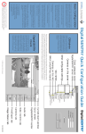
1
DS1800
Installer/User Guide
i
INSTRUCTIONS
The exclamation point within an equilateral triangle is intended to alert the
user to the presence of important operating and maintenance (servicing)
instructions in the literature accompanying the appliance.
DANGEROUS VOLTAGE
The lightning flash with arrowhead symbol, within an equilateral triangle, is
intended to alert the user to the presence of uninsulated “dangerous voltage”
within the product’s enclosure that may be of sufficient magnitude to constitute
a risk of electric shock to persons.
POWER ON
This symbol indicates the principle on/off switch is in the on position.
POWER OFF
This symbol indicates the principle on/off switch is in the off position.
PROTECTIVE GROUNDING TERMINAL
A terminal which must be connected to earth ground prior to making any other
connections to the equipment.
DS1800
Installer/User Guide
Avocent, the Avocent logo and “The Power of Being There”
are trademarks of Avocent Corporation. AutoView is a trademark of Cybex Computer Products Corporation. All other
marks are trademarks or registered trademarks of their
respective owners.
© 2001 Avocent Corporation. All rights reserved.
USA Notification
Warning: Changes or modifications to this unit not expressly approved by the party responsible for compliance could void the user's authority to operate the equipment.
Note: This equipment has been tested and found to comply with the limits for a Class A digital
device, pursuant to Part 15 of the FCC Rules. These limits are designed to provide reasonable
protection against harmful interference when the equipment is operated in a commercial
environment. This equipment generates, uses and can radiate radio frequency energy and,
if not installed and used in accordance with the instruction manual, may cause harmful
interference to radio communications. Operation of this equipment in a residential area is
likely to cause harmful interference in which case the user will be required to correct the
interference at his own expense.
Canadian Notification
This digital apparatus does not exceed the Class A limits for radio noise emissions from
digital apparatus set out in the Radio Interference Regulations of the Canadian Department
of Communications.
Le présent appareil numérique n’émet pas de bruits radioélectriques dépassant les limites
applicables aux appareils numériques de la classe A prescrites dans le Règlement sur le
brouillage radioélectrique édicté par le Ministère des Communications du Canada.
Japanese Notification
Agency Approvals
UL 1950, CSA C22. 2 No. 950, EN60950, IEC 950
FCC part 15A, EN55022, EN55024, EN61000-3-2, EN61000-3-3
Republic of Korea EMI Standard Certificate Number: E-F900-01-2012 (A)
DS1800
Installer/User Guide
Contents
Chapter 1 - Introduction/Product Overview
DS1800 Overview/Features . . . . . . . . . . . . . . . . . . . . . 1
Safety Precautions . . . . . . . . . . . . . . . . . . . . . . . . . . . . . 2
Chapter 2 - Installing the DS1800
Getting Started. . . . . . . . . . . . . . . . . . . . . . . . . . . . . . . . .
Verification of Connections. . . . . . . . . . . . . . . . . . . . . .
Setting up your Network . . . . . . . . . . . . . . . . . . . . . . . .
Installing the DS1800 Unit . . . . . . . . . . . . . . . . . . . . . .
7
8
8
8
Chapter 3 - Operations
Power Up and LEDs. . . . . . . . . . . . . . . . . . . . . . . . . . . 15
Terminal Operations . . . . . . . . . . . . . . . . . . . . . . . . . . 16
Terminal Applications Commands . . . . . . . . . . . . . . 16
Appendices
A: Flash Upgrades . . . . . . . . . . . . . . . . . . . . . . . . . . . .
B: Technical Specifications . . . . . . . . . . . . . . . . . . . . .
C: Technical Support . . . . . . . . . . . . . . . . . . . . . . . . . .
D: TCP Ports . . . . . . . . . . . . . . . . . . . . . . . . . . . . . . . . .
21
22
24
25
1
Product Overview
Contents
DS1800 Overview - Features . . . . . . . . . . . . . . . . . . . 1
Safety Precautions . . . . . . . . . . . . . . . . . . . . . . . . . . . 2
Chapter 1: Product Overview
1
Chapter 1: Introduction/Product Overview
DS1800 Overview/Features
Overview
The DS1800 digital solution provides secure, non-blocked KVM connections
to virtually any number of servers using a standard LAN connection. Operators can connect to servers no matter where they are located with performance that meets the requirements of both local and remote operators.
Because the DS1800 leverages industry standard LAN equipment, complex
wired configurations are no longer necessary. All of the analog KVM signals
are converted in real time to digital form and transported using standard
Ethernet protocols. This design allows for your future growth needs without
complex re-configuration.
Connect servers to the DS1800 or to an attached switch
Computers can be connected directly to the DS1800 or to attached AutoView
200/400 and OutLook KVM switches for a single additional tier of attached
servers. The total number of concurrent users in the system is limited only by
the number of available network ports.
Access the DS1800 via network connection
No special software or drivers are required on the attached, or Host, computers.
Users access the DS1800 and all attached systems via Ethernet from a PC
running the DSView software program. This software resides on the user PC.
User PCs can be located anywhere a valid network connection exists. The
DS1800 can be configured on a separate network “out of band” of your data
network, allowing access to your servers even if your applications network
is down.
2
DS1800 Installer/User Guide
Safety Precautions
To avoid potential video and/or keyboard problems when using Avocent products:
•
If the building has 3-phase AC power, ensure that the computer and
monitor are on the same phase. For best results, they should be on the
same circuit.
•
Use only Avocent-supplied cable to connect computers and KVM
switches. Avocent warranties do not apply to damage resulting from usersupplied cable.
To avoid potentially fatal shock hazard and possible damage to equipment,
please observe the following precautions:
•
Do not use a 2-wire extension cord in any Avocent product configuration.
•
Test AC outlets at computer and monitor for proper polarity and grounding.
•
Use only with grounded outlets at both the computer and monitor. When
using a backup power supply (UPS), power the computer, the monitor and
the DS1800 unit off the supply.
Note: The AC inlet is the main disconnect.
DC installation safety considerations
As a safety precaution, install this product in an area with limited or
controlled access. A readily accessible disconnect device that is suitably
approved and rated shall be incorporated in the field wiring. Connect field
wiring from the 48-VDC power source to the screw terminals marked “+” and
“-” on the rear panel of the unit. Connect field wiring from earth ground to
the screw terminal marked with the ground symbol. Terminals will accommodate wiring from 26 to 12 AWG (up to 2.5-mm2 maximum cross section).
Strip each wire, insert it in the square opening in the terminal block and
tighten the screw above it to a maximum of 70 ounce-inches (0.5 Nm) using
either a flat or Phillips-head driver.
Chapter 1: Product Overview
3
Rack mount safety considerations
•
Elevated Ambient Temperature: If installed in a closed rack assembly, the
operation temperature of the rack environment may be greater than room
ambient. Use care not to exceed the rated maximum ambient temperature
of the unit.
•
Reduced Air Flow: Installation of the equipment in a rack should be such
that the amount of air flow required for safe operation of the equipment
is not compromised.
•
Mechanical Loading: Mounting of the equipment in the rack should be
such that a hazardous condition is not achieved due to uneven mechanical loading.
•
Circuit Overloading: Consideration should be given to the connection of the
equipment to the supply circuit and the effect that overloading of circuits
might have on overcurrent protection and supply wiring. Consider equipment nameplate ratings for maximum current.
•
Reliable Earthing: Reliable earthing of rack mounted equipment should be
maintained. Pay particular attention to supply connections other than direct
connections to the branch circuit (for example. use of power strips).
2
Installing the DS1800
Contents
Getting Started . . . . . . . . . . . . . . . . . . . . . . . . . . . . . . 7
Verification of Connections . . . . . . . . . . . . . . . . . . . . 8
Setting Up your Network . . . . . . . . . . . . . . . . . . . . . . 8
Installing the DS1800 Unit . . . . . . . . . . . . . . . . . . . . 8
Chapter 2: Installing the DS1800
7
Chapter 2: Installing the DS1800
The DS1800 system requires that the DSView, DSAdmin and
DSAuthentication Service software be installed prior to use. DSView is the
application which allows a user to view and control a server attached to
the DS1800 system. DSAdmin is used to configure and maintain the system.
DSAuthentication is a Windows NT or 2000 service used to prevent unauthorized access to the DS1800 system. For more information on these programs,
see your DSView Installer/User Guide.
The DS1800 system uses Ethernet networking infrastructure and TCP/IP protocol to transmit keyboard, video and mouse information between operators
and connected computers. Although 10BaseT Ethernet may be used, Avocent
recommends a dedicated, switched 100BaseT network.
Getting Started
Before installing the DS1800 system, refer to the list below to ensure that
you have all items that shipped with the DS1800 as well as all other items
necessary for proper installation.
Supplied with the DS1800
Your DS1800 ships with the following items:
•
The DS1800 unit
•
A local country power cord (not included in DC version)
•
Rack mounting brackets
•
Null modem cable
•
DS1800 and DSView User Documentation and Software CD
•
DS1800 Quick Install
Needed for installation
•
Computer interface cables for each computer you plan to attach to the
DS1800 system. These cables will be single-sheath and are available with
PS/2, USB and Sun interfaces. These cables vary in length and are purchased separately from Avocent.
•
DSAuthentication, DSAdmin and DSView software. All are available on the
included CD and through download from Avocent.
8
DS1800 Installer/User Guide
Verification of Ethernet/Computer Connections
The front panel of the DS1800 features two LEDs describing the Ethernet
connection. The top LED is the Link indicator. It will illuminate when a valid
connection to the network is established and blink when there is activity on
the port. The lower amber LED, labeled 100Mbps, will indicate that you are
communicating at the 100BaseTspeed.
Additionally, there are two LEDs above each port number on the front of your
unit: one green and one amber. The green LED will illuminate when the
attached system or switch is powered. The amber LED will illuminate when
that computer or a computer attached to that switch is being accessed by the
DSView client.
Setting up Your Network
The DS1800 system uses IP addresses to uniquely identify the DSAuthentication
Service, the DS1800 units and the computers running DSView. The DS1800
supports both BootP and static IP addressing. Avocent recommends that IP
addresses be reserved for each unit and that they remain static while the
DS1800 units are connected to the network. For additional information on how
the DS1800 uses the TCP protocol, see Appendix D.
Installing the DS1800 Unit
1. Remove the DS1800 unit from the packing material.
2. Connect a terminal or PC running terminal emulation software (such as
Hyperterminal) to the terminal port on the front panel of the DS1800 using
the supplied null-modem cable. The terminal should be set to 9600 baud, 8
bits, 1 stop bit, no parity, no flow control.
3. Plug the supplied power cord into the back of the DS1800 unit and then into
an appropriate power source.
4. When the power is switched on, the Power indicator on the front of the
unit will blink for approximately 30 seconds while performing a self-test.
Approximately 10 seconds after it stops blinking, press the Enter key to
access the main menu.
Chapter 2: Installing the DS1800
9
Terminal applications
1. You will see the Terminal Applications menu with seven options.
Select Option 1, Network Configuration. This will activate the Network
Configuration menu.
2. Select Option 1 to set your network
speed. When possible, you should
set your connection manually without
relying on the auto negotiate feature.
Once you enter your selection, you will be returned to the Network Configuration menu.
3. Select Option 2 and specify if you are using a static or BootP IP address.
Avocent recommends using a static IP address for ease of configuration.
If you are using a BootP address, please configure your BootP server to
provide an IP address to the DS1800 and proceed to step 5.
4. Select options 3-5 in turn to finish configuring your DS1800 for IP Address,
Netmask and Default Gateway. Once this is completed, enter 0 in the
Network Configuration menu to return to the main menu.
5. Before a PC running Windows NT or 2000 can be connected to the DS1800,
an adjustment to mouse acceleration must be made. Follow the steps below.
NOTE: It is highly recommended that all Windows systems attached to the DS1800 use the
default Windows PS/2 mouse driver.
For Windows NT (using default drivers):
a. From the desktop, go to Start - Settings - Control Panel - Mouse.
b. Click on the Motion tab.
c. Set the pointer speed to slow. This will also need to be done for any NT
user account that will be accessing the NT system through the DS1800.
For Windows 2000:
a. From the desktop, go to Start - Settings - Control Panel - Mouse.
b. Click on the Motion tab.
c. Set the acceleration setting to none, and the speed setting to the default
of 50%.
10
DS1800 Installer/User Guide
For Sun:
a. From the common desktop environment, go to Desktop Controls - Mouse
Style Manager.
b. Set the mouse acceleration to 1.0.
6. Begin connecting servers directly to the DS1800 and/or connected KVM
switches. You can have any mix of computers and switches connected to
one DS1800 unit.
NOTE : The DS1800 supports specific AutoView and OutLook switches. Contact Avocent
technical support or your reseller for details.
To connect a user interface cable to a server:
Locate the user interface cables that you purchased with your DS1800 unit.
Ensure that the cable is compatible with the computer you
are connecting. Connect this
cable to the keyboard, monitor and mouse ports on the
first computer you will be
attaching to this DS1800 unit.
Repeat this step for all computers you wish to attach.
To connect a user interface
cable to a KVM switch:
Plug the keyboard, video and mouse connectors on your computer interface
cable into the user keyboard, monitor and mouse ports on the rear panel
of your switch. Repeat this step for each
KVM switch in your system.
7. Attach the DB25 connector on the
remaining end of the computer interface
cable to the DS1800 rear panel in an
available computer port. Repeat this
step for each computer interface cable
in the system.
NOTE: The DS1800 and all attached computers should be powered down before servicing the
unit. Always disconnect the power cord from the wall outlet.
Chapter 2: Installing the DS1800
11
8. Connect your network cable from the LAN port on the rear of the DS1800
to your network.
9. Power the DS1800 via the power switch on the rear of the unit, then power
all attached systems.
NOTE: Your software registration key will be necessary for all installations. Internet Explorer 5.0 or
higher must be installed on all systems running DS1800 software.
Once you have completed installation of your DS1800 hardware, you will need
to install the software that will allow you to access attached computers. You
can find software installation instructions in your DSView Installer/User Guide.
3
Operations
Contents
Power up and LEDs . . . . . . . . . . . . . . . . . . . . . . . . 15
Terminal Operations . . . . . . . . . . . . . . . . . . . . . . . . 16
Terminal Applications Commands . . . . . . . . . . . . 16
Chapter 3: Operations
15
Chapter 3: Operations
Throughout this chapter and the rest of the manual, the following naming
conventions will be used:
Host PC
- A computer that is attached to the DS1800 and controlled
through the DSView software
Node
- A Host PC
Port
- One of the eight PC/KVM Switch interfaces on the DS1800
Remote PC - The computer running DSView
Session
- The process of accessing and controlling a single Host PC connected to a DS1800 unit from a PC running DSView. More than
one session at a time may be launched and active using DSView.
Power Up and LEDs
The DS1800 should be powered up before any attached servers or switches.
Indicator lights on the front of the unit will illuminate to indicate the status
and activity of each port and a green LED labeled Power will show that the
unit is receiving power.
There are two LEDs above each port number on the front of your unit: one
green and one amber. The green LED will illuminate when the attached
system or switch is powered. The amber LED will illuminate when that
computer or a computer attached to that switch is being accessed by a
DSView client.
There are also LEDs on the DS1800 front panel to indicate the status of your
LAN connection. If you are successfully linked to the network, the green LED
labeled Link will be lit and an amber LED labeled 10/100 will indicate that you
are communicating at the proper speed. This LED will blink if there is activity
on the associated DS1800 unit.
Finally, you will find a 9-pin serial connector labeled Terminal on the right end
of the front panel of the DS1800. This is used to configure the DS1800 and will
be discussed further in Chapter 4.
Once the DS1800 is configured and powered, users may connect to attached
systems through the DSView software. For more information on DSView, see
the DSView Installer/User Guide.
16
DS1800 Installer/User Guide
Terminal Operations
Each individual DS1800 may be configured at the unit level through the
Terminal port on the front of the unit. All terminal commands are accessed
through a terminal or PC running terminal emulation software.
Accessing the Terminal Menu
1. Connect a terminal or PC running terminal emulation software (such as
Hyperterminal) to the Terminal port on the front panel of the DS1800 using
the supplied null-modem cable. The terminal should be set to 9600 baud, 8
bits, 1 stop bit, no parity and no flow control. The terminal may be connected
at any time, even when the unit is powered.
2. Press any key to access the main menu.
Terminal Applications Menu Commands
The Terminal Applications menu of the DS1800 features seven selections:
Network Configuration, Security Configuration, Firmware Management,
Enable Debug Messages, Set/Change Password, Configure Sun Keyboard
Layout Code and Exit. Each are discussed below.
Network configuration
The DS1800 is configured for network access through this option. When it is
selected, you will have access to the addressing that allows the DS1800 to be
positioned in your network.
Security configuration
This menu option allows you to configure DS1800 authentication security. When
it is selected, you will be given two menu options: Reset Authentication Tokens
and Authentication Server Connection Status.
The DS1800 operates in one of two modes: All or Secure. This setting is
controlled from the Security menu on the DS1800 console port. In the default
All mode, the DS1800 allows any authentication server to initiate a session
between the DS1800 and DSView. In Secure mode, only one specific authentication server is allowed to initiate this session; other authentication servers
are locked out.
NOTE: In secure mode the ability to select a backup authentication server through DSView
is eliminated.
Chapter 3: Operations
17
When a DS1800 is added to the database with DSAdmin, the appropriate
Authentication Token is added to the DS1800 automatically. If
DSAuthentication cannot contact the DS1800 to add the token, an error message is displayed and the DS1800 is not added to the database.
When the last reference to a DS1800 is removed from the database, the Authentication Token is removed from the DS1800, which allows the DS1800 to be
moved from one authentication server to another. The Authentication Token
can also be removed from the Security menu on the DS1800 console port via
the Reset Authentication Tokens option.
When the DS1800 is in All mode, DSAdmin displays a warning message
when the DS1800 is added to the database, stating that the token could not
be installed. If you intend to operate in All mode you may safely ignore this
warning. Otherwise, you may wish to change the security settings on the
console port of the DS1800.
Firmware management menu
This menu option allows you to access two commands: Flash Download and
Toggle Boot Firmware. The Flash Download selection allows you to upgrade
your DS1800 firmware with upgrades available from Avocent. You may use the
Toggle Boot Firmware command to switch from your current firmware back to
the original factory firmware installed on your DS1800 unit. For more information on Flash upgrading your DS1800 see Appendix C: Flash Upgrading.
Enable debug messages menu
This menu option allows you to configure the DS1800 to display messages
regarding the status of the DS1800 unit. Once you select the level of detail you
wish to receive, the DS1800 will begin to display information on your terminal
screen. When you are finished viewing, press any key to exit this mode.
Set/change password
The DS1800 can be set to a secure mode where the Terminal menu cannot be
accessed without first entering a password.
To activate security:
1. Select the Set/Change Password menu option. You will be prompted to
decide if you wish to continue. Enter a Y.
2. Enter a password for this DS1800 unit and press Enter. This password may
be up to 14 characters long.
18
DS1800 Installer/User Guide
3. You will be prompted to re-enter the password. Once you complete this
step, security will be active and you will not be able to access DS1800
Terminal Operations without the password.
To change the password:
Select the Set/Change Password menu option. You will be prompted to enter
the old password and a new one. Re-enter the new password to verify.
CAUTION : This password places your DS1800 terminal in a secure mode. This password
should be guarded like any network password and care should be taken to avoid forgetting or
misplacing it. There are no means for recovering a lost password.
Configure Sun keyboard layout code
The DS1800 provides support for Sun keyboard layouts for various countries.
Selecting this menu item will allow you to configure each Sun computer
individually. To do this:
1. Select the Configure Sun Keyboard Layout Code option. You will be
prompted for which channel to modify. Select the channel that your Sun
computer is attached to and press Enter.
2. A list of supported country code layouts will appear. Select the appropriate
layout and press Enter. Repeat this process for every Sun computer in your
DS1800 system.
Exit
This menu selection will return you to the ready prompt.
Appendices
Contents
A: FLASH Upgrades . . . . . . . . . . . . . . . . . . . . . . . . 21
B: Technical Specifications . . . . . . . . . . . . . . . . . . . 22
C: Technical Support . . . . . . . . . . . . . . . . . . . . . . . . 24
D: TCP Ports . . . . . . . . . . . . . . . . . . . . . . . . . . . . . . 25
Chapter 4: Appendices
21
Appendix A: FLASH Upgrades
The DS1800 FLASH upgrade feature allows you to update your unit with
the latest firmware available. To perform this update, you will first need a
Trivial FTP (TFTP) server. If you do not have a TFTP server, there are several
shareware programs that you can download.
You can find a freeware TFTP server at http://klever.net/kin/canned/PumpKIN.exe
Next you will need to download the latest FLASH firmware from Avocent at
http://register.avocent.com. Save the FLASH upgrade file to the appropriate
directory on the TFTP server.
Once this is complete, the following steps will upload the new FLASH file:
1. Connect a terminal or PC running terminal emulation software (such as
Hyperterminal) to the Terminal port on the front panel of the DS1800 using
the supplied null-modem cable. The terminal should be set to 9600 baud, 8
bits, 1 stop bit, no parity, no flow control.
2. If the DS1800 is not on, turn it on now. After approximately 10 seconds,
press any key to access the main menu.
3. You will see the Terminal Applications menu with six options. Select
Option 2, Firmware Management. (Please note: the current version of your
firmware will be displayed on the Firmware Management screen.)
4. Select Option 1, FLASH Download.
5. Enter the IP Address of your TFTP server and press Enter.
6. Enter the name of the file that you downloaded from the Avocent site.
7. Confirm the TFTP download by entering a Y or yes and pressing Enter.
8. The DS1800 will verify that the file you downloaded is valid. Next, you will
be prompted to confirm the upgrade. Enter a Y or yes and press Enter
to confirm.
9. The DS1800 will begin the FLASH upgrade process. On-screen indicators
will display the upgrade progress. When the upload is complete, the DS1800
will reset and upgrade the internal subsystems.
WARNING: Do not cycle power to the DS1800 during this process. A loss of power will render the
DS1800 inoperable and require the unit be returned to the factory for repair.
10. Once the upgrade is complete, a verification message will appear on screen.
22
DS1800 Installer/User Guide
Appendix B: Technical Specifications
Product Specifications
Dimensions
Height
1.75
4.45
Width
17.00
43.18
Depth
11.00 in
27.94c
Weight
8lbs (3.6kg) without cables
Input Power Requirements
Power Consumption
27 watts
AC-input power
40W maximum
Maximum AC-input (AC Version)
100 to 240 VAC wide input
Maximum DC-input (DC Version)
36 to 75 VDC wide input
AC-input current rating
2A
AC-input cable
18 AWG three-wire cable, with a three lead IEC-320 receptacle on the
power supply end and a country dependant plug on the power resource
end
Frequency
50/60 Hz Auto Sensing
Temperature
Operating Temp
32 to 104 degrees Fahrenheit (0 to 40 degrees Celsius) operating;
-4 to 149 degrees Fahrenheit (-20 to 65 degrees Celsius) nonoperating
Heat Dissipation
92 Btu/hr
Airflow
8 cfm
Humidity
10 to 90% noncondensing
Server Ports
Number
8
Types
PS/2 Keyboard, PS/2 Mouse, SXGA Video
USB Keyboard, USB Mouse, SXGA Video
Sun Keyboard, Sun Mouse, SXGA Video
Sun Keyboard, Sun Mouse, 13W3 Video
Sun USB Keyboard, USB Mouse, 13W3 Video
Connectors
25-pin D with locking thumb screws
Chapter 4: Appendices
23
Sync Types
Separate horizontal and vertical composite
Plug and Play
DDC2B
Video Resolution
Maximum 1280 x 1024 @ 75Hz
Agency Approvals
UL 1950, CSA C22.2, EN60950, FCC part 15A, EN55022, EN55024,
EN61000-3-2, EN61000-3-3, Republic of Korea EMI Standard
Certificate Number: E-F900-01-2012 (A)
Console Port
Number
1
Type
Serial RS232
Connectors
DB9 Male Network Connection
Number
1
Type
Ethernet: IEEE 8023, 10 Base-T, Fast Ethernet: IEEE 802.3U,
100BaseT
Connector
RJ45
User Consoles
Type
PC running Windows NT, 2000, 95/98, Operating Systems
with the DSView application
Minimum Configuration- 300MHz Pentium III with 64Mb RAM,
100BaseT NIC, XGA Video
Recommended Configuration- 450MHz Pentium III with 128Mb Ram,
100BaseT NIC, SXGA Video
24
DS1800 Installer/User Guide
Appendix C: Technical Support
Our Technical Support staff is ready to assist you with any installation or
operating issues you encounter with your Avocent product. If an issue should
develop, follow the steps below for the fastest possible service:
1. Check the pertinent section of the manual to see if the issue can be resolved
by following the procedures outlined.
2. Check our web site at www.avocent.com/support and look at the searchable
knowledge base or use the on-line service request.
3. Call Avocent Technical Support for assistance. To expedite assistance, have
this manual available, along with a copy of your invoice giving the date
of purchase. DS1800 Technical Support is available 24 hours a day, seven
days a week at (256) 430-4000. You may also call toll free at (888) 793-8763.
Chapter 4: Appendices
25
Appendix D: TCP Ports
When the DSView client is started, the Node Manager will become active.
Node Manager will try to establish a SSPI Messenger Class session
using TCP/IP over port 2068 to the DSAuthentication Server (Avocent
Service). First, Node Manager will use the current NT/2000 cached credentials to establish the session.
If the cached credentials have
DSAuth Server
the proper permissions, the
browse list is returned from
the DSAuthentication Server
Avocent
Avocent
Authentication
Service
over TCP/IP port 2068. Note
Service
TCP/IP
Port
8191
that the DSView client caches
this list. Using the refresh
DS1800
TCP/IP
option will update the list
Port 2068
TCP/IP
from the DSAuthentication
Port 8192
Server. If the session is
refused using the cached creDSView
DSAdmin
Client
Client
dentials, a popup dialog box
will prompt for the proper
username and password.
Remote User
After the browse list is returned to Node Manager, the user can double-click
on a specific port to initiate a KVM session with that port on the DS1800.
The DSView client contacts the DSAuthentication Server, which checks the
permissions on the port again. If the user has permissions to the port selected,
the DSAuthentication Server will establish a connection to the DS1800 using
TCP/IP port 8191. The DSAuthentication Server then tells the DS1800 to listen
to port 8192 for a DSView connection.
For debugging purposes, the
details of this connection can
been seen by using the console
port to place the DS1800 into
debug mode.
DSAuth Server
TCP/IP
Avocent
Authentication
Service
Avocent
Service
Port 8191
DS1800
TCP/IP
TCP/IP
Port 2068
Port 8192
DSView
Client
Remote User
DSAdmin
Client
26
DS1800 Installer/User Guide
The DSView client establishes a TCP/IP session with the DS1800 over
the TCP/IP port 8192. The DS1800 verifies with the DSAuthentication
Server that the calling DSView client
DSAuth Server
has permission to have a KVM session
with the selected port. Then the conAvocent
nection between the DS1800 and the
Avocent
Authentication
Service
Service
TCP/IP
DSAuthentication Server is closed. All
Port 8191
communication between the DS1800
DS1800
TCP/IP
Port 2068
and the DSView client takes place over
TCP/IP
Port 8192
TCP/IP port 8192 until the DSView
DSView
DSAdmin
client closes the session.
Client
Client
Remote User
If the DSView user wishes to establish a session with another DS1800 port, the
same process is used.
DSAuth Server
TCP/IP
Avocent
Authentication
Service
Avocent
Service
Port 8191
DS1800
TCP/IP
Port 2068
TCP/IP
TCP/IP
Port 2068
TCP/IP
Port 8190
Port 8192
TCP/IP
DS1800
Port 8192
DSView
Client
Remote User
DSAdmin
Client
Chapter 4: Appendices
DSAdmin functions similarly to the DSView
client. It establishes a connection using
TCP/IP port 2068, and uses the same process
for authentication and return of the browse
list. Changes made to the browse list
through DSAdmin are transmitted back to the
DSAuthentication Server using TCP/IP port
8190. After the changes are made, DSAdmin
refreshes its browse list view over the TCP/IP
port 2068 connection.
DSAuth Server
Avocent
Authentication
Service
TCP/IP
Port 2068
When the backup Authentication Service is
active, it communicates with the primary
Avocent Authentication Service via TCP port
8193. Changes to the topology are copied to
and from the primary over this port.
DSView
Client
Remote User
Full Diagram
DSAuth Server
TCP/IP
Avocent
Authentication
Service
Avocent
Service
Port 8191
DS1800
TCP/IP
Port 2068
TCP/IP
Port 8192
TCP/IP
DS1800
Port 8192
DSView
Client
Remote User
27
DSAdmin
Client
Avocent
Service
TCP/IP
Port 8190
DSAdmin
Client
LIMITED WARRANTY
Avocent Corporation warrants to the original retail purchaser that this product is and will be free from defects in
materials and workmanship for a period of 12 months from the date of purchase.
Additionally, all Avocent products carry an unconditional thirty-day satisfaction guarantee. If, for any reason,
you are dissatisfied with the performance of this product, you may return it to the point of purchase for a refund
of the purchase price (excluding shipping charges). This guarantee does not apply to special order products, and
may not be available through all resellers. During the warranty period, purchaser must promptly call Avocent
for a RETURN MATERIALS AUTHORIZATION (RMA) number. Make sure that the RMA number appears on
the packing slip, proof of purchase, AND ON THE OUTSIDE OF EACH SHIPPING CARTON. Unauthorized
returns or collect shipments will be refused.
Ship prepaid to:
Avocent Corporation
4991 Corporate Drive
Huntsville, AL 35805 U.S.A.
Telephone: (256) 430-4000
The above limited warranty is voided by occurrence of any of the following events, upon which the product is
provided as is, with all faults, and with all disclaimers of warranty identified below:
1.
2.
3.
4.
5.
6.
7.
8.
If non-Avocent approved cabling is attached to the product. Poorly constructed and miswired cabling
can diminish video quality and damage equipment. Avocent manufactured cabling is built to high
quality standards utilizing overall braided shield to comply with FCC emission standards, and each
cable is individually tested under load.
If defect or malfunction was caused by abuse, mishandling, unauthorized repair, or use other
than intended.
If unauthorized modifications were made to product.
If unreported damages occurred in any shipment of the product.
If damages were due to or caused by equipment or software not provided by Avocent.
If the product is used with non-grounded or incorrectly polarized AC power.
If the product is used in contradiction to any instruction provided by any User Guide or Instruction
Sheet provided to you or with the product.
If the product is damaged due to power surges, water exposure or act of God including lightning.
EXCEPT AS SPECIFICALLY PROVIDED ABOVE AND TO THE MAXIMUM EXTENT ALLOWED BY LAW,
AVOCENT CORPORATION DISCLAIMS ALL WARRANTIES AND CONDITIONS WHETHER EXPRESS,
IMPLIED, OR STATUTORY AS TO ANY MATTER WHATSOEVER INCLUDING, WITHOUT LIMITATION,
TITLE, NON-INFRINGEMENT, CONDITION, MERCHANTABILITY OR FITNESS FOR ANY PARTICULAR
OR INTENDED PURPOSE.
EXCEPT AS EXPRESSLY PROVIDED ABOVE AND TO THE MAXIMUM EXTENT ALLOWED BY LAW,
AVOCENT CORPORATION SHALL NOT BE LIABLE FOR ANY SPECIAL, INDIRECT OR CONSEQUENTIAL
DAMAGES (INCLUDING WITHOUT LIMITATION, LOSS OF PROFIT, LOSS OF BUSINESS, LOSS OF
INFORMATION, FINANCIAL LOSS, PERSONAL INJURY, LOSS OF PRIVACY OR NEGLIGENCE) WHICH MAY
BE CAUSED BY OR RELATED TO, DIRECTLY OR INDIRECTLY, THE USE OF A PRODUCT OR SERVICE,
THE INABILITY TO USE A PRODUCT OR SERVICE, INADEQUACY OF A PRODUCT OR SERVICE FOR
ANY PURPOSE OR USE THEREOF OR BY ANY DEFECT OR DEFICIENCY THEREIN EVEN IF AVOCENT
CORPORATION OR AN AUTHORIZED AVOCENT DEALER HAS BEEN ADVISED OF THE POSSIBILITY
OF SUCH DAMAGES OR LOSSES.
©2001 Avocent Corporation. All rights reserved.
For Technical Support:
Email: [email protected]
www.avocent.com
Avocent Corporation
4991 Corporate Drive
Huntsville, Alabama 35805-6201 USA
Tel: +1 256 430 4000
Fax: +1 256 430 4031
Avocent International Ltd.
Avocent House, Shannon Free Zone
Shannon, County Clare, Ireland
Tel: +353 61 715 292
Fax: +353 61 471 871
Avocent Asia Pacific
Singapore Branch Office
100 Tras Street, #15-01/2
Amara Corporate Tower
Singapore 079027
Tel: +65 227 3773
Fax: +65 223 9155
Avocent Germany
Gottlieb-Daimler - Straße 2-4
D-33803 Steinhagen
Germany
Tel: +49 5204 9134 0
Fax: +49 5204 9134 99
Avocent Canada
50 Mural Street, Unit 5
Richmond Hill, Ontario
L4B 1E4 Canada
Tel: +1 877 992 9239
Fax: +1 877 524 2985
590-220-001 Rev B