1
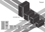
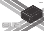
EAGE1040TG-PM
EAGE540TG-PM
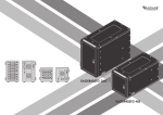
EAGE8402TG-ES
EAGE4402TG-ES
■ Content
page
1
2
2.5” HDD
EAGE8402TG-ES & EAGE4402TG-ES
A. Product Overview -Front
B. Product Overview -Rear
3
C. Switching Power Supply Voltage
D. Install 2.5” Hard Drive
E. Power ON/OFF System
F. Locking and Unlocking Door
4
G. Connect to Your Computer
5
H. iStarUSAcare
6
7
3.5” HDD
EAGE1040TG-PM & EAGE540TG-PM
A. Product Overview -Front
B. Product Overview -Rear
8
C. Switching Power Supply Voltage
EAGE8402TG-ES
D. Install 3.5” Hard Drive
EAGE4402TG-ES
E. Power ON/OFF System
F. Locking and Unlocking Door
9
G. Connect to Your Computer
H. iStarUSAcare
User’s Manual
1
eSATA Series|EAGE8402TG-ES|EAGE4402TG-ES
A
B
Product Overview - Front
1
2
Product Overview - Rear
4
7
5
1
3
2
8
7
6
8
7
8
3
6
4
EAGE8402TG-ES
EAGE8402TG-ES
EAGE4402TG-ES
5
EAGE4402TG-ES
1
POWER LED
4
POWER SWITCH
2
HDD ON/OFF SWITCH & LED
5
AC INLET
3
KEY LOCK
6
110V/220V SWTICH
7
eSATA CONNECTOR x4
8
60mm FAN
LED Behavior
POWER LED
Color
Status
Solid Green
System Power ON
Off
System Power OFF
HDD LED
Color
Status
Solid Blue
HDD Power ON
Blinking Blue
Drives Working (Read/Write)
Off
HDD Power OFF
*please note: some of SSDs (Solid-State Drive) do not support access (read/write) signal.
User’s Manual
2
eSATA Series|EAGE8402TG-ES|EAGE4402TG-ES
C
E
Switching Power Supply Voltage
Powering ON/OFF System
*CAUTION:
Ensure the power supply voltage selector switch is correctly set for
your region before use
Wrong voltage setting will cause damages on devices
1
1. Make sure power switch in the back of chassis is in ON position
2
115
3
230
1. Switch to right voltage setting before turning on power switch
D
2. Tighten two hand screws to secure HDD tray
3. Push individual power buttons to power on each hard drive
4. Push power buttons again to power off hard drives
*CAUTION:
To prevent drive failures or data loss,
unmount the device in OS before powering off hard disk bay
Installing 2.5” Hard Drive
F
1
Locking and Unlocking Door
1. Turn the key clockwise to lock the door
2. Turn the key counterclockwise to unlock the door
2
3
1. Pull HDD tray out
2. Install 2.5 HDD onto tray
3. use four M3 screws to secure 2.5” HDD to tray
User’s Manual
3
eSATA Series|EAGE8402TG-ES|EAGE4402TG-ES
G
G
Connect to Your Computer by eSATA
Connect to Your Computer by miniSAS
eSATA Cable
4 eSATA to SFF-8088 cable
eSATA Cable
EAGE8402TG-ES
EAGE8402TG-ES
Eight eSATA cables are required.
Two SFF-8088 to 4 eSATA cables are required.
one for disk 1~4, second for disk 5~8.
eSATA Cable
4 eSATA to SFF-8088 cable
eSATA Cable
EAGE4402TG-ES
EAGE4402TG-ES
Four eSATA cables are required.
One SFF-8088 to 4 eSATA cable is required.
Raid Control Card
Raid Control Card
EAGE8402TG-ES requires controllers with a total of eight
eSATA connectors.
EAGE4402TG-ES requires a controller with four eSATA
connectors.
EAGE8402TG-ES requires a controller with two SFF-8088
connectors.
EAGE4402TG-ES requires a controller with one SFF-8088
connector.
*please make sure all the cable connectors are secured (locked) properly.
*please make sure all the cable connectors are secured (locked) properly.
User’s Manual
4
eSATA Series|EAGE8402TG-ES|EAGE4402TG-ES
H
iStarUSAcare
We will help you navigate our website to find the information that you
need. Go to www.istarusa.com , and click on live chat bubble above the
Search Bar.
Our technicians are standing by to take your questions.
Visit http://istarusa.com/support/ , and you will receive a technical
support ticket to help track your requests from the beginning to the end.
Or you can contact us @888-989-1189
Copyright:
Copyright © 2014 by iStarUSA Global, all rights reserved. No part of this publication may be reproduced, transmitted, transcribed, stored in a retrieval system, translated into any language, in any
form or by an means or otherwise, without the prior written permission of iStarUSA Global. 727
Phillips Dr., City of Industry, CA 91748.
iStarUSA Global reserves the right to make modification and additions to this product and manual
without notice or taking any liability.
Disclaimer:
iStarUSA Global assumes no liability for errors or omissions in this document. Nor does iStarUSA
Global make any commitment to update the information contained herein. Pictures in this document are for demonstration purpose only and may not be the same as the actual product.
User’s Manual
5
eSATA Series|EAGE8402TG-ES|EAGE4402TG-ES
■ Content
page
6
7
3.5” HDD
EAGE1040TG-PM & EAGE540TG-PM
A. Product Overview -Front
B. Product Overview -Rear
8
C. Switching Power Supply Voltage
D. Install 3.5” Hard Drive
E. Power ON/OFF System
F. Locking and Unlocking Door
9
G. Connect to Your Computer
H. iStarUSAcare
EAGE1040TG-PM
User’s Manual
6
EAGE540TG-PM
eSATA Series|EAGE1040TG-PM|EAGE540TG-PM
A
B
Product Overview - Front
Product Overview - Rear
1
4
2
3
1
4
2
4
3
5
5
5
6
7
EAGE1040TG-PM
EAGE540TG-PM
1
POWER LED
2
HDD ON/OFF SWITCH & LED
3
KEY LOCK
EAGE1040TG-PM
LED Behavior
POWER LED
Status
Color
Solid Green
System Power ON
Off
System Power OFF
HDD LED
6
7
8
8
EAGE540TG-PM
4
120mm FAN
5
eSATA CONNECTOR
6
POWER SWITCH
7
AC INLET
8
110V/220V SWTICH
Status
Color
Solid Blue
HDD Power ON
Blinking Blue
Drives Working (Read/Write)
Off
HDD Power OFF
*please note: some of SSDs (Solid-State Drive) do not support access (read/write) signal.
User’s Manual
7
eSATA Series|EAGE1040TG-PM|EAGE540TG-PM
C
E
Switching Power Supply Voltage
Powering ON/OFF System
*CAUTION:
Ensure the power supply voltage selector switch is correctly set for
your region before use
Wrong voltage setting will cause damages on devices
1
1. Make sure power switch in the back of chassis is in ON position
2
3
115
230
1. Switch to right voltage setting before turning on power switch
D
2. Tighten two hand screws to secure HDD tray
3. Push individual power buttons to power on each hard drive
4. Push power buttons again to power off hard drives
Installing 3.5” Hard Drive
*CAUTION:
To prevent drive failures or data loss,
unmount the device in OS before powering off hard disk bay
F
1
Locking and Unlocking Door
1. Turn the key clockwise to lock the door
2. Turn the key counterclockwise to unlock the door
2
3
1. Pull HDD tray out
2. Install 3.5 HDD onto tray
3. use four #6-32 screws to secure 3.5” HDD to tray
User’s Manual
8
eSATA Series|EAGE1040TG-PM|EAGE540TG-PM
G
H
Connect to Your Computer
iStarUSAcare
We will help you navigate our website to find the information that you
need. Go to www.istarusa.com , and click on live chat bubble above the
Search Bar.
eSATA Cable
Our technicians are standing by to take your questions.
Visit http://istarusa.com/support/ , and you will receive a technical
support ticket to help track your requests from the beginning to the end.
Or you can contact us @888-989-1189
eSATA Cable
EAGE1040TG-PM
Two eSATA cables are required.
one for disk 1~5, second for disk 6~10.
eSATA Cable
EAGE540TG-PM
One eSATA cable is required.
Copyright:
Copyright © 2014 by iStarUSA Global, all rights reserved. No part of this publication may be reproduced, transmitted, transcribed, stored in a retrieval system, translated into any language, in any
form or by an means or otherwise, without the prior written permission of iStarUSA Global. 727
Phillips Dr., City of Industry, CA 91748.
iStarUSA Global reserves the right to make modification and additions to this product and manual
without notice or taking any liability.
Raid Control Card
EAGE1040TG-PM requires a controller that supports Port
Multiplier function with two eSATA connectors.
EAGE540TG-PM requires a controller that supports Port
Multiplier function with one eSATA connector.
Disclaimer:
iStarUSA Global assumes no liability for errors or omissions in this document. Nor does iStarUSA
Global make any commitment to update the information contained herein. Pictures in this document are for demonstration purpose only and may not be the same as the actual product.
*please make sure all the cable connectors are secured (locked) properly.
User’s Manual
9
eSATA Series|EAGE1040TG-PM|EAGE540TG-PM