1
14.4 Software
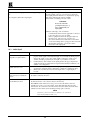
Problem
Software version is not updated
Remedy
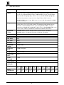
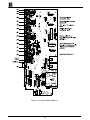
Carefully remove the switcher cover and identify the EPROM chip that is located
in the middle of the main board, marked by a white sticker. Remove the chip
with the proper tools and insert the new EPROM carefully, observing proper
polarity.
14.5 Control
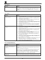
Problem
No control of switcher from VS2000 control panel
Remedy
3.
4.
5.
6.
7.
No control of switcher from PC
software
1.
2.
3.
4.
5.
6.
7.
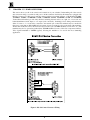
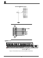
Confirm that the connecting cable is wired for pins 1-9 straight through.
Confirm that all DIP switches on the switcher have been set properly. Keep in
mind that if you are only controlling one switcher on a specific port, that
switcher must be assigned the ID of “ 1” .
If controlling more than one switcher on a single port, all switchers must be
of the same type and power to all switchers must be on.
Confirm that you have the proper machine number and control port selected
on the VS-2000. For instance, if you are controlling a single machine on port
1, then both of these should be set to “ 1” .
Confirm that you have the proper switcher type selected on the VS-2000. If
not, go back to Section 12.2.3 of this manual “ Using the VS-2000 Remote
Control Panel” .
Confirm the wiring of the connecting cable. This pin configuration may be
found in Section 11 “ Connecting to a PC or Compatible System” . Cable
length should not exceed 25 feet.
Confirm that all DIP switches on the switcher have been set properly. Keep in
mind that if you are only controlling one switcher on a specific port, that
switcher must be assigned the ID of “ 1” .
If controlling more than one switcher on a single port, all switchers must be
of the same type and power to all switchers must be on.
Confirm that the baud rate of your computer COM port is set to the same as
that of your switcher (9600-Baud). Confirm that the proper COM port is
selected in the control software.
Confirm that bi-directional communication is enabled on all switchers. Please
refer to Section 9 “ The Configuration Switches jumpers and trimmers” for
proper configuration for your switcher.
With custom software, do not send multiple commands at the same time. The
switcher must complete one command before receiving another.
Confirm that the computer you are using supports true RS-232C protocol.
Computers, such as the Apple Macintosh do not!
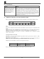
14.6 Switching Malfunctions
Problem
The switcher succeeds in switching
a number of sources then fails to
switch one
Remedy
Malfunction in the particular source or cable assembly.
NOTE: The most common failure mode in transferring the signal of an audio
source is a break in the connecting wire.
Disconnect the source from a channel that is switching successfully and connect
the suspect source to it. If the channel continues to switch successfully, then
there is something wrong with the switcher or the suspect source was not
connected properly. If it does not continue to switch successfully, then there is
something wrong with the source or cable assembly. Check them.
The switcher turns ON but will not
switch at all
KRAMER ELECTRONICS LTD.
One of the two flat cables leading from the main board to the control board may
be disconnected and the switch command is not being transferred to the switcher.
22