1
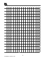
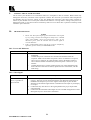
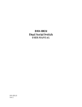
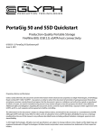
KRAMER ELECTRONICS, Ltd.
USER MANUAL
Kramer SDI Switchers and Matrices
Models:
SD-7308
SD-7388
SD-7316
IMPORTANT: Before proceeding, please read paragraph entitled
"Unpacking and Contents"
KRAMER ELECTRONICS LTD.
P/N: 2900-006001
Table Of Contents
Section
Name
1
1.1
1.2
1.3
1.4
1.5
2
3
4
4.1
5
5.1
5.2
5.3
6
6.1
7
7.1
7.2
7.3
7.4
8
8.1
8.2
9
10
10.1
10.2
INTRODUCTION
A Word on Video Switchers and Matrices
Digital and Analog Video Signals
Several Points to Consider When Working with Digital Signals
SDI Standards
Factors Affecting Quality of Results
SPECIFICATIONS
HOW DO I GET STARTED?
UNPACKING AND CONTENTS
Optional Accessories
SDI SWITCHER AND MATRICES
Getting to Know Your SD-7308
Getting to Know Your SD-7388
Getting to Know Your SD-7316
INSTALLATION
Rack Mounting
CONNECTING TO DIGITAL VIDEO DEVICES
Turning On the Machines
Operation
RS-232 Communication Protocol for SD-7308
DIP Switch Settings for the SD-7308
OPERATION OF THE SD-7388 AND SD-7316
Menu Commands for the SD-7388 and SD-7316
Communication Protocol for the SD-7388/7316
TAKING CARE OF YOUR MACHINE
TROUBLESHOOTING
Power and Indicators
Video Signal
Limited Warranty
Page
2
2
2
3
4
4
5
6
6
6
7
7
8
9
10
10
10
10
10
11
11
12
12
14
21
21
21
21
22
List Of Illustrations
Figure
1
2
3
4
5
6
Page
Digital “EYE” Diagram
The Digital “EYE” after accumulating Noise and Jitter
SD-7308 Front/Rear Panel Features
SD-7388 Front/Rear Panel Features
SD-7316 Front/Rear Panel Features
RS-232 Null Modem Connection
3
4
7
8
9
20
List Of Tables
Table
1
2
3
4
5
6
Page
SD-7308 Front/Rear Panel Features
SD-7388 Front/Rear Panel Features
SD-7316 Front/Rear Panel Features
DIPSWITCH Settings for the SD-7308
Instruction Codes for Protocol 2000
Example- HEX table for 16x16 Video Matrix Switch
1
KRAMER ELECTRONICS LTD.
7
8
9
11
15
18
1
INTRODUCTION
Congratulations on your purchase of this Kramer Electronics SDI Switcher/Matrix. Since 1981, Kramer has
been dedicated to the development and manufacture of high quality video/audio equipment. The Kramer line
has become an integral part of many of the best production and presentation facilities around the world. In
recent years, Kramer has redesigned and upgraded most of the line, making the best even better. Kramer’s line
of professional video/audio electronics is one of the most versatile and complete available, and is a true leader in
terms of quality, workmanship, price/performance ratio and innovation. In addition to the Kramer line of high
quality switchers, such as the one you have just purchased, Kramer also offers a full line of high quality
distributors, processors, interfaces, controllers and computer-related products.
This manual includes configuration, operation and option information for the following products from the
Kramer line of SDI Switchers and Matrices. All of them are similar in operation and features.
SD-7308 – 8x1 SDI Switcher
SD-7388 – 8x8 SDI Matrix
SD-7316 – 16x16 SDI Matrix
1.1
A Word on Video Switchers and Matrices
A video switcher usually switches between several sources (inputs) and one or more acceptors (outputs). A
switcher that allows several inputs to be connected to several outputs simultaneously is called a Matrix
Switcher. Switchers may be of the electronic or mechanical type. Most matrices are of the active electronic type,
with many crosspoints. Vertical interval switching, frequently used in video, ensures that the transition from one
video source to another (such as switching between two genlocked cameras) is smooth and without interference.
The switching and changeover is done during the blanked vertical interval period, when the transition is hidden
from the eyes. Vertical interval switching is needed when recording or transmitting a video program involving
several video sources, as in live broadcast, to ensure clean, undisturbed picture transitions. The switched sources
should be genlocked. Some matrices have a special, additional input – a genlock input, which is used to genlock
the matrix to an external genlock or a studio master reference. Digital (SDI) matrices usually have an analog
genlock input, while very few of them offer an additional digital genlock input. Matrices and switchers may
sometimes be RS-232 or RS-485/422 controlled. Each of these options is a way of remotely controlling a
video/audio device (switcher etc.) using a PC with a serial port, or another device that uses a similar
communication protocol. The simplest connection between the RS-232 controller and the controlled device uses
two wires (TRANSMIT, RECEIVE) and a common ground wire.
1.2
Digital and Analog video signals
An analog signal varies continuously. It may have any value (within its physical bounds) and can change at
any instant. A digital signal is made up of a finite number of discrete levels, usually – but not always –
changing only at discrete time periods. An example of a digitized waveform is shown below.
ANALOG SIGNAL
DIGITAL SIGNAL
2
KRAMER ELECTRONICS LTD.
1.3
Several Points to Consider When Working with Digital Signals
The minimum noise introduced by quantizing is 1 bit (1 level), so the higher the number of bits, the lower the
inherent noise, and the higher the resolution.
Since A/D and D/A conversions create artifacts, it is important not to convert back and forth. In a “mixed”
outfit, the video should be digitized, and all the digital processing done before converting back to analog.
“Multi-media” systems usually quantize the video to 8 bit (ie. 28 = 256) levels. Some “levels” are dedicated to
special codes (SAV, EAV – similar to syncs in analog video), leaving 220 quantization levels (~3mV steps) for
the luminance signals. Audio is usually quantized to 16 bits.
Broadcast systems use 10 bit video, and 20 bit audio.
A digital signal may be transported very easily, and saved and retrieved reliably with no generation losses.
Transmission of a digital video signal is reliable up to a certain length of cable. Beyond this length, the signal is
destroyed. This phenomenon is known as the “cliff-effect”.
To avoid the “crash” at the cliff, an “equalizer and reclocker” should be inserted at a distance less than the
“cliff” length. From this point it is again possible to drive a cable up to the “cliff” length. This is similar to the
“repeater” analogy for analog signals. (Note: the term “equalizer” is usually dropped, and the “equalizer and
reclocker” is referred to simply as a “reclocker”).
“Equalization” is a process of amplifying the input signal to overcome losses on the cable. This possible for
digital signals, since the correct amplitude of the signal is known.
“Reclocking” is a process of “cleaning up” the signal in the time-domain, ie, removing the jitter which was
introduced as a result of the long cable. To do this, the timing source must be recovered from the signal, and the
signal is regenerated with stable timing.
A graphic representation of the timing and amplitude distortions is shown in an “eye diagram”, as below:
Figure 1: Digital “EYE” Diagram
Increase in jitter, and a decrease in amplitude cause the eye to “close”. It is clear that jitter of more than ±50%
would result in an irretrievable signal (cliff effect).
3
KRAMER ELECTRONICS LTD.
Figure 2: The Digital “EYE” after accumulating Noise and Jitter
1.4
SDI Standards
“Uncompressed” digital video usually refers to “Digital Component Video” (ITU-R BT.601 standard). This is
based on sampling of component video. The sampling scheme stipulates one luminance (Y) sample for each
pair of color-difference (R-Y and B-Y) samples. Luminance sampling is done at 13.5MS/s (mega-samples per
second), and each color-difference is sampled at 6.75MS/s. This is also known as 4:2:2 (Y is sampled at 4fsc
(more or less!), and the color differences at 2fsc).
The 8 or 10 bits of data are serialized to produce a single stream of bits (SMPTE-259 standard) at 270MS/s for
10 bits (10X(13.5+6.75+6.75) = 270). This is known as “Serial Component Video”, and is usually referred to
as SDI.
“Serial Composite Video” is (true) 4fsc sampling of composite video – PAL at ~177MS/s, and NTSC at
~143MS/s. This standard is hardly used, except in some older installations in the USA.
A standard launched about five years ago is “Digital Widescreen” – a digital version of PalPlus (16:9 or
Letterbox aspect ratio). This works at 360MS/s.
SDI is continuously being upgraded and speeded up. Rates of 540MS/s and beyond 1GS/s are being tested to
be used in the near future for full digital HDTV.
1.5
Factors Affecting Quality of Results
There are many factors affecting the quality of results when signals are transmitted from a source to an acceptor:
Connection cables - Low quality cables are susceptible to interference; they degrade signal quality due
to poor matching and cause elevated noise levels. They should therefore be of the best quality.
Sockets and connectors of the sources and acceptors - So often ignored, they should be of highest
quality, since "Zero Ohm" connection resistance is the objective. Sockets and connectors also must
match the required impedance (75ohm in video). Cheap, low quality connectors tend to rust, thus causing
breaks in the signal path.
Amplifying circuitry - Must have quality performance when the desired result is high linearity, low
distortion and low noise operation.
Distance between sources and acceptors - Plays a major role in the final result. For long distances
(over 15 meters) between sources and acceptors, special measures should be taken in order to avoid cable
losses. These include using higher quality cables or adding line amplifiers.
Interference from neighboring electrical appliances - These can have an adverse effect on signal
quality. Balanced audio lines are less prone to interference, but unbalanced audio should be installed far
from any mains power cables, electric motors, transmitters, etc. even when the cables are shielded.
4
KRAMER ELECTRONICS LTD.
2
SPECIFICATIONS
SD-7308
SD-7388
SD-7316
Function
8x1 SDI switcher
8x8 SDI Matrix
16x16 SDI Matrix
Inputs
8 SMPTE-259M Serial
Video, 75 ohms on BNCs
8 SMPTE-259M Serial
Video, 75 ohms on BNCs
16 SMPTE-259M Serial
Video, 75 ohms on BNCs
Outputs
1x4 reclocked SMPTE-259M 8 reclocked SMPTE-259M
Serial Video, 75 ohms on
Serial Video, 75 ohms on
BNCs, with adjustable level
BNCs
Reference Input
NA
Analog loop through on
BNCs, 75 Ohm/Hi-z,
switchable SMPTE-259M
serial video (option), any of
the 8 serial outputs (option).
Analog loop through on
BNCs, 75 Ohm/Hi-z,
switchable SMPTE-259M
serial video (option), any of
the 16 serial outputs (option).
Switching
During Vertical Interval
During Vertical Interval
During Vertical Interval
Resolution
8 or 10-bits, automatic
8 or 10-bits, automatic
8 or 10-bits, automatic
Standards
143Mb/s (4fsc NTSC)
143Mb/s (4fsc NTSC)
143Mb/s (4fsc NTSC)
177Mb/s (4fsc PAL)
177Mb/s (4fsc PAL)
177Mb/s (4fsc PAL)
270Mb/s (4:2:2 Component)
270Mb/s (4:2:2 Component)
270Mb/s (4:2:2 Component)
360Mb/s (4:2:2 Widescreen)
360Mb/s (4:2:2 Widescreen)
360Mb/s (4:2:2 Widescreen)
Equalization
Automatic up to 30 dB of
cable loss
Automatic up to 300 m,
Automatic up to 300 m,
(Belden 8281 cable, 270Mb/s) (Belden 8281 cable, 270Mb/s)
Jitter
NA
<300 ps at 270Mb/s, (1kHz
HPF)
<300 ps at 270Mb/s, (1kHz
HPF)
Overshoot
NA
<5%
<5%
Output Level
800 mV, +/- 5%
800 mV, +/- 5%
800 mV, +/- 5%
Control
Front panel, RS-232
Front panel, RS-232, RS-485
Front panel, RS-232, RS-485
Display
Illuminated front panel
switches
2 x 40 backlit LCD
2 x 40 backlit LCD
Options
NA
Serial video genlock card
Serial video genlock card
Accessories
Power cord, Windows 95/98
control software
Power cord, Windows 95/98
control software
Power cord, Windows 95/98
control software
Dimensions
19” 1U, rack mountable
19” 2U, rack mountable
19” 2U, rack mountable
Weight
2.5 Kg (5.5 Lbs.) Approx
3.5 Kg (7.8 Lbs.) Approx.
3.5 Kg (7.8 Lbs.) Approx.
Power Source
230 VAC (115 VAC, U.S.A)
85-264 VAC, 47-440 Hz,
85-264 VAC, 47-440 Hz,
9.2 VA
20 VA max.
25 VA max.
5
KRAMER ELECTRONICS LTD.
16 reclocked SMPTE-259M
Serial Video, 75 ohms on
BNCs
3
HOW DO I GET STARTED?
The fastest way to get started is to take your time and do everything right the first time. Taking 15 minutes to
read the manual may save you a few hours later. You don’t even have to read the whole manual. If a section
doesn’t apply to you, you don’t have to spend your time reading it.
4
UNPACKING AND CONTENTS
The items contained in your Kramer SDI Switcher/Matrix package are listed below. Please save the original box
and packaging materials for possible future shipment.
SDI Switcher/Matrix
Kramer Concise Product Catalog
Power cord
This User Manual
Null Modem Adapter
Rubber Feet
Optional Windows 95/98 ™ control software (may be downloaded from Kramer’s
website: www.kramerelectronics.com ).
4.1
Optional Accessories
The following accessories, which are available from Kramer, can enhance implementation of your distributor.
For information regarding cables and additional accessories, contact your Kramer dealer.
SD-7108 - an adjustment-free, equalized, reclocking, multi-standard Serial Video Distribution Amplifier.
A parallel ECL reclocked output is also provided. The machine provides automatic equalization for
losses on 75-ohm co-axial cable (up to hundreds of meters of cable - depending on the cable and the
video standard), and reclocks the output to provide 8 low-jitter, serial digital outputs. Standard
recognition is automatic, and front-panel LEDs indicate the detected standard. 4fsc PAL, 4fsc NTSC,
Component 4:2:2, and high-definition 16:9 (wide-screen) standards are all recognized. The user may
adjust the serial video output level. The CARRIER LED indicates the detection of a signal at the input,
and the SYNC LED shows that horizontal synchronization has been detected. The machine operates for
both 10-bit and 8-bit video, automatically recognizing the word length.
SD-7208 - an adjustment-free, reclocking, multi-standard Serializer/SDI Distribution Amplifier. The
machine embeds the clock and parallel data into an NRZI serial stream according to the SMPTE 259M
standard and reclocks the output to provide 8 low-jitter, serial digital outputs. Standard recognition is
automatic. A front panel LED indicates locking to the incoming signal. The user may adjust the serial
video output level. The machine operates for both 10-bit and 8-bit video, automatically recognizing the
word length.
SD-7401 - a multi-standard, adjustment-free digital to analog converter designed to accept one SDI
(4:4:2 serial digital video) input, and provide one analog output in four common signal formats. The
SDI input is equalized and reclocked, and the output can be set for composite video, S-video (Y/C),
RGsB, or Y, R-Y, B-Y. The SD-7401 also has an internal 75% color bar generator, whose timing is
based on the SDI input. The SD-7401 encodes 525 line signals to NTSC-M and 625 lines to PAL-B.
Versions designed for other standards such as SECAM, PAL-M, and NTSC 4.43 are available by special
request. When encoding NTSC, the unit may be programmed with or without a 7.5 IRE setup (pedestal).
6
KRAMER ELECTRONICS LTD.
5
SDI SWITCHER AND MATRICES
This section describes all the controls and connections of your switcher/matrix. Understanding all of the
controls and connections helps you realize the full power of your machine.
5.1
Getting to Know Your SD-7308 Switcher
The Kramer SD-7308 is a multi-standard, adjustment-free 8x1 switcher for SDI (serial digital) video signals. It
accepts up to eight SDI inputs, provides necessary buffering and reclocking, and routes the selected source to
four identical SDI outputs using BNC connectors. It provides automatic equalization for losses typical with
long runs of 75-ohm co-axial cable. Depending on the cable and video standard, cable lengths of several
hundred meters is possible. Standard recognition is automatic and the machine switches during the vertical
interval according to the SMPTE RP-168 standard.
A rear-panel output level control is provided to optimize signal level. The input select function of the SD-7308
can be controlled by front panel buttons and by RS-232 commands transmitted by a touch-screen control
system, personal computer, or other control system. When no signal exists on a selected input, the LED in the
appropriate button flashes. The SD-7308 automatically recognizes the word length for both 10-bit and 8-bit
video.
Panel features of the SD-7308 are described in Figure 3 and Table 1.
Note: For operation instructions refer to section 7.2.
Figure 3: SD-7308 Front/Rear Panel Features
Table 1: SD-7308 Front/Rear Panel Features
No.
1.
2.
3.
4.
5.
6.
7.
8.
Feature
POWER
INPUT SELECTOR
SDI INPUTS
OUT LEVEL
SDI OUTPUTS
PROGRAM
RS-232
POWER SOCKET
Function
Power ON/Off switch, illuminates when toggled.
8 illuminated touch buttons select the desired input
8 BNCs connect up to 8 SDI sources to the switcher
Controls the output level of the SDI signals.
4 parallel SDI reclocked outputs
Dip switches for programming the switcher
RS-232 connection to a PC or to another control device
A socket with fuse for connecting the mains power cord
7
KRAMER ELECTRONICS LTD.
5.2
Getting to Know Your SD-7388 Matrix
The Kramer SD-7388 is an adjustment-free, 8x8 matrix switcher for SDI (serial digital) video signals. It is a
true matrix allowing any input to be routed to any or all outputs simultaneously. It provides automatic
equalization for losses on a 75-ohm co-axial cable, and reclocks each output to provide 8 low-jitter serial digital
outputs. Video standard recognition is automatic, and switching is during the vertical interval.
The SD-7388 accepts either analog or serial video as the external source for its vertical trigger, and any output
can be assigned as the sync source. Front panel buttons, RS-232 and RS-485, are the control options. It is fully
compatible with both 10-bit and 8-bit video, automatically recognizing word length.
Panel features of the SD-7388 are described in Figure 4 and Table 2.
Note: For operation instructions refer to section 7.2.
Figure 4: SD-7388 Front/Rear Panel Features
Table 2: SD-7388 Front/Rear Panel Features
NO.
Feature
Function
1.
2.
3.
4.
5.
6.
7.
8.
9.
10.
11.
POWER
IN
OUT
MATRIX / STATUS
MENU/ENTER
DIGITAL
OUTPUTS
INPUTS
EXT SYNC
ANALOG
75 Ω
Power ON/Off switch, illuminates when toggled.
Inputs selector buttons
Outputs selector buttons
Display of the matrix status and control
Programming buttons
Optional Digital Genlock input socket
Matrix output connectors
Matrix input connectors
External sync selection switch (Digital or Analog)
Analog Genlock / loop sockets
Analog Genlock termination switch (terminated to 75Ω when pressed)
12.
13.
14.
15.
RS-485
RS-232 IN
RS-232 OUT
POWER SOCKET
RS-485 connector
RS-232 input socket (connected to PC or other controller)
RS-232 output socket (for next controlled device)
A socket with fuse for connecting the mains power cord
8
KRAMER ELECTRONICS LTD.
5.3
Getting to Know Your SD-7316 Matrix
The Kramer SD-7316 is an adjustment-free, 16x16 matrix switcher for SDI (serial digital) video signals. It is a
true matrix allowing any input to be routed to any or all outputs simultaneously. It provides automatic
equalization for losses on a 75-ohm co-axial cable, and reclocks each output to provide 16 low-jitter serial
digital outputs. Video standard recognition is automatic, and the SD-7316 switches during the vertical interval.
The SD-7316 accepts either analog or serial video as the external source for its vertical trigger, or any output
can be assigned as the sync source. The SD-7316 can be controlled by front panel buttons, RS-232, or RS-485.
It is fully compatible with both 10-bit and 8-bit video, automatically recognizing word length.
Panel features of the SD-7316 are described in Figure 5 and Table 3.
Note: For operation instructions refer to section 7.2.
Figure 5: SD-7316 Front/Rear Panel Features
Table 3: SD-7316 Front/Rear Panel Features
NO.
Feature
Function
1.
2.
3.
4.
5.
6.
7.
8.
9.
10.
11.
POWER
IN
OUT
MATRIX / STATUS
MENU/ENTER
DIGITAL
OUTPUTS
INPUTS
EXT SYNC
ANALOG
75 Ω
Power ON/Off switch, illuminates when toggled.
Inputs selector buttons
Outputs selector buttons
Display of the matrix status and control
Programming buttons
Optional Digital Genlock input socket
Matrix output connectors
Matrix input connectors
External sync selection switch (Digital or Analog)
Analog Genlock / loop sockets
Analog Genlock termination switch (terminated to 75Ω when pressed)
12.
13.
14.
15.
RS-485
RS-232 IN
RS-232 OUT
POWER SOCKET
RS-485 connector
RS-232 input socket (connected to PC or other controller)
RS-232 output socket (for next controlled device)
A socket with fuse for connecting the mains power cord
9
KRAMER ELECTRONICS LTD.
6
INSTALLATION
6.1
Rack Mounting
These machines may be rack mounted in a standard 19” (1U) EIA rack, and include rack “ears” at the ends of
the front panel. To mount them, simply place the unit's ears against the rack rails of your rack, and insert
standard screws through each of the four corner holes. These devices do not require any specific spacing for
ventilation above or below the unit.
7
CONNECTING TO DIGITAL VIDEO DEVICES
Digital video sources and output devices are connected to an SDI switcher or matrix through the BNC type
connectors on the back of the machine. SDI signals are very high frequency carrying signals, and are very
sensitive to cable quality and length. They are vulnerable to the “cliff effect” in which the signal will look good
after travelling a certain cable length, but when the line is only slightly extended, the signal crashes completely,
without any warning. Therefore, keep the length of the cables at the absolute minimum necessary.
The machines described in this manual have built in provisions to minimize signal loss and distortions. Both the
switcher and the matrices have built-in cable equalization circuitries to compensate for high frequency cable
losses, as well as “time-base correction” - reclocking circuitries, which eliminate signal jitter cumulated along
the cables. The reclocking circuitry regenerates the signal’s clock pulses, eliminating signal instability and
potential “cliff-effects”. With the built in equalization and reclocking circuitries, the switcher and matrices can
be operated at cable lengths and distances of hundreds of meters, when high quality cables are used.
7.1
Turning On the Machine
1)
2)
1)
2)
7.2
❒
❒
❒
❒
❒
❒
❒
❒
NOTES
The machine should only be turned on after all connections are
completed and all source devices have been turned on. Do not attempt
to connect or disconnect any video signal while it is on.
The socket-outlet should be near the equipment and should be easily
accessible. To fully disconnect equipment, remove the power supply
adapter from the mains socket.
Connect the machine's mains socket to the wall socket using the power cord (provided with the machine).
Operate the source and the acceptors.
OPERATION
Connect up to eight (SD-7308, SD-7388) or sixteen (SD-7316) SDI sources to the input sockets.
Connect up to four (SD-7308) eight (SD-7388) or sixteen (SD-7316) SDI acceptors to the output sockets.
If required, connect the RS-232 port to a PC (or other controller), using a null-modem connection.
Connect via the null-modem adapter provided with the machine (plug the adapter into the PC, and connect
from the adapter to the machine with a flat-cable). Alternatively, the null-modem connection may be wired
as shown at the end of the manual. With the SD-7388 and SD-7316, an RS-232 OUT connector is
provided for continuation of the RS-232 line to the next controlled device.
Connect the RS-485 connector with simple wires to the next Matrix or controlling device (SD-7388 and
SD-7316 only).
Connect a Genlock source to either the ANALOG genlock inputs (SD-7388, SD-7316) or to the DIGITAL
Genlock input (if you have purchased the DIGITAL genlock option). If you plan to use the Genlock
ANALOG source for another machine, connect a cable to the other ANALOG Genlock socket, leading to
the next machine - and release the termination switch. If you do not wish to continue the ANALOG
Genlock line to another device, press the termination switch IN for proper 75 Ω line termination.
If required, install the software provided in the PC which will control the switcher.
Operate the sources, the acceptors and the switcher, and, if required, run the PC program.
Select the desired source by pressing the appropriate touch switch on the front panel, or by clicking the
appropriate mouse button (SD-7308), or source and acceptor buttons (SD-7388, SD-7316).
10
KRAMER ELECTRONICS LTD.
7.3
RS-232 Communication Protocol for SD-7308
RS-232 communication with the SD-7308 is defined using a one byte protocol as defined below. The physical
interface with the controller should be via a null-modem connection.
MSB
0
7
0
N7
6
N6
5
Machine No. 1
N5
4
N4
3
N3
N2
2
1
New Switch Status
LSB
N0
0
N7 is only used for communication between the slave and the master and is always 0 for communication with
the PC.
N6N5N4 is the binary value of the machine we are addressing minus one, e.g., if we wish to address the master
(machine 1 by definition), then N6N5N4 = 000, if we wish to address machine 6, then N6N5N4 = 101.
N3N2N1N0 is the binary value of the input to be selected, e.g. N3N2N1N0 = 0111 is equivalent to pressing
switch 7 on the front of the machine.
Several special codes are also valid:
N3N2N1N0 = 1101 requests that the machine being addressed sends its present status to the PC, i.e. which
input is selected on that machine.
N3N2N1N0 = 1100 requests that the machine being addressed sends its "lock status" to the PC, i.e. whether the
machine has locked onto the incoming video or not. If locked, the machine replies with the code N3N2N1N0 =
1011, if not locked, N3N2N1N0 = 1010.
When data is sent to the switcher in order to change its status, (i.e. to route a new input to the output), the
machine replies by returning that same byte of information.
The switching protocol is "bi-directional", i.e. if a button was pressed on a front panel, the byte of information
sent from the master to the PC is as described above.
The data transfer rate is selected via Dipswitch 7: 1200 baud if Dipswitch 7 is in the OFF position (factory
default), or 9600 baud if Dipswitch 7 is in the ON position. There is no parity, 8 data bits and 1 stop bit.
7.4
DIPSWITCH settings for the SD-7308
Up to 8 machines may be controlled using a single RS-232 port by setting the first machine as the "master," and
the others as "slaves". The machines are then daisy-chained using a 9-pin flat-cable, and connected to the PC
via the null-modem adapter.
The dipswitches are to be set as follows (table shows setting for 1200 baud. For 9600 baud, set switch 7 to
ON):
Machine
Number
1 (Master)
2
3
4
5
6
7
8
1
OFF
ON
OFF
ON
OFF
ON
OFF
ON
2
OFF
OFF
ON
ON
OFF
OFF
ON
ON
3
OFF
OFF
OFF
OFF
ON
ON
ON
ON
4
OFF
OFF
OFF
OFF
OFF
OFF
OFF
OFF
Switch Setting
5
OFF
OFF
OFF
OFF
OFF
OFF
OFF
OFF
6
ON
OFF
OFF
OFF
OFF
OFF
OFF
OFF
Table 4: DIPSWITCH settings for the SD-7308
11
KRAMER ELECTRONICS LTD.
7
OFF
OFF
OFF
OFF
OFF
OFF
OFF
OFF
8
ON
OFF
OFF
OFF
OFF
OFF
OFF
OFF
8
OPERATION OF THE SD-7388 AND SD-7316
Any single connection can be made with only two keystrokes. Click the Out button with the number
corresponding to the destination device. That output appears on the LCD and a cursor will starts to blink
underneath it. Then click the In button corresponding to the source device. The number of the selected source
unit now appears at the output location, the LCD cursor returns to its home position, and the input to output
connection is implemented. Simple as that!
If you press the Out button and then change your mind, press another Out button - the unit always follows the
last command, and the LCD cursor jumps to the new location.
All other operations are accessed using the Menu button. In general, each sequential touch of the Menu button
accesses the next menu command. Pressing a button, which is not relevant to the current menu function, will
abort the menu command.
8.1
Menu commands for the SD-7388 and SD-7316
Clear SINGLE Output
YES -> #OUT, NEXT -> menu
This command disconnects a single In to Out connection. If, for example, you made a connection between In
#5 and Out #6 and want to disconnect it, press button Out #6.
In general, if an output is not being used, it is good practice to ensure that no input is routed to it. This helps
minimize the crosstalk distortion on the channels being used.
It is not necessary to use this function when making a new crosspoint connection. The old connection is
automatically cleared in this case.
Clear ALL Outputs
YES -> enter, NEXT -> menu
.
To clear all the outputs, press the ENTER button. This command disconnects all the In to Out connections. To
proceed to the next menu function, press the MENU button.
Assign ALL Outputs
YES -> #In, NEXT -> menu
This command essentially causes the SD-7388 or -7316 router to function as a distribution amplifier with
equalization and reclocking functions. Pressing the required In button connects that Input with all eight (SD7388) or sixteen (SD-7316) Output lines.
The next five commands define the Vertical Interval switching conditions:
Recall SETUP
YES -> enter, NEXT -> menu
Store SETUP
YES -> enter, NEXT -> menu
The built-in EEPROM memory in the SD-7388 and SD-7316 allows the user to store up to 15 router
configurations. The memory stores the setups even after the unit is turned off. Each setup has its own "setup
number". In the SD-7388, using the Out keys having the same number accesses the first eight setups. All the
other setups may be accessed from the PC or from a remote control panel (VS-3000).
When choosing to store or recall a setup, pressing ENTER will invoke the message:
Enter SETUP number
Use OUTkey 1-8 (SD-7388) Use OUTkey 1-16 (SD-7316)
Recall SETUP will display all the information stored in the corresponding setup number. The user has the
choice to load this new setup, or to continue using the current configuration.
Store SETUP will memorize the current configuration in memory. Any previously saved data in the setup with
that number will be lost.
Immediate switching
YES -> enter, NEXT -> menu
There are two modes of switching - vertical interval switching (according to SMPTE recommendation RP 1681993), and immediate switching.
12
KRAMER ELECTRONICS LTD.
If you press the Enter button and execute Immediate-switching mode, you will see no VIS on bottom line of the
status window. Any connections will be executed immediately.
Using the optional board for digital SYNC processing allows switching during the SDI video's vertical interval.
There are three options for using SDI video as a time reference. The first is to use a reference SDI signal,
connected to the EXT. SYNC - Digital connector on the rear panel. The second is to specify one of the router's
outputs as the time reference. The third is to derive the reference from the signal, which is connected to the
crosspoint, which is to be switched.
The current status of the vertical interval switching parameters is displayed in the right-hand window of the
LCD. The lower line shows the selected switching mode, and the top line shows the absence or presence of
SYNC, and, if present, its format (50 or 60 Hz). When saving the current configuration in setup memory (see
below), the VIS mode is saved along with the current router status.
Analog SYNC
YES -> enter, NEXT -> menu
In the standard configuration, video switching is implemented during the vertical interval period of the EXT.
SYNC - Analog input on the rear panel.
Digital SYNC External
YES -> enter, NEXT -> menu
Using the optional board for digital SYNC processing allows switching during the SDI video vertical interval.
There are three options for using SDI video as a time reference. The first (this option) is to use a reference SDI
signal, connected to the EXT. SYNC - Digital connector on the rear panel.
Digital SYNC Internal
YES -> enter, NEXT -> menu
Using the option board, this option allows the user to specify one of the router's outputs as the time reference.
Note: The SDI signal for Digital SYNC Internal is taken from an Output of the unit, not from an Input. So, if
using an SDI source as a video reference, ensure that it is routed to the selected Out of the unit.
After pressing Enter as the response to this command, the system displays the next step:
Which OUTPUT use for SYNC
Use OUTkey 1-8 (SD-7388) Use OUTkey 1-16 (SD-7316)
Selecting an Out button will connect that Output of the router to the Input of the optional board for extracting its
SYNC for the vertical interval reference. This connection has no influence on the output signal itself.
Digital SYNC Dynamic
Using the option board, this option allows the user to derive the reference from the input signal presently routed
to the output which is to be switched. This ensures that vertical interval switching is always implemented, if
possible. For example, for a machine which has mixed genlocked and non-genlocked inputs, this mode ensures
that when two locked sources are to be switched, this will always be implemented during the vertical interval.
Auto store current SETUP
YES -> enter, NEXT -> menu
OR NO -> enter, NEXT -> menu
When the matrix is turned on, the unit is reset with the configuration it had before being turned off.
To toggle this function, press the ENTER button. The "auto store" mode is always operational after power-up
(or initial reset).
Identify MACHINE
YES -> enter, NEXT -> menu
If ENTER is pressed, the unit displays a message such as:
SD-7388 SDI Router (SD-7316 SDI Router)
Software ver. 1.00
This is important information for technical support.
In the window at the right you will see the message:
Machine # 1
After a couple of seconds the message changes to:
Change machine # ?
YES -> Enter
13
KRAMER ELECTRONICS LTD.
When working with a PC or a remote controller, with several machines, it is necessary to assign an individual
number (address) to each machine. This is done by pressing Enter and following the instructions on the LCD
screen.
Initial RESET
YES -> enter, NEXT -> menu
This is sometimes useful for diagnostic purposes. It allows the machine to be reset to its turned off settings
without having to turn the machine off and then on again.
8.2
COMMUNICATION PROTOCOL FOR THE SD-7388/SD-7316 (PROTOCOL 2000)
This RS-232 / RS-485 communication protocol uses four bytes of information as defined below.
For RS-232, a null-modem connection between the machine and controller is used. The default data rate is
9600 baud, with no parity, 8 data bits and 1 stop bit.
MSB
LSB
DESTI-
INSTRUCTION
NATION
0
D
N5
N4
N3
N2
N1
N0
7
6
5
4
3
2
1
0
1st byte
INPUT
1
I6
I5
I4
I3
I2
I1
I0
7
6
5
4
3
2
1
0
2nd byte
OUTPUT
1
O6
O5
O4
O3
O2
O1
O0
7
6
5
4
3
2
1
0
3rd byte
MACHINE NUMBER
1
0
0
M4
M3
M2
M1
M0
7
6
5
4
3
2
1
0
4th byte
14
KRAMER ELECTRONICS LTD.
1st BYTE:
Bit 7 – Defined as 0.
D – “DESTINATION”:
0 - for sending information to the switchers (from the PC);
1 - for sending to the PC (from the switcher).
N5…N0 – “INSTRUCTION”
The function that is to be performed by the switcher(s) is defined by the INSTRUCTION (6 bits).
Similarly, if a function is performed via the machine’s keyboard, then these bits are set with the
INSTRUCTION NO., which was performed. The instruction codes are defined according to the table
below (INSTRUCTION NO. is the value to be set for N5…N0).
2nd BYTE:
Bit 7 – Defined as 1.
I6…I0 – “INPUT”.
When switching (ie. instruction codes 1 and 2), the INPUT (7 bits) is set as the input number which is to
be switched. Similarly, if switching is done via the machine’s front-panel, then these bits are set with the
INPUT NUMBER which was switched. For other operations, these bits are defined according to the
table.
3rd BYTE:
Bit 7 – Defined as 1.
O6…O0 – “OUTPUT”.
When switching (ie. instruction codes 1 and 2), the OUTPUT (7 bits) is set as the output number which
is to be switched. Similarly, if switching is done via the machine’s front-panel, then these bits are set
with the OUTPUT NUMBER which was switched. For other operations, these bits are defined
according to the table.
4th BYTE:
Bit 7 – Defined as 1.
Bit 6, bit 5 – Defined as 0.
M4…M0 – MACHINE NUMBER.
Used to address machines in a system via their machine numbers. When several machines are controlled from a single
serial port, they are usually configured together with each machine having an individual machine number.
For a single machine controlled via the serial port, always set M4…M0 = 1, and make sure that the machine itself is
configured as MACHINE NUMBER = 1.
Table 5: Instruction Codes For Protocol “2000”
Note: All values in the table are decimal, unless otherwise stated.
INSTRUCTION
#
DESCRIPTION
0
RESET VIDEO
1
SWITCH VIDEO
2
SWITCH AUDIO
3
STORE VIDEO STATUS
4
5
RECALL VIDEO STATUS
REQUEST STATUS OF A
VIDEO OUTPUT
REQUEST STATUS OF
AN AUDIO OUTPUT
6
DEFINITION FOR SPECIFIC INSTRUCTION
INPUT
OUTPUT
0
0
Set equal to video input which
Set equal to video output which
is to be switched
is to be switched
(0 = disconnect)
(0 = to all the outputs)
Set equal to audio input which
Set equal to audio output which
is to be switched
is to be switched
(0 = disconnect)
(0 = to all the outputs)
Set as SETUP # (0-15)
0 - to store
1- to delete
Set as SETUP # (0-15)
0
Set as SETUP # (0-15)
Equal to output number whose
status is reqd
Set as SETUP # (0-15)
Equal to output number whose
status is reqd
15
KRAMER ELECTRONICS LTD.
NOTE
1
2
2
2, 3
2, 3
4, 3
4, 3
7
VIS SOURCE
Set as input # (for OUTPUT
byte = 6)
or as output # (for OUTPUT
byte = 7),
or set = 0.
8
BREAKAWAY SETTING
0
9
VIDEO / AUDIO TYPE
SETTING
0- for video
1- for audio
10
REQUEST VIS SETTING
11
REQUEST BREAKAWAY
SETTING
12
REQUEST VIDEO /
AUDIO TYPE SETTING
13
16
SET HIGHEST MACHINE
NUMBER
REQUEST HIGHEST
MACHINE NUMBER
REQUEST WHETHER
SETUP IS DEFINED
ERROR / BUSY
17
18
19
RESERVED
RESET AUDIO
STORE AUDIO STATUS
---0
Set as SETUP #(0-15)
20
21
RECALL AUDIO STATUS
SET VIDEO GAIN
22
SET AUDIO GAIN
23
INCREASE / DECREASE
VIDEO GAIN
Set as SETUP #(0-15)
Equal to output number whose
gain is to be set
(0 = all)
Equal to output number whose
gain is to be set
(0 = all)
Equal to output number whose
gain is to be increased (0 = all)
24
INCREASE / DECREASE
AUDIO GAIN
25
REQUEST GAIN
14
15
Set as SETUP # (0-15), or
set to 126 or 127 to request if
machine has this function
Set as SETUP # (0-15), or
set to 126 or 127 to request if
machine has this function
Set as SETUP # (0-15), or
set to 126 or 127 to request if
machine has this function
0-for video
1- for audio
for video
for audio
Set as SETUP # (0-15)
2, 5
2
2
3, 4, 6,
7
3, 4, 6
0- for video
1- for audio
3, 4, 6
Set equal to highest machine
number
0
2
0
8
0-error
1-invalid instruction
2-out of range
3- machine busy
---0
0-to store
1-to delete
0
Set as gain value (dB)
9
Set as gain value (dB)
2, 11
0-increase gain
1-decrease gain
2
Equal to output number whose
gain is to be increased (0 = all)
0-increase gain
1-decrease gain
2
Equal to output number whose
gain is requested
(set to 126 or 127 to request if
machine has this function)
0-video gain
1-audio gain
3, 6
0
16
KRAMER ELECTRONICS LTD.
0- No VIS (immediate)
1- Input # 1
2- External digital sync
3- External analog sync
4- Dynamic sync
5- Inter-machine sync
6- Input # (INPUT byte)
7- Output #(INPUT byte)
0- audio-follow-video
1- audio breakaway
0- CV
3- RGBS
1- YC
4- SDI
2- YUV
I0=0 – Unbalanced audio
I0=1 – Balanced audio
I1=0 – Digital audio
I1=1 – Analog audio
I4=0, I3=0, I2=0 – Mono
I4=0, I3=0, I2=1 – Stereo
VIS source
Input # or output # of source
Vertical sync freq (Hz)
0
4
10
1
2, 3
2, 3
2, 6, 11
57
SET AUTO-SAVE
58
59
60
61
RESERVED
RESERVED
RESERVED
IDENTIFY MACHINE
62
DEFINE MACHINE
0-no save
1-auto-save
---------1-video machine name
2-audio machine name
3-video software version
4-audio software version
7-remote control name
8-remote software version
1-number of inputs
2-number of outputs
0
12, 2
---------0
10
10
10
13
1-for video
2-for audio
3-for SDI
4-for remote panel
14
NOTES on the above table:
NOTE 1 - When the master switcher is reset, (e.g. when it is turned on), the reset code is sent to the PC. If this code is
sent to the switchers, it will reset according to the present power-down settings.
NOTE 2 - These are bi-directional definitions. That is, if the switcher receives the code, it will perform the
instruction; and if the instruction is performed (due to a keystroke operation on the front panel), then these codes are
sent. For example, if the HEX code
01
85
88
83
was sent from the PC, then the switcher (machine 3) will switch input 5 to output 8. If the user switched input 1 to
output 7 via the front panel keypad, then the switcher will send to the PC:
41
81
87
83
When the PC sends one of the commands in this group to the switcher, then, if the instruction is valid, the switcher
replies by sending to the PC the same four bytes that it was sent (except for the first byte, where the DESTINATION
bit is set high).
NOTE 3 - SETUP # 0 is the present setting. SETUP # 1 to SETUP # 15 are the settings saved in the switcher's
memory, (i.e. those used for Store and Recall).
NOTE 4 - The reply to a "REQUEST" instruction is as follows: the same instruction and INPUT codes as were sent
are returned, and the OUTPUT is assigned the value of the requested parameter. The replies to instructions 10 and 11
are as per the definitions in instructions 7 and 8 respectively. For example, if the present status of machine number 5 is
breakaway setting, then the reply to the HEX code
0B
81
80
85
would be
4B
81
81
85
NOTE 5 – For the OUTPUT byte set as 6, the VIS source is the input selected using the OUTPUT byte. Similarly, for
the OUTPUT byte set as 7, the VIS source is the output selected using the OUTPUT byte. Note also, that on some
machines the sync source is not software selectable, but is selected using switches, jumpers, etc.
NOTE 6 – If INPUT is set to 127 for these instructions, then, if the function is defined on this machine, it replies with
OUTPUT=1. If the function is not defined, then the machine replies with OUTPUT=0, or with an error (invalid
instruction code).
If the INPUT is set to 126 for these instructions, then, if possible, the machine will return the current setting of this
function, even for the case that the function is not defined. For example, for a video switcher which always switches
during the VIS of input #1, (and its VIS setting cannot be programmed otherwise), the reply to the HEX code
4A
FE
80
81 (i.e. request VIS setting, with INPUT set as 126dec)
would be
4A
FE
81
81 (i.e. VIS setting = 3, which is defined as VIS from input #1).
17
KRAMER ELECTRONICS LTD.
NOTE 7 – Setting OUTPUT to 0 will return the VIS source setting as defined in instruction #7. Setting to 1 will
return the input # or output # of the sync source (for the case where the VIS source is set as 3 or as 6 in instruction #7).
Setting to 2 returns the vertical sync frequency (0 for no input sync, 50 for PAL, 60 for NTSC, 255 for error).
NOTE 8 - The reply to the "REQUEST WHETHER SETUP IS DEFINED" is as in TYPE 3 above, except that here
the OUTPUT is assigned with the value 0 if the setup is not defined; or 1 if it is defined.
NOTE 9 - An error code is returned to the PC if an invalid instruction code was sent to the switcher, or if a parameter
associated with the instruction is out of range (e.g. trying to save to a setup greater than 15, or trying to switch an input
or output greater than the highest one defined). This code is also returned to the PC if an RS-232 instruction is sent
while the machine is being programmed via the front panel. Reception of this code by the switcher is not valid.
NOTE 10 – This code is reserved for internal use.
NOTE 11 – For machines where the video and / or audio gain is programmable, the value of the gain is represented in
“twos complement” format to allow for negative values (attenuation).
NOTE 12 - Under normal conditions, the machine's present status is saved each time a change is made. The "powerdown" save (auto-save) may be disabled using this code. Note that whenever the machine is turned on, the auto-save
function is set.
NOTE 13 - This is a request to identify the switcher/s in the system. If the INPUT is set as 1 or 2, the machine will
send its name. The reply is the decimal value of the INPUT and OUTPUT. For example, for a 2216, the reply to the
request to send the audio machine name would be (HEX codes):
7D
96
90
81 (i.e. 128dec+ 22dec for 2nd byte, and 128dec+ 16dec for 3rd byte).
If the request for identification is sent with the INPUT set as 3 or 4, the appropriate machine will send its software
version number. Again, the reply would be the decimal value of the INPUT and OUTPUT - the INPUT representing
the number in front of the decimal point, and the OUTPUT representing the number after it. For example, for version
3.5, the reply to the request to send the version number would be (HEX codes):
7D
83
85
81 (i.e. 128dec+ 3dec for 2nd byte, 128dec+ 5dec and 3rd byte).
NOTE 14 - The number of inputs and outputs refers to the specific machine which is being addressed, not to the
system. For example, if six 16X16 matrices are configured to make a 48X32 system (48 inputs, 32 outputs), the reply
to the HEX code
3E
82
81
82 (i.e. request the number of outputs)
would be
7E
82
90
82
ie. 16 outputs
Table 6: Example-HEX Table For 16X16 Video Matrix Switch
The following table shows an example of the hexadecimal codes for programming a 16X16 video matrix using the
“2000” protocol. The example assumes machine number 1, and node 0:
18
KRAMER ELECTRONICS LTD.
IN 1
IN 2
IN 3
IN 4
IN 5
IN 6
IN 7
IN 8
IN 9
IN 10
IN 11
IN 12
IN 13
IN 14
IN 15
IN 16
OUT
1
01
81
81
81
01
82
81
81
01
83
81
81
01
84
81
81
01
85
81
81
01
86
81
81
01
87
81
81
01
88
81
81
01
89
81
81
01
8A
81
81
01
8B
81
81
01
8C
81
81
01
8D
81
81
01
8E
81
81
01
8F
81
81
01
90
81
81
OUT
2
01
81
82
81
01
82
82
81
01
83
82
81
01
84
82
81
01
85
82
81
01
86
82
81
01
87
82
81
01
88
82
81
01
89
82
81
01
8A
82
81
01
8B
82
81
01
8C
82
81
01
8D
82
81
01
8E
82
81
01
8F
82
81
01
90
82
81
OUT
3
01
81
83
81
01
82
83
81
01
83
83
81
01
84
83
81
01
85
83
81
01
86
83
81
01
87
83
81
01
88
83
81
01
89
83
81
01
8A
83
81
01
8B
83
81
01
8C
83
81
01
8D
83
81
01
8E
83
81
01
8F
83
81
01
90
83
81
OUT
4
01
81
84
81
01
82
84
81
01
83
84
81
01
84
84
81
01
85
84
81
01
86
84
81
01
87
84
81
01
88
84
81
01
89
84
81
01
8A
84
81
01
8B
84
81
01
8C
84
81
01
8D
84
81
01
8E
84
81
01
8F
84
81
01
90
84
81
OUT
5
01
81
85
81
01
82
85
81
01
83
85
81
01
84
85
81
01
85
85
81
01
86
85
81
01
87
85
81
01
88
85
81
01
89
85
81
01
8A
85
81
01
8B
85
81
01
8C
85
81
01
8D
85
81
01
8E
85
81
01
8F
85
81
01
90
85
81
OUT
6
01
81
86
81
01
82
86
81
01
83
86
81
01
84
86
81
01
85
86
81
01
86
86
81
01
87
86
81
01
88
86
81
01
89
86
81
01
8A
86
81
01
8B
86
81
01
8C
86
81
01
8D
86
81
01
8E
86
81
01
8F
86
81
01
90
86
81
OUT
7
01
81
87
81
01
82
87
81
01
83
87
81
01
84
87
81
01
85
87
81
01
86
87
81
01
87
87
81
01
88
87
81
01
89
87
81
01
8A
87
81
01
8B
87
81
01
8C
87
81
01
8D
87
81
01
8E
87
81
01
8F
87
81
01
90
87
81
OUT
8
01
81
88
81
01
82
88
81
01
83
88
81
01
84
88
81
01
85
88
81
01
86
88
81
01
87
88
81
01
88
88
81
01
89
88
81
01
8A
88
81
01
8B
88
81
01
8C
88
81
01
8D
88
81
01
8E
88
81
01
8F
88
81
01
90
88
81
19
KRAMER ELECTRONICS LTD.
OUT
9
01
81
89
81
01
82
89
81
01
83
89
81
01
84
89
81
01
85
89
81
01
86
89
81
01
87
89
81
01
88
89
81
01
89
89
81
01
8A
89
81
01
8B
89
81
01
8C
89
81
01
8D
89
81
01
8E
89
81
01
8F
89
81
01
90
89
81
OUT
10
01
81
8A
81
01
82
8A
81
01
83
8A
81
01
84
8A
81
01
85
8A
81
01
86
8A
81
01
87
8A
81
01
88
8A
81
01
89
8A
81
01
8A
8A
81
01
8B
8A
81
01
8C
8A
81
01
8D
8A
81
01
8E
8A
81
01
8F
8A
81
01
90
8A
81
OUT
11
01
81
8B
81
01
82
8B
81
01
83
8B
81
01
84
8B
81
01
85
8B
81
01
86
8B
81
01
87
8B
81
01
88
8B
81
01
89
8B
81
01
8A
8B
81
01
8B
8B
81
01
8C
8B
81
01
8D
8B
81
01
8E
8B
81
01
8F
8B
81
01
90
8B
81
OUT
12
01
81
8C
81
01
82
8C
81
01
83
8C
81
01
84
8C
81
01
85
8C
81
01
86
8C
81
01
87
8C
81
01
88
8C
81
01
89
8C
81
01
8A
8C
81
01
8B
8C
81
01
8C
8C
81
01
8D
8C
81
01
8E
8C
81
01
8F
8C
81
01
90
8C
81
OUT
13
01
81
8D
81
01
82
8D
81
01
83
8D
81
01
84
8D
81
01
85
8D
81
01
86
8D
81
01
87
8D
81
01
88
8D
81
01
89
8D
81
01
8A
8D
81
01
8B
8D
81
01
8C
8D
81
01
8D
8D
81
01
8E
8D
81
01
8F
8D
81
01
90
8D
81
OUT
14
01
81
8E
81
01
82
8E
81
01
83
8E
81
01
84
8E
81
01
85
8E
81
01
86
8E
81
01
87
8E
81
01
88
8E
81
01
89
8E
81
01
8A
8E
81
01
8B
8E
81
01
8C
8E
81
01
8D
8E
81
01
8E
8E
81
01
8F
8E
81
01
90
8E
81
OUT
15
01
81
8F
81
01
82
8F
81
01
83
8F
81
01
84
8F
81
01
85
8F
81
01
86
8F
81
01
87
8F
81
01
88
8F
81
01
89
8F
81
01
8A
8F
81
01
8B
8F
81
01
8C
8F
81
01
8D
8F
81
01
8E
8F
81
01
8F
8F
81
01
90
8F
81
OUT
16
01
81
90
81
01
82
90
81
01
83
90
81
01
84
90
81
01
85
90
81
01
86
90
81
01
87
90
81
01
88
90
81
01
89
90
81
01
8A
90
81
01
8B
90
81
01
8C
90
81
01
8D
90
81
01
8E
90
81
01
8F
90
81
01
90
90
81
Figure 4: RS-232 Null Modem Connection
20
KRAMER ELECTRONICS LTD.
9
TAKING CARE OF YOUR MACHINE
Do not locate your machine in an environment where it is susceptible to dust or moisture. Both of these may
damage the electronics, and cause erratic operation or failure. Do not locate your machine where temperature
and humidity may be excessive. Doing so may also damage the electronics, and cause erratic operation or
failure of your machine. Do not clean your machine with abrasives or strong cleaners. Doing so may remove or
damage the finish, or may allow moisture to build up. Take care not to allow dust or particles to build up inside
unused or open connectors.
10
TROUBLESHOOTING
1.
2.
NOTES
Please note that if the output signal is disturbed or interrupted
by very strong external electromagnetic interference, it should
return and stabilize when such interference ends. If not,
disconnect power from the machine and reconnect again to
reset the machine.
If the recommended actions still do not result in satisfactory
operation, please consult your KRAMER Dealer.
10.1 Power and Indicators
Problem
No Power
Remedy
1.
2.
3.
Confirm that the rocker switch is in the “ON” position, and that the switch is
illuminated.
Confirm that power connections are secured at the machine and at the
receptacle. Make sure the mains receptacle is active. If still there is no power,
remove power cord from AC outlet and then, using a flat head screwdriver,
remove the fuse holder located directly below the power connector on your
machine.
Confirm that the fuse is good by looking for the wire connected between the
ends of the fuse. If the wire is broken, replace the fuse with another, with the
same rating.
10.2 Video Signal
Problem
No video at the output
device, regardless of
input selected.
Remedy
1.
2.
3.
Confirm that your source and output devices are powered on and connected
properly. The input of your machine should be of an identical signal format or
standard at the output of your source. Signals at the output of your machine
should be of an identical signal format or standard as at the input of your display
or acceptor.
Confirm that any other device in the signal path have the proper input and/or
output selected.
Confirm that the maximum cable length was not exceeded. Disappearance of the
SDI signal may be a result of the “cliff effect”.
21
KRAMER ELECTRONICS LTD.
Noise bars are "rolling"
up or down in the output
image
Hum bars (ground loop) are caused by a difference in the ground potential of any
two or more devices connected to your signal path.
WARNING!
Do not disconnect the ground from any piece of video
equipment in your signal path!
or:
Low Frequency Hum in
the output signal
Check the following to remove hum bars:
1.
2.
3.
Confirm that all interconnected equipment is connected to the same phase of
power, if possible.
Remove equipment connected to that phase that may introduce noise, such as
motors, generators, etc.
Disconnect all interconnect cables and reconnect them one at a time until ground
loop reappears. Disconnect the affected cable and replace, or insert an isolation
transformer in the signal path.
LIMITED WARRANTY
Kramer Electronics (hereafter Kramer) warrants this product to be free from defects in material and
workmanship under the following terms.
HOW LONG IS THE WARRANTY
Labor and parts are warranted for three years from the date of the first customer purchase.
WHO IS PROTECTED
Only the first purchase customer may enforce this warranty.
WHAT IS COVERED AND WHAT IS NOT COVERED
Except as below, this warranty covers all defects in material or workmanship in this product. The following are
not covered by the warranty:
1)
2)
3)
Any product which is not distributed by Kramer or which is not purchased from an authorized Kramer
dealer. If you are uncertain as to whether a dealer is authorized, please contact Kramer at one of the agents
listed in the web site www.kramerelectronics.com.
Any product, on which the serial number has been defaced, modified or removed.
Damage, deterioration or malfunction resulting from:
a)
Accident, misuse, abuse, neglect, fire, water, lightning or other acts of nature.
b) Unauthorized product modification, or failure to follow instructions supplied with the product.
c)
Repair or attempted repair by anyone not authorized by Kramer.
d) Any shipment of the product (claims must be presented to the carrier).
e)
Removal or installation of the product.
f)
Any other cause, which does not relate to a product defect.
g) Cartons, equipment enclosures, cables or accessories used in conjunction with the product.
WHAT WE WILL PAY FOR AND WHAT WE WILL NOT PAY FOR
We will pay labor and material expenses for covered items. We will not pay for the following:
1)
2)
Removal or installations charges.
Costs of initial technical adjustments (set-up), including adjustment of user controls or programming. These
costs are the responsibility of the Kramer dealer from whom the product was purchased.
22
KRAMER ELECTRONICS LTD.
3)
Shipping charges.
HOW YOU CAN GET WARRANTY SERVICE
1)
2)
3)
To obtain service on you product, you must take or ship it prepaid to any authorized Kramer service center.
Whenever warranty service is required, the original dated invoice (or a copy) must be presented as proof of
warranty coverage, and should be included in any shipment of the product. Please also include in any
mailing a contact name, company, address, and a description of the problem(s).
For the name of the nearest Kramer authorized service center, consult your authorized dealer.
LIMITATION OF IMPLIED WARRANTIES
All implied warranties, including warranties of merchantability and fitness for a particular purpose, are limited
in duration to the length of this warranty.
EXCLUSION OF DAMAGES
Kramer’s liability for any defective products is limited to the repair or replacement of the product at our option.
Kramer shall not be liable for:
1)
2)
Damage to other property caused by defects in this product, damages based upon inconvenience, loss of use
of the product, loss of time, commercial loss; or:
Any other damages, whether incidental, consequential or otherwise. Some countries may not allow
limitations on how long an implied warranty lasts and/or do not allow the exclusion or limitation of
incidental or consequential damages, so the above limitations and exclusions may not apply to you.
This warranty gives you specific legal rights, and you may also have other rights, which vary from place to
place.
NOTE: All products returned to Kramer for service must have prior approval. This may be obtained from your
dealer.
NOTICE
This equipment has been tested to determine compliance with the requirements of:
EN-50081:
EN-50082:
CFR-47
"Electromagnetic compatibility (EMC);
generic emission standard.
Part 1: Residential, commercial and light industry"
"Electromagnetic compatibility (EMC) generic immunity standard. Part 1:
Residential, commercial and light industry environment".
FCC Rules and Regulations:
Part 15- “Radio frequency devices:
Subpart B- Unintentional radiators
CAUTION
Servicing of the above mentioned machines is only allowed to a Kramer authorized technician or
Engineer. Any user who makes changes or modifications to the unit without the express approval of the
manufacturer will void user authority to operate the equipment.
Use the DC power supply (provided) to supply power to the machine and controllers.
Please use recommended interconnect cables to connect the machine to controllers and other components.
23
KRAMER ELECTRONICS LTD.
The list of Kramer distributors appears on our web site:
www.kramerelectronics.com
From the web site it is also possible to e-mail factory headquarters.
We welcome your questions, comments and feedback.
KRAMER ELECTRONICS LTD.
3 Am VeOlamo Street, Jerusalem 95463, Israel Tel: (972-2)-654-4000. Fax: (972-2)-653-5369
e-mail: [email protected]