1
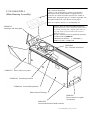
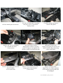
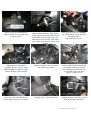
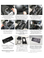
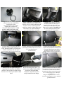
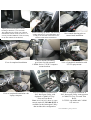
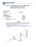
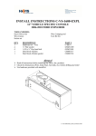
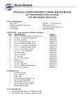
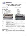
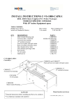
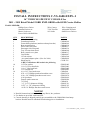
INSTALL INSTRUCTIONS C-VS-1600-EXPL-1
16” VEHICLE SPECIFIC CONSOLE for
2011 - 2015 Retail Model FORD EXPLORER with OEM Center Shifter
TOOLS NEEDED:
Phillips Screw Driver
Standard Socket set
Metric Socket set
Power Drill with Drill Bits
QTY
1
1
1
1
1
1
1
1
1
2
1
1
10
6
4
8
10
4
2
2
4
2
1
2
2
Wire Cutters
T-20 Torx Bit
90° Scribe
DESCRIPTION
Main Console Housing
Front hump bracket
Front shifter platform (attaches to hump bracket)
Rear mount bracket
Driver side trim panel
Passenger side trim panel
Top / Forward trim bezel
Rear control cover plate
Cup Holder
12 volt sockets
Aux panel adaptor plate (New for 2014)
Hardware kit
C-HK-176 Hardware Kit includes the following
1/4” Flat washer
1/4 x 3/4” Hex head bolt
1/4 x 1” Hex head bolt
1/4” serrated nut
# 8 x 3/8” Torx head screw
8/32 x 1/2” Phillips pan head machine screw
# 10 x 3/4” Phillips pan sheet metal screw
# 10 Speed nut
Female spade connector
7/8” Plug
3.5” (3-1/2”) diameter O-Ring
1.875” (1- 7/8”) diameter O-Ring
#8 X 1/4" Phillips flat sheet metal screw
Wire Crimping tool
Adjustable Wrench
Small Screw Drivers
PART #
CM004244
CM004246
CM004239
CM004237
CM004236
CM004248
CM004317
CM001407
CM216560
CM005898
C-HK-176
GSM31005
GSM33001
GSM33002
GSM30023
CM86508
GSM33110
GSM34170
GSM30199
GSM20224
CM86430
GSM31331
GSM31335
GSM33178
NOTES!
Read all instructions before installing any Havis, Inc. products.
Use hardware provided with install kit.
Console housing is shipped partially pre-assembled to the CM004244 front hump
bracket. Bracket must be unbolted from housing prior to installation.
C-VS-1600-EXPL-1_INST_7-12.docx
Optional # CM005159 (Sold separately)
Top / Forward Trim Bezel
-Allows C-VS-1600-EXPL-1 console to fit into Ford
Interceptor Utility with Standard or Upgrade Interior.
-Converts 16” inches of usable space into 24” inches of
usable space. If using this part, a C-CUP2-I cup holder will
be required if desired. **See Photos on last page**
C-VS-1600-EXPL-1
(Main Housing Assembly)
Also see complete console # C-VS-2400-INUT-1
Adaptor plate for 2014 Ford Retail Explorer.
Adapts the smaller (2014) OEM aux input panel to
fit console forward plate. Adaptor plate with “O”
ring and mount screws included with consoles
MFG after 9/1/13.
Retrofit / Adaptor kit can be purchased separately
if needed. Part # CM005919
CM005919 kit includes – 1 – CM005898, 1 GSM31335 and 2 - GSM33178
CM004236
Passenger side trim panel
CM004248
Top / Forward Trim Bezel
CM004237 Driver side cover panel
CM004244 Front hump bracket
CM004246 Front shifter platform
Main Console Housing
CM004317
Rear control cover plate
(not shown)
CM004239
Rear mount bracket (inside console)
C-VS-1600-EXPL-1_INST_7-12.docx
O.E.M. console prior to removal
Remove one (1) screw holding
top / forward trim bezel.
(7mm socket)
Remove Aux input jack from trim
bezel assembly.
To be reused later.
Lift arm rest and remove (unsnap)
trim piece with 12 volt socket.
Unplug socket.
Carefully unsnap and remove
console side panels
Carefully remove / unsnap trim
bezel and remove terrain
management switch or accessory
pocket. It helps to turn ignition on
and move shift lever knob rearward.
Carefully unsnap shifter boot from
underside of trim bezel.
Unplug Aux input jack and 12 volt
socket. O.E.M. plugs and wiring
will be reused later.
Remove two (2) screws for rear
storage pocket latch bracket.
(7mm socket)
Remove storage pocket.
Note: There is a sensor attached
to the bottom of pocket that must
be unplugged.
C-VS-1600-EXPL-1_INST_7-12.docx
Remove sensor from bottom of
storage pocket. To be reused later.
(10mm socket)
Carefully unclip shifter cable from
shifter mount assembly. This is done
by pushing the two white tabs forward
and sliding cable towards driver side.
Both tabs need to be done at the same
time. Small screw drivers can be used
for this.
Using a flat screwdriver, carefully
pop off the shifter cable end from
the linkage stud.
Pop toward driver side.
Unplug harness from shifter
assembly. Remove four (4) bolts
holding shifter assembly to plastic
console housing. (8mm socket)
Shifter assembly is now removed
and will be reused later.
Total of eight (8) bolts holding the
main plastic console housing to
floor must now be removed. Two
(2) forward driver side bolts
shown. (10mm socket)
Passenger side / side bolt shown.
Detach carpet from side of console.
Passenger side / rear bolt shown.
Unplug main harness from console
base at passenger side front.
C-VS-1600-EXPL-1_INST_7-12.docx
Remove console housing.
Detach O.E.M. harness from
console housing. To be reused.
A 90° scribe works well for
popping out harness clips.
Remove HVAC controls from rear
console housing if you desire to reuse
it in the new console. The plug for
this can remain disconnected if
controls are not used.
Remove O.E.M. forward and
middle brackets from transmission
hump. Save hardware.
(8mm socket)
Mount new # CM004244 front
hump bracket to transmission
hump with O.E.M screws
previously removed.
(8mm socket)
Attach # CM004246 front shifter
platform to hump bracket with four
(4) 1/4 x 3/4 Hex head bolts, lock
washers and flat washers.
(7/16 wrench)
Route harnesses over bracket
and reconnect to sensor.
Console harness shown removed.
Note: Small harness for cup holder
lights does not need to be removed.
With battery disconnected,
temporarily unplug harnesses from
OEM sensor and detach two (2)
harness clips from transmission hump.
Attach previously removed sensor
onto # CM004239 rear mount
bracket studs and 1/4 serrated nuts.
Plugs facing rear of vehicle.
(7/16 wrench)
C-VS-1600-EXPL-1_INST_7-12.docx
Attach # CM004239 rear mount
bracket to existing O.E.M. rear
floor bracket with two (2)
previously removed bolts. (10mm)
Sensor faces down.
Carefully place # CM004248
Top / forward trim bezel.
Do not screw down yet.
Attach the supplied 3-1/2” diameter ORing to the back of the Auxiliary panel
as shown.
This helps make a snug fit when
snapped into the console bezel.
Note: This method also works for other
Auxiliary panels such as the MyFord
Touch system
Place main console housing into
vehicle and loosely attach it to the
mounting brackets with six (6) 1/4 x
3/4 hex bolts and flat washers. (7/16)
Note: Carpet tucks between hump
bracket and console side panels.
Place shifter assembly into console.
Do not bolt in yet.
Place previously removed O.E.M.
harness inside console housing.
Reconnect plugs as needed.
Now attach shifter assembly to
shifter platform with four (4) 1/4 x
1” hex head bolts and flat washers.
(7/16 socket)
Reattach O.E.M. shifter cable to
original locations.
Route terrain management switch
and aux plugs to new mounting
locations. Cut off O.E.M. 12 volt
plug and attach supplied 1/4
female spade connectors on wires.
Adaptor plate for 2014 Ford Retail
Explorer.
Adapts the smaller (2014) OEM aux
input panel to fit console forward
panel. Adaptor with “O” ring and
mount screws included with consoles
MFG after 9/1/13.
Attach 1-7/8” diameter “O” ring to
the OEM aux panel and snap into
adaptor plate. Attach plate assembly
to console forward bezel with #8 x
1/4" Phillips flat head screws.
(2014 Premium Aux panel shown)
(2014 Standard Aux panel shown)
C-VS-1600-EXPL-1_INST_7-12.docx
Using one (1) 1-3/4” O-Ring supplied,
attach it to the back of the terrain
management switch
This helps make a snug fit when
snapped into console bezel.
** If your vehicle only has a round
accessory pocket, the pocket will
need to be glued into the round hole.
Attach supplied 12 volt socket into
7/8 hole in console bezel. Plug 12 volt
positive wire to center connector and
negative wire to outboard ground
connector. Attach original plugs onto
TM switch, Aux panel and snap or
screw them into place as shown.
Carefully snap shifter boot into
mounting tabs on underside of
bezel. Use six (6) # 8 x 3/8” torx
head screws and attach bezel to
front end of console. Carefully line
up bezel with front ends of side
extrusions. (T-20 torx bit)
Cut off O.E.M. 12 volt plug and attach
supplied 1/4 female spade connectors on
wires. Attach supplied 12 volt socket into
7/8 hole in passenger side trim panel.
Insert supplied 7/8 plugs into unused hole.
Loosely attach each forward side trim
panel onto console with two (2) # 8 x
3/8” torx head screws.
(T-20 torx bit)
Position side trim panel up tight to
dash. You should also lift front end
of console housing to get the best
possible fit. Drill 1/8” hole into
plastic dash at forward mount hole.
Remove side trim panel and place
supplied # 10 speed nut onto drilled
location. This provides a sturdy mount
for trim screw. Same procedure on both
sides.
Before attaching trim panels, you
will need to slightly bend pointed
part shown inward behind
extrusion. Adjustable wrench
easily bends this metal flange.
Reattach each forward side trim panel
onto console with two (2) # 8 x 3/8” torx
head screws. (T-20 torx bit) Attach
forward end of panel to speed nut with #
10 x 3/4 sheet metal screw. (Phillips
screwdriver)
Plug 12 volt positive wire to center
connector and negative wire to outboard
C-VS-1600-EXPL-1_INST_7-12.docx
ground connector.
Adjust position and tighten console
housing to brackets. (7/16 wrench)
This photo shows O.E.M. rear controls
mounted in console. Four (4) 8/32 x 1/2”
screws provided. Note: It is not necessary
to use the controls if not desired.
View of completed installation
View of completed installation with
Laptop computer.
Before inserting cup holder, run necessary
wiring and wire tie as needed. Make sure
wiring is not stressed or that it does not
interfere with shifter mechanism.
Console includes mounting
provisions for side mounted
C-HDM-204 or C-TCB-7 computer
mount brackets.
View of completed installation in
2013 Interceptor Utility with
Optional # CM005159 Top /
Forward Trim Bezel
Note: As of 10//4/13, there is a new
console model C-VS-2400-INUT-1
available for the Interceptor Utility
that includes this configuration.
New console housing prior to
control head installation.
View of completed installation with
UT-X Laptop mount.
View of completed installation in
2013 Interceptor Utility with Optional
# CM005159 Top / Forward Trim
Bezel,
C-CUP2-I cup holder and C-ARM103 arm rest.
C-VS-1600-EXPL-1_INST_7-12.docx