1
option is present, this selection will deactivate the standard XLR inputs and enable the dedicated 4
pin 130V XLR inputs. In this mode, the 48V pushbutton switch will turn on the 130V power supply.
Phase reverse and -20dB pad are available in this mode. The dual balanced XLR outputs carry the
output signal. Note: this option is no longer available.
SETTING THE GAIN
First, turn the gain control fully counter-clockwise and check that the 48V phantom power is off.
Connect a microphone and then turn on the phantom power if required. When sending a signal to
a recorder, converter or interface that has fixed input levels, simply increase the gain until the optimum recording level is reached. If the peak indicator flashes red excessively with the gain control in
the fully counterclockwise position, engage the -20dB attenuator.
When sending a signal to a recorder with an input attenuator (i.e. the record level control on a DAT
or CDR recorder) use the following procedure: With the sound source present, turn the gain control
clockwise until the peak LED begins flashing red, then reduce the gain until the red stops flashing. Since red indicates a peak level which is 12dB before preamplifier clipping (6dB in unbalanced
mode), it is OK for it to come on periodically during recording. If peak indicator flashes red excessively with the gain control in the fully counterclockwise position, engage the -20dB attenuator. Now
adjust the recorder input control for the optimum recording level.
Ribbon Mic Mode
Selecting the ribbon mic position on the input mode switch optimizes the channel for ribbon microphones by boosting the gain by 10dB while disabling 48V phantom power and optimizing the mic
input impedance. Before activating ribbon mic mode, make sure the channel’s gain is fully down
(counter-clockwise) and 48V phantom power is off. Now simply select ‘ribbon’ input mode and turn
the gain control upwards until the proper recording level is achieved.
If you press the 48V phantom switch while the ribbon switch is engaged, the mic power will not turn
on. However, if the 48V phamtom switch remains depressed and the input mode switch becomes
inadvertently changed to ‘48V’, 48V phantom will consequently be activated, which can potentially
harm a ribbon your microphone if it is still connected to the input. If the 48V phantom power switch
is turned of and then the ribbon mode is selected, the preamplifier will wait until the phantom power voltage has completely discharged and then the ribbon mode will activate automatically.
An additional benefit of the ribbon mic mode is that the input DC blocking capacitors are relay bypassed to further simplify the m201’s signal path. Incidentally, the ribbon mode works very well with
many lower output dynamic microphones as well as ribbon types.
M-S recording
In M-S mode the m201 accepts the Mid signal in channel 1 and the Side signal in channel 2. The LEFT
channel output connector provides the “sum” of the inputs and the RIGHT channel output connector
provides the “difference” of the inputs. In M-S mode, the M-S width control adjust the ratio of Mid
signal to Side signal in the dedicated M-S outputs. The LEFT and RIGHT M-S outputs are always active which allows the user to record the discreet Mid and Side signals from the preamplifier Channel
8
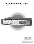
grace design m201
owner’s manual