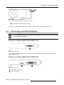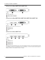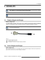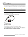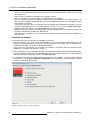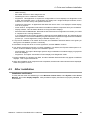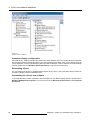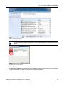
1
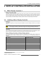
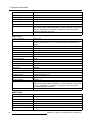
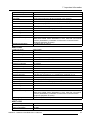
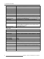
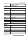
Display Controller
User Guide
Windows 7 and Windows 8.1
K5905271/06
11/09/2014
Barco nv
President Kennedypark 35, 8500 Kortrijk, Belgium
Phone: +32 56.23.32.11
Fax: +32 56.26.22.62
Support: www.barco.com/esupport
Visit us at the web: www.barco.com
Printed in Belgium
Table of contents
TABLE OF CONTENTS
1. Welcome! .......................................................................................... 3
1.1
1.2
About the product .. .. .. .. .. .. .. .. .. .. .. .. .. .. .. .. .. .. .. .. .. .. .. .. .. .. .. .. .. .. .. .. .. .. .. .. .. .. .. .. .. .. .. .. .. .. . 3
What’s in the box. .. .. .. .. .. .. .. .. .. .. .. .. .. .. .. .. .. .. .. .. .. .. .. .. .. .. .. .. .. .. .. .. .. .. .. .. .. .. .. .. .. .. .. .. .. .. . 3
2. Display Controller installation ................................................................ 5
2.1
2.2
2.3
2.4
Which Display Controller ? .. .. .. .. .. .. .. .. .. .. .. .. .. .. .. .. .. .. .. .. .. .. .. .. .. .. .. .. .. .. .. .. .. .. .. .. .. .. .. .. .. .
Installing a Barco Display Controller . .. .. .. .. .. .. .. .. .. .. .. .. .. .. .. .. .. .. .. .. .. .. .. .. .. .. .. .. .. .. .. .. .. .. .. .
Installation procedure.. .. .. .. .. .. .. .. .. .. .. .. .. .. .. .. .. .. .. .. .. .. .. .. .. .. .. .. .. .. .. .. .. .. .. .. .. .. .. .. .. .. .. .. .
Connecting your Barco Displays . .. .. .. .. .. .. .. .. .. .. .. .. .. .. .. .. .. .. .. .. .. .. .. .. .. .. .. .. .. .. .. .. .. .. .. .. .. .
5
5
6
7
3. Dongles ............................................................................................. 9
3.1
3.2
3.3
3.4
Passive Single-Link Dongle . .. .. .. .. .. .. .. .. .. .. .. .. .. .. .. .. .. .. .. .. .. .. .. .. .. .. .. .. .. .. .. .. .. .. .. .. .. .. .. .. . 9
Active Single-Link Dongle . .. .. .. .. .. .. .. .. .. .. .. .. .. .. .. .. .. .. .. .. .. .. .. .. .. .. .. .. .. .. .. .. .. .. .. .. .. .. .. .. .. . 9
Dual-Link Dongle. .. .. .. .. .. .. .. .. .. .. .. .. .. .. .. .. .. .. .. .. .. .. .. .. .. .. .. .. .. .. .. .. .. .. .. .. .. .. .. .. .. .. .. .. .. .. . 10
Common cases. .. .. .. .. .. .. .. .. .. .. .. .. .. .. .. .. .. .. .. .. .. .. .. .. .. .. .. .. .. .. .. .. .. .. .. .. .. .. .. .. .. .. .. .. .. .. .. . 11
4. Driver and software installation .............................................................. 23
4.1
4.2
4.3
4.4
Driver and software installation prerequisites . .. .. .. .. .. .. .. .. .. .. .. .. .. .. .. .. .. .. .. .. .. .. .. .. .. .. .. .. .. .. . 23
Installing the Barco MXRT drivers and software.. .. .. .. .. .. .. .. .. .. .. .. .. .. .. .. .. .. .. .. .. .. .. .. .. .. .. .. .. . 23
After installation .. .. .. .. .. .. .. .. .. .. .. .. .. .. .. .. .. .. .. .. .. .. .. .. .. .. .. .. .. .. .. .. .. .. .. .. .. .. .. .. .. .. .. .. .. .. .. . 25
Silent installation of drivers and software.. .. .. .. .. .. .. .. .. .. .. .. .. .. .. .. .. .. .. .. .. .. .. .. .. .. .. .. .. .. .. .. .. . 28
5. Configuring Windows ........................................................................... 31
5.1
5.2
5.3
Configuring SingleView.. .. .. .. .. .. .. .. .. .. .. .. .. .. .. .. .. .. .. .. .. .. .. .. .. .. .. .. .. .. .. .. .. .. .. .. .. .. .. .. .. .. .. . 31
Configuring Barco Displays with the Windows Display Control Panel.. .. .. .. .. .. .. .. .. .. .. .. .. .. .. .. .. . 31
Configuring software rotation . .. .. .. .. .. .. .. .. .. .. .. .. .. .. .. .. .. .. .. .. .. .. .. .. .. .. .. .. .. .. .. .. .. .. .. .. .. .. .. . 31
6. Conference CloneView .......................................................................... 33
6.1
6.2
6.3
6.4
What is Conference CloneView ? .. .. .. .. .. .. .. .. .. .. .. .. .. .. .. .. .. .. .. .. .. .. .. .. .. .. .. .. .. .. .. .. .. .. .. .. .. . 33
Configuration . .. .. .. .. .. .. .. .. .. .. .. .. .. .. .. .. .. .. .. .. .. .. .. .. .. .. .. .. .. .. .. .. .. .. .. .. .. .. .. .. .. .. .. .. .. .. .. .. . 33
Notification icon .. .. .. .. .. .. .. .. .. .. .. .. .. .. .. .. .. .. .. .. .. .. .. .. .. .. .. .. .. .. .. .. .. .. .. .. .. .. .. .. .. .. .. .. .. .. .. . 34
Tools available on the cloned display .. .. .. .. .. .. .. .. .. .. .. .. .. .. .. .. .. .. .. .. .. .. .. .. .. .. .. .. .. .. .. .. .. .. .. . 35
7. Important information ........................................................................... 37
7.1
7.2
7.3
7.4
7.5
7.6
Safety information.. .. .. .. .. .. .. .. .. .. .. .. .. .. .. .. .. .. .. .. .. .. .. .. .. .. .. .. .. .. .. .. .. .. .. .. .. .. .. .. .. .. .. .. .. .. . 37
Environmental information .. .. .. .. .. .. .. .. .. .. .. .. .. .. .. .. .. .. .. .. .. .. .. .. .. .. .. .. .. .. .. .. .. .. .. .. .. .. .. .. .. . 37
Regulatory compliance information .. .. .. .. .. .. .. .. .. .. .. .. .. .. .. .. .. .. .. .. .. .. .. .. .. .. .. .. .. .. .. .. .. .. .. .. . 39
Explanation of symbols .. .. .. .. .. .. .. .. .. .. .. .. .. .. .. .. .. .. .. .. .. .. .. .. .. .. .. .. .. .. .. .. .. .. .. .. .. .. .. .. .. .. .. . 39
Legal disclaimer .. .. .. .. .. .. .. .. .. .. .. .. .. .. .. .. .. .. .. .. .. .. .. .. .. .. .. .. .. .. .. .. .. .. .. .. .. .. .. .. .. .. .. .. .. .. .. . 41
Technical specifications . .. .. .. .. .. .. .. .. .. .. .. .. .. .. .. .. .. .. .. .. .. .. .. .. .. .. .. .. .. .. .. .. .. .. .. .. .. .. .. .. .. .. . 41
K5905271 DISPLAY CONTROLLER 11/09/2014
1
Table of contents
2
K5905271 DISPLAY CONTROLLER 11/09/2014
1. Welcome!
1. WELCOME!
1.1
About the product
Display Controller
Thank you for choosing this Barco Display Controller!
Barco’s state-of-the-art Display Controllers deliver the performance, quality and stability required for today’s advanced medical imaging applications. The powerful boards ensure ultra-fast and smooth image
loading, roaming and manipulation of images in every resolution.
Use the instructions in this guide to install your Barco Display Controller.
1.2
What’s in the box
Contents
Your Barco Display Controller comes with:
•
•
•
•
This Barco Display Controller User Guide
2 Single-Link Dongles are included with the MXRT-4500, MXRT-5400, MXRT-5500, MXRT-7400 &
MXRT-7500.
1 Single-Link Dongle and 1 low-profile bracket are included with the MXRT-2400 & MXRT-2500.
1 DMS-59-to-DVI adapter cable and 1 low-profile bracket are included with the MXRT-1450 & MXRT1451.
Keep your original packaging. It is designed for this Display Controller and is the ideal
protection during transport and storage.
K5905271 DISPLAY CONTROLLER 11/09/2014
3
1. Welcome!
4
K5905271 DISPLAY CONTROLLER 11/09/2014
2. Display Controller installation
2. DISPLAY CONTROLLER INSTALLATION
2.1
Which Display Controller ?
Display Controller range
Your Barco medical display is compatible with a large range of Barco and non-Barco Display Controller
boards. Depending on the order details, the display can be delivered with or without a Display Controller.
If you are installing a Barco Display Controller, please follow the installation instructions in this section. If
you are installing a non-Barco display controller, please consult its corresponding documentation.
2.2
Installing a Barco Display Controller
Guidance
This chapter will guide you through the physical installation of a Barco Display Controller for your display
system.
WARNING: Wear a grounded, protective ESD strap when handling or during installation
of the Display Controller. Electrostatic charges can damage the Display Controller.
Overview
Prior to installing the Barco Display Controller(s) for your Barco Display System in your workstation, please
take a few minutes to familiarize yourself with the Display Controller(s) and the PCIe slots.
Types of Display Controllers for Barco Display Systems
The following models of Barco Display Controllers are available for your display system. Please check
which of the following models is delivered with your system and follow the corresponding installation instructions:
Barco Model
Compatible PCIe Slot
Barco MXRT-1450
x11, x8, x16
Barco MXRT-1451
x1 1, x8, x16
Barco MXRT-2400
x16
Barco MXRT-2500
x16
Barco MXRT-45002
x16
Barco MXRT-5400
x16
Barco MXRT-5450
x16
Barco MXRT-5500
x16
Barco MXRT-5550
x16
Barco MXRT-7400
x16
Barco MXRT-7500
x16
1. Recommended PCIe slot. You can also use x16 & x8 slots for x1 boards.
2. Available in limited markets
K5905271 DISPLAY CONTROLLER 11/09/2014
5
2. Display Controller installation
Which PCIe slot to use
The table above lists the various Display Controller model(s) available for your Barco Display System and
the recommended PCIe slot to use for optimum performance. The figure below shows the different types
of PCIe slots that can be used.
1
2
3
Image 2-1
Examples of PCIe slots
2.3
1
x16 slot
2
x8 slot
3
x1 slot
Installation procedure
How to install
The following instructions will take you step by step through the installation of the Barco Display Controller(s) for your Barco Display System.
1. If you are not going to use your old Display Controller, uninstall its drivers and software.
Warning:Wear a grounded, protective ESD strap when handling or during installation of the Display
Controller. Electrostatic charges can damage the Display Controller.
2. Turn off the computer, display(s), and other peripheral devices.
3. Unplug the computer’s power cord and disconnect all cables from the back of your computer.
Warning:Wait approximately 20 seconds after unplugging the power cord before disconnecting a peripheral or removing a component from the motherboard to avoid possible damage to the
motherboard.
4. Remove the computer cover. If necessary, consult your computer’s manual for instructions.
5. If necessary, unscrew or unfasten and remove any existing display controller(s) from your computer.
Tip: If you are using a motherboard containing an on-board graphics solution and do not intend to
use it as part of a multiple-display setup, disable it either in the computer’s System Set-up utility
(BIOS) or the Windows device manager.
6. Locate the appropriate slot and, if necessary, remove the metal back-plate cover(s).
7. Align the Barco Display Controller(s) for your Barco Display System with the slot(s) and press it(them)
in firmly until the card(s) is(are) fully seated.
Tip: The next step applies only to the MXRT-7400 & MXRT-7500.
8. Connect the power cable to the 6-pin power connection on the Display Controller. Make sure the cables
are not interfering with anything inside the computer (for example, a cooling fan).
6
K5905271 DISPLAY CONTROLLER 11/09/2014
2. Display Controller installation
1
Image 2-2
Power connection for the MXRT-7400 & MXRT-7500 controllers
1
6-pin graphics controller power cable
9. Screw in or firmly fasten the Display Controller. Replace and secure the computer cover.
2.4
Connecting your Barco Displays
For a detailed description of the display installation and signal connection, please refer
to the Display User Guide.
IO-Panel for the Barco MXRT-1450 & MXRT-1451
1
Image 2-3
MXRT-1450 & MXRT-1451
1
DMS-59 connector provides DVI-I / Head 1 & Head 2 output connections through included the
Y-adapter cable.
IO-Panel for the Barco MXRT-2400 & MXRT-2500
1
2
Image 2-4
MXRT-2400 & MXRT-2500
1
DisplayPort Connection
2
DVI-I Connection
K5905271 DISPLAY CONTROLLER 11/09/2014
7
2. Display Controller installation
IO-Panel for the Barco MXRT-5450 & MXRT-5550
1
2
Image 2-5
MXRT-5450 & MXRT-5550
1
Head 1- DVI-I Connection
2
Head 2- DVI-I Connection
IO-Panel for the Barco MXRT-4500, MXRT-5400, MXRT-5500 & MXRT-7400
1
2
3
Image 2-6
MXRT-4500, MXRT-5400, MXRT-5500 & MXRT-7400
1
DisplayPort #1
2
DisplayPort #2
3
DVI-I
IO-Panel for the Barco MXRT-7500
1
2
3
4
Image 2-7
MXRT-7500
1
DisplayPort #1
2
DisplayPort #2
3
DisplayPort #3
4
DisplayPort #4
For displays with native DisplayPort input, use a native DisplayPort cable to connect the DisplayPort output
of the Display Controller to the DisplayPort input of the display. You cannot connect the DVI output of a
Display Controller to the DisplayPort input of a display.
8
K5905271 DISPLAY CONTROLLER 11/09/2014
3. Dongles
3. DONGLES
Barco dongles are specially designed to allow Barco Display Controllers with a DisplayPort output to be connected with a display with DVI input.
If video cable conversion is not required, you may bypass this section.
3.1
Passive Single-Link Dongle
Passive Single-Link
The passive Single-Link Dongle allows you to connect a display’s DVI input to the DisplayPort output of
your Barco Display Controller. It is compatible with all Barco grayscale displays and up to 2MP color
models. For color displays of 3MP and greater resolutions, the Dual-Link Dongle is necessary.
All Barco Display Controllers compatible with the DisplayPort interface come with a Single-Link Dongle by default.
1
2
Image 3-1
Single-Link dongle (supplied with system)
3.2
1
To display (Single-Link DVI)
2
To DisplayPort connector on Barco Display Controller
Active Single-Link Dongle
Active Single-Link
Barco Display Controllers are not compatible with active single-link dongles. Please use the passive dongles that are included with your Barco Display Controllers.
K5905271 DISPLAY CONTROLLER 11/09/2014
9
3. Dongles
3.3
Dual-Link Dongle
Dual-Link
The active Dual-Link Dongle also converts DisplayPort input signals to DVI output signals. However, unlike
the passive Single-Link dongle, the Dual-Link dongle allows higher resolutions (greater than 1920x1200)
on color displays.
WARNING: A Dual-Link DVI cable must be used to connect your display’s DVI connector
with the DVI connector on the Dual-Link Dongle.
The Dual-Link dongle is ordered separately.
How to install the Dual-Link Dongle
Use the following steps to install the dongle:
1. Connect the DisplayPort end of the connector to the Display Controller.
3
1
2
Image 3-2
Dual-Link dongle (ordered separately)
1
To computer’s USB port
2
To display (DVI Dual-Link)
3
To DisplayPort connector on Barco Display Controller
2. Plug in a Dual-Link DVI cable from the display to the DVI port of the dongle.
3. Connect the built-in USB power cable on the dongle to a workstation USB port.
4. If you are using QAWeb Agent version 1.10.2 or older, a separate software component is required for supporting DDC communication through the Dual-Link dongle. Run setup.exe from
Barco_DLDP2DVI_Install package after driver installation to install the SW.
10
K5905271 DISPLAY CONTROLLER 11/09/2014
3. Dongles
1
3
2
4
Image 3-3
Dual-Link Dongle installation
3.4
1
Up to 3MP color
2
9’ Barco DVI cable
3
Dual-Link DP to DVI adapter
4
USB power connector
Common cases
MXRT-2400 & MXRT-2500
3
1
3
2
Image 3-4
All grayscale or 2MP color diagnostic displays
1
DisplayPort connection with single-link dongle
2
DVI-I connection
3
Grayscale diagnostic display or Color 2MP diagnostic display
K5905271 DISPLAY CONTROLLER 11/09/2014
11
3. Dongles
4
3
1
2
Image 3-5
DVI 6MP Color Diagnostic display or 3MP Color display
1
DisplayPort connection with dual-link dongle
2
DVI-I connection
3
USB power to computer
4
DVI 6MP Color Diagnostic display or 3MP Color display
4
3
1
2
Image 3-6
DVI Color Navigation display and any Grayscale or 2MP Color Diagnostic display
12
1
DisplayPort connection with single-link dongle
2
DVI-I connection
3
DVI Color Navigation display
4
Grayscale or 2MP Color Diagnostic display
K5905271 DISPLAY CONTROLLER 11/09/2014
3. Dongles
MXRT-4500, MXRT-5400, & MXRT-5500
DVI Navigation display and all Grayscale or 2MP Color Diagnostic displays
4
4
5
1
2
3
Image 3-7
DVI Navigation display and all Grayscale or 2MP Color Diagnostic displays
1
DisplayPort with single-link dongle
2
DisplayPort with single-link dongle
3
DVI-I
4
Grayscale Diagnostic display or 2MP Color Diagnostic display
5
Color Navigation display
5
5
4
1
2
3
Image 3-8
DisplayPort Navigation display and all Grayscale or 2MP Color Diagnostic displays
K5905271 DISPLAY CONTROLLER 11/09/2014
13
3. Dongles
1
DisplayPort #1
2
DisplayPort connection with single-link dongle
3
DVI-I
4
Color Navigation display
5
Grayscale Diagnostic display or 2MP Color Diagnostic display
6
5
4
1
2
3
Image 3-9
DVI Navigation display and 6MP Color Diagnostic display or 3MP Color displays
1
DisplayPort connection with single-link dongle
2
DisplayPort connection with dual-link dongle
3
DVI-I
4
USB power to computer
5
Color Navigation display
6
6MP Color Diagnostic display or 2 x 3MP Color displays
6
5
4
1
2
3
Image 3-10
DisplayPort Navigation display and 6MP Color Diagnostic display or 3MP Color displays
14
K5905271 DISPLAY CONTROLLER 11/09/2014
3. Dongles
1
DisplayPort #1
2
DisplayPort connection with dual-link dongle
3
DVI-I
4
USB power to computer
5
Color Navigation display
6
6MP Color Diagnostic display or 2 x 3MP Color displays
MXRT-7400
4
4
5
1
2
3
Image 3-11
DVI Navigation display and all Grayscale or 2MP Color Diagnostic displays (see Tip)
1
DisplayPort connection with single-link dongle
2
DisplayPort connection with single-link dongle
3
DVI-I
4
Grayscale Diagnostic display or 2MP Color Diagnostic display
5
Color Navigation display
K5905271 DISPLAY CONTROLLER 11/09/2014
15
3. Dongles
5
5
4
1
2
3
Image 3-12
DisplayPort Navigation display and all Grayscale or 2MP Color Diagnostic displays (see Tip)
1
DisplayPort #1
2
DisplayPort connection with single-link dongle
3
DVI-I
4
Color Navigation display
5
Grayscale Diagnostic display or 2MP Color Diagnostic display
Diagnostic displays must have matching resolutions.
5
6
4
4
1
2
3
Image 3-13
DVI Navigation display and 6MP Color Diagnostic display or 3MP Color displays
16
K5905271 DISPLAY CONTROLLER 11/09/2014
3. Dongles
1
DisplayPort connection with dual-link dongle
2
DisplayPort connection with dual-link dongle
3
DVI-I
4
USB power to computer
5
6MP Color Diagnostic display or 2 x 3MP Color displays
6
Color Navigation display
6
5
4
1
2
3
Image 3-14
DisplayPort Navigation display and 6MP Color Diagnostic display or 3MP Color displays
1
DisplayPort connection with single-link dongle
2
DisplayPort connection with dual-link dongle
3
DVI-I
4
USB power to computer
5
Color Navigation display
6
6MP Color Diagnostic display or 2 x 3MP Color displays
K5905271 DISPLAY CONTROLLER 11/09/2014
17
3. Dongles
MXRT-7500
2
2
3
4
1
Image 3-15
DVI Navigation display and Dual-head DVI Grayscale displays with an optional DisplayPort 3D display (see Tip).
1
DisplayPort #1 through #4
2
Grayscale Diagnostic display (DVI)
3
3D Display (DP): this is optional
4
Color Navigation display
The Grayscale Diagnostic displays must have matching resolutions.
18
K5905271 DISPLAY CONTROLLER 11/09/2014
3. Dongles
2
3
2
4
1
Image 3-16
DVI Navigation display and Dual-head DisplayPort Grayscale displays with an optional DVI 3D display
1
DisplayPort #1 through #4
2
Grayscale Diagnostic display (DP)
3
3D Display (2MP Color DVI): this is optional
4
Color Navigation display
K5905271 DISPLAY CONTROLLER 11/09/2014
19
3. Dongles
3
4
5
2
2
1
Image 3-17
DisplayPort Navigation display and DVI 6MP Color Diagnostic display or 3MP Color displays with an optional third DVI display
20
1
DisplayPort #1 through #4
2
USB power to computer
3
6MP Color Diagnostic display or 2 x 3MP Color Diagnostic DVI (e.g. MDCC-6130)
4
Color Navigation display (DP)
5
Color Navigation display (DVI): this is optional
K5905271 DISPLAY CONTROLLER 11/09/2014
3. Dongles
3
2
4
1
Image 3-18
DisplayPort Navigation display and DisplayPort 6MP Color Diagnostic display or 3MP Color displays with an optional DVI 3D display
1
DisplayPort #1 through #4
2
Color Navigation DP display (e.g. MDRC-2124)
3
6MP Color Diagnostic display or 2 x 3MP Color Diagnostic DP display (e.g. MDCC-6230)
4
3D Display (2MP Color DVI): this is optional
K5905271 DISPLAY CONTROLLER 11/09/2014
21
3. Dongles
22
K5905271 DISPLAY CONTROLLER 11/09/2014
4. Driver and software installation
4. DRIVER AND SOFTWARE
INSTALLATION
4.1
Driver and software installation prerequisites
Prerequisites
To install or remove the drivers, software, or documentation you must be logged on as
a user with administrator privileges.
Your operating system must be installed and running before you can install the driver, software and documentation for the Barco Display Controller(s) for your Barco Display System.
Before you begin, make sure that all of your Barco Displays are connected to the appropriate Display
Controller(s) in your system.
4.2
Installing the Barco MXRT drivers and software
Introduction
This chapter will guide you through the installation of the drivers, software and documentation associated
with your Barco Display System or Barco Display Controller(s).
The installation dialog will display in English if your operating system’s language is not
supported.
This process applies to the following versions of Windows:
•
•
•
•
Windows
Windows
Windows
Windows
7 32-bit
7 64-bit
8.1 32-bit
8.1 64-bit
For optimal system performance, Barco recommends installing no more than two
drivers on a system at one time. If the configuration will require three drivers, the Barco
Driver Installer will alert the user to replace one board to eliminate one of the drivers.
You will need to install the Barco Display Controller system drivers and software in the following cases:
K5905271 DISPLAY CONTROLLER 11/09/2014
23
4. Driver and software installation
•
•
•
After you have installed the Barco Display Controller(s) for your Barco Display System in your system
for the first time.
After you have reinstalled or upgraded your operating system.
When you upgrade to a newer version of the MXRT driver and software.
You do not need to manually uninstall an existing driver before updating to the current version. The
Barco Product Installation Wizard will detect any prior installations and start the uninstallation process
automatically if necessary.
If you have a previous version of Conference CloneView application installed in the system, you need
to terminate the application prior to installing the new version. To do so, bring up Barco Clone Display(s) configuration window, select Stop Cloning, and close the window.
When there is a non-Barco board in the system, we recommend that you first install the driver for the
non-Barco board before installing the Barco driver.
After each driver installation, you should reboot the system before proceeding with the installation of
another driver.
Installation procedure
The following will guide you through the installation procedure:
1. Start your system. If you have a fresh OS installation, or you have uninstalled an existing driver, the
OS may automatically install an inbox driver from the Windows 7 driver store, either an AMD driver or
a standard VGA driver, for the Barco Display Controller(s).
If this occurs, the OS prompts you to restart your computer, click Yes to allow the automatic driver
installation to complete and reboot the system.
2. Launch the Barco Product Installation Wizard. The installation Wizard should start automatically when
you insert the Barco Display System Installation DVD into your computer’s DVD drive. If the installation
does not start, in the "auto play" window, click Run setup.exe.
3. To accept the installation of default software components, click on Next. To custom select software
components, click on Select Software Components and the following screen will appear, allowing
selection of individual components.
Image 4-1
Software component options for custom installation
24
K5905271 DISPLAY CONTROLLER 11/09/2014
4. Driver and software installation
-
-
MXRT driver(s)
BarcoMed Self Exam: Barco diagnostic tool
QAWebAgent: Barco calibration software2
SingleView: This application is required to configure Barco Fusion displays into SingleView mode
or back into DualView mode. In SingleView, the display has a single landscape resolution, and in
DualView, it has two side-by-side portrait resolutions.
Conference CloneView: An application that allows the user to clone 1 or 2 displays to a third display,
such as a projector.
Driver Cleaner: An application that will remove all Barco software components from your workstation.
Display Installer: This file allows Windows to recognize Barco displays.
Microsoft Hotfix for KB2496400: Resolved the issue that monitor configuration is lost after you restart
a computer that is running Windows 7.
In a configuration that includes an MXRT-1150/2150 and other MXRT boards, two separate drivers
will be installed. The master installation program will make two passes through the driver installation
process (i.e. License Agreement, Verify Installation Options, etc.).
4. If a previous installation of an MXRT driver exists, the installation wizard will detect it and guide you
through the uninstallation process if necessary.
5. Click Yes to accept the driver’s License Agreement, and then Next to continue.
6. You will be prompted for Express or Custom Installation. By default, the Express Install option is selected. Custom Installation prompts two installation options:
- 30-bit Desktop: This option allows high dynamic range visualization of medical imaging on grayscale
and color displays.
- SingleView: This option sets all Barco Fusion displays into SingleView mode.
7. During installation, the desktop may flash, and the Installation Wizard window may appear on different
displays. This is expected behavior.
8. When the installation of all components has completed, the automatic reboot window will be displayed.
Allow the system to reboot.
4.3
After installation
Installation verification
To verify that the driver was installed, go to the Windows Control Panel, select System, select Device
Manager, then select Display Adapters. Verify that Barco Display Controllers are properly identified, as
shown below:
K5905271 DISPLAY CONTROLLER 11/09/2014
25
4. Driver and software installation
Image 4-2
Verifying driver installation
Automatic display configuration
Once the drivers, software and documentation have been installed and your system has been rebooted,
the computer should automatically detect your Barco displays and attach them to the desktop with the
correct resolution. If the computer fails to detect your Barco displays or fails to attach them to the desktop
correctly, please use the Windows Screen Resolution to set the correct resolution.
Reinstalling drivers
You can install new drivers or reinstall existing drivers at any time by using the Barco Set-up wizard on
your Barco Display System Installation DVD.
Uninstalling the drivers and software
To uninstall the Barco drivers, software or documentation for your Barco Display System, please use the
Windows Add/Remove Programs. This can be found in the Windows Control Panel under Programs
& Features.
26
K5905271 DISPLAY CONTROLLER 11/09/2014
4. Driver and software installation
Image 4-3
Windows 7 Add/Remove Programs
When uninstalling the Barco MXRT drivers, the following dialog box will appear. Select
the driver listed you wish to install (driver version may be different than what is pictured
below).
Image 4-4
Barco MXRT Driver Removal Wizard
Driver Cleaner
The Barco Driver Cleaner is a tool that will remove all Barco software components from your workstation.
The application and its user guide can be found at C:\program files\Barco.
K5905271 DISPLAY CONTROLLER 11/09/2014
27
4. Driver and software installation
4.4
Silent installation of drivers and software
Pre-installation
Once a Barco driver has been pre-loaded into the driver store of a Windows 7 OS, subsequent installation
of the driver will be intervention-free.
To pre-load the driver software into the driver store, open a command shell and navigate to the appropriate
driver directory and run the PnPUtil application with the -a "add" parameter. For example:
cd d:\Barco\drivers\VS32\MXRT
pnputil -a *.inf
The PnPUtil application will parse the inf files and add the MXRT drivers to the driver store.
If this is the first installation of a Barco driver, the trust prompt will ask whether you really want to install
the driver. Check the box that says Always trust software from Barco and press OK. The PnPUtil
application will confirm the driver is loaded into the driver store.
At this point you can change to another directory and repeat this with other drivers. You will not see the
trust prompt.
If you install using wildcards, you may see an error message that the Autorun.inf was not in an expected
format. This message is normal and can be ignored.
When you have added all of the drivers that you will need to the driver store, you can create an image of
the drive, and use it for staging additional systems. All of the systems with this driver store are set up for
intervention-free silent installation.
Silent installation
For silent installation, first import the Barco published certificate into the certificate store. This certificate
can be extracted from the driver catalog file located in the driver package. Please note that the certificate
changes overtime, so we recommend extracting the current one each time.
Once imported, navigate to the Barco installation folder and execute the command setup.exe -silent.
This can be done from the command shell, from the Run command, or from a command shortcut. The
setup program will automatically install the drivers for any BarcoMed or MXRT boards that are present,
the BarcoMed Self Exam program, and QAWeb (if part of the installation package).
Configure silent install options
You can modify the setup.ini file at the Barco root folder to customize some silent install options. The
configurable options are listed in the [Custom] section of the setup.ini file.
SimplifiedFinishPage:
•
•
If set to Yes, only the Finish button appears on the final installation page.
If No (default), reboot buttons and show document check boxes are also shown.
Reboot:
•
•
If set to Yes (default), the installer will prompt the user or launch a timer to reboot following software
installation.
If No, the prompt/timer is not shown.
DisableCalibrationSoftwareText:
•
•
If set to Yes (default), QAWeb software is installed.
If No, the user can select installation of either QAWeb and/or MediCal Pro, if present.
IgnoreInstallFailureOnReboot:
•
•
If set to Yes, the system will disregard any installation failures and proceed to auto-reboot.
If No (default), the auto-boot is disable if installation failures are detected.
DisableQAWebScripts:
28
K5905271 DISPLAY CONTROLLER 11/09/2014
4. Driver and software installation
•
•
If set to Yes, QAWeb will auto-start.
If No (default), scripts will prevent QAWeb from launching until after the reboot.
NeverForceUninstall:
•
•
If set to Yes, the installer will not require the user to uninstall previous Barco drivers.
If No (default), the installer prompts the user to uninstall pre-existing drivers.
K5905271 DISPLAY CONTROLLER 11/09/2014
29
4. Driver and software installation
30
K5905271 DISPLAY CONTROLLER 11/09/2014
5. Configuring Windows
5. CONFIGURING WINDOWS
5.1
Configuring SingleView
How to configure SingleView
1. From the Start Menu, select All Programs.
2. Under the Barco Programs folder, select the desired configuration:
Image 5-1
SingleView Start Menu options
When your Fusion display is configured in SingleView mode, it is possible that the left
and right sides of the image are not in the correct order. In this case, click on the Swap
SingleView Left & Right option, and it will adjust the heads on the desktop.
5.2
Configuring Barco Displays with the Windows Display
Control Panel
How to display the Windows desktop
1. Right click on the desktop, and select Screen resolution.
2. From the Windows Display Control Panel, highlight the Barco display whose mode you wish to set, and
select Advanced settings.
3. In the Adapter tab of the Advanced settings dialog box, click on the List All Modes button.
4. Select the resolution and refresh rate that your Barco Display Controller supports from the dialog box
and click OK.
5. Click OK on the bottom of the Adapter control panel.
6. Click Yes in the “Do you want to keep these display settings?” dialog box. Your Barco Display Controller
should now synchronize and display the Windows desktop.
5.3
Configuring software rotation
How to change your screen orientation
Software rotation is only necessary for displays that do not support hardware rotation, such as MDRC
displays and some third party displays.
1. Right click on the Desktop, and select Screen Resolution in the context menu.
K5905271 DISPLAY CONTROLLER 11/09/2014
31
5. Configuring Windows
2. Select a Display.
3. In the Orientation drop down list, these options are available:
- Landscape (no rotation)
- Portrait (rotate 90 degrees)
- Landscape (flipped)
- Portrait (flipped)
4. Select the desired setting, and click Apply.
32
K5905271 DISPLAY CONTROLLER 11/09/2014
6. Conference CloneView
6. CONFERENCE CLONEVIEW
6.1
What is Conference CloneView ?
Overview
This application allows the user to clone outputs from 1 or 2 displays to a third display or projector attached
to the same Display Controller. The cloned image will be scaled to fit the resolution of the target display.
The application supports zooming and panning for ease of viewing.
Supported Display Controllers
MXRT-1450 & MXRT-1451, MXRT-2400, MXRT-2500, MXRT-4500, MXRT-5400, MXRT-5450, MXRT5500, MXRT-5550, MXRT-7400 & MXRT-7500.
6.2
Configuration
How to configure your display(s)
1. Start the Conference CloneView application either from the desktop icon or from Start -> Programs
-> Barco, this will display the configuration window.
2. Select the Display Controller that is connected to the display(s) you would like to clone from the drop
down list. You can only clone displays connected to the same Display Controller. Click on Identify to
see the displays connected to the currently selected Display Controller.
3. Select up to two source display(s) to clone from, and the target display where the cloned image will
display, and click on the Create Clone button. By default, the source image(s) will be downscaled to
fit the cloned display, while maintaining the original aspect ratio. Select Stretch to fill to stretch the
cloned image to fit the cloned display’s resolution, ignoring aspect ratio.
4. Once all desired cloning has been configured, you may close the configuration window. The selected
cloning configuration will persist during reboots until the user elects to stop cloning.
5. To stop cloning, click on the Stop Cloning button in the configuration window. Alternatively, right click
on the cloned display and select Stop Cloning from the context menu.
K5905271 DISPLAY CONTROLLER 11/09/2014
33
6. Conference CloneView
Image 6-1
Conference CloneView configuration window
6.3
Notification icon
System tray
The Conference CloneView notification icon is available in the system tray once the Conference
CloneView application has been launched. Right clicking on the icon offers the following menu options:
1
Image 6-2
Conference CloneView notification icon
1
•
•
•
•
34
Notification icon
Show GUI: This launches the configuration window.
Start when Windows starts: When checked, the clone configuration is restored upon every reboot.
Pause cloning: This will stop updating the cloned images on each cloned display, essentially freezing
the current images. Uncheck this to continue live updates.
Exit: This stops the application. To restart it, launch the Conference CloneView application from the
Start Menu.
K5905271 DISPLAY CONTROLLER 11/09/2014
6. Conference CloneView
6.4
Tools available on the cloned display
When the mouse cursor is over to the cloned image, it will change to a different shape and the following
control options are available:
Zooming and panning
The user can zoom in on the cloned image by rolling the mouse cursor wheel.
When zoomed in, the cloned image may be bigger than the clone display and part of the image may be
off screen. Click and hold the left mouse button and move the cursor to pan to the portion of the image
that is off screen.
Clone display menu options
Right clicking on the cloned image will bring up the Conference CloneView context menu.
Image 6-3
Conference CloneView context menu
Menu options:
•
•
•
•
•
Show GUI: This option launches the configuration window. When the configuration window is already
shown, this option is grayed out.
Minimize: This minimizes the cloned image to show the desktop.
Zoom to 1:1 Aspect Ratio: When ”Stretch to fill” is selected in the configuration window, the aspect
ratio of the cloned image may not match the source. Select this option to zoom directly to a 1:1 aspect
ratio. When ”Stretch to fill” is not selected, this option is grayed out.
Reset Zoom Level: Select this option to return to the minimize zoom level. When the image is already
at the minimum zoom level, this option is grayed out.
Stop Cloning: Select this option to stop cloning on the current Display Controller. It has the same
effect as clicking on the Stop cloning button in the configuration window.
K5905271 DISPLAY CONTROLLER 11/09/2014
35
6. Conference CloneView
36
K5905271 DISPLAY CONTROLLER 11/09/2014
7. Important information
7. IMPORTANT INFORMATION
7.1
Safety information
General recommendations
Read the safety and operating instructions before operating the device.
Retain safety and operating instructions for future reference.
Adhere to all warnings on the device and in the operating instructions manual.
Follow all instructions for operation and use.
Electrical Shock or Fire Hazard
To prevent electric shock or fire hazard, do not remove cover.
No serviceable parts inside. Refer servicing to qualified personnel.
Do not expose this apparatus to rain or moisture.
Modifications to the unit:
Do not modify this equipment without authorization of the manufacturer.
Type of protection (Electrical)
Device with external power supply: Class I equipment.
Degree of safety (flammable anesthetic mixture):
Equipment not suitable for use in the presence of a flammable anesthetic mixture with air or with oxygen
or nitrous oxide.
This Display Controller conforms to:
FCC Part 15 Class B, CE EN 55022 Limit B, EN 55024, UL-60950-1, BMSI CNS, CISPR- 22/24,
IEC609050-1, VCCI, CSA C22.2, EU RoHS directive (2002/95/EC), Certificate of Information &
Communication Equipment (Republic of Korea).
7.2
Environmental information
Disposal Information
Waste Electrical and Electronic Equipment
This symbol on the product indicates that, under the European Directive 2012/19/EU governing
waste from electrical and electronic equipment, this product must not be disposed of with other municipal
waste. Please dispose of your waste equipment by handing it over to a designated collection point for the
recycling of waste electrical and electronic equipment. To prevent possible harm to the environment or
human health from uncontrolled waste disposal, please separate these items from other types of waste
and recycle them responsibly to promote the sustainable reuse of material resources.
For more information about recycling of this product, please contact your local city office or your municipal
waste disposal service.
For details, please visit the Barco website at: http://www.barco.com/en/AboutBarco/weee
K5905271 DISPLAY CONTROLLER 11/09/2014
37
7. Important information
Turkey RoHS compliance
Türkiye Cumhuriyeti: AEEE Yönetmeliğine Uygundur.
[Republic of Turkey: In conformity with the WEEE Regulation]
中国大陆 RoHS (EXAMPLE)
Chinese Mainland RoHS
根据中国大陆《电子信息产品污染控制管理办法》(也称为中国大陆RoHS), 以下部分列出了Barco产品
中可能包含的有毒和/或有害物质的名称和含量。中国大陆RoHS指令包含在中国信息产业部MCV标准:
“电子信息产品中有毒物质的限量要求”中。
According to the “China Administration on Control of Pollution Caused by Electronic Information Products”
(Also called RoHS of Chinese Mainland), the table below lists the names and contents of toxic and/or
hazardous substances that Barco’s product may contain. The RoHS of Chinese Mainland is included in
the MCV standard of the Ministry of Information Industry of China, in the section “Limit Requirements of
toxic substances in Electronic Information Products”.
零件项目(名称)
有毒有害物质或元素
Component name
Hazardous substances and elements
汞
六价铬
铅
镉
印制电路配件
Pb
Hg
Cd
Cr6+
x
o
o
o
多溴联苯 多溴二苯
醚
PBB
PBDE
o
o
Printed Circuit Assemblies
O: 表示该有毒有害物质在该部件所有均质材料中的含量均在 SJ/T 11363-2006 标准规定的限量要求以下.
O: Indicates that this toxic or hazardous substance contained in all of the homogeneous materials for
this part is below the limit requirement in SJ/T11363-2006.
X: 表示该有毒有害物质至少在该部件的某一均质材料中的含量超出 SJ/T 11363-2006 标准规定的
限量要求.
X: Indicates that this toxic or hazardous substance contained in at least one of the homogeneous
materials used for this part is above the limit requirement in SJ/T11363-2006
在中国大陆销售的相应电子信息产品(EIP)都必须遵照中国大陆《电子信息产品污染控制标识要求》标准
贴上环保使用期限(EFUP)标签。Barco产品所采用的EFUP标签(请参阅实例,徽标内部的编号使用于制
定产品)基于中国大陆的《电子信息产品环保使用期限通则》标准。
All Electronic Information Products (EIP) that are sold within Chinese Mainland must comply with the
“Electronic Information Products Pollution Control Labeling Standard” of Chinese Mainland, marked with
the Environmental Friendly Use Period (EFUP) logo. The number inside the EFUP logo that Barco uses
(please refer to the photo) is based on the “Standard of Electronic Information Products Environmental
Friendly Use Period” of Chinese Mainland.
10
38
K5905271 DISPLAY CONTROLLER 11/09/2014
7. Important information
7.3
Regulatory compliance information
FCC class B
This device complies with Part 15 of the FCC Rules. Operation is subject to the following two conditions:
(1) this device may not cause harmful interference, and (2) this device must accept any interference received, including interference that may cause undesired operation.
This device has been tested and found to comply with the limits for a Class B digital device, pursuant to
Part 15 of the FCC Rules. These limits are designed to provide reasonable protection against harmful
interference in a residential installation. This device generates, uses and can radiate radio frequency
energy and, if not installed and used in accordance with the instructions, may cause harmful interference
to radio communications. However, there is no guarantee that interference will not occur in a particular
installation. If this device does cause harmful interference to radio or television reception, which can be
determined by turning the device off and on, the user is encouraged to try to correct the interference by
one or more of the following measures:
•
•
•
•
Reorient or relocate the receiving antenna.
Increase the separation between the device and receiver.
Connect the device into an outlet on a circuit different from that to which the receiver is connected.
Consult the dealer or an experienced radio/TV technician for help.
Changes or modifications not expressly approved by the party responsible for compliance could void the
user’s authority to operate the equipment.
7.4
Explanation of symbols
Symbols on the device
On the device or power supply, you may find the following symbols (nonrestrictive list):
Indicates compliance with the Directive 93/42/EEC as Class I device
Indicates compliance with the Directive 93/42/EEC as Class II device
Indicates compliance with Part 15 of the FCC rules (Class A or Class B)
Indicates the device is approved according to the UL regulations
Indicates the device is approved according to the UL regulations for Canada
and US
Indicates the device is approved according to the UL Demko regulations
Indicates the device is approved according to the CCC regulations
K5905271 DISPLAY CONTROLLER 11/09/2014
39
7. Important information
Indicates the device is approved according to the VCCI regulations
Indicates the device is approved according to the KC regulations
Indicates the device is approved according to the BSMI regulations
Indicates the USB connectors on the device
Indicates the DisplayPort connectors on the device
Indicates the manufacturing date
Indicates the temperature limitations3 for the device to safely operate within specs
Indicates the device serial no.
Warning: dangerous voltage
Caution
Consult the operating instructions
Indicates this device must not be thrown in the trash but must be recycled,
according to the European WEEE (Waste Electrical and Electronic Equipment)
directive
Indicates Direct Current (DC)
Indicates Alternating Current (AC)
Stand-by
Equipotentiality
3. Values for xx and yy can be found in the technical specifications paragraph.
40
K5905271 DISPLAY CONTROLLER 11/09/2014
7. Important information
7.5
Legal disclaimer
Disclaimer notice
Although every attempt has been made to achieve technical accuracy in this document, we assume no
responsibility for errors that may be found. Our goal is to provide you with the most accurate and usable
documentation possible; if you discover errors, please let us know.
Barco software products are the property of Barco. They are distributed under copyright by Barco N.V. or
Barco, Inc., for use only under the specific terms of a software license agreement between Barco N.V. or
Barco Inc. and the licensee. No other use, duplication, or disclosure of a Barco software product, in any
form, is authorized.
The specifications of Barco products are subject to change without notice.
Trademarks
All trademarks and registered trademarks are property of their respective owners.
Copyright notice
This document is copyrighted. All rights are reserved. Neither this document, nor any part of it, may
be reproduced or copied in any form or by any means - graphical, electronic, or mechanical including
photocopying, taping or information storage and retrieval systems - without written permission of Barco.
© 2014 Barco N.V. All rights reserved.
Patent information (EXAMPLE)
This product is covered under the following intellectual property rights:
US Patent RE43,707
US Patent 7,038,186
US Patent 7,166,829
US Patent 6,950,098
European Patent 1 274 066.
7.6
Technical specifications
MXRT-1450
Product acronym
MXRT-1450
Bus compatibility
Power consumption
Could be installed within PCI Express x1, x8, x16 mechanical slots
Works in PCI Express x1, x4, x8, x16 electrical slots / operates at x1
speed
17 Watt
Form factor
Low profile, half-length, 2.3”x 6.6”
Operating system
Platforms
Graphics accelerator
Windows XP - 32/64-bit, Windows 7 - 32/64-bit, Windows 8.1 – 32/64-bit
Intel® and AMD architectures
ATI FirePro
Graphics memory
512 MB DDR3
Memory interface
Memory bandwidth
64-bit
Pixel depth
9.6 GB/s
32-bit color
Electrical standard
Single-link DVI complying to v1.0 specification
K5905271 DISPLAY CONTROLLER 11/09/2014
41
7. Important information
Connectors
DMS-59
Connectivity
One DMS-59-to-DVI adaptor included
Supported resolutions
DirectX support
2560x1600 DisplayPort, 1920x1200 DVI/Analog
OpenGL support
OpenGL 4.0
OpenCL support
Approvals and compliance
OpenCL 1.0
FCC Part 15 Class B, CE EN 55022 Limit B, EN 55024, UL-60950-1,
BMSI CNS, CISPR- 22/24, IEC609050-1, VCCI, CSA C22.2, EU RoHS
directive (2002/95/EC), Certificate of Information & Communication
Equipment (Republic of Korea)
0° to 60°C (32° to 140° F)
Operating temperature
Microsoft® DirectX v11.0
MXRT-1451
Product acronym
MXRT-1451
Bus compatibility
Power consumption
Could be installed within PCI Express x1, x8, x16 mechanical slots
Works in PCI Express x1, x4, x8, x16 electrical slots / operates at x1
speed
17 Watt
Form factor
Low profile, half-length, 2.3”x 6.6”
Operating system
Platforms
Windows XP - 32/64-bit, Windows 7 - 32/64-bit, Windows 8.1 – 32/64-bit
Intel® and AMD architectures
ATI FirePro
Graphics accelerator
Graphics memory
Memory interface
Memory bandwidth
Pixel depth
1 GB DDR3
64-bit
9.6 GB/s
32-bit color
Electrical standard
Single-link DVI complying to v1.0 specification
Connectors
DMS-59
Connectivity
One DMS-59-to-DVI adaptor included
Supported resolutions
DirectX support
2560x1600 DisplayPort, 1920x1200 DVI/Analog
OpenGL support
OpenGL 4.0
OpenCL support
Approvals and compliance
OpenCL 1.0
FCC Part 15 Class B, CE EN 55022 Limit B, EN 55024, UL-60950-1,
BMSI CNS, CISPR- 22/24, IEC609050-1, VCCI, CSA C22.2, EU RoHS
directive (2002/95/EC), Certificate of Information & Communication
Equipment (Republic of Korea)
0° to 60°C (32° to 140° F)
Operating temperature
Microsoft® DirectX v11.0
MXRT-2400
Product acronym
MXRT-2400
Bus compatibility
PCIe Gen2 x16
Power consumption
43 Watt
Form factor
169.67 mm (L) x 64.46 mm (H) single PCIe slot wide
Operating system
Platforms
Windows XP - 32/64-bit, Windows 7 - 32/64-bit, Windows 8.1 – 32/64-bit
Intel® and AMD architectures
ATI FirePro
Graphics accelerator
42
K5905271 DISPLAY CONTROLLER 11/09/2014
7. Important information
Graphics memory
512 MB DDR3
Memory interface
Memory bandwidth
64-bit
Pixel depth
32-bit pixels (supports 8-bit and 10-bit per color channel)
Electrical standard
Dual-link DVI complying to v1.0, DisplayPort complying to v1.1a
Connectors
1- DVI-I, 1- DisplayPort
Connectivity
One DisplayPort to Single-Link DVI-I dongle included
Up to 6MP color and 10MP grayscale
Supported resolutions
DirectX support
14.4 GB/s
Microsoft® DirectX v11.0, Vertex Shader 5.0, Pixel Shader 5.0
OpenGL support
OpenGL 4.0
OpenCL support
Approvals and compliance
OpenCL 1.0
FCC Part 15 Class B, CE EN 55022 Limit B, EN 55024, UL-60950-1,
BMSI CNS, CISPR- 22/24, IEC609050-1, VCCI, CSA C22.2, EU RoHS
directive (2002/95/EC), Certificate of Information & Communication
Equipment (Republic of Korea)
0° to 60°C (32° to 140° F)
Operating temperature
MXRT-2500
Product acronym
MXRT-2500
Bus compatibility
PCIe Gen2 x16
Power consumption
50 Watt
Form factor
168 mm (L) x 68 mm (H) single PCIe slot wide
Operating system
Windows 7 – 32/64-bit, Windows 8.1 – 32/64-bit
Platforms
Intel® and AMD architectures
ATI FirePro
Graphics accelerator
Graphics memory
Memory interface
Memory bandwidth
1 GB DDR3
128-bit
28.8 GB/s
Pixel depth
32-bit pixels (supports 8-bit and 10-bit per color channel)
Electrical standard
Dual-link DVI complying to v1.0, DisplayPort complying to v1.2
Connectors
1- DVI-I, 1- DisplayPort
Connectivity
One DisplayPort to Single-Link DVI-I dongle included
Up to 6MP color and 10MP grayscale
Supported resolutions
DirectX support
Microsoft® DirectX v11.0, Vertex Shader 5.0, Pixel Shader 5.0
OpenGL support
OpenGL 4.2
OpenCL support
Approvals and compliance
OpenCL 1.1
FCC Part 15 Class B, CE EN 55022 Limit B, EN 55024, UL-60950-1,
BMSI CNS, CISPR- 22/24, IEC609050-1, VCCI, CSA C22.2, EU RoHS
directive (2002/95/EC), Certificate of Information & Communication
Equipment (Republic of Korea)
0° to 60°C (32° to 140° F)
Operating temperature
MXRT-4500
Product acronym
MXRT-4500
Bus compatibility
PCIe Gen2.1 x16
Power consumption
75 Watt
K5905271 DISPLAY CONTROLLER 11/09/2014
43
7. Important information
Form factor
163 mm (L) x 97 mm (H) single PCIe slot wide
Operating system
Windows 7 - 32/64-bit, Windows 8.1 – 32/64-bit
Platforms
Intel® and AMD architectures
ATI FirePro
Graphics accelerator
Graphics memory
Memory interface
Memory bandwidth
1 GB GDDR5
128-bit
64 GB/s
Pixel depth
32-bit pixels (supports 8-bit and 10-bit per color channel)
Electrical standard
Dual-link DVI complying to v1.0, DisplayPort complying to v1.2
Connectors
1- DVI-I, 2- DisplayPort
Connectivity
Supported resolutions
DirectX support
Two DisplayPort to Single-Link DVI-I dongles included DisplayPort to
Dual-Link DVI-I dongle available from Barco; Part Number K9305104
Up to 6MP color and 10MP grayscale
Microsoft® DirectX v11.0, Vertex Shader 5.0, Pixel Shader 5.0
OpenGL support
OpenGL 4.1
OpenCL support
Approvals and compliance
OpenCL 1.1
FCC Part 15 Class B, CE EN 55022 Limit B, EN 55024, UL-60950-1,
BMSI CNS, CISPR- 22/24, IEC609050-1, VCCI, CSA C22.2, EU RoHS
directive (2002/95/EC), Certificate of Information & Communication
Equipment (Republic of Korea)
0° to 60°C (32° to 140° F)
Operating temperature
MXRT-5400
Product acronym
MXRT-5400
Bus compatibility
PCIe Gen2 x16
Power consumption
72 Watt
Form factor
Operating system
230.53 mm (L) x 98.34 mm (H) single PCIe slot wide
Windows XP - 32/64-bit, Windows 7 - 32/64-bit, Windows 8.1 – 32/64-bit
Platforms
Intel® and AMD architectures
ATI FirePro
Graphics accelerator
Graphics memory
44
Memory interface
Memory bandwidth
1 GB GDDR5
128-bit
64 GB/s
Pixel depth
32-bit pixels (supports 8-bit and 10-bit per color channel)
Electrical standard
Dual-link DVI complying to v1.0, DisplayPort complying to v1.1a
Connectors
1- DVI-I, 2- DisplayPort
Connectivity
Supported resolutions
DirectX support
Two DisplayPort to Single-Link DVI-I dongles included DisplayPort to
Dual-Link DVI-I dongle available from Barco; Part Number K9305104
Up to 6MP color and 10MP grayscale
Microsoft® DirectX v11.0, Vertex Shader 5.0, Pixel Shader 5.0
OpenGL support
OpenGL 4.0
OpenCL support
OpenCL 1.0
K5905271 DISPLAY CONTROLLER 11/09/2014
7. Important information
Approvals and compliance
Operating temperature
FCC Part 15 Class B, CE EN 55022 Limit B, EN 55024, UL-60950-1,
BMSI CNS, CISPR- 22/24, IEC609050-1, VCCI, CSA C22.2, EU RoHS
directive (2002/95/EC), Certificate of Information & Communication
Equipment (Republic of Korea)
0° to 60°C (32° to 140° F)
MXRT-5450
Product acronym
MXRT-5450
Bus compatibility
PCIe Gen2 x16
Power consumption
72 Watt
Form factor
Operating system
230.53 mm (L) x 98.34 mm (H) single PCIe slot wide
Windows XP - 32/64-bit, Windows 7 - 32/64-bit, Windows 8.1 - 32/64-bit
Platforms
Intel® and AMD architectures
ATI FirePro
Graphics accelerator
Graphics memory
Memory interface
Memory bandwidth
1 GB GDDR5
128-bit
64 GB/s
Pixel depth
32-bit pixels (supports 8-bit and 10-bit per color channel)
Electrical standard
Dual-link DVI complying to v1.0
Connectors
2- DVI-I
Connectivity
Dual-Link DVI Cables
Supported resolutions
DirectX support
Up to 6MP color and 10MP grayscale
Microsoft® DirectX v11.0, Vertex Shader 5.0, Pixel Shader 5.0
OpenGL support
OpenGL 4.0
OpenCL support
OpenCL 1.0
Approvals and compliance
FCC Part 15 Class B, CE EN 55022 Limit B, EN 55024, UL-60950-1,
BMSI CNS, CISPR- 22/24, IEC609050-1, VCCI, CSA C22.2, EU RoHS
directive (2002/95/EC), Certificate of Information & Communication
Equipment (Republic of Korea)
0° to 60°C (32° to 140° F)
Operating temperature
MXRT-5500
Product acronym
MXRT-5500
Bus compatibility
PCIe Gen3 x16
Power consumption
75 Watt
Form factor
Operating system
184.15 mm (L) x 111 mm (H) single PCIe slot wide
Windows 7 - 32/64-bit, Windows 8.1 - 32/64-bit
Platforms
Intel® and AMD architectures
ATI FirePro
Graphics accelerator
Graphics memory
Memory interface
Memory bandwidth
2 GB GDDR5
256-bit
102.3 GB/s
Pixel depth
32-bit pixels (supports 8-bit and 10-bit per color channel)
K5905271 DISPLAY CONTROLLER 11/09/2014
45
7. Important information
Electrical standard
Dual-link DVI complying to v1.0, DisplayPort complying to v1.2
Connectors
1- DVI-I, 2- DisplayPort
Connectivity
Supported resolutions
DirectX support
Two DisplayPort to Single-Link DVI-I dongles included DisplayPort to
Dual-Link DVI-I dongle available from Barco; Part Number K9305104
Up to 6MP color and 10MP grayscale
Microsoft® DirectX v11.1, Vertex Shader 5.0, Pixel Shader 5.0
OpenGL support
OpenGL 4.2
OpenCL support
OpenCL 1.2
Approvals and compliance
FCC Part 15 Class B, CE EN 55022 Limit B, EN 55024, UL-60950-1,
BMSI CNS, CISPR- 22/24, IEC609050-1, VCCI, CSA C22.2, EU RoHS
directive (2002/95/EC), Certificate of Information & Communication
Equipment (Republic of Korea)
0° to 60°C (32° to 140° F)
Operating temperature
MXRT-5550
Product acronym
MXRT-5550
Bus compatibility
PCIe Gen3 x16
Power consumption
75 Watt
Form factor
Operating system
184.15 mm (L) x 111 mm (H) single PCIe slot wide
Windows 7 - 32/64-bit, Windows 8.1 - 32/64-bit
Platforms
Intel® and AMD architectures
Graphics accelerator
ATI FirePro
Graphics memory
Memory interface
Memory bandwidth
2 GB GDDR5
256-bit
102.3 GB/s
Pixel depth
32-bit pixels (supports 8-bit and 10-bit per color channel)
Electrical standard
Dual-link DVI complying to v1.0
Connectors
2- DVI-I
Connectivity
Dual-Link DVI Cables
Supported resolutions
DirectX support
Up to 6MP color and 10MP grayscale
Microsoft® DirectX v11.1, Vertex Shader 5.0, Pixel Shader 5.0
OpenGL support
OpenGL 4.2
OpenCL support
OpenCL 1.2
Approvals and compliance
FCC Part 15 Class B, CE EN 55022 Limit B, EN 55024, UL-60950-1,
BMSI CNS, CISPR- 22/24, IEC609050-1, VCCI, CSA C22.2, EU RoHS
directive (2002/95/EC), Certificate of Information & Communication
Equipment (Republic of Korea)
0° to 60°C (32° to 140° F)
Operating temperature
MXRT-7400
46
Product acronym
MXRT-7400
Bus compatibility
PCIe Gen2 x16
Power consumption
138 Watt
Power connector
One 2x3 power connector
K5905271 DISPLAY CONTROLLER 11/09/2014
7. Important information
Form factor
Operating system
281.29 mm (L) x 98.53 mm (H) single PCIe slot wide
Windows XP - 32/64-bit, Windows 7 - 32/64-bit, Windows 8.1 – 32/64-bit
Platforms
Graphics accelerator
Intel® and AMD architectures
ATI FirePro
Graphics memory
2 GB GDDR5
Memory interface
Memory bandwidth
256-bit
128 GB/s
Pixel depth
32-bit pixels (supports 8-bit and 10-bit per color channel)
Electrical standard
Dual-link DVI complying to v1.0, DisplayPort complying to v1.1a
Connectors
1- DVI-I, 2- DisplayPort
Connectivity
Supported resolutions
DirectX support
Two DisplayPort to Single-Link DVI-I dongles included DisplayPort to
Dual-Link DVI-I dongle available from Barco; Part Number K9305104
Up to 6MP color and 10MP grayscale
Microsoft® DirectX v11.0, Vertex Shader 5.0, Pixel Shader 5.0
OpenGL support
OpenGL 4.0
OpenCL support
OpenCL 1.0
Approvals and compliance
FCC Part 15 Class B, CE EN 55022 Limit B, EN 55024, UL-60950-1,
BMSI CNS, CISPR- 22/24, IEC609050-1, VCCI, CSA C22.2, EU RoHS
directive (2002/95/EC), Certificate of Information & Communication
Equipment (Republic of Korea)
0° to 60°C (32° to 140° F)
Operating temperature
MXRT-7500
Product acronym
MXRT-7500
Bus compatibility
PCIe Gen3 x16
Power consumption
140 Watt
Power connector
One 2x3 power connector
Form factor
Operating system
242 mm (L) x 98.53 mm (H) single PCIe slot wide
Windows 7 – 32/64-bit, Windows 8.1 - 32/64-bit
Platforms
Intel® and AMD architectures
ATI FirePro
Graphics accelerator
Graphics memory
Memory interface
Memory bandwidth
4 GB GDDR5
256-bit
154 GB/s
Pixel depth
32-bit pixels (supports 8-bit and 10-bit per color channel)
Electrical standard
DisplayPort complying to v1.2
Connectors
4- DisplayPort
Connectivity
Supported resolutions
DirectX support
Two DisplayPort to Single-Link DVI-I dongles included DisplayPort to
Dual-Link DVI-I dongle available from Barco; Part Number K9305104
Up to 6MP color and 10MP grayscale
Microsoft® DirectX v11.1, Vertex Shader 5.0, Pixel Shader 5.0
OpenGL support
OpenGL 4.2
OpenCL support
OpenCL 1.2
K5905271 DISPLAY CONTROLLER 11/09/2014
47
7. Important information
Approvals and compliance
Operating temperature
48
FCC Part 15 Class B, CE EN 55022 Limit B, EN 55024, UL-60950-1,
BMSI CNS, CISPR- 22/24, IEC609050-1, VCCI, CSA C22.2, EU RoHS
directive (2002/95/EC), Certificate of Information & Communication
Equipment (Republic of Korea)
0° to 60°C (32° to 140° F)
K5905271 DISPLAY CONTROLLER 11/09/2014