1
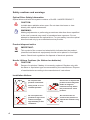
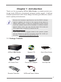
Mini Series User Manual Version 1.0 Published July 2013 Copyright©2013 ASRock INC. All rights reserved. 1 Copyright Notice: No part of this manual may be reproduced, transcribed, transmitted, or translated in any language, in any form or by any means, except duplication of documentation by the purchaser for backup purpose, without written consent of ASRock Inc. Products and corporate names appearing in this manual may or may not be registered trademarks or copyrights of their respective companies, and are used only for identification or explanation and to the owners’ benefit, without intent to infringe. Disclaimer: Specifications and information contained in this manual are furnished for informational use only and subject to change without notice, and should not be constructed as a commitment by ASRock. ASRock assumes no responsibility for any errors or omissions that may appear in this manual. With respect to the contents of this manual, ASRock does not provide warranty of any kind, either expressed or implied, including but not limited to the implied warranties or conditions of merchantability or fitness for a particular purpose. In no event shall ASRock, its directors, officers, employees, or agents be liable for any indirect, special, incidental, or consequential damages (including damages for loss of profits, loss of business, loss of data, interruption of business and the like), even if ASRock has been advised of the possibility of such damages arising from any defect or error in the manual or product. This device complies with Part 15 of the FCC Rules. Operation is subject to the following two conditions: (1) this device may not cause harmful interference, and (2) this device must accept any interference received, including interference that may cause undesired operation. CALIFORNIA, USA ONLY The Lithium battery adopted on this product contains Perchlorate, a toxic substance controlled in Perchlorate Best Management Practices (BMP) regulations passed by the California Legislature. When you discard the Lithium battery in California, USA, please follow the related regulations in advance. “Perchlorate Material-special handling may apply, see www.dtsc.ca.gov/hazardouswaste/perchlorate” ASRock Website: http://www.asrock.com 2 Safety instructions Your system is designed and tested to meet the latest standards of safety for information technology equipment. However, to ensure your safety, it is important that you read the following safety instructions. Setting up your system • Read and follow all instructions in the documentation before you operate your system. • Do not use this product near water or a heated source such as a radiator. • Set up the system on a stable surface. • Openings on the chassis are for ventilation. Do not block or cover these openings. Make sure you leave plenty of space around the system for ventilation. Never insert objects of any kind into the ventilation openings. • Use this product in environments with ambient temperatures between 0o C and 40o C. • If you use an extension cord, make sure that the total ampere rating of the devices plugged into the extension cord does not exceed its ampere rating. Care during use • Do not walk on the power cord or allow anything to rest on it. • Do not spill water or any other liquids on your system. • When the system is turned OFF, a small amount of electrical current still flows. Always unplug all power, modem, and network cables from the power outlets before cleaning the system. • If you encounter the following technical problems with the product, unplug the power cord and contact a qualified service technician or your retailer. • The power cord or plug is damaged. • Liquid has been spilled into the system. • The system does not function properly even if you follow the operating instructions. • The system was dropped or the cabinet is damaged. • The system performance changes. No disassembly NOTE: The warranty does not apply to products (including HDD, ODD, memory and warranty seal) that have been damaged as a result of attempting to disassemble/reassemble the system or modifying the hardware configuration. 3 Safety cautions and warnings Optical Drive Safety Information Optical drives sold with this system contains a CLASS 1 LASER PRODUCT. CAUTION: Invisible laser radiation when open. Do not stare into beam or view directly with optical instruments. WARNING: Making adjustments or performing procedures other than those specified in the user’s manual may result in hazardous laser exposure. Do not attempt to disassemble the optical drive. For your safety, have the optical drive serviced only by an authorized service provider. Product disposal notice IMPORTANT: This symbol of the crossed out wheeled bin indicates that the product (electrical and electronic equipment) should not be placed in municipal waste. Check local regulations for disposal of electronic products. Nordic Lithium Cautions (for lithium-ion batteries) CAUTION! Danger of explosion if battery is incorrectly replaced. Replace only with the same or equivalent type recommended by the manufacturer. Dispose of used batteries according to the manufacturer’s instructions. Installation Notices 4 Do not place this product underneath heavy loads or in an unstable position. Do not use or expose this product around magnetic fields as magnetic interference may affect the performance of the product. Do not expose this product to high levels of direct sunlight, high-humidity or wet conditions. Do not block the air vents to this product or impede the airflow in any way. Contents 1 Introduction........................................................ 7 1.1 1.2 1.3 1.4 1.5 1.6 2 3 4 5 6 7 Package Contents................................................. Specifications........................................................ Motherboard Layout.............................................. Rear Panel............................................................ System Chassis.................................................... Remote Controller................................................. 7 8 10 12 13 14 Quick Installation............................................... Reinstalling the ODD/HDD................................. Installing the Second HDD................................ Dual Monitor....................................................... Driver Installation............................................... Utility Menu......................................................... 15 18 20 22 23 24 7.1 Instant Boot........................................................... 7.1.1 Introduction.................................................. 7.1.2 Installation................................................... 7.2 Symantec Norton AntiVirus Software free bundle (Trial version)........................................................ 7.3 ASRock APP Charger........................................... 7.4 CyberLink MediaEspresso 6.5 (Trial version)....... 7.5 ASRock XFast RAM.............................................. 7.6 ASRock XFast USB............................................... 7.7 ASRock XFast LAN............................................... 7.8 Other Unique Features.......................................... 24 24 25 28 29 30 31 34 37 41 5 8 UEFI SETUP UTILITY.......................................... 43 8.1 Introduction........................................................... 8.1.1 UEFI Menu Bar............................................ 8.1.2 Navigation Keys.......................................... 8.2 Main Screen.......................................................... 8.3 OC Tweaker Screen.............................................. 8.4 Advanced Screen.................................................. 8.4.1 CPU Configuration...................................... 8.4.2 North Bridge Configuration.......................... 8.4.3 South Bridge Configuration......................... 8.4.4 Storage Configuration................................. 8.4.5 Super IO Configuration................................ 8.4.6 ACPI Configuration...................................... 8.4.7 USB Configuration....................................... 8.5 Tool........................................................................ 8.6 Hardware Health Event Monitoring Screen........... 8.7 Boot Screen.......................................................... 8.8 Security Screen..................................................... 8.9 Exit Screen............................................................ 43 43 44 45 46 48 49 50 51 52 53 54 56 57 59 60 62 63 9 Software Support............................................... 64 9.1 Installing an Operating System........................................ 9.2 Support CD Information................................................... 9.2.1 Running Support CD............................................. 9.2.2 Drivers Menu......................................................... 9.2.3 Utilities Menu........................................................ 9.2.4 Contact Information............................................... 6 64 64 64 64 64 64 Chapter 1 Introduction Thank you for purchasing ASRock Mini Series, a reliable product produced under ASRock’s consistently stringent quality control. It delivers excellent performance with robust design conforming to ASRock’s commitment to quality and endurance. Because the hardware specifications and the BIOS software might be updated, the content of this manual will be subject to change without notice. In case any modifications of this manual occur, the updated version will be available on ASRock website without further notice. You may find the latest VGA cards and CPU support lists on ASRock’s website as well. http://www.asrock.com If you require technical support related to this product, please visit our website for specific information about the model you are using. www.asrock.com/support/index.asp 1.1 Package Contents ASRock Mini Series Support CD Quick Start Guide AC Power Cord One AC/DC Adapter Anti-Slip Pad Remote Controller SATA and Power Cables 7 1.2 Specifications * For barebone systems, the HDD, ODD or Memory may not be included. Processor Chipset Memory Display Storage LAN Front I/O Rear I/O Audio ODD WiFi Bluetooth Controller Power Dimension Volume AMD E2-1800 APU AMD A68M Chipset Supports DDR3 1333/1066MHz, 2 x SO-DIMM slots, maximum up to 16GB Integrated AMD Radeon™ HD7340M Graphics Supports up to two 2.5” SATA HDDs and RAID 0/1 Gigabit LAN 2 x USB 3.0, 1 x MIC, 1 x Headphone 1 x HDMI, 1 x DVI-D, 1 x D-Sub VGA, 6 x USB 2.0, 1 x S/PDIF 7.1 Ch HD Audio DVD Super Multi 802.11 b/g/n wireless LAN Bluetooth 4.0/3.0 HS class II MCE Remote Controller 65W/19V Adapter 195mm(W) x 70mm(H) x 186mm(L) 2.5L Free bundle software: 1. Symantec Norton AntiVirus Software (Trial version) 2. CyberLink MediaEspresso 6.5 (trial version) 3. ASRock XFast LAN, XFast RAM, XFast USB 8 WARNING Please realize that there is a certain risk involved with overclocking, including adjusting the setting in the BIOS, applying Untied Overclocking Technology, or using third-party overclocking tools. Overclocking may affect your system’s stability, or even cause damage to the components and devices of your system. It should be done at your own risk and expense. We are not responsible for possible damage caused by overclocking. 9 1.3 Motherboard Layout 12 11 10 9 8 1 2 7 3 4 DDR3_A1 DDR3_A2 5 1. SATA 3.0 connector: For the HDD’s SATA data cable 2. Heatsink 3. Fan connector 4. Fan connector 5. Memory sockets 6. Infrared module header 7. CPU Fan 8. Mini-PCI Express expansion slot: For the WiFi module 9. Clear CMOS jumper 10. SATA 3.0 connector: For the ODD’s SATA data cable 11. ATX5V output power connector for slim ODD & 2.5” HDD 12. SATA 3.0 connector: For the HDD’s SATA data cable 10 6 1. SATA and Power Connections SATA & Power Connections Connect to ODD Connect to HDD Connect to SATA Connector (4) Connect to ATX5V Power Connector (3) Connect to SATA Connector (1) 2. Fan Connection 11 1.4 Rear Panel 24 13 15 23 14 22 21 16 17 20 SON Y HDMI 19 18 DVI D-Sub 13. DC-In jack 14. Optical S/PDIF Out port 15. Mic In (Pink): Microphone 16. Front L/R Out (Lime): Stereo speakers or headphones 17. HDMI connector 18. VGA connector 19. DVI connector 20. USB 2.0 ports: USB devices 21. RJ-45 LAN port: Local Area Network 22. Line In (Blue) for 2/4/6 channel; Rear (Blue) for 8 channel 23. Center/LFE (Orange): Center / Subwoofer speakers 24. Side port for side speakers 12 MP3 1.5 System Chassis 25 26 31 30 29 28 27 25. Optical Disc Drive 26. Power ON/OFF button with status indicator 27. Drive activity indicator 28. Headphone port 29. Microphone port 30. USB 3.0 ports: USB devices 31. Infrared receiver 13 1.6 Remote Controller 14 Some remote controller functions listed above are only available with the relative hardware equipments. If the hardware equipments you adopt are not compatible with the system, you are not allowed to use these functions. This product is designed to meet MCE standards. Chapter 2 Quick Installation 1. Connecting USB Devices to the USB2.0 Ports. 2. Connecting a VGA Monitor to the VGA Port. 3. Connecting the Network with the RJ-45 LAN Port. 4. Connecting an HDMI Device to the HDMI Port. 15 5. Connecting a DVI Device to the DVI Port. 6. Connecting an External Audio Device. (Line In Port for 2/4/6 Channel; Rear Port for 8 Channel) 7. Connecting Stereo Speakers or Headphones. (Front L/R Out Port) 8. Connecting a Microphone. (Mic In Port) 9. Connecting Center / Subwoofer Speakers. (Center/LEF Port) 16 10. Connecting Side Speakers. (Side Port for 4/6/8 Channel) 11. Connecting an Optical Device to the Optical S/PDIF Out Port. 12. Connecting Power to the DC-In Jack. 13. Powering on the System. 14. Connecting Headphones / Microphones / USB3.0 Devices 17 Chapter 3 Reinstalling the ODD/HDD 1. Remove the cover screws on the rear panel. (For safety reasons, please ensure that the power cord is disconnected before opening the case. 2. Slide the side cover toward the rear panel and pull the side cover upwards. 3. To change the storage drives, you need to remove the SATA and power cables from the ODD / HDD first, then unscrew the screws from both sides. 18 4. Pull the ODD / HDD rack backwards and take it out from the bay. 5. Unscrew the screws from the side of the ODD / HDD rack, and change your required ODD / HDD. 6. Refer to the steps above to place the new ODD / HDD to the chassis. Replace the side cover and fasten the screws. 19 Chapter 4 Installing the Second HDD 1. Please follow steps 1 to 4 above, and remove the ODD and the first HDD in advance. Then fasten the screws of the second HDD to the rack. 2. Place the first HDD to the rack and fasten the screws from both sides. 3. Place the ODD to the rack and fasten the screws from both sides. Replace the rack to the chassis. 20 4. Connect the SATA and power cables to the ODD and the bottom HDD. 5. Connect the other SATA and power cables to SATA3_1 and J1 connectors on the motherboard. 6. Connect the other end to the top HDD. 7. Replace the side cover and fasten the screws. 21 Chapter 5 Dual Monitor With the internal VGA output which supports DVI-D, HDMI and D-Sub, you can enjoy dual monitor on your ASRock Mini series HTPC. ASRock Mini series HTPC also provides independent display controllers for DVI-D, HDMI and D-Sub to support dual VGA output so that DVI-D, HDMI and D-Sub can drive the same or different display contents simultaneously. To enable dual monitor, please connect monitor cables to the respective ports on the I/O panel. If you have already installed the VGA driver from our support CD to your system, you can enjoy dual monitor after your system reboots. If you haven’t installed the VGA driver yet, please install the VGA driver from our support CD and restart your computer. HDMI, DVI and D-Sub monitors cannot all be enabled at the same time. You can only choose two of them. 22 Chapter 6 Driver Installation To install the drivers to your system, please insert the support CD to your optical drive first. Then, the drivers compatible to your system can be autodetected and listed on the support CD driver page. Please follow the order from top to bottom to install those required drivers. Therefore, the drivers you install will work properly. 23 Chapter 7 Utility Menu The utility menu shows the applications and other software that this product supports. 7.1 Instant Boot 7.1.1 Introduction Instant Boot, a user-friendly tool that allows you to turn on your PC in just a few seconds, provides a much more efficient way to save energy, time, money, and improves the system’s running speed *. It is applicable to Windows® 8 / 8 64-bit / 7 / 7 64-bit / XP / XP 64-bit. Instant Boot leverages the S3 and S4 ACPI (Advanced Configuration and Power Interface) features which normally enables the Sleep/ Standby and Hibernation modes in Windows® to shorten boot time. By calling S3 and S4 at specific times during the shutdown and startup process, Instant Boot allows you to enter your Windows® desktop in a few seconds. There are two modes of Instant Boot available: Fast Mode and Regular Mode. In Fast Mode, it uses S3 and takes only a few seconds for the OS to resume to working state, which is 10 times faster than the traditional boot time (50 to 60 seconds). Even the Regular Mode is 3 times faster than the traditional boot time. Instant Boot guarantees a clean Windows® boot to consume less power, time and money without any accumulated garbage data, and you can still keep your data safe even when the power is cut off. Also, Windows® update speed will become faster. * This function is applicable ONLY to individuals that do not secure ID and Password to their systems. * The boot time depends on hardware configuration. 24 7.1.2 Installation Please read the procedures below carefully before you install Instant Boot. A. Install Instant Boot driver from ASRock’s support CD, or you may click the following link to get the latest utility and BIOS: http://www.asrock.com/feature/InstantBoot/download.asp B. Execute the Instant Boot installation program under Windows®. Please follow the instructions on Instant Boot’s setup page. a. Click “Next” to continue. b. Select a location. You may choose a different folder if you want to. Then click “Next”. c. Create a start menu folder. You may choose a different folder if you want to. Then click “Next”. 25 d. Click “Install” to begin installing Instant Boot driver. e. Click “Finish” to complete and exit the setup. C. After the installation is completed, you will find an ASRock Instant Boot icon on Windows® desktop. D. Double click ASRock Instant Boot’s icon on the desktop, then Instant Boot’s main menu will pop up. 26 E. On Instant Boot’s main menu, you can choose “Fast Mode”, “Regular Mode” or “Disable Instant Boot”. After that, please click “Apply” to save your changes. Please notice that you need to keep the AC power on if you select “Fast Mode”. F. When you want to shut down the computer, please select “Shut Down” from Windows® “Start menu”. G. The system will restart automatically. After entering into the OS the system will shutdown again. H. Next time when you turn on your system, you can enjoy Instant Boot. 27 7.2 Symantec Norton AntiVirus Software free bundle (Trial version) Protect your PC with Norton Internet Security, the fastest virus, spyware, Internet protection. Norton Internet Security can stop online identity theft, viruses, spyware, bots and more. Stop attacks before they get on your PC, deliver clear threat and performance explanations, identify unsafe web sites right in your search results, and use intelligence-driven Norton Insight Network for faster, fewer, shorter scans. 28 7.3 ASRock APP Charger Fast Charge & Charge Anytime! If you desire a faster, less restricted way of charging your Apple devices, such as an iPhone/iPad/iPod Touch, ASRock has prepared a wonderful solution for you - ASRock App Charger. Simply by installing the App Charger driver makes your iPhone charge much quicker from your computer and up to 40% faster than before. ASRock App Charger allows you to quickly charge many Apple devices simultaneously and even supports continuous charging when your PC enters into Standby mode (S1), Suspend to RAM(S3), hibernation mode (S4) or power off (S5). 29 7.4 CyberLink MediaEspresso 6.5 (Trial version) CyberLink MediaEspresso 6.5 trial now supports Intel® Quick Sync Video hardware transcoding and is optimized for second generation Core i7, i5, and i3 processors to accelerated conversion of all your favorite media files for your favorite portable players. Now you can easily display your favorite movies, songs and photos on iPhone, iPad, PSP, XBox, Youtube, Facebook etc. Compile, convert and enjoy images and songs as much as you want and enhance your videos to new levels with TrueTheater Technology. Try it today! Limitations: 30-day trial limitation Convert videos to the H.264 format 50 times 30 7.5 XFast RAM ASRock XFast RAM is a new function that is included in ASRock Extreme Tuning Utility (AXTU). It fully utilizes the memory space that cannot be used under Windows® 32-bit OS. ASRock XFast RAM shortens the loading time of previously visited websites, making web surfing faster than ever. And it also boosts the speed of Adobe Photoshop 5 times faster. Another advantage of ASRock XFast RAM is that it reduces the frequency of accessing your SSDs or HDDs in order to extend their lifespan. 31 XFast RAM Settings You may find the XFast RAM setup page in the left panel of ASRock Extreme Tuning utility. First select the desired drive and disk size to create a virtual drive. To access more than 4GB of RAM in Windows® 32-bit OS, please leave PAE mode set to ON. In the options section, users may enable and assign the size of a partition for Ready Boost if they’re using a 32-bit OS. We suggest setting the size of Ready Boost one to three times larger than your RAM for optimized performance. Normally, when the memory being used by all the existing processes exceeds the available RAM, the operating system moves pages (4-KB pieces) of one or more virtual address spaces to the computer’s hard disk. By enabling Memory Pagefile, the system puts the pages into the virtual 32 drive instead of the hard disk drive to accelerate performance speed. Lastly, select the files that are supposed to go in the virtual drive to speed up the system’s performance. Such as temporary files created by computer programs when they cannot allocate enough memory for its tasks. Or internet cache files including html, images, Cascading Style Sheets and JavaScript scripts from IE, Firefox and Google Chrome. Click Backup XFast RAM if you wish to make a backup. Then click on the APPLY button to activate XFast RAM. Click on STOP if you wish to deactivate XFastRAM. The virtual disk will appear once you restart the system. 33 7.6 ASRock XFast USB Not only does ASRock XFast USB boost up the performance of USB 2.0 storage devices, but also USB 3.0 devices. Users may experience up to five times faster USB data transfer speed! 34 XFast USB UI overview Hide the XFast USB window Select your language Select a connected USB storage device Click to activate/ deactivate Turbo mode Select Normal mode or Turbo mode Click to safely remove the USB hard drive Plug in your USB storage device and XFast USB automatically sets it to Turbo mode! 35 D. Then, you will see ASRock XFast USB user interface as below. You can also double-click the “XFast USB” icon to show this interface. Please choose “Turbo” to enable ASRock XFast USB Technology. The detailed information of your USB device can also be found in this user interface. 36 7.7 ASRock XFast LAN ASRock XFast LAN provides several special features for faster internet access. For example, LAN Application Prioritization allows you to configure your application’s priority ideally or add new programs to the priority list. Traffic Shaping helps you watch Youtube HD videos and download files simultaneously without hiccups. And in the status window there’s RealTime Analysis of Your Data so you can easily recognize the data streams you are transferring currently. 37 XFast LAN UI overview The default status window Low Latency Mode switch arrow down = currently Open slot on (if needed) configuration arrow up = always on Download activity display dialog no arrow = off Open Current Connections window TX shaping indicator Ping time in ms Show/hide slot activation area Number of TCP/ UDP/TCP+UDP connections Variance of ping time Download CPS rate Graphs Transfer rate in % for slots 1-10 Upload CPS rate Upload activity display Right click for more options Close Windows Hides the status window. Can also be done by double clicking on the status window. Reopen by right clicking on the XFast LAN icon on the 38 bottom right and selecting Open windows. Window settings Users may configure the skin and effects of the user interface. Make the keyboard LEDs display Traffic Shaping information. Or display the XFast LAN status window on a Logitech gamer keyboard instead of Windows desktop. Traffic Shaping Traffic Shaping is used to optimize or guarantee performance, improve latency, and/or increase usable bandwidth for some kinds of packets by delaying other kinds of packets that meet certain criteria. In other words, it increases the speed while keeping the overall ping time low. cFos Speed Test Quickly test the upload and download speed of your Internet connection. Speed Guide This guide can either help you get the maximum out of your connection or solve problems with speed, ping time or connections. Current Connection Shows the details of current internet connections. Usage Graph Displays the Usage Graph. Options Configure settings such as program prioritization, language and update the program. Documentation Opens detailed help for XFast LAN in a browser. 39 Adding a new application and changing its priority Click search and choose a new program you wish to add. You can also type in a short description for the program. Set the priority for the program and TX Limit then click Add to confirm. Hit the switch button to change configurations or Delete to remove the application from the priority list. 40 7.8 Other Unique Features ASRock Instant Flash ASRock Instant Flash is a BIOS flash utility embedded in Flash ROM. This convenient BIOS update tool allows you to update system BIOS without entering operating systems first like MS-DOS or Windows®. With this utility, you can press the <F6> key during the POST or the <F2> key to enter into the BIOS setup menu to access ASRock Instant Flash. Just launch this tool and save the new BIOS file to your USB flash drive, floppy disk or hard drive, then you can update your BIOS only in a few clicks without preparing an additional floppy diskette or other complicated flash utility. Please be noted that the USB flash drive or hard drive must use FAT32/16/12 file system. ASRock OMG (Online Management Guard) Administrators are able to establish an internet curfew or restrict internet access at specified times via OMG. You may schedule the starting and ending hours of internet access granted to other users. In order to prevent users from bypassing OMG, guest accounts without permission to modify the system time are required. ASRock Internet Flash ASRock Internet Flash searches for available UEFI firmware updates from our servers. In other words, the system can auto-detect the latest UEFI from our servers and flash them without entering Windows® OS. Please note that you must be running on a DHCP configured computer in order to enable this function. ASRock Dehumidifier Function Users may prevent motherboard damages due to dampness by enabling “Dehumidifier Function”. When enabling Dehumidifier Function, the computer will power on 41 automatically to dehumidify the system after entering S4/ S5 state. ASRock Fast Boot With ASRock’s exclusive Fast Boot technology, it takes less than 1.5 seconds to logon to Windows 8 from a cold boot. No more waiting! The speedy boot will completely change your user experience and behavior. ASRock Restart to UEFI Windows ® 8 brings the ultimate boot up experience. The lightning boot up speed makes it hard to access the UEFI setup. ASRock Restart to UEFI allows users to easily enter the UEFI automatically when turning on the PC. Just simply enable this function; the PC will enter the UEFI directly after you restart. ASRock Good Night LED ASRock Good Night LED technology can offer you a better environment by extinguishing the unessential LED. By enabling Good Night LED in BIOS, the Power / HDD / LAN LED will be switched off when system is on. Not only this, Good night LED will automatically switch off Power and Keyboard LED when the system enters into Standby / Hibernation mode as well. 42 Chapter 8: UEFI SETUP UTILITY 8.1 Introduction This section explains how to use the UEFI SETUP UTILITY to configure your system. The UEFI chip on the motherboard stores the UEFI SETUP UTILITY. You may run the UEFI SETUP UTILITY when you start up the computer. Please press <F2> or <Del> during the Power-On-Self-Test (POST) to enter the UEFI SETUP UTILITY, otherawise, POST will continue with its test routines. If you wish to enter the UEFI SETUP UTILITY after POST, restart the system by pressing <Ctl> + <Alt> + <Delete>, or by pressing the reset button on the system chassis. You may also restart by turning the system off and then back on. Because the UEFI software is constantly being updated, the following UEFI setup screens and descriptions are for reference purpose only, and they may not exactly match what you see on your screen. 8.1.1 UEFI Menu Bar The top of the screen has a menu bar with the following selections: Main For setting system time/date information OC Tweaker For overclocking configurations Advanced For advanced system configurations Tool Useful tools H/W Monitor Displays current hardware status Boot For configuring boot settings and boot priority Security For security settings Exit Exit the current screen or the UEFI Setup Utility 43 8.1.2 Navigation Keys Use < > key or < > key to choose among the selections on the menu bar, and use < > key or < > key to move the cursor up or down to select items, then press <Enter> to get into the sub screen. You can also use the mouse to click your required item. Please check the following table for the descriptions of each navigation key. Navigation Key(s) + / <Tab> <PGUP> <PGDN> <HOME> <END> <F1> <F7> <F9> <F10> <F12> <ESC> 44 Description To change option for the selected items Switch to next function Go to the previous page Go to the next page Go to the top of the screen Go to the bottom of the screen To display the General Help Screen Discard changes and exit the SETUP UTILITY Load optimal default values for all the settings Save changes and exit the SETUP UTILITY Print screen Jump to the Exit Screen or exit the current screen 8.2 Main Screen When you enter the UEFI SETUP UTILITY, the Main screen will appear and display the system overview. 45 8.3 OC Tweaker Screen In the OC Tweaker screen, you can set up overclocking features. DRAM Timing Configuration DRAM Frequency If [Auto] is selected, the motherboard will detect the memory module(s) inserted and assigns appropriate frequency automatically. Power Down Mode Use this to enable or disable DDR power down mode. Bank Interleaving Interleaving allows memory accesses to be spread out over banks on the same node, or accross nodes, decreasing access contention. DRAM tCL 46 Use this to change CAS# Latency (tCL) Auto/Manual settings. The default is [Auto]. DRAM tRCD Use this to change RAS# to CAS# Delay (tRCD) Auto/Manual settings. The default is [Auto]. DRAM tRP Use this to change Row Precharge Time (tRP) Auto/Manual settings. The default is [Auto]. DRAM tRAS Use this to change RAS# Active Time (tRAS) Auto/Manual settings. The default is [Auto]. Command Rate (CR) Use this to change Command Rate (CR) Auto/Manual settings. The default is [Auto]. RAS# Cycle Time (tRC) Use this to change RAS# Cycle Time (tRC) Auto/Manual settings. The default is [Auto]. DRAM tWR Use this to change Write Recovery Time (tWR) Auto/Manual settings. The default is [Auto]. DRAM tRFC Use this to change Refresh Cyle Time (tRFC) Auto/Manual settings. The default is [Auto]. DRAM tRRD Use this to change RAS to RAS Delay (tRRD) Auto/Manual settings. The default is [Auto]. DRAM tWTR Use this to change Write to Read Delay (tWTR) Auto/Manual settings. The default is [Auto]. DRAM tRTP Use this to change Read to Precharge (tRTP) Auto/Manual settings. The default is [Auto]. DRAM tFAW Use this to change Four Activate Window (tFAW) Auto/Manual settings. The default is [Auto]. 47 8.4 Advanced Screen In this section, you may set the configurations for the following items: CPU Configuration, Nouth Bridge Configuration, South Bridge Configuration, Storage Configuration, Super IO Configuration, ACPI Configuration and USB Configuration. Setting wrong values in this section may cause the system to malfunction. 48 8.4.1 CPU Configuration Cool ‘n’ Quiet Use this to enable or disable AMD’s Cool ‘n’ QuietTM technology. The default value is [Enabled]. Configuration options: [Enabled] and [Disabled]. If you install Windows® 7 / VistaTM and want to enable this function, please set this to [Enabled]. Please note that enabling this may reduce CPU voltage and memory frequency, and lead to system stability or compatibility issues with some memory modules or power supplies. Please set this to [Disabled] if these issues occur. SVM When this is set to [Enabled], a VMM (Virtual Machine Architecture) can utilize the additional hardware capabilities provided by AMD-V. The default value is [Enabled]. Configuration options: [Enabled] and [Disabled]. C6 Mode Use this to enable C6 Mode. The default value is [Disabled]. 49 8.4.2 North Bridge Configuration Share Memory This allows you to configure share memory. The default value is [Auto]. Onboard HDMI HD Audio This allows you to enable or disable the Onboard HDMI HD Audio. 50 8.4.3 South Bridge Configuration Onboard HD Audio Select [Auto], [Enabled] or [Disabled] for the onboard HD Audio. If you select [Auto], the onboard HD Audio will be disabled when a PCI Sound Card is plugged. On/Off Play Use this to enable or disable On/Off Play Technology. The default value is [Enabled]. When On/Off Play is enabled, Deep Sleep will be disabled. If you want to enable Deep Sleep, please disable On/ Off Play first. Onboard LAN This allows you to enable or disable the Onboard LAN. Deep S5 Mobile platforms support Deep S4/S5 in DC only and desktop platforms support Deep S4/S5 in AC only. Restore on AC/Power Loss This allows you to set the power state after an unexpected AC/ power loss. If [Power Off] is selected, the AC/power remains off when the power recovers. If [Power On] is selected, the AC/power resumes and the system starts to boot up when the power recovers. Good Night LED Use this to enable or disable the Power LED and LAN LED. 51 8.4.4 Storage Configuration SATA Controller Use this to enable or disable the SATA Controller. SATA Mode Use this to select the SATA mode for SATA3_1 port. Configuration options: [IDE Mode] and [AHCI Mode]. The default value is [AHCI Mode]. AHCI (Advanced Host Controller Interface) supports NCQ and other new features that will improve SATA disk performance but IDE mode does not have these advantages. SATA Aggressive Link Power Management Use this to configure Aggressive Link Power Management. Hard Disk S.M.A.R.T. Use this to enable or disable S.M.A.R.T. (Self-Monitoring, Analysis, and Reporting Technology). Marvell SATA3 Operation Mode Use this to select the SATA mode for SATA3_M0 and SATA3_M1 ports. Configuration options: [IDE Mode], [AHCI Mode] and [RAID Mode]. The default value is [RAID Mode]. 52 8.4.5 Super IO Configuration Infrared Port Use this to enable or disable the onboard infrared port. CIR Controller Use this to enable or disable the CIR Controller. 53 8.4.6 ACPI Configuration Suspend to RAM Use this to select whether to auto-detect or disable Suspend-toRAM. Select [Auto] to enable if the OS supports it. Check Ready Bit Use this to enable or disable Check Ready Bit. ACPI HPET Table Use this to enable or disable the ACPI HPET Table. The default value is [Enabled]. Please set this option to [Enabled] if you plan to use this motherboard to submit Windows® VistaTM certification. Onboard LAN Power On Use this to enable or disable the Onboard LAN to power on the system. CIR Power On Use this to enable or disable the CIR to power on the system. RTC Alarm Power On Use this to enable or disable the RTC (Real Time Clock) to power on the system. USB Keyboard/Remote Power On Use this to enable or disable the USB Keyboard/Remote to power on the system. USB Mouse Power On Use this to enable or disable the USB Mouse to power on the system. 54 CSM Please disable CSM when Fast Boot is enabled. The default value is [Enabled]. 55 8.4.7 USB Configuration Legacy USB Support Use this to select legacy support for USB devices. There are four configuration options: [Enabled], [Auto], [Disabled] and [UEFI Setup Only]. The default value is [Enabled]. Please refer to the descriptions below for details of these four options: [Enabled] - Enables support for legacy USB. [Auto] - Enables legacy support if USB devices are connected. [Disabled] - USB devices are not allowed to be used under legacy OS and UEFI setup when [Disabled] is selected. If you have USB compatibility issues, it is recommended to select [Disabled] to enter the OS. [UEFI Setup Only] - USB devices are allowed to be used only under UEFI setup and Windows / Linux OS. Legacy USB 3.0 Support Use this to enable or disable legacy support for USB 3.0 devices. The default value is [Enabled]. 56 8.5 Tool OMG (Online Management Guard) Administrators are able to establish an internet curfew or restrict internet access at specified times via OMG. You may schedule the starting and ending hours of internet access granted to other users. In order to prevent users from bypassing OMG, guest accounts without permission to modify the system time are required. Instant Flash Instant Flash is a UEFI flash utility embedded in Flash ROM. This convenient UEFI update tool allows you to update the system UEFI without entering operating systems like MS-DOS or Windows® first. Just save the new UEFI file to your USB flash drive, floppy disk or hard drive and launch this tool, then you can update your UEFI only in a few clicks without preparing an additional floppy diskette or other complicated flash utility. Please be noted that the USB flash drive or hard drive must use FAT32/16/12 file system. If you execute Instant Flash utility, the utility will show the UEFI files and their respective information. Select the proper UEFI file to update your UEFI, and reboot your system after the UEFI update process is completed. Internet Flash Internet Flash searches for available UEFI firmware updates from our servers. In other words, the system can auto-detect the latest UEFI from our servers and flash them without entering Windows 57 OS. Please note that you must be running on a DHCP configured computer in order to enable this function. Network Configuration Use this to configure internet connection settings for Internet Flash. User Defaults You are allowed to load and save three user defaults according to your own requirements. 58 8.6 Hardware Health Event Monitoring Screen This section allows you to monitor the status of the hardware on your system, including the parameters of the CPU temperature, motherboard temperature, fan speed and voltage. CPU Fan 1 Setting This allows you to set CPU fan 1’s speed. The default value is [Automatic Mode]. CHA Fan 1 Setting This allows you to set chassis fan 1’s speed. The default value is [Automatic Mode]. 59 8.7 Boot Screen This section displays the available devices on your system for you to configure the boot settings and the boot priority. Fast Boot Fast Boot minimizes your computer’s boot time. Configuration options: [Disabled] - Disable Fast Boot. [Fast]: When selecting “Fast”, it is not allowed to boot from a USB storage device. [Ultra Fast]: There are a few restrictions 1. Only supports Windows 8 UEFI operating system 2. You will not be able to enter BIOS Setup by using the keyboard. The only way to enter UEFI Setup is to clear CMOS or run the “Restart to UEFI” utility in windows. 3. If you are using an external graphics card, the VBIOS must support UEFI GOP in order to boot. Boot From Onboard LAN Use this to enable or disable Boot From Onboard LAN. Setup Prompt Timeout This shows the number of seconds to wait for the setup activation key. 65535(0xFFFF) means indefinite waiting. Bootup Num-Lock If this is set to [On], it will automatically activate the Numeric Lock 60 after boot-up. Full Screen Logo Use this item to enable or disable OEM Logo. The default value is [Enabled]. AddOn ROM Display Use this option to adjust AddOn ROM Display. If you enable the option “Full Screen Logo” but you want to see the AddOn ROM information when the system boots, please select [Enabled]. Configuration options: [Enabled] and [Disabled]. The default value is [Enabled]. Boot Failure Guard Enable or disable Boot Failure Guard. Boot Failure Guard Count Enable or disable Boot Failure Guard Count. 61 8.8 Security Screen In this section you may set or change the supervisor/user password for the system. You may also clear the user password. Secure Boot Use this to enable or disable Secure Boot Control. The default value is [Disabled]. 62 8.9 Exit Screen Save Changes and Exit When you select this option the following message, “Save configuration changes and exit setup?” will pop out. Select [OK] to save changes and exit the UEFI SETUP UTILITY. Discard Changes and Exit When you select this option the following message, “Discard changes and exit setup?” will pop out. Select [OK] to exit the UEFI SETUP UTILITY without saving any changes. Discard Changes When you select this option the following message, “Discard changes?” will pop out. Select [OK] to discard all changes. Load UEFI Defaults Load UEFI default values for all options. The F9 key can be used for this operation. 63 Chapter 9 Software Support 9.1 Installing an Operating System This system supports various Microsoft® Windows® operating systems: 8 / 8 64-bit / 7 / 7 64-bit / XP / XP 64-bit. Refer to your OS documentation for more information. 9.2 Support CD Information The Support CD contains necessary drivers and useful utilities that enhance the system features. 9.2.1 Running The Support CD To begin using the support CD, insert the CD into your CD-ROM drive. The CD automatically displays the Main Menu if “AUTORUN” is enabled in your computer. If the Main Menu does not appear automatically, locate and double click on the file “ASRSETUP.EXE” in the Support CD to display the menu. 9.2.2 Drivers Menu The Drivers Menu shows the available devices drivers if the system detects installed devices. Please install the necessary drivers to activate the devices. 9.2.3 Utilities Menu The Utilities Menu shows the applications software that the system supports. Click on a specific item then follow the installation wizard to install it. 9.2.4 Contact Information If you need to contact ASRock or want to know more about ASRock, you are welcome to visit ASRock’s website at http://www.asrock.com; or you may contact your dealer for further information. 64