1
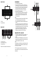
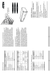
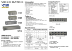
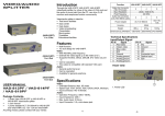
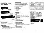
Introduction
VIDEO MATRIX
Through the video matrix, you can use 2 PCs to display
the diverse images on 2 or 4 monitors; meanwhile, optional means for controlling monitor´s image either come
from PC „A“ or PC „B“ or just switching off.
Video matrix is ideal for:
2 in 2 Out
(DS-47110-1)
• Test bench facilities
• Data center
• Help desks
• Video broadcasting:
Presentation
Stock quotes
Timetables
Educational facilities
Specifications
Function
2 port
4 port
Video Input Connector
(HD-15 Female)
2
2
Video Output Connector
(HD-15 Female)
2
4
Select Switch
2
4
A (Green)
2
4
B (Red)
2
4
Linked LEDs
1920 x 1440 60 Hz
Pixel Frequency
250 MHz
Cable Distance
(Device to Monitor)
65 m (213´´) Max.
Signal Type
VGA, SVGA, XGA, Multisync
Power Adapter (Min.)
DC12V 1A
Housing
Weight
Metal
420 g
Dimensions (LxWxH)
Features
2 in 4 Out
(DS-48110-1)
Max. Resolution
• Intelligent functionality.
• With 250 MHz pixel frequency.
• Extends the video signal up to 65 meter (213´´).
• Supports the DDC, DDC2, DDC2B. (For video out port
1 and 2)
• Can be cascaded.
• The output is compatible with standard VGA card.
• Free select from PC (A) or PC (B) or switch off by
means of the front panel switch.
USER MANUAL
Package Contens
• 1 video matrix
• 1 user manual
• 1 DC12V 1A power adapter
Any thing missed, please contact with your vendor.
Technical Specifications
Input/Output Signal
Pin#
Signal
Pin#
Signal
1
Red video
9
NC
2
Green video
10
Ground
3
Blue video
11
ID0 *
4
ID2 *
12
ID1 *
5
Ground
13
Horizontal sync
6
Analog ground
14
Vertical sync
7
Analog ground
15
ID3 *
8
Analog ground
* For video out port 1 and 2.
-1-
455 g
130 x 75 x 42 mm
-2-
Installation
FRONT VIEW
1. Turn off the PCs and monitors.
2. Connect the HD-15 video extension cable between the VGA card of PCs and the „video in“ port of matrix.
3.Connect the HD-15 video extension cables between the monitors and the „video out“ port of matrix.
4.Connect the power cord and turn on the matrix.
5.Turn on the PCs and monitors.
6.Control front panal switch to obtain the image either come from PC (A) [Linked LED „(A)“ on] or PC (B) [Linked LED “(B)” on] or just switching off. [Linked LED “(A) (B)” off]
Note:
• All the “video out” ports will connect with the “video in” port of (A) while turning on the video matrix.
• If you install the DDC monitor for the splitter, the rest of moni
tors must be the same resolution as the DDC monitor.
• The functionality of DDC comes from „video in“ port of (A) connecting with „video out“ port 1 as well as „video in“ port of (B) connecting with „video out“ port 2.
• Available monitors include the VGA, SVGA, XGA, Mulitsync, and exclude the CGA, EGA, Mono.
(1)
(2)
1. Select
2. (A), (B) Linked
REAR VIEW
Operation for cascade:
(1)
(2)
(3)
1. Input Power Jack.
2. (A), (B) „Video In“ Port
3. „Video Out“ Port
There are 2/4 out ports for the video matrix
1.The function to display image on more monitors, you
request to attach video matrix or standard video
splitter.
2.Connect the HD-15 Male/Male video extension cable
between the former matrix of the „video out“ port and the latter matrix of the „video in“ port.
Note:
Even though you are allowed to cascade the matrix with
varied ports, the image might become unstable if cascade too many tiers of matrix.
P.S.: The example cascades the 2 and 4 port video
matrix; however, you can cascade the video matrix with
desired port.
-3-
-4-