1
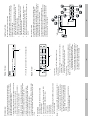
Red video Green video Blue video ID2 Ground Analog Ground Analog Ground Analog Ground 2 3 4 5 6 7 8 Assignment 1 No. -4- 15 14 13 12 11 10 9 No. 530 g 200 MHz 1792 x 1344 @ 60 Hz 8 3.42 W 130 x 185 x 57 mm 450 g 320 g 130 x 75 x 20 mm 250 MHz 250 MHz 1920 x 1440 @ 60 Hz 4 2 ID3 Vertical Sync Horizontal Sync ID1 ID0 Ground NC Assignment Video Out Pin Assignments Dimensions (L x W x H) Weight Bandwidth (-3db) Max. Resolution Video Output Connectors (HDB-15 Female) DC 9VPower Consumption (Max.) 1.62W Housing 0.85 W Metal Humidity VS-98A 0 - 80% RH, Non-condensing Storage Temperature VS-94A -20 - 60o C Operating Temperature VS-92A 5 - 40o C Video Input Connectors Function VGA, SVGA, XGA, Multisync 1 x HDB-15 Male Signal Type 65 m (213’) max. Specification Cable Distance (Device to Monitor) Function Specifications -5- The direct vendor makes no warranty or representation, expressed, implied, or statutory with respect to the contents or use of this documentation, and especially disclaims its quality, performance, merchantability, or fitness for any particular purpose. The direct vendor also reserves the right to revise or update the device or documentation without obligation to notify any individual or entity of such revisions, or update. For further inquiries, please contact your direct vendor. IN NO EVENT SHALL THE DIRECT VENDOR’S LIABILITY FOR DIRECT, INDIRECT, SPECIAL, INCIDENTAL, OR CONSEQUENTIAL DAMAGES RESULTING FROM THE USE OF THE PRODUCT, DISK, OR ITS DOCUMENTATION EXCEED THE PRICE PAID FOR THE PRODUCT. Limited Warranty WARNING!!! This equipment generates, uses and can radiate radio frequency energy and, if not installed and used in accordance with the instruction manual, may cause interference to radio communications. This equipment has been tested and found to comply with the limits for a Class A computing device pursuant to Subpart J of Part 15 of the FCC Rules, which are designed to provide reasonable protection against such interference when operated in a commercial environment. Operation of this equipment in a residential area is likely to cause interference, in which case the user, at his own expense, will be required to take whatever measures may be required to correct the interference. Radio & TV Interference All brand names and trademarks are the registered property of their respective owners. © Copyright 2000 ATEN International Co., Ltd. Manual Part No. PAPE-1183-200 Printed in Taiwan 12/2000 If anything is damaged or missing, contact your dealer. M 1 User Manual M 1 DC 9V Power Adapter M 1 VS-92A or VS-94A or VS-98A Video Splitter This package contains: Read this manual thoroughly and follow the installation and operation procedures carefully to prevent any damage to the unit, and/or any of the devices connected to it. VS-92A / VS-94A / VS-98A User Manual 1 In 8 Out 1 In 4 Out 1 In 2 Out -1- 3. For the best video quality, we recommend using UL2919 rated extender cables. 2. These products are designed for VGA, SVGA, and Mulitsync monitors. They are not suitable for CGA, EGA, or MONO type monitors that use digital video signals. Note: 1. If you connect a DDC type monitor to Video Out Port 1, all other monitors must be able to support the highest resolution that the DDC monitor can provide. M Ideal for Public Broadcasting; Remote Monitoring; Classroom and Training Facilities M Small Form Factor M All Metal Housing M Daisy Chainable M Supports DDC, DDC2, DDC2B (Port 1 Only) M Enhances Video Signal for Distances up to 65 m (213’) M Ultra High 250 MHz (VS-92A / VS-94A) or 200 MHz (VS-98A) Bandwidth Features 3 -2- 2. The Front and Rear Views in the diagrams are for a VS-98A. A VS-92A and VS-94A will have two and four Video Out Ports, respectively, instead of the eight Video Out Ports shown in the diagram. Note: 1. If you connect a DDC type monitor to Video Out Port 1, all other monitors must be able to support the highest resolution that the DDC monitor can provide. M If this is a Daisy Chained unit, the cable from the Video Out port of the higher stage unit plugs in here. 3. Video Out Ports The cables to the monitors can plug in to any available port. M If this is a First Stage unit, the cable from the PC’s video port plugs in here. 1. Power Jack The cable from the Power Adapter plugs in here. 2. Video In Port 2 1 Rear View To achieve multiple high quality VGA, SVGA, or Multisync video signals over long distances, these video splitters are your best choice. 1 1. Power LED Lights to indicate the unit is receiving power. Front View In addition, units can be daisy chained to handle as many monitors as the installation requires, making them excellent solutions for public broadcast systems. The VS-92A, VS-94A, and VS-98A go beyond being merely duplicators, however, in that they also enhance the video signals over long distance broadcasting of up to 65 m (213’). 3) Classroom or company training facilities 2) Monitoring harsh work environments from safe locations 1) Broadcasting video information (news headlines, stock prices, airline and train schedules, etc.), to the public These video splitters are boosting devices that duplicate the video signal from any anolog monitor source to two (VS-92A); four (VS-94A); or eight (VS-98A) outputs. As such, they provide fast, flexible, solutions for situations such as: Overview -3- You can chain as many Video Splitters as there are ports available, and all three models can be mixed on the same chain. Theoretically, there is no limit to the number of splitters that can be chained, but the quality will deteriorate as you chain further and further away from the video signal. To provide video display for more monitors, additional Video Splitters can be daisy chained. Use a high density HDB-15 male/female video extender cable (Part No. 2L-2401), to connect any available Video Out port on the higher level Video Splitter to the Video In port of the lower level Video Splitter. Daisy Chaining In a Single Stage installation no additional Video Splitters are daisy chained down from the first unit. To set up a single stage installation do the following: 1. Use a high density HDB-15 male/female video extender cable (Part No. 2L-2401) to connect the PC’s video port to the Video In port of the Video Splitter. 2. Use high density HDB-15 male/female video extender cables (Part No. 2L-2401) to connect the Video Out ports of the Video Splitter to the monitors. 3. Plug the power adapter into an AC source; plug the power adapter cable into the Video Splitter’s Power Jack. 4. Power up the Video Splitter; power up the monitors; power up the PC. Single Stage Installation Installation