1
3 • Receiver Installation
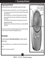
1.Use the 2 large (orange) wire connectors supplied to connect the receiver and Figure 6
house wiring, then use the 3 small (blue) wire connectors supplied to connect
the receiver and ceiling fan wiring. Refer to the Wiring Diagram in Figure 6.
If you are installing the remote with a Hunter Fan, the wire colors in the fan
will be as follows:
Light Power = Black with a White Stripe
Fan Power = Black
Common = White
*These are only the Hunter fan wire colors. Other brands may use different colors.
Antenna
AC
Power
In
2.Be sure the antenna is positioned securely, so it does not interfere with the
ceiling fan motor. Do not modify or damage the antenna wire, as control
performance may be reduced. After securing the receiver, antenna, and
wiring, finish hanging the ceiling fan according to its instructions.
Black/Hot (marked “LIVE
IN” on red label)
White/Neutral (marked
“NEUTRAL IN” on red
label)
White (marked
“COMMON OUT” on
white label)
3.Restore power at main electrical panel.
Red
(“LIGHT
OUT”)
Black
(“FAN
OUT”)
Black
White* Black* &
White*
Common Fan
Light
Wiring Diagram
*Hunter fan wire colors. Other brands may use different colors.
6
44092-01 • 12/15/10 • Hunter Fan Company