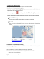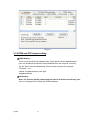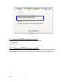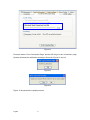
1
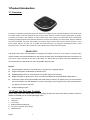
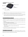
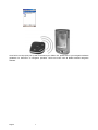
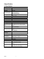
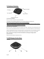
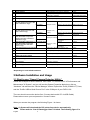
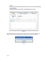
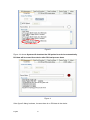
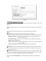
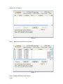
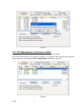
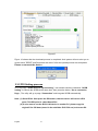
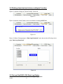
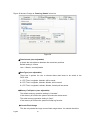
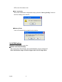
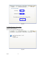
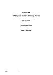
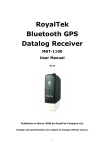
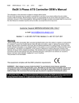
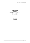
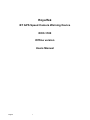
RoyalTek
BT GPS Speed Camera Warning Device
RCD-1100
Offline version
Users Manual
English
1
Content
1.Product Introduction .........................................................................................................................3
1.1 Overview................................................................................................................................3
1.2 Check the Package Content....................................................................................................3
1.3 Install RCD-1100 in your vehicle ..........................................................................................4
1.4 Product Notification- Using Tips ...........................................................................................4
1.5 Navigation Function via BT...................................................................................................4
2.Specification......................................................................................................................................6
2.1 Specification...........................................................................................................................6
2.2 Hardware Overview ...............................................................................................................7
2.3 LED Display & Audio Alarm ................................................................................................7
3.Software Installation and Usage .......................................................................................................8
3.1 Start to use “Speed Camera Detector Utility”........................................................................8
3.2 POI Management Procedure ................................................................................................ 11
3.3 SCDB and POI import setting..............................................................................................15
3.4 Datalog download and device configure Function ..............................................................19
3.5 Get and Set RCD-1100 Data Log Status..............................................................................19
3.6 SCDB Setting.......................................................................................................................21
3.7 Utility Revision information ................................................................................................22
English
2
1.Product Introduction
1.1 Overview
The Device is equipped with the latest generation SiRF Star III digital processor specially designed for fast and accurate
fix on GPS signals. It had been designed to help you drive safety within the confines of today’s speed limits, by alerting
you quickly and easily to the presence of Police speed traps, often located at Accident black spots, electronically
indicating potentially dangerous and hazardous situations. The RCD-1100 will help you to drive safely, when the database
has been downloaded, the device will compare your position using its built-in GPS antenna with the position of every
known danger locations and give you an audible and visual warning as you approach them.With the latest in GPS
technology, RCD-1100 device also can become a BT GPS Receiver to deliver GPS information.
- READ FIRST The RCD-1100 comes with a database of cameras pre-loaded. However the road network is constantly being
modified. Please note that the database on the device will have been downloaded at the time of production so
may not be 100% accurate at the time of purchase. To ensure that your RCD-1100 works affectively we
recommend that you download it as soon as possible after purchase.
Feature:
z
Easy installation and put on the dashboard, just plug into the cigarette lighter.
z
Support Navigation via Bluetooth for Mobile phone.
z
Update database via mini USB connector on PC/NB. (Internet Connection)
z
Bright LED lights for Speed Limit, GPS, POI status and Bluetooth, and adjustable audible alarms.
z
Automatic system warning with audible and visual alerts to reduce your speed. Know your exact position
and current speed, use the database to continue checking if you are approaching a risk area and warns
you before you enter a risk area.
z
Support datalog function
1.2 Check the Package Content
Before using RCD-1100, please make sure the package includes the items listed below. Please contact the
reseller immediately for any missing/damaged items.
1.
RCD-1100 Device
2.
USB cable
3.
Car Charger
4. External antenna (optional)
5. CD (user manual, SW utility)
6.
Dashboard Pad
English
3
1.3 Install RCD-1100 in your vehicle
(D) Speed Limit button
(E) POI Button
(C) Volume Control
(A) Mini USB Port
(B) External Antenna Port
z
Place the Dashboard Pad on your dashboard as close to the windscreen as possible in clear view of the driver’s line
of sight.
z
Place your RCD-1100 device on the dashboard pad, which is designed to hold it firmly in place.
z
Now connect the USB cable to the cigar lighter adapter provided and insert the other end to socket (A). Plug the
adapter into the vehicle’s cigar lighter. RCD-1100 powers on once you turn your ignition key and the green and red
LEDs will sweep backwards and forwards with one beep tells you that the unit is functioning correctly.
1.4 Product Notification- Using Tips
1. Use the supplied dashboard pad, remove the backing from the base, fix it on the dashboard as close to
the windscreen as possible in clear view of the driver’s line of the sight and place your Detector onto the
pad
2. Cars that are equipped with heat dissipation films for the windshield and windows will degrade the GPS
performance.
3. For the most accurate position fix results and quickest acquisition time, please make sure that your device
is not in motion but stationary and in open spaces.
4. Connect to PC or Notebook for “Speed Camera Detector Utility”
@User can update the Camera database and manage the POI points using the supplied “Speed Camera
Detector Utility”.
Refer to the software installation and usage to install the software utility.
*POI: point of interest
5. We invite the driver to respect the driving rule and the law. We assume no any responsibility for any
damage or injury resulting from the wrong use of the product.
1.5 Navigation Function via BT
To make RCD-1100 Receiver work with your devices, a simple pairing step is required for the first time.
(Please follow the pairing instruction for Blue Tooth from your PDA or PC manufacturer.) To get RCD-1100 into
pairing mode, all you need to do is simply switch on the power switch.
English
4
Once RCD-1100 is properly set up and connected to your PDA or PC, please refer to your navigation software
guidebook for instruction on navigation operation. RCD-1100 works with all NMEA enabled navigation
software.
English
5
2.Specification
2.1 Specification
GPS
GPS Chipset
Frequency
Channel
C/A Code
Chipset TTFF
(Open SKY,typical)
Accuracy
- Sirf star III
- L1, 1,575.42 MHz
- 20 parallel
- 1,023 MHz
- Reacquisition: less than 1s
- Hot start: less than 1s
- Warm start: less than 35s
- Cold start: less than 35s
- Position: within 10m for 90%
- Velocity: 0.1m/s
Dynamics
- 18,000 meter maximum
Altitude
- 514 meter/second maximum
Velocity
Internal Antenna
-Build in Patch Antenna
Type
External Antenna
-MMCX
Type
Camera database storage
- 64Mb Serial Flash
Flash Type
-USB 1.1
Device Interface
(External Connector Mini USB (5pin) for Car charger and data
transfer
port)
-POI Setting x1
Button
-Speed Limit Setting x1
-VR Type
Volume Control
-3X Tri-Color for GPS, Speed Limit setting, POI
LED
Setting
-1X for Bluetooth
Bluetooth
Bluetooth Operating 2.402~2.4385 GHz
Frequency
Bluetooth certified
Bluetooth 2.0 certified (Class 2)
Power Source
-Power from Car charger 5V 500 mAh
-Operating : -20℃~ + 60 ℃
-Storage : -20℃ ~ + 85 ℃
- Dimension: 65mm X 65mmX18.5mm
≦ 45g
- 5V 500mAh
Temperature
Size
Weight
Voltage Type
Location Log
Log data
Log Interval
Records
POI Point
English
UTC Time, Longitude, Latitude, Altitude, Velocity
(user configurable via Utility)
1secs ~ 60secs, user configurable (Default
15secs)
Over 500,000 points
Log duration: Over 180 days (For log interval 15
sec and log 12 hours for a days)
Maximum 4096points
6
2.2 Hardware Overview
(1) The POI record Button:
Press for more than 2 seconds to record current position.
A short beep sound and blinking LED will inform you that the POI has been successfully store.
Note: The user must use the software to carry out the POI management.
Note: The POI Record Button function will be enabled after GPS is fixed and the Speed Camera
database was successful pre-uploaded into memory.
(2) The Speed limit setting Button:
Press for more than 4 seconds to record current speed of your vehicle. A short beep sound and glowing LED will
inform you that current speed limit has been successfully done. If you exceed the speed limit, the device will beep
until your speed fall below the limit. To revise the speed you can push this button for one second then the speed
limit will change to the current speed. To cancel the setting, press the button for more than 4 seconds again.
Note: The Speed limit setting value will be cancelled after removing the charger power.
(3) Volume control:
Rotate forward and backward to adjust the volume.
2.3 LED Display & Audio Alarm
Front View
English
7
1
Event
System Initialize
2
GPS Search
3
GPS is fixed
4
5
6
7
8
9
10
11
12
13
14
15
Memory full /Erase
LED Display
Green+Red (No 1+No 2+No3), Sweeping
Green (No 1), Blinking
Audio Alarm
1 beep
Green (No 1), Glowing
2 beeps after GPS Fixed
Red (No.2) Glowing /Blinking
X
Approach Fix Camera Zone and
Not exceed speed
pre-alert (distance less than* 1500
meter- Notification range)
Red (No 2+No3)
Over speed
Glowing
Approach Fix Camera Zone and
pre-alert (distance less than *500
meter- Critical range)
Glowing
Not exceed speed
Over speed
Red (No 1+No
2+No3)
3 beeps
Blinking 1 time per second Beeps continuously
Continuous
3 beeps
Blinking 1 time per second 3 beeps per second
Continuous
continuously
Glowing
3 beeps
Approach Mobile Camera Zone or Not exceed speed
User defined POI and pre-alert
Amber (No 2+No3)
(distance less than *1500 meterOver speed
Blinking 1 time per second
Notification range)
Continuous
Approach Mobile Camera Zone or Not exceed speed
Glowing
User defined POI and pre-alert
Amber (No 1+No
(distance less than *500 meter2+No3)
Over speed
Blinking 1 time per second
Critical range)
Continuous
User Defined POI Function activated
Green (No 1+No 2+No3), Flashing once
1 beep
User Defined POI full
Amber (No.2), Glowing
X
Speed Limit function enable
Red (No.3), Glowing
1 beep
Speed Limit function Disable
X
3 beeps
Over Speed only (W/O Camera or POI Zone)
Amber (No.3), Blinking
Beeps continuously
BT Connected
Blue (No.4), Glowing
BT Searching
Blue (No.4), Blinking
Beeps continuously
3 beeps
Beeps continuously
*Depending on local SCDB conditions.
3.Software Installation and Usage
3.1 Start to use “Speed Camera Detector Utility”
Check the COM port of RCD-1000 first. Click “Start” Æ “Control Panel”Æ”Performance and
Maintenance”Æ“System”, and you will see the System Properties dialog box; click on
“Hardware” tab and then the “Device Manager” button. Expand the “Ports (COM & LPT)” item,
and the “Prolific USB-to-Serial Comm Port” is the COM port of your RCD-1100.
The user should connect the device first. (Connect device with PC via USB Cable)
Please select comm. port and press the “connect” button.
When you execute the program, the following Figure 1 is shown.
Note: (1) System will download the POI points from device automatically.
Please wait the “Get All Datalogger Head” finished. The following figure 3 is
English
8
shown.
(2) If user wants to upload SCDB data, please be sure to pre download datalog
data in advance.
(3) Datalog data will be deleted after upload SCDB process is done.
Figure1
Figure2 and Figure3 show when you press the button “Connect”, the utility notifies the user
that the device will enter the operation mode, all functions of the device are disabled.
Figure2
English
9
Figure3
Figure 4 is shown System will download the POI points from device automatically.
POI data will be erased from device after POI load process done.
Figure 4
If the figure 5 dialog is shown, it means there is no POI data in the device.
English
10
Figure 5
3.2 POI Management Procedure
When proceed the POI Management, system will auto create the POI folder for POI data
download.
Note:POI data are stored in the PC side and named POI.csv and stored in the subdirectory
/POI/.
User can load POI data, delete POI data or Save POI data by using the Utility.
Note:
◆Load POI: User can edit the POI points by click the button ”Load POIs”.
There are 5 types of status will show on the Utility screen after loading POI action is done.
*Duplicated with No. X: means the distance between the current POI point and No. X
POI point less than 1km.
*Out of SCDB range: means the current POI point is not in the SCDB coverage range.
*OK: means the valid POI point.
*Speed is out of range: means the POI’s speed is over the spec " the speed range is
from 0 to 300km/hr”
*Surpass 255 characters: means the POI’s comments are over the spec.
◆Delete POI: User can select the POI by click the checkbox and press the button “Delete
POI” to delete the POIs that user selected. If user delete POIs, confirmation message will be
shown to user as Figure 8.
◆Save POI: When user finishes the POI points edition, user can press the button ”Save
POI” to save the modification and integrate the POI to speed camera data base. Please refer
to Figure 11 (The function “integrate POI with SCDB “ will be enabled).
Check the page “POI management”, and the AP will go to the page “POI management”,
English
11
please refer to Figure 6.
Figure 6
Figure 7 shows the Load POI process done.
Figure 7
Figure 8 shows the Delete POIs process.
English
12
Figure 8
3.2.1 POI Management and shown on Map
To display the POIs on Google Map, the Internet connection is needed.
Move the mouse cursor to the required “Latitude” or “Longitude“ point column then press the
mouse right key, the message “Go to Google Map” showed as Figure 9
Figure 9
English
13
3.2.2 POI data modification
User can modify the speed, latitude, and longitude and add comments.
1) Modification of the latitude and longitude:
When user clicks the “Go to Google Map” pop up menu, user can modify latitude and
longitude, the utility will show as Figure 10.
to set the position of the POI on Google Map window.
User can drag the mark
After the modification is complete, please press the button “OK” to save the modification.
◆Go to SCDB Coverage:
Show the device’s speed camera database coverage on Google Map
◆Go to POI:
When user clicks the “Go to POI” button, the screen will back to the POI point Map
window.
2) Modification of the comments and speed:
Check the “comments” or “speed” column of POI then user can add the comments or speed
on it, shows as Figure 10
After the modification is complete, please press the button “Save POIs”
Note:Users can add comments for the POI and only 255 words can be added..
Speed range is from 0~300km/hr.
English
14
Figure 8
3.3 SCDB and POI import setting
◆SCDB Setting :
There is one type Camera database data. Fixed Speed Camera database data
User can download the Speed Camera database from his computer (local file).
For the Speed camera database file format, please reference the example:
File name: *.csv
Latitude, Longitude, direction, vmax, Type
46.55886,2.2,35.40,2
◆POI Setting :
Note: The function will be enabled after the Save POI action was done by user.
User can integrate the POI data into SCDB database.
English
15
Figure 11
3.3.1 Download SCDB data from Local file
Currently, users can upload DB data combinations are as follows:
1) Only SCDB
2) SCDB + POI
4.3.1.1 Download SCDB data from Local file
If user wants to download SCDB data from user computer (local file), please check the”
Download Speed Cameras from Local file.” And select the local path. Shows as Figure 12
English
16
Figure12
Press the button “Go to Connection Page” and the AP will go to the “connection” page.
System will show the notification message. Shows as Figure 13 and 14
Figure13
Figure14
Figure 15 shows that the upload proceed.
English
17
Figure15
Figure 16 shows that the download process is completed. And system will auto alert you to
do the action ”RESRT and Reconnect the device” after the upload process was completed.
Please re-connect the device.
Figure16
3.3.2 POI Setting process
Go to the page “SCDB and POI import setting”, user should check the checkbox “SCDB
setting” to choose the SCDB at the same time, then press the button “Go to connection
Page’, .The utility will go to page “Connection” and integrate SCDB automatically.
Note: (1) Saved POIs: User press the POI button, then the device will record a POI
point, This POI point is called Saved POI.
(2) If user want to use the RCD-1100 device in another PC, please copy the
original PC’s POI data (stored in the subfolder /POI/ POI.csv) to the new PC.
English
18
3.4 Datalog download and device configure Function
User can download log data by using the Utility.
Figure 17 shows: Change to “Device Config.” menu bar.
Figure 17
Figure 18 shows: select Folder or set a new folder for saving NMEAData.
Figure 18
Figure 19 Show: Change page to “Data Log Download” menu bar and the AP will go to the
page “Data Log Download”.
Figure 19
3.5 Get and Set RCD-1100 Data Log Status
User can review the RCD-1100 default setting configuration.
English
19
Figure 20 shows: Change to “Data Log Status” menu bar
Figure 20
◆Time Interval (user adjustable)
It means the time distance between the record two positions
Default setting is 15secs
1sec ~ 60secs, user adjustable
◆Data Type (user adjustable)
There are 3 options for user to choose these data items to be saved in the
RCD-1100.
1: UTC Time, Longitude, Latitude, will be saved.
2: UTC Time, Longitude, Latitude, Altitude, will be saved.
3: UTC Time, Longitude, Latitude, Altitude, Velocity will be saved.
◆Memory Full Option (user adjustable)
The default memory operation setting is “overwrite”.
If the memory is full then the system will erase the oldest sector.
The other memory operation setting is “Stop”.
If the memory is full then the system will stop log function.
◆Current Flash Usage
This bar only shows the rough current flash usage status. You should check the
English
20
LED to see if the flash is full.
◆Set Log Config.
When user finished the configuration setup, press the “Set Log Config.” button to
save the setting to the receiver.
◆Memory Erase
User can erase all the log data from the device.
3.6 SCDB Setting
Change to “SCDB Setting” menu bar
◆Speed Camera Alert Setting :
User can set the Critical Range value and Notification range of the device.
Note: Notification range should be bigger than Critical range 200m.
English
21
Figure21
3.7 Utility Revision information
Change to “About” menu bar
User can get the RoyalTek SCDB Utility version.
Figure22
English
22