1
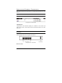
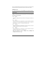
Gigabit Ethernet Switch User’s Guide Version 1.0 P/N: ATNSGD5082503 Rev.1 This User's Guide contains important information regarding the installation of your switch. Please read it completely before beginning installation. For future reference, record the serial number of your network switch in the space below: SERIAL number The serial number is located on the bottom of the switch. Amer.com 7259 Bryan Dairy Road, Largo, FL 33777 USA © Amer.com Corp., 1997-2002 All rights reserved. No part of this publication may be reproduced in any form or by any means or used to make any derivative such as translation, transformation, or adaptation without permission from Amer.com, as stipulated by the United States Copyright Act of 1976. Amer.com reserves the right to make changes to this document and the products which it describes without notice. Amer.com shall not be liable for technical or editorial errors or omissions made herein; nor for incidental or consequential damages resulting from the furnishing, performance, or use of this material. Amer.com is a registered trademark of Amer.com. All other trademarks and trade names are properties of their owners. FCC Class A Certification Statement Model SGD5 FCC Class A This device complies with Part 15 of the FCC rules. Operation is subject to the following two conditions: (1)This device may not cause harmful interference, and (2)This device must accept any interference received, including interference that may cause undesired operation. This equipment has been tested and found to comply with the limits for a Class A digital device, pursuant to Part 15 of the FCC Rules. These limits are designed to provide reasonable protection against harmful interference in a residential installation. This equipment generates, uses and can radiate radio frequency energy and, if not installed and used in accordance with the instructions, may cause harmful interference to radio communications. However, there is no guarantee that interference will not occur in a particular installation. If the equipment does cause harmful interference to radio or television reception, which can be determined by turning the equipment off and on, the user is encouraged to try to correct the interference by one or more of the following measures: . Reorient or relocate the receiving antenna. 1 . . . Increase the separation between the equipment and receiver. Connect the equipment into an outlet on a circuit different from that to which the receiver is connected to. Consult the dealer or an experienced radio/TV technician for help. Shielded interface cables must be used in order to comply with emission limits. You are cautioned that changes or modifications not expressly approved by the party responsible for compliance could void your authority to operate the equipment. For more information please contact the Federal Communication Commission. CE Mark Class A Statement In a domestic environment, this product may cause radio interference in which case the user may be required to take adequate measures. 2 TABLE OF C ONTENTS ABOUT THIS GUIDE ............................................... 4 TERMS ......................................................................................... 4 OVERVIEW OF THIS USER’S GUIDE............................................... 4 INTRODUCTION ...................................................... 5 GIGABIT ETHERNET TECHNOLOGY .............................................. 5 SWITCHING TECHNOLOGY ........................................................... 5 FEATURES .................................................................................... 6 UNPACKING AND SETUP .................................... 11 UNPACKING ............................................................................... 11 SETUP ........................................................................................ 11 IDENTIFYING EXTERNAL COMPONENTS .... 12 FRONT PANEL ............................................................................ 12 REAR PANEL .............................................................................. 12 LED INDICATORS ...................................................................... 13 TECHNICAL SPECIFICATIONS ......................... 14 P/N:1907GSW205T6380 3 ABOUT THIS GUIDE This user’s guide tells you how to install your 5-Port 1000BASE-T Gigabit Ethernet Switch, how to connect it to your Gigabit Ethernet network. Terms For simplicity, this documentation uses the terms “Switch” (first letter upper case) to refer to the 5-Port 1000BASE-T Gigabit Ethernet Switch, and “switch” (first letter lower case) to refer to all Ethernet switches, including the 5-Port 1000BASE-T Gigabit Ethernet Switch. Overview of this User’s Guide Introduction. Describes the Switch and its features. Unpacking and Setup. Helps you get started with the basic installation of the Switch. Identifying External Components. Describes the front panel, rear panel and LED indicators of the Switch. Technical Specifications. Lists all the technical specifications of the Switch. 4 INTRODUCTION This section describes the features of the 5-Port 1000BASE-T Gigabit Ethernet Switch, as well as providing some background information about Gigabit Ethernet and switching technology. Gigabit Ethernet Technology Gigabit Ethernet is an extension of IEEE 802.3 Ethernet utilizing the same packet structure, format, and support for CSMA/CD protocol, full duplex, flow control, and management objects, but with a tenfold increase in theoretical throughput over 100-Mbps Fast Ethernet and a hundredfold increase over 10-Mbps Ethernet. Since it is compatible with all 10-Mbps and 100-Mbps Ethernet environments, Gigabit Ethernet provides a straightforward upgrade without wasting a company’s existing investment in hardware, software, and trained personnel. The increased speed and extra bandwidth offered by Gigabit Ethernet is essential to coping with the network bottlenecks that frequently develop as computers and their busses get faster and more users use applications that generate more traffic. Upgrading key components, such as your backbone and servers to Gigabit Ethernet can greatly improve network response times as well as significantly speed up the traffic between your subnets. Gigabit Ethernet supports video conferencing, complex imaging, and similar data-intensive applications. Likewise, since data transfers occur 10 times faster than Fast Ethernet, servers outfitted with Gigabit Ethernet NIC’s are able to perform 10 times the number of operations in the same amount of time. Switching Technology Another key development pushing the limits of Ethernet technology is in the field of switching technology. A switch bridges Ethernet 5 packets at the MAC address level of the Ethernet protocol transmitting among connected Ethernet or fast Ethernet LAN segments. Switching is a cost-effective way of increasing the total network capacity available to users on a local area network. A switch increases capacity and decreases network loading by making it possible for a local area network to be divided into different segments which don’t compete with each other for network transmission capacity, giving a decreased load on each. The switch acts as a high-speed selective bridge between the individual segments. Traffic that needs to go from one segment to another is automatically forwarded by the switch, without interfering with any other segments. This allows the total network capacity to be multiplied, while still maintaining the same network cabling and adapter cards. Switching LAN technology is a marked improvement over the previous generation of network bridges, which were characterized by higher latencies. Routers have also been used to segment local area networks, but the cost of a router and the setup and maintenance required make routers relatively impractical. Today’s switches are an ideal solution to most kinds of local area network congestion problems. Features The 5-Port 1000BASE-T Gigabit Ethernet Switch was designed for easy installation and high performance in an environment where traffic on the network and the number of users increase continuously. 5 1000BASE-T Gigabit Ethernet ports Supports Auto-Negotiation for 10/100/1000Mbps and duplex mode Supports Auto-MDIX for each port Support Full/Half duplex transfer mode for 10 and 100Mbps 6 Support Full duplex transfer mode for 1000Mbps Full wire speed reception and transmission Store-and-Forward switching method Supports 8K absolute MAC addresses Supports 256KBytes RAM for data buffering Extensive front-panel diagnostic LEDs IEEE 802.3x flow control for full-duplex Back pressure flow control for half-duplex 7 UNPACKING AND SETUP This chapter provides unpacking and setup information for the Switch. Unpacking Open the shipping carton of the Switch and carefully unpack its contents. The carton should contain the following items: One SGD5 5-Port 1000BASE-T Gigabit Ethernet Switch Four rubber feet with adhesive backing One external power adapter This User’s Guide If any item is found missing or damaged, please contact your local supplier for replacement. Setup The setup of the Switch can be performed using the following steps: Install the Switch in a fairly cool and dry place. See Technical Specification for the acceptable operation temperature and humidity ranges. Install the Switch in a site free from strong electromagnetic source,vibration, dust,and direct sunlight. Leave at least 10cm of space at the left and right hand side of the Switch for ventilation. Visually inspect the DC power jack and make sure that it is fully secured to the power adapter. 11 IDENTIFYING EXTERNAL COMPONENTS This chapter describes the front panel, rear panel and LED indicators of the Switch Front Panel The figure below shows the front panels of the switch. Front panel view of the Switch LED Indicators Comprehensive LED indicators display the conditions of the Switch and status of the network. A description of these LED indicators follows (see LED Indicators). Rear Panel The rear panel of the Switch consists of an DC power connector. The following figure shows the rear panel of the Switch. Rear panel view of the Switch DC Power Jack: 12 Power is supplied through an external AC power adapter. Check the technical specification section for information about the AC power input voltage. 1000BASE-T Ports: Five Gigabit Ethernet ports of 10/100/1000Mbps Auto-Negotiation interface. LED Indicators The LED indicators of the Switch include Power, Link/Act, 1000Mbps and 100Mbps. The following shows the LED indicators for the Switch along with an explanation of each indicator. z POWER This indicator lights green when the Switch is receiving power, otherwise, it is off. z Link/Act These LED indicators are on when there is a secure connection (or link) to the desired port. The LED indicators blink whenever there is reception or transmission (i.e. Activity—Act) of data occurring at a port. z 1000Mbps These LED indicators are on when there is a secure connection (or link) to 1000Mbps Gigabit Ethernet device at the desired port. z 100Mbps These LED indicators are on when there is a secure connection (or link) to 100Mbps Fast Ethernet device at the desired port. When the connection (or link) is 10Mbps, both of 1000Mbps and 100Mbps LED indicators are off. 13 TECHNICAL SPECIFICATIONS General Standards: IEEE 802.3ab 1000BASE-T IEEE 802.3u 100BASE-TX IEEE 802.3 10BASE-T IEEE 802.3x Flow Control Protocol: CSMA/CD Data Transfer Rate: Ethernet: Fast Ethernet: Gigabit Ethernet: 10Mbps (Half-duplex) 20Mbps (Full-duplex) 100Mbps (Half-duplex) 200Mbps (Full-duplex) 2000Mbps (Full-duplex) Topology: Star Network Cables: Ethernet: 2-pair UTP Cat. 3,4,5, Unshield Twisted Pair (UTP )Cable Fast Ethernet: 2-pair UTP Cat. 5, Twisted Pair (UTP )Cable Unshield Gigabit Ethernet: 4-pair UTP Cat. 5, Twisted Pair (UTP )Cable Unshield Number of Ports: Five(5) 1000BASE-T Gigabit Ethernet ports 14 Physical and Environmental DC inputs: Power Consumption: Operating Temperature: Storage Temperature: Humidity: Dimensions: Certification: 7.5V 1.5A 8.5 watts maximum 0 °C ~ 40°C -10°C ~ 70°C 5% ~ 95% RH, non-condensing 171 x 98 x 29 mm (W x H x D) FCC Class A, CE Marking Class A, VCCI Class A Performance Transmission Method: RAM Buffer: Filtering Address Table: Packet Filtering/Forwarding Rate: MAC Address Learning: Store-and-forward 256K Bytes per device 8K MAC address per device Full wire speed Self-learning, auto-aging 15 Amer.com Warranty Policy Limited Lifetime Warranty In the event of a defect in quality or workmanship, Amer.com will repair or replace any hardware product sold by Amer.com with new or reconditioned parts free of charge in North America for a limited lifetime period unless otherwise specified on the sales invoice from the date of original purchase. All removed parts become the property of Amer.com. All replaced parts assume the original warranty. This warranty is extended only to the original purchaser. Proof of purchase will be required before warranty service is provided. This warranty covers only failures due to defects in quality or workmanship that occur during normal use. It does not cover damage that occurs in shipment, electrical storms, floods, dropped or other acts of nature. This warranty also does not cover any failure that results from accident, misuse, abuse, neglect, mishandling, misapplication, alteration, faulty installation, modification, computer virus, improperly installed or faulty software, or service by anyone other than an Amer.com Service Technician. If there is evidence that the failure was due to user negligence, Amer.com has the right to void this warranty and or charge normal service rates for the subject repair. The limited warranty covers a one (1) year period from date of purchase on Power Supplies, AC Adapters & Fans, after the 1 year a cost for replacement is applied to all products requiring such parts. Amer.com is not responsible for any type of data loss on hard drive or other storage devices. Warranty Service can be obtained during the warranty period by shipping, freight prepaid, or delivering the product to Amer.com in either the original package or a similar package providing an equal degree of protection. Amer.com will perform the required service and return the unit to the user (freight prepaid), if applicable, via the same mode (i.e. ground, air, etc.) 16 Limits and Expectations There are no express warranties except as listed above. Network products by Amer.com shall not be liable for incidental or consequential damages resulting from the use of this product. Any future upgrades, including (but not limited to) hardware and software are not covered by this limited warranty. If a hardware problem with this product develops during the warranty period, you may contact the Amer.com Service Center at: Telephone (727) 549-0772 Facsimile (727) 549-0992 Service Center Amer.com 7259 Bryan Dairy Road Largo, Florida 33777 U.S.A. 17