1
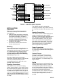
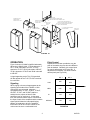
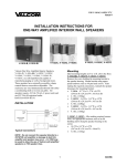
WIRE TIE LOOP
WIRE TIE USED TO B UNDLE WIRES
ENTERING AND LE AVING TERMINAL ARE A
TO REMO VE CO VER
LOOSEN SCREW ,
THE N AC TIVATE L ATC H
WIREW AY OPENING
TO W ALL PLATE AND
JUNCTIO N BOX
METAL W ALL
MO UNTING
PLATE
.155 DIA. HOLES FOR MOUNTING TO
SINGLE OR DO UBLE GANG JUNC TIO N BOX
HOLE PATTER N M ATC HES BOTH E URO
AND US JUNC TIO N BOXES
SNAP LATC H
1.5 x 2 W IRE ACCESS OPENING
TO JUNC TIO N BOX
CIRCUIT BO ARD
HO USING ASSEMBLY
PLASTIC
COVER
SNAP LATC H
FOR COVER
BRACKET
LOCKING
SCREW
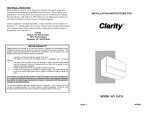
FIGURE 1A
Pitch Control
OPERATION
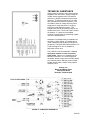
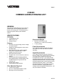
Figure 3 shows a V-9924C simplified schematic.
When the V-9924C is idle, 1T IN is shorted to 1T
OUT, 1R IN is shorted to 1R OUT, 2T IN is
shorted to 2T OUT, 2R IN is shorted to 2R OUT,
3T IN is shorted to 3T OUT and 3R IN is shorted
to 3R OUT.
Dipswitches have been provided to vary the
pitch of the warble ring tone should a different
pitch be desired. Generally, this control does
not require adjustment (see Figure 2B). If
adjustment is necessary, see chart to select
desired pitch (see Figure 2A).
A signal appearing at the T IN, R IN terminals
will also appear at the T OUT, R OUT terminals
for each zone.
BIT 1
Signaling
When ringing or buzzer voltage appears at the
signaling input leads of the V-9924C or UNA
closure pins are connected, relays are
energized and the 1T OUT, 1R OUT, 2T OUT,
2R OUT, 3T OUT, and 3R OUT leads are
switched to the outputs of three 5 Watt
amplifiers (one for each zone). At the same
time, the electronic warble tone is connected to
the input of each of the amplifiers and the warble
signal (which follows the interrupted ringing
pattern) is broadcast to all of the speakers.
Each zone has its own volume control so the
volume can be set to a comfortable level.
3
BIT 2
LOW
OFF
OFF
MED
OFF
ON
HI
ON
OFF
*DEFAULT
ON
ON
FIGURE 2A
947023