1
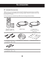
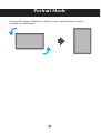
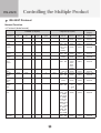
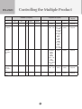
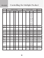
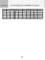
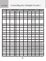
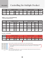
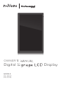
OWNER’S
S MANUAL
Digital S
Signage LCD
D Display
MODELS:
PS-420W
PS-470W
Important Precautions
Please read these safety precautions carefully before using the display.
Warning
Failure to follow those warnings may result in death, serious injury
or damage to the display or other property.
Electrical Power Related Precautions
Warning
n Use only the power cord supplied with the unit or another manufacturer’s authorized cord.
- Failure to do so may result in fire or electrical shock or damage to the display.
n Use only a properly grounded plug and receptacle.
- If you do not, you may be electrocuted or injured. Or the display might be damaged.
n Do not use a damaged or loose plug.
- This may cause electrical shock or fire.
n Operate the display only from a power source (i.e. voltage) indicated in the product
specification.
- Otherwise, the display can be damaged, fire can occur or you may be electrocuted. If you are not
sure what type of power supply you have, consult a certified electrician.
n In the presence of thunder and lightning, never touch the power cord and signal cable because
it can be very dangerous.
- It can cause electric shock.
n Do not connect several extension cords, electrical appliances or electrical heaters to a single
outlet. Use a power bar with a grounding terminal designed for exclusive use with the display.
- A fire can break out due to overheating.
n Do not touch the power plug with wet hands. Additionally, if the cord pin is wet or covered with
dust, dry the power plug completely or wipe dust off before plugging in the cord.
- You may be electrocuted due to excess moisture.
n If you do not intend to use the display for a long time, unplug the power cord from the display.
- Covering dust can cause a fire, or insulation deterioration can cause electric leakage, electric shock
or fire.
n Insert the power plug firmly so it cannot come loose.
- A loose connection can cause fire. Hold the plug when pulling out the power cord.
n Do not pull the plug out by the wire. Do not bend the power cord with excessive force or put
heavy objects on the power cord.
- The power line can be damaged, which may cause electric shock or fire.
n Do not insert metal or other conductive materials into the display openings. Additionally, do
not touch the power cord right after plugging the cable into the wall input terminal.
- You may be electrocuted.
n The power supply cord is used as the main disconnection device. The socket-outlet shall be
installed near the equipment and shall be easily accessible.
n Do not unplug the power cord while the display is in use.
- Electrical shock can damage the product.
n As long as this unit is connected to the AC wall outlet, it is not disconnected from the AC
power source even if the unit is turned off.
1
Important Precautions
Precautions in Installing the Display
Warning
n Keep away from heat sources like heaters or open flames.
- Electrical shock, fire, malfunction or deformation may occur.
n Keep the packing anti-moisture material or vinyl packing out of the reach of children.
- Anti-moisture material is harmful if swallowed. If swallowed by mistake, force the patient to vomit and
visit the nearest hospital. Additionally, vinyl packing can cause suffocation. Keep it out of the reach of
children.
n Do not put heavy objects on the display or sit upon it.
- If the display collapses or is dropped, you may be injured. Children must pay particular attention.
n Do not leave the power or signal cable where someone can trip over it.
- The passerby can falter, which can cause electrical shock, fire, display breakdown, or injury.
n Install the display in a neat and dry place. Do not use near water.
- Dust or moisture can cause electrical shock, fire, or display damage.
n Do not add accessories that have not been designed for this display.
n If you smell smoke or other odors or hear a strange sound from the display, unplug the power
cord and contact Customer Service (Please refer to the label on the rear cover).
- If you continue to use without taking proper measures, electrical shock or fire can occur.
n If you dropped the display or the case is broken, turn off the display and unplug the power
cord.
- If you continue to use without taking proper measures, electrical shock or fire can occur. Contact
Customer Service (Please refer to the label on the rear cover).
n Do not drop an object on or apply impact to the display. Do not throw any toys or objects at the
display.
- It can cause injury to humans, problems to the display, and damage the display.
n Keep out of reach of children and do not place toys near the display.
n Make sure the display ventilation hole is not blocked. Install the display more than 10cm away
from the wall.
- If you install the display too close to the wall, it may be deformed or fire can break out due to internal
heat build-up.
n Do not cover the display with cloth or other material (eg. plastic) while plugged in.
- The display can be deformed or fire can break out due to internal overheating.
n Place the display on a flat and stable surface that is large enough to support the display.
- If the display is dropped, you may be injured or the display may be broken.
n Install the display where no Electromagnetic Interference occurs.
n Keep the display away from direct sunlight.
- The display can be damaged.
n Do not place the display on the floor.
- Small children and others may trip over it.
2
Important Precautions
Precautions in Moving the Display
Warning
n Make sure to turn off the display.
- You may be electrocuted or the display can be damaged.
n Make sure to remove all cables before moving the display.
- You may be electrocuted or the display can be damaged.
n Do not shock the display when moving it.
- You may be electrocuted or the display can be damaged.
n Make sure the display faces forward and hold it with both hands to move.
- If you drop the display, the damaged display can cause electric shock or fire.
n Do not place the display face down.
- This may damage the display.
Precautions in Using/Cleaning the Display
Warning
n Do not attempt to disassemble, repair, or modify the display yourself.
- Fire or electric shock can occur.
- Contact Customer Service (Please refer to the label on the rear cover) for repair.
n When cleaning the display, unplug the power cord and scrub gently with a soft cloth to prevent
scratching. Do not clean with a wet cloth or spray water or other liquids directly onto the
display. An electric shock may occur. (Do not use chemicals such as benzene, paint thinners,
or alcohol)
n Keep the display away from water.
- Fire or electric shock accident can occur.
n Avoid high temperatures and humidity.
n Do not put or store flammable substances near the display.
- There is a danger of explosion or fire.
n Keep the display clean at all times.
n Do not press on the display with a hand or sharp object such as nail, pencil or pen, or make a
scratch on it.
n Keep proper distance from the display and rest from time-to-time.
- Your vision may be impaired if you look at the display too closely or for too long.
n Keep small accessories out of the reach of children.
n Leaving a fixed image on the display for a long time may cause damage to the display and
cause image retention. Make sure to use a screen saver on the display. Burn-in and related
problems are not covered by the warranty on this display.
n Spray water onto a soft cloth 2 to 4 times, and use it to clean the front frame; wipe in one
direction only. Too much moisture may cause staining.
3
Important Precautions
On Disposal (Only, Hg lamp used Display)
n The fluorescent lamp used in this display contains a small amount of mercury.
n Do not dispose of this display with general household waste.
n Disposal of this display must be carried out in accordance to the regulations of your local
authority.
Precautions for Image Sticking
To optimize display lifetime and function, pay attention on the following operation
usages:
n Normal operating condition
- Operating Temperature: 0°C to 40°C
- Operating Ambient Humidity: 10% to 90%
- Display Pattern: dynamic pattern (real display)
Note: Long-term static display can cause image sticking.
n Operating usages under abnormal condition
a. Ambient condition
- Well-ventilated place is recommended to set up the system.
b. Power and screen saver
- Periodical power-off or screen saver is needed after long-term display.
n Operating usages to protect against image sticking due to long-term static display
a. Suitable operating time
- Under 18 hours a day.
b. Static information display recommended to use with moving image
- Cycling display between 5 minutes information (static) display and 10 seconds moving image.
c. Background and character (image) color change
- Use different colors for background and character, respectively.
- Change colors themselves periodically.
d. Avoid combination of background and character with large different luminance
Note:
1) Abnormal condition just means conditions except normal condition.
2) Black image or moving image is strongly recommended as a screen saver.
4
Accessories
Included Accessories
Thank you for your purchase. Ensure that the following accessories are included
with your display. If an accessory is missing, please contact the dealer where you
purchased the display.
v The accessories included may differ from the images shown below.
POWER
INPUT
OK
MENU
BACKLIGHT
Remote Control &
Batteries (AAA × 2)
HDMI Cable
Power Cord
*Power Cord for EU
(Optional)
Vesa Mount Screws
(4 pcs)(Size : M6 × L20)
CD-ROM (User’s Manual)
Quick Start Guide
DMP Mount Screws
(4 pcs)(Size : M3 × L12)
5
Portrait Mode
To change the display orientation to Portrait mode, rotate the display counterclockwise as shown below.
6
Using the Remote Control
Name of the Remote Control Buttons
Input
Switch the input source.
Power
Turn the display on/off.
OK
• Enter the submenu.
• Activate the tuning bar.
• Confirm the selection.
• Display information
banner (current input
source and resolution).
Left
• Decrease the values.
• Control the tuning bar.
• Change the options.
Down
• Move downward on the
selection.
• Change selected item.
POWER
INPUT
OK
MENU
BACKLIGHT
Menu
• Display OSD (on-screen
display) menu.
• Return to the previous
menu.
• Exit OSD menu.
Up
• Move upward on the
selection.
• Change selected item.
Right
• Increase the values.
• Enter the submenu.
• Change the options.
• Control the tuning bar.
Backlight
Adjust brightness level.
Installing Batteries into the Remote Control
1. Open the battery cover.
2. Install the batteries matching the
correct polarity.
• Install two 1.5V AAA batteries.
3. Close the battery cover.
• Dispose the used batteries
in the recycle bin to prevent
environmental pollution.
7
Name and Function of the Parts
* The image shown in the user’s guide could be different from the actual image.
Front View
1
No.
2
Item
Description
1
Light sensor/
IR Receiver
Used to detect the current level of visible light in the
surrounding environment.
Receive incoming remote control commands.
2
Power indicator
Indicate power on or sleep mode status.
- Power on: Green LED lights up.
- Sleep mode: Amber LED lights up.
- Power off: LED off.
8
Name and Function of the Parts
Rear View
POWER
VIDEO
AUDIO
RS232C
AC 100-240~, 50-60Hz
External Control
OUT
POWER
POWER
IN
LEFT
LINE OUT
RIGHT
RGB IN
UP
DVI IN
DOWN
HDMI IN
MENU
OUT
INPUT
IN
AUTO/OK
3.0-1.2A
5.7-2.2A
SWITCH
VIDEO
AUDIO
RS232C
AC 100-240~, 50/60Hz
External Control
3.0-1.2A
5.7-2.2A
No.
SWITCH
IN
OUT
HDMI IN
1
2
3
4
DVI IN
5
RGB IN
LINE OUT
6
7
IN
OUT
8
Item
Description
1
AC Switch
Switch the power supply on/off.
2
AC Power Input
Connector
Connect the power cord.
3
AC Power Output Connect the AC power output.
Connector
4
HDMI Port
5
DVI Port
Connect an DVI cable to devices such as a DVD player
or set-top box.
6
RGB Port
Connect to a PC VGA port.
7
Audio system
Connect External Audio System or headphones.
8
RS-232C Serial
Ports
Connect several displays with serial port.
Connect an HDMI equipment or an HDMI-DVI adapter
cable to devices such as a DVD player or set-top box.
v HDMI Supports High Definition input and HDCP
(High-bandwidth Digital Content Protection). Some
devices require HDCP in order to display HD signals.
9
Connecting to External Devices
Recommended Connection, Resolution & Picture Mode
HDMI Connection, 1080p or 1920x1080@60Hz, dynamic
HDMI Connection (480p/576p/720p/1080i/1080p)
HDMI supports high definition input and HDCP (High-bandwidth Digital Content
Protection). Some devices require HDCP in order to display HD signals.
Display
HDMI IN
DVI IN
Display
RGB IN
LINE OUT
HDMI IN
DVI IN
RGB IN
LINE OUT
RCA-PC Audio cable
HDMI to DVI signal cable
HDMI signal cable
AUDIO
IN
VCR/DVD/Set-top Box
VCR/DVD/Set-top Box
Note: Dolby Digital is not supported.
PC Connection
Check that the computer, display, and the peripherals are turned off. Then, connect
the signal input cable.
A. Connecting with an HDMI Signal Input Cable
HDMI IN
Rear side of the display
10
Connecting to External Devices
B. Connecting with a DVI Signal Input Cable
DVI IN
Rear side of the display
C. Connecting with a D-sub(VGA) Signal Input Cable
RGB IN
PC
Rear side of the display
MAC
Macintosh Adapter
Use only the standard Macintosh adapter.
Do not use other adapter type that is compatible with different
signaling system.
Power Connection
SWITCH
IN
Power cord
Audio Out Connection
LINE OUT
Audio cable
Rear side of the display
11
POWER
AUTO/OK
LEFT
RIGHT
UP
DOWN
MENU
INPUT
Rear side of the display
Connecting to External Devices
VESA FDMI Wall Mounting
This display supports a VESA FDMI compliant mounting interface. These mounts
are purchased separately. Refer to the instructions included with the wall mount for
more info.
v The handles are designed for carrying.
Model Name
VESA-compatible wall bracket (WxH)
Mount holes number
PS-420W
200 x 200 mm
4
PS-470W
400 x 200 mm
4
POWER
AUTO/OK
LEFT
RIGHT
UP
MENU
DOWN
Handle
INPUT
Handle
PS-420W (42”)
Handle
Handle
POWER
VIDEO
AUDIO
RS232C
AC 100-240~, 50/60Hz
External Control
5.7-2.2A
3.0-1.2A
OUT
PS-470W (47”)
12
POWER
IN
AUTO/OK
LINE OUT
LEFT
RGB IN
RIGHT
DVI IN
UP
HDMI IN
DOWN
OUT
MENU
IN
INPUT
SWITCH
OSD Menus
Screen Adjustment Options (using the Control Panel)
POWER
VIDEO
AUDIO
RS232C
AC 100-240~, 50/60Hz
External Control
5.7-2.2A
LEFT
RIGHT
UP
MENU
3
DOWN
INPUT
2
6
7
POWER
LEFT
OUT
POWER
IN
RIGHT
LINE OUT
UP
RGB IN
DOWN
DVI IN
AUTO/OK
HDMI IN
AUTO/OK
3.0-1.2A
OUT
MENU
IN
INPUT
SWITCH
SWITCH
1
No.
4
5
Item
Description
1
Power switch
Turn the display on/off.
2
Input
Switch the input source.
3
Menu
Display/hide the OSD (on-screen display) menu or
return to the previous menu.
4
Down/Up
Select menu item (move up/down).
5
Right/Left
Adjust the settings (increase/decrease the value),
change the option, control the tuning bar, or enter the
submenu.
6
Auto/OK
Synchronize the display automatically.
(v only for RGB PC connection)
Enter the submenu, activate the tuning bar, or confirm
selection/setting.
7
Power
Turn the display on from standby or off to standby.
13
OSD Menus
Menu Options
PICTURE
PICTURE MODE
USER
BRIGHTNESS
50
CONTRAST
51
SHARPNESS
1
BACKLIGHT
55
COLOR TEMPERATURE
Icon
Menu
PICTURE
Adjust and refine the picture displayed on your
display based on ambient room light and personal
preferences.
SOUND
Adjust the audio settings.
SETUP
Adjust the general settings such as OSD language,
OSD rotation, and etc.
INFORMATION
Note
Description
Display the system information of the display.
OSD (On Screen Display)
The OSD function enables you to adjust the screen status conveniently
since it provides graphical presentation.
14
OSD Menus
OSD Indicator for Control Panel
For HDMI/DVI Source:
OK
For VGA Source:
AUTO
Icon
Note
Item
Description
Power
Turn on/off the display set.
AUTO
Perform AUTO function (Only VGA source).
OK
• Enter next form.
• Exit from tuning bar.
• Activate the tuning bar.
Left
• Decrease the values.
• Activate the tuning bar.
• Change the options.
Right
• Increase the values.
• Enter next form.
• Change the options.
• Activate the tuning bar.
Up
• Move the focus vertically.
• Change the selected item.
Down
• Move the focus vertically.
• Change the selected item.
Menu
• Display user menu.
• Return to last form.
• Exit user menu.
Input
Switch input sources.
If icons are colored in gray, the system is in a state such that those keys
are not active.
15
OSD Menus
Adjusting On-Screen Display (OSD) Settings
OK
OK
OK
OK
OK
OK
MENU
MENU
Display
OSD
menu
Select
a main
menu
Enter the
selected
menu
Select
a menu
item
Enter the
submenu
Adjust the
setting
Confirm
the
setting
Return
to
previous
menu
(*operation using the remote control)
1
Press the MENU button to display the OSD menu.
2
Use the p/q button to select the main menu.
3
Press the OK or u button to enter the selected menu screen.
4
Use the p/q button to select the menu item.
5
Press the OK or u button to enter the submenu.
6
Use the t/u button to adjust the setting/select the option.
7
Use the OK button to confirm the setting.
8
Press the MENU button to return to the previous menu/exit the OSD menu.
Adjusting the Screen Automatically
When the display is connected to the computer using the VGA cable, press the
Auto/OK button on the control panel to synchronize the display automatically. The
optimal screen setting will be selected to suit the current mode. If the adjustment is
not satisfactory, you can adjust the screen manually.
16
OSD Menus
Adjusting Screen Color
PICTURE
PICTURE MODE
MILD
BRIGHTNESS
50
CONTRAST
50
SHARPNESS
1
BACKLIGHT
55
COLOR TEMPERATURE
PICTURE Select a preset view option optimized for different viewing conditions.
MODE
• DYNAMIC: This mode is normally used in department store,
Backlight and Sharpness is set to its maximum value. Saturation
of Color becomes high. You can see very bright, clear, and sharp
image.
• NORMAL: This mode shows normal and natural image.
• MILD: This mode is normally used in movie. Soft image can be seen
in this mode. The picture is somewhat darker than other mode.
• USER: User can use the user-defined settings as they wish.
PICTURE
PICTURE MODE
USER
BRIGHTNESS
50
CONTRAST
51
SHARPNESS
1
BACKLIGHT
55
COLOR TEMPERATURE
BRIGHTNESS: Adjust the brightness setting.
CONTRAST: Adjust the difference between the light and dark levels in
the picture.
SHARPNESS: Adjust the sharpness of the edges of elements in the
picture.
BACKLIGHT: Adjust the backlight that affects the overall brilliance of
the picture.
Note
If the ‘PICTURE MODE’ setting in the PICTURE menu is set to
DYNAMIC, NORMAL, or MILD, the subsequent menus (BRIGHTNESS,
CONTRAST, SHARPNESS, and BACKLIGHT) will be automatically set.
17
OSD Menus
Adjusting Screen Color
PICTURE
COLOR TEMPERATURE
COLORTEMP. MODE
COLOR
TEMPERATURE
MEDIUM
RED
128
GREEN
122
BLUE
115
Adjust color settings.
• COOL: Select this option to adjust color setting to slightly
purplish white.
• MEDIUM: Select this option to adjust color setting to slightly
bluish white.
• WARM: Select this option to adjust color setting to slightly
reddish white.
• USER: Select this option to use the user-defined settings.
PICTURE
COLOR TEMPERATURE
COLORTEMP. MODE
USER
RED
128
GREEN
122
BLUE
115
RED/GREEN/BLUE: Set your own color levels.
18
OSD Menus
Adjusting Screen Color
PICTURE
DCR
OFF
BLACK LEVEL
OFF
VGA ADJUST
PICTURE RESET
DCR
Adjust the brightness of the display to maximize the picture quality.
BLACK
LEVEL
Adjust the contrast and the brightness of the display according to the
black level of the screen.
(v only for HDMI connection)
VGA
ADJUST
Adjust the PC display.
(v only for RGB PC connection)
PICTURE
AUTO ADJUST
H POSITION
50
V POSITION
50
CLOCK
50
PHASE
50
• AUTO ADJUST: Synchronize the display automatically.
• H POSITION: Move the screen position horizontally.
• V POSITION: Move the screen position vertically.
• CLOCK: Minimize any vertical bars or stripes visible on the screen
background. The horizontal screen size will also change.
• PHASE: Adjust the focus of the display. This item allows you to
remove any horizontal noise and clear or sharpen the image of
characters.
PICTURE
RESET
Reset all PICTURE settings to the factory default settings.
19
OSD Menus
Adjusting Sound Settings
SOUND
BALANCE
0
AVC
OFF
VOLUME
50
SOUND RESET
BALANCE
Use this function to balance sound from the left and right
speakers.
AVC
If this Auto Volume Control (AVC) feature is enabled, the system
will automatically adjust the uneven sound volumes across all
signals to the most appropriate level.
VOLUME
Use this function to adjust the volume control of headphone and
earphone.
SOUND
RESET
Reset all SOUND settings to the factory default settings.
20
OSD Menus
Selecting the Options
SETUP
OSD LANGUAGE
ENGLISH
OSD ROTATION
LANDSCAPE
OVERSCAN
OFF
ID SETUP
I
KEY LOCK
OFF
SCREEN SAFE
OFF
Set the on-screen display language.
OSD
LANGUAGE
OSD
ROTATION
Set the OSD menu display orientation.
OVERSCAN
Overscan function removes the noise in a video image.
(v only for HDMI-VIDEO connection)
- When ON is selected, the image size is reduced to prevent noise.
- When OFF is selected, the original image size is maintained
regardless of noise.
ID SETUP
Assign a unique Set ID NO (name assignment) to each display
when several displays are connected (via RS-232C) for display.
KEY LOCK
Enable or disable the Key Lock feature that can prevent
unauthorized viewing/operation.
If this function is enabled, long press the MENU button to unlock it.
SCREEN
SAFE
Enable or disable the screen saver feature that can prevent imagesticking.
- The white and black screens flash alternately every second.
- Disable this function when the image-sticking is disappeared.
POWER
INDICATOR
Enable or disable the power indicator on the front of the display
when the display is turned on.
DPMS
Set the power saving mode to on/off.
21
OSD Menus
Selecting the Options
ABC
If this Auto Brightness Control (ABC) feature is enabled, the system
will automatically adjust the display brightness signals based on
ambient room light.
FAIL OVER
Automatically detect the input connection and set its selection
priority.
SETUP
AUTO DETECT
ON
USER PRIORITY SETTING
PRIORITY 1
VGA
PRIORITY 2
HDMI
PRIORITY 3
DVI
If this feature is enabled (the AUTO DETECT is set to ON), you can
set the priority of the input source selection when there is more than
one input signal.
FACTORY
RESET
Return the display parameters on all menus to the factory default
settings.
22
OSD Menus
Viewing Display Information
INFORMATION
SET ID
1
F / W VERSION
2.01
SUB VERSION
7
INPUT RESOLUTION
1280x1024
60Hz
Set ID
Display the assigned ID.
F/W Version
Display the firmware version.
Sub Version
Display sub firmware version.
Input
Resolution
Show the information about resolution of the image which is
currently being displayed on the screen.
23
Troubleshooting
No image is displayed
l Is the power cord connected?
• See if the power cord is properly
connected to the outlet.
l Is the power indicator light on? • See if the power switch is turned on.
l Power is on, power indicator
is blue but the screen appears
extremely dark.
• Adjust brightness and contrast again.
l Is the power indicator amber?
• If the display is in power saving mode,
move the mouse or press any key.
• Backlight may need repair.
• Turn both devices off and then back on.
l Does the ‘NO SIGNAL’
message appear?
• The signal cable between PC and display
is not connected. Check the signal cable.
• Press INPUT on the remote control to
check the input signal.
The screen image looks abnormal
l Is the screen positioned?
• D-SUB analog signal –Press AUTO on the
control panel to automatically select the
optimal screen status that fits the current
mode. If the adjustment is not satisfactory,
use the OSD Position menu.
l Do thin lines appear in the
background?
• D-SUB analog signal –Press AUTO on the
control panel to automatically select the
optimal screen status that fits the current
mode. If the adjustment is not satisfactory,
use the Clock OSD menu.
l Power is on, power indicator
is blue but the screen appears
extremely dark.
• D-SUB analog signal –Press AUTO on the
control panel to automatically select the
optimal screen status that fits the current
mode. If the adjustment is not satisfactory,
use the OSD Phase menu.
24
Troubleshooting
After-image appears on the screen
l After-image appears when the
previous image changed.
• If you display a fixed image for a long
time, the pixels may be damaged quickly.
Use the screen-saver function.
Screen color is abnormal
l Screen has poor color
resolution (16 colors).
• Set the number of color to more than 24
bits (true color). Select Control Panel
–Display–Settings–Color Table menu in
Windows.
l Screen color is unstable or
mono-colored.
• Check the connection status of the signal
cable or re-insert the PC video card.
l Do black spots appear on the
screen?
• Several pixels (red, green, white, or
black color) may appear on the screen,
which can be attributable to the unique
characteristics of the LCD Panel. This is
not a malfunction of the LCD.
If any of above instructions does not work, follow the instructions:
[1] Press MENU > SETUP > Factory Reset.
[2] Remove the AC power cord and wait for 10 seconds.
[3] Connect the AC power cord and turn on the display.
25
Specifications
The product specifications can change without prior notice for product improvement.
LCD Panel
Display Pixels
Active Screen Size
(diagonal)
1920 (H) x 1080 (V)
Pixel Pitch
[PS-420W]: 0.4845 (H) x 0.4845(V) (mm)
[PS-470W]: 0.5415(H) x 0.5415 (V) (mm)
Rated Voltage
AC100-240 (+/- 10%) Vac at 50/60Hz
On Mode
[PS-420W]: 135 W (Typ.)
[PS-470W]: 170 W (Typ.)
Sleep Mode ≤ 0.5 W (RGB) / 0.5 W (HDMI/DVI)
Power Consumption
[PS-420W]: 42.02 inches (1067.31mm)
[PS-470W]: 46.96 inches (1192.87mm)
Off Mode 1
Power
Off Mode 2
Maximum
≤ 0.5 W (RGB) / 0.5 W (HDMI/DVI)
*Power off by using the Remote
Control or Control Panel.
≒0W
*Power off by using the AC
Power Switch.
[PS-420W]: 165 W
[PS-470W]: 225 W
H
Dimensions &
Weight
w
D
Dimensions (Width x Height x Depth)
[PS-420W]:101.3cm (39.88”) x 60.6cm (23.86”) x 8.45cm (3.33”)
[PS-470W]:112.56cm (44.31”) x 67.1cm (26.4”) x 8.76cm (3.45”)
Net Weight
[PS-420W]:13.60kg (29.98lb)
[PS-470W]:17.66kg (38.93lb)
Video Signal
Max. Resolution
Input Connector
Environmental
Conditions
RGB/HDMI/DVI: 1920 x 1080 @60 Hz
HDMI/DVI(digital), RGB (VGA), RS-232C
Operational Condition Temperature: 0°C to 40°C, Humidity: 10% to 90%
Storage Condition
Temperature: -20°C to 60°C, Humidity: 5% to 90%
26
Specifications
PC Mode (DVI/RGB) – Preset Mode
Mode Resolution Refresh Horizontal Vertical Horizontal
No.
rate (Hz) Frequency Frequency
Sync
(KHz)
(Hz)
Polarity
(TTL)
1
640 x 480
60
2
800 x 600
3
1024 x 768
4
Pixel Rate
(MHz)
Remark
N
25.175
VGA
31.469
59.941
60
37.879
60.317
P
P
40
VESA
60
48.363
60.004
N
N
65
VESA
1280 x 1024
60
63.981
60.02
P
P
108
VESA
5
1680 x 1050
60
65.29
59.954
N
P
146.25
VESA
*6
1920 x 1080
60
67.5
60
P
P
148.5
CEA
HDMI – Preset Mode
Mode No.
Resolution
1
480p
2
576p
3
720p
4
1080i
5
1080p
Power Indicator
Mode
Device
On Mode
Blue
Sleep Mode
Amber
Off Mode
-
27
N
Vertical
Sync
Polarity
(TTL)
Daisy Chain Connection
Use this method to connect several displays to a single PC.
You can control several displays at a time by connecting them to a single PC.
Connecting the cable
Connect the RS-232C cable as shown in the illustration.
* The RS-232C protocol is used for communication between the PC and display.
You can turn the display on/off or adjust the OSD menu from your PC.
RS-232C cable (not included)
IN
OUT
IN
OUT
IN
OUT
IN
OUT
PC
Display 1
Display 2
Display 3
Display 4
*Maximum of Daisy Chain: 4 pcs
RS-232C Configurations
2-Wire Configurations (Not Standard)
PC (or PD RS-232C Out)
PD (RS-232C In)
DB 9 Pin Male
5
9
1
6
2
Receive data
Input
3 TxD
Transmit data
Output
8
4 DTR
Data terminal ready
Output
9
5 GND Ground
-
6 DSR
Data set ready
Input
7 RTS
Request to send
Output
8 CTS
Clear to send
Input
9 RI
Incoming call
Input
7
3
8
6
3
4
Pin 3
4
5
9 Pin RS-232C Cable
5
9
Male
Input
2 RxD
6
2
7
Designation Description Input/Output
1 DCD Data carrier detect
1
Pin 2
Pin No.
1
Male
Communication Parameter
a Baud Rate: 9600
a Data Length: 8 Bit
a Parity Bit: None
a Stop Bit: 1 Bit
a Flow Control: None
a Communication Code: Hex Code
a Use a DB 9 Pin Cable
28
HDMI CEC Connection
With Consumer Electronics Control (CEC) feature, you can command and
control two or more CEC-enabled boxes, that are connected through HDMI, by
using only one of their remote controls. (e.g. controlling a television set, settop box and DVD player using only the remote control of the display).
Connecting the cable
Connect the HDMI cable as shown in the illustration.
HDMI IN
HDMI
Display
*Not support HDMI splitter or Daisy Chain connection, only support PC-Display 1:1
control.
HDMI CEC statement
Term
Description
One Touch Play Turning on the HDMI source device cause the connected
Display to be turned on and switch to HDMI Input
automatically.
Routing Control
Switch (Remote control or Front key) Display Input to
HDMI will cause the HDMI source device to be turned on.
System Standby Turning off the Display will cause the HDMI Devices in
the CEC net to be turned off.
29
RS-232C
Controlling the Multiple Product
RS-232C Protocol
Normal Function
a Protocol (data format).
Header (5 bytes)
Prefix code Prefix code Set Payload # of payload
Command
#0
#1
ID
Type
bytes
Set Power
0xCC
0x33
0
4
0x10
command
Ack Set
Power
Set Input
Source
Checksum
(1byte)
Payload (4 bytes)
data #0
data #1
data #2
CS #0
0 : 0ff
1 : On
0xE0 : OK
0xE1 : NG
0x30 : VGA1
0x40 : DVI1
0x50 :
HDMI1
0xE0 : OK
0xE1 : NG
reserved
(0x00)
0xE0 : OK
0xE1 : NG
reserved
(0x00)
reserved
(0xFF)
reserved
(0x00)
reserved
(0x00)
reserved
(0xFF)
reserved
(0x00)
Header XOR
Payload
Header XOR
Payload
Header XOR
Payload
reserved
(0xFF)
reserved
(0x00)
reserved
(0xFF)
Header XOR
Payload
Header XOR
Payload
Header XOR
Payload
0 : mute off
1 : mute on
0xE0 : OK
0xE1 : NG
reserved
(0xFF)
reserved
(0x00)
0x30 :
VGA1
0x40 :
DVI1
0x50 :
HDMI1
reserved
(0x00)
reserved
(0xFF)
reserved
(0x00)
reserved
(0xFF)
Header XOR
Payload
Header XOR
Payload
Header XOR
Payload
0xCC
0x55
0
4
0x10
0xCC
0x33
0
4
0x11
0xCC
0x55
0
4
0x11
0xCC
0x33
1
4
0x11
0xCC
0x55
1
4
0x11
0xCC
0x33
0
4
0x12
0xCC
0x55
0
4
0x12
0xCC
0x33
1
4
0x12
reserved
(0x00)
reserved
(0x00)
reserved
(0x00)
0xCC
0x55
1
4
0x12
0xE0 : OK
0xE1 : NG
reserved
(0xFF)
Set Fail
Over
0xCC
0x33
0
4
0x13
0 : mute
off
1 : mute
on
reserved
(0x00)
Ack Set
Fail Over
0xCC
0x55
0
4
0x13
Ack Input
Source
Read Input
Source
Ack Read
Input
Source
Set Screen
Mute
Ack Set
Screen
Mute
Read
Screen
Mute
Ack Read
Screen
Mute
A1
0 : off
Other : ON
1 : HDMI,
DVI, Dsub
2 : HDMI,
Dsub, DVI
3 : DVI,
HDMI, Dsub
4 : DVI,
Dsub, HDMI
5 : Dsub,
HDMI, DVI
6 : Dsub,
DVI, HDMI
0xE0 : OK reserved
0xE1 : NG
(0xFF)
reserved
(0x00)
Header XOR
Payload
reserved
(0xFF)
Header XOR
Payload
RS-232C
Controlling the Multiple Product
Header (5 bytes)
command
Read Fail
Over
Ack Read
Fail Over
Checksum
(1byte)
Payload (4 bytes)
Prefix code Prefix code Set Payload # of payload
Command
#0
#1
ID
Type
bytes
0xCC
0x33
1
4
0x13
0xCC
0x55
1
4
0x13
Set
Remote
Controller
Key
0xCC
0x33
0
4
0x14
Ack Set
Remote
Controller
Key
Read
Abnomal
State
0xCC
0x55
0
4
0x14
0xCC
0x33
1
4
0x17
A2
data #0
data #1
reserved
reserved
(0x00)
(0x00)
0xE0 : OK
0 : off
0xE1 : NG Other : ON
1 : HDMI,
DVI, Dsub
2 : HDMI,
Dsub, DVI
3 : DVI,
HDMI,
Dsub
4 : DVI,
Dsub,
HDMI
5 : Dsub,
HDMI,
DVI
6 : Dsub,
DVI, HDMI
0x08 :
reserved
POWER
(0x00)
0x43 :
MENU
0x0B :
INPUT
0x40 : UP
0x41 :
DOWN
0x07 : LEFT
0x06 :
RIGHT
0xE0 : OK reserved
0xE1 : NG
(0xFF)
reserved
(0x00)
reserved
(0x00)
data #2
CS #0
reserved
(0x00)
reserved
(0xFF)
Header XOR
Payload
Header XOR
Payload
reserved
(0x00)
Header XOR
Payload
reserved
(0xFF)
Header XOR
Payload
reserved
(0x00)
Header XOR
Payload
RS-232C
Controlling the Multiple Product
Header (5 bytes)
command
Ack Read
Abnormal
State
Prefix code Prefix code Set Payload # of payload
Command
#0
#1
ID
Type
bytes
0xCC
0x55
1
4
0x17
Read Lamp
fault State
Ack Read
Lamp fault
State
0xCC
0x33
1
4
0x18
0xCC
0x55
1
4
0x18
Set DCR
0xCC
0x33
0
4
0xA0
Ack Set
DCR
Read DCR
0xCC
0x55
0
4
0xA0
0xCC
0x33
1
4
0xA1
0xCC
0x55
1
4
0xA1
0xCC
0x33
1
4
0xA2
0xCC
0x55
1
4
0xA2
0xCC
0x33
1
4
0xA3
0xCC
0x55
1
4
0xA3
0xCC
0x33
1
4
0xA4
0xCC
0x55
1
4
0xA4
Ack Read
DCR
Read Sub
Version
Ack Read
Sub
Version
Read Input
Resolution
Ack Read
Input
Resolution
Read Lamp
on time
Ack Read
Lamp on
time
Checksum
(1byte)
Payload (4 bytes)
A3
data #0
data #1
0xE0 : OK 0 : Normal
0xE1 : NG (power on
and signal
exist)
1 : No
Signal
(power
on)
2 : Turn off
by remote
controller
3 : Turn
off by local
key
4 : Turn
off by
RS-232C
function
reserved
reserved
(0x00)
(0x00)
0xE0 : OK 0 : lamp
0xE1 : NG
fault
1 : lamp
OK
0 : Off
reserved
1 : On
(0x00)
0xE0 : OK reserved
0xE1 : NG
(0xFF)
reserved
reserved
(0x00)
(0x00)
0xE0 : OK
0 : Off
0xE1 : NG
1 : On
reserved
reserved
(0x00)
(0x00)
0xE0 : OK (Version
0xE1 : NG
No.)
reserved
(0x00)
Hwidth
bit(11:4)
reserved
(0x00)
0xE0 : OK
0xE1 : Ng
reserved
(0x00)
bit(7:4)
Hwidth
bit(3:0)
bit(3:0)
Vheight
bit(11:8)
reserved
(0x00)
lapm on
time high
bit(15:8)
data #2
CS #0
reserved
(0xFF)
Header XOR
Payload
reserved
(0x00)
reserved
(0xFF)
Header XOR
Payload
Header XOR
Payload
reserved
(0x00)
reserved
(0xFF)
reserved
(0x00)
reserved
(0xFF)
reserved
(0x00)
reserved
(0xFF)
Header XOR
Payload
Header XOR
Payload
Header XOR
Payload
Header XOR
Payload
Header XOR
Payload
Header XOR
Payload
reserved
(0x00)
Vheight
bit(7:0)
Header XOR
Payload
Header XOR
Payload
reserved
(0x00)
lapm on
time low
bit(7:0)
Header XOR
Payload
Header XOR
Payload
RS-232C
Controlling the Multiple Product
Header (5 bytes)
command
Set CEC
Ack Set
CEC
Read CEC
Ack Read
CEC
Checksum
(1byte)
Payload (4 bytes)
Prefix code Prefix code Set Payload # of payload
Command
#0
#1
ID
Type
bytes
0xCC
0x33
0
4
0xA5
0xCC
0x55
0
4
0xA5
0xCC
0x33
1
4
0xA6
0xCC
0x55
1
4
0xA6
A4
data #0
data #1
data #2
CS #0
0 : Off
1 : On
0xE0 : OK
0xE1 : NG
reserved
(0x00)
0xE0 : OK
0xE1 : NG
reserved
(0x00)
reserved
(0xFF)
reserved
(0x00)
0 : Off
1 : On
reserved
(0x00)
reserved
(0xFF)
reserved
(0x00)
reserved
(0xFF)
Header XOR
Payload
Header XOR
Payload
Header XOR
Payload
Header XOR
Payload
RS-232C
Controlling the Multiple Product
MENU function (PICTURE)
a Protocol (data format).
Header (5 bytes)
Prefix code Prefix code
#0
#1
Set Picture
0xCC
0x33
Mode
command
Ack Set
Picture
Mode
Read
Picture
Mode
Ack Read
Picture
Mode
Set
Brightness
Ack Set
Brightness
Read
Brightness
Ack Read
Brightness
Set
Contrast
Ack Set
Contrast
Read
Contrast
Ack Read
Contrast
Set
Sharpness
Ack Set
Sharpness
Read
Sharpness
Ack Read
Sharpness
Set
Backlight
Ack Set
Backlight
Read
Backlight
Ack Read
Backlight
Set Color
Temp
Mode
Set
ID
Checksum
(1byte)
Payload (4 bytes)
Payload # of payload
Command
data #0
data #1
Type
bytes
0
4
0x30
0 : Dynamic reserved
1 : Normal
(0x00)
2 : Mild
3 : User
0
4
0x30
0xE0 : OK reserved
0xE1 : NG
(0xFF)
0xCC
0x55
0xCC
0x33
1
4
0x30
reserved
(0x00)
0xCC
0x55
1
4
0x30
0xE0 : OK
0xE1 : NG
0xCC
0x33
0
4
0x31
0xCC
0x55
0
4
0x31
0xCC
0x33
1
4
0x31
0xCC
0x55
1
4
0x31
0xCC
0x33
0
4
0x32
0xCC
0x55
0
4
0x32
0xCC
0x33
1
4
0x32
0xCC
0x55
1
4
0x32
0xCC
0x33
0
4
0x33
0xCC
0x55
0
4
0x33
0xCC
0x33
1
4
0x33
0xCC
0x55
1
4
0x33
0xCC
0x33
0
4
0x34
0xCC
0x55
0
4
0x34
0xCC
0x33
1
4
0x34
0xCC
0x55
1
4
0x34
0xCC
0x33
0
4
0x35
A5
reserved
(0x00)
0:
Dynamic
1 : Normal
2 : Mild
3 : User
0~100
reserved
(0x00)
0xE0 : OK reserved
0xE1 : NG
(0xFF)
reserved
reserved
(0x00)
(0x00)
0xE0 : OK
0~100
0xE1 : NG
0~100
reserved
(0x00)
0xE0 : OK reserved
0xE1 : NG
(0xFF)
reserved
reserved
(0x00)
(0x00)
0xE0 : OK
0~100
0xE1 : NG
0~4
reserved
(0x00)
0xE0 : OK reserved
0xE1 : NG
(0xFF)
reserved
reserved
(0x00)
(0x00)
0xE0 : OK
0~4
0xE1 : NG
0~100
reserved
(0x00)
0xE0 : OK reserved
0xE1 : NG
(0xFF)
reserved
reserved
(0x00)
(0x00)
0xE0 : OK
0~100
0xE1 : NG
0 : Cool
reserved
1 : Medium
(0x00)
2 : Warm
3 : User
data #2
CS #0
reserved Header XOR
(0x00)
Payload
reserved Header XOR
(0xFF)
Payload
reserved Header XOR
(0x00)
Payload
reserved Header XOR
(0xFF)
Payload
reserved
(0x00)
reserved
(0xFF)
reserved
(0x00)
reserved
(0xFF)
reserved
(0x00)
reserved
(0xFF)
reserved
(0x00)
reserved
(0xFF)
reserved
(0x00)
reserved
(0xFF)
reserved
(0x00)
reserved
(0xFF)
reserved
(0x00)
reserved
(0xFF)
reserved
(0x00)
reserved
(0xFF)
reserved
(0x00)
Header XOR
Payload
Header XOR
Payload
Header XOR
Payload
Header XOR
Payload
Header XOR
Payload
Header XOR
Payload
Header XOR
Payload
Header XOR
Payload
Header XOR
Payload
Header XOR
Payload
Header XOR
Payload
Header XOR
Payload
Header XOR
Payload
Header XOR
Payload
Header XOR
Payload
Header XOR
Payload
Header XOR
Payload
RS-232C
Controlling the Multiple Product
Header (5 bytes)
command
Ack Set
Color Temp
Mode
Read Color
Temp
Mode
Ack Read
Color Temp
Mode
Set Color
Temp Red
Ack Set
Color Temp
Red
Read Color
Temp Red
Ack Read
Color Temp
Red
Set Color
Temp
Green
Ack Set
Color Temp
Green
Read Color
Temp
Green
Ack Read
Color Temp
Green
Set Color
Temp Blue
Ack Set
Color Temp
Blue
Read Color
Temp Blue
Ack Read
Color Temp
Blue
Set Black
Level
Ack Set
Black Level
Read Black
Level
Ack Read
Black Level
Set VGA
Adjust Auto
Mode
Prefix code Prefix code
#0
#1
0xCC
0x55
Set
ID
Checksum
(1byte)
Payload (4 bytes)
Payload # of payload
Command
Type
bytes
0
4
0x35
0xCC
0x33
1
4
0x35
0xCC
0x55
1
4
0x35
0xCC
0x33
0
4
0x36
0xCC
0x55
0
4
0x36
0xCC
0x33
1
4
0x36
0xCC
0x55
1
4
0x36
0xCC
0x33
0
4
0xCC
0x55
0
0xCC
0x33
0xCC
data #0
data #1
data #2
CS #0
0xE0 : OK
0xE1 : NG
reserved
(0xFF)
reserved Header XOR
(0xFF)
Payload
reserved
(0x00)
reserved
(0x00)
reserved Header XOR
(0x00)
Payload
0xE0 : OK
0 : Cool reserved Header XOR
Payload
0xE1 : NG 1 : Medium (0xFF)
2 : Warm
3 : User
0 ~ 255
reserved reserved Header XOR
(0x00)
(0x00)
Payload
0xE0 : OK reserved reserved Header XOR
0xE1 : NG
(0xFF)
(0xFF)
Payload
reserved
(0x00)
0xE0 : OK
0xE1 : NG
reserved
(0x00)
0 ~ 255
reserved Header XOR
(0x00)
Payload
reserved Header XOR
(0xFF)
Payload
0x37
0 ~ 255
reserved
(0x00)
reserved Header XOR
(0x00)
Payload
4
0x37
0xE0 : OK
0xE1 : NG
reserved
(0xFF)
reserved Header XOR
(0xFF)
Payload
1
4
0x37
reserved
(0x00)
reserved
(0x00)
reserved Header XOR
(0x00)
Payload
0x55
1
4
0x37
0xE0 : OK
0xE1 : NG
0 ~ 255
reserved Header XOR
(0xFF)
Payload
0xCC
0x33
0
4
0x38
0 ~ 255
0xCC
0x55
0
4
0x38
0xE0 : OK
0xE1 : NG
reserved
(0x00)
reserved
(0xFF)
reserved Header XOR
(0x00)
Payload
reserved Header XOR
(0xFF)
Payload
0xCC
0x33
1
4
0x38
0xCC
0x55
1
4
0x38
reserved
(0x00)
0xE0 : OK
0xE1 : NG
reserved
(0x00)
0 ~ 255
reserved Header XOR
(0x00)
Payload
reserved Header XOR
(0xFF)
Payload
0xCC
0x33
0
4
0x39
0xCC
0x55
0
4
0x39
0xCC
0x33
1
4
0x39
0xCC
0x55
1
4
0x39
0xCC
0x33
0
4
0x3A
0 : Low
1 : High
0xE0 : OK
0xE1 : NG
reserved
(0x00)
0xE0 : OK
0xE1 : NG
reserved
(0x00)
reserved
(0x00)
reserved
(0xFF)
reserved
(0x00)
0 : Low
1 : High
reserved
(0x00)
reserved
(0x00)
reserved
(0xFF)
reserved
(0x00)
reserved
(0xFF)
reserved
(0x00)
A6
Header XOR
Payload
Header XOR
Payload
Header XOR
Payload
Header XOR
Payload
Header XOR
Payload
RS-232C
Controlling the Multiple Product
Header (5 bytes)
command
Ack Set
VGA Adjust
Auto Mode
Set VGA
Adjust H
Position
Ack Set
VGA adjust
H Position
Read VGA
Adjust H
Position
Ack Read
VGA Adjust
H Position
Set VGA
Adjust V
Position
Ack Set
VGA Adjust
V Position
Read VGA
Adjust V
Position
Ack Read
VGA Adjust
V Position
Set VGA
Adjust
Clock
Ack Set
VGA Adjust
Clock
Read VGA
Adjust
Clock
Ack Read
VGA Adjust
Clock
Set VGA
Adjust
Phase
Ack Set
VGA Adjust
Phase
Read VGA
Adjust
Phase
Ack Read
VGA Adjust
Phase
Set Picture
Reset
Ack Set
Picture
Reset
Prefix code Prefix code
#0
#1
0xCC
0x55
Set
ID
Checksum
(1byte)
Payload (4 bytes)
Payload # of payload
Command
Type
bytes
0
4
0x3A
data #0
data #1
data #2
0xE0 : OK
0xE1 : NG
reserved
(0xFF)
reserved Header XOR
(0xFF)
Payload
CS #0
0xCC
0x33
0
4
0x3B
0~100
reserved
(0x00)
reserved Header XOR
(0x00)
Payload
0xCC
0x55
0
4
0x3B
0xE0 : OK
0xE1 : NG
reserved
(0xFF)
reserved Header XOR
(0xFF)
Payload
0xCC
0x33
1
4
0x3B
reserved
(0x00)
reserved
(0x00)
reserved Header XOR
(0x00)
Payload
0xCC
0x55
1
4
0x3B
0xE0 : OK
0xE1 : NG
1~100
reserved Header XOR
(0xFF)
Payload
0xCC
0x33
0
4
0x3C
0~100
reserved
(0x00)
reserved Header XOR
(0x00)
Payload
0xCC
0x55
0
4
0x3C
0xE0 : OK
0xE1 : NG
reserved
(0xFF)
reserved Header XOR
(0xFF)
Payload
0xCC
0x33
1
4
0x3C
reserved
(0x00)
reserved
(0x00)
reserved Header XOR
(0x00)
Payload
0xCC
0x55
1
4
0x3C
0xE0 : OK
0xE1 : NG
1~100
reserved Header XOR
(0xFF)
Payload
0xCC
0x33
0
4
0x3D
0~100
reserved
(0x00)
reserved Header XOR
(0x00)
Payload
0xCC
0x55
0
4
0x3D
0xE0 : OK
0xE1 : NG
reserved
(0xFF)
reserved Header XOR
(0xFF)
Payload
0xCC
0x33
1
4
0x3D
reserved
(0x00)
reserved
(0x00)
reserved Header XOR
(0x00)
Payload
0xCC
0x55
1
4
0x3D
0xE0 : OK
0xE1 : NG
1~100
reserved Header XOR
(0xFF)
Payload
0xCC
0x33
0
4
0x3E
0~100
reserved
(0x00)
reserved Header XOR
(0x00)
Payload
0xCC
0x55
0
4
0x3E
0xE0 : OK
0xE1 : NG
reserved
(0xFF)
reserved Header XOR
(0xFF)
Payload
0xCC
0x33
1
4
0x3E
reserved
(0x00)
reserved
(0x00)
reserved Header XOR
(0x00)
Payload
0xCC
0x55
1
4
0x3E
0xE0 : OK
0xE1 : NG
1~100
reserved Header XOR
(0xFF)
Payload
0xCC
0x33
0
4
0x3F
0xCC
0x55
0
4
0x3F
reserved
(0x00)
0xE0 : OK
0xE1 : NG
reserved
(0x00)
reserved
(0xFF)
reserved Header XOR
(0x00)
Payload
reserved Header XOR
(0xFF)
Payload
A7
RS-232C
Controlling the Multiple Product
MENU function (SOUND)
a Protocol (data format).
Header (5 bytes)
command
Set
Balance
Ack Set
Balance
Read
Balance
Ack Read
Balance
Prefix code Prefix code Set Payload # of payload
Command
#0
#1
ID
Type
bytes
0xCC
0x33
0
4
0x56
0xCC
0x55
0
4
0x56
0xCC
0x33
1
4
0x56
0xCC
0x55
1
4
0x56
Set AVC
0xCC
0x33
0
4
0x57
Ack Set
AVC
Read AVC
0xCC
0x55
0
4
0x57
0xCC
0x33
1
4
0x57
0xCC
0x55
1
4
0x57
0xCC
0x33
0
4
0x58
0xCC
0x55
0
4
0x58
0xCC
0x33
1
4
0x58
0xCC
0x55
1
4
0x58
0xCC
0x33
0
4
0x59
0xCC
0x55
0
4
0x59
Ack Read
AVC
Set Volume
Ack Set
Volume
Read
Volume
Ack Read
Volume
Set Sound
Reset
Ack Set
Sound
Reset
Checksum
(1byte)
Payload (4 bytes)
A8
data #0
data #1
data #2
CS #0
0 : L50
~
49 : L1
50 : 0
51 : R1
~
100 : R50
0xE0 : OK
0xE1 : NG
reserved
(0x00)
0xE0 : OK
0xE1 : NG
reserved
(0x00)
reserved
(0x00)
Header XOR
Payload
reserved
(0xFF)
reserved
(0x00)
0 : L50
~
49 : L1
50 : 0
51 : R1
~
100 : R50
reserved
(0x00)
reserved
(0xFF)
reserved
(0x00)
0 : Off
1 : On
reserved
(0x00)
reserved
(0xFF)
reserved
(0x00)
0~100
reserved
(0xFF)
reserved
(0x00)
reserved
(0xFF)
Header XOR
Payload
Header XOR
Payload
Header XOR
Payload
reserved
(0x00)
reserved
(0xFF)
reserved
(0x00)
reserved
(0xFF)
reserved
(0x00)
reserved
(0xFF)
reserved
(0x00)
reserved
(0xFF)
reserved
(0x00)
reserved
(0xFF)
Header XOR
Payload
Header XOR
Payload
Header XOR
Payload
Header XOR
Payload
Header XOR
Payload
Header XOR
Payload
Header XOR
Payload
Header XOR
Payload
Header XOR
Payload
Header XOR
Payload
0 : Off
1 : On
0xE0 : OK
0xE1 : NG
reserved
(0x00)
0xE0 : OK
0xE1 : NG
0~100
0xE0 : OK
0xE1 : NG
reserved
(0x00)
0xE0 : OK
0xE1 : NG
reserved
(0x00)
0xE0 : OK
0xE1 : NG
reserved
(0x00)
reserved
(0xFF)
RS-232C
Controlling the Multiple Product
MENU function (SETUP)
a Protocol (data format).
Header (5 bytes)
command
Set OSD
Language
Prefix code Prefix code
#0
#1
0xCC
0x33
Set
ID
Payload # of payload
Command
Type
bytes
0
4
0x70
0xCC
0x55
0
4
0x70
0xCC
0x33
1
4
0x70
0xCC
0x55
1
4
0x70
Set OSD
Rotation
0xCC
0x33
0
4
0x71
Ack Set
OSD
Rotation
Read OSD
Rotation
Ack Read
OSD
Rotation
Set
Overscan
Ack Set
Overscan
Read
Overscan
Ack Read
Overscan
Set ID
Setup
Ack Set ID
Setup
0xCC
0x55
0
4
0x71
0xCC
0x33
1
4
0x71
0xCC
0x55
1
4
0x71
0xCC
0x33
0
4
0x72
0xCC
0x55
0
4
0x72
0xCC
0x33
1
4
0x72
0xCC
0x55
1
4
0x72
0xCC
0x33
0
4
0x73
0xCC
0x55
0
4
0x73
Ack Set
OSD
Language
Read OSD
Language
Ack Read
OSD
Language
Checksum
(1byte)
Payload (4 bytes)
A9
data #0
data #1
data #2
CS #0
0 : English reserved
1 : Spanish
(0x00)
2 : French
3 : Italian
4 : Deutsch
5 : Polski
6:
Portuques
7 : Chinese
8 : Japanese
9 : Korean
0xE0 : OK reserved
0xE1 : NG
(0xFF)
reserved
(0x00)
Header XOR
Payload
reserved
(0xFF)
Header XOR
Payload
reserved
(0x00)
reserved
(0xFF)
Header XOR
Payload
Header XOR
Payload
reserved
(0x00)
Header XOR
Payload
reserved
(0xFF)
Header XOR
Payload
reserved
(0x00)
reserved
(0xFF)
Header XOR
Payload
Header XOR
Payload
reserved
(0x00)
reserved
(0xFF)
reserved
(0x00)
reserved
(0xFF)
reserved
(0x00)
reserved
(0xFF)
Header XOR
Payload
Header XOR
Payload
Header XOR
Payload
Header XOR
Payload
Header XOR
Payload
Header XOR
Payload
reserved
reserved
(0x00)
(0x00)
0xE0 : OK 0 : English
0xE1 : NG 1 : Spanish
2 : French
3 : Italian
4 : Deutsch
5 : Polski
6:
Portuques
7 : Chinese
8:
Japanese
9 : Korean
0:
reserved
Landscape
(0x00)
1 : Portrait
0xE0 : OK reserved
0xE1 : NG
(0xFF)
reserved
reserved
(0x00)
(0x00)
0xE0 : OK
0:
0xE1 : NG Landscape
1 : Portrait
0 : Off
reserved
1 : On
(0x00)
0xE0 : OK reserved
0xE1 : NG
(0xFF)
reserved
reserved
(0x00)
(0x00)
0xE0 : OK
0 : Off
0xE1 : NG
1 : On
1~100
reserved
(0x00)
0xE0 : OK reserved
0xE1 : NG
(0xFF)
RS-232C
Controlling the Multiple Product
Header (5 bytes)
command
Set Key
Lock
Ack Set
Key Lock
Read Key
Lock
Ack Read
Key Lock
Set Screen
Safe
Ack Set
Screen
Safe
Read
Screen
Safe
Ack Read
Screen
Safe
Set Power
Indicator
Ack Set
Power
Indicator
Read
Power
Indicator
Ack Read
Power
Indicator
Set DPMS
Ack Set
DPMS
Read
DPMS
Ack Read
DPMS
Set ABC
Ack Set
ABC
Read ABC
Ack Read
ABC
Set Factory
Reset
Prefix code Prefix code
#0
#1
0xCC
0x33
Set
ID
Checksum
(1byte)
Payload (4 bytes)
Payload # of payload
Command
data #0
Type
bytes
0
4
0x74
0 : Off (Front
key unlock)
1 : On (Front
key lock)
0
4
0x74
0xE0 : OK
0xE1 : NG
1
4
0x74
reserved
(0x00)
1
4
0x74
0xE0 : OK
0xE1 : NG
data #1
data #2
CS #0
reserved
(0x00)
reserved
(0x00)
Header XOR
Payload
reserved
(0xFF)
reserved
(0x00)
reserved
(0xFF)
Header XOR
Payload
Header XOR
Payload
Header XOR
Payload
0 : Off
1 : On
0xE0 : OK
0xE1 : NG
reserved
(0xFF)
reserved
(0x00)
0 : Off
(Front key
unlock)
1 : On
(Front key
lock)
reserved
(0x00)
reserved
(0xFF)
reserved
(0x00)
reserved
(0xFF)
Header XOR
Payload
Header XOR
Payload
0xCC
0x55
0xCC
0x33
0xCC
0x55
0xCC
0x33
0
4
0x75
0xCC
0x55
0
4
0x75
0xCC
0x33
1
4
0x75
reserved
(0x00)
reserved
(0x00)
reserved
(0x00)
Header XOR
Payload
0xCC
0x55
1
4
0x75
0xE0 : OK
0xE1 : NG
0 : Off
1 : On
reserved
(0xFF)
Header XOR
Payload
0xCC
0x33
0
4
0x76
0xCC
0x55
0
4
0x76
0 : Off
1 : On
0xE0 : OK
0xE1 : NG
reserved
(0x00)
reserved
(0xFF)
reserved
(0x00)
reserved
(0xFF)
Header XOR
Payload
Header XOR
Payload
0xCC
0x33
1
4
0x76
reserved
(0x00)
reserved
(0x00)
reserved
(0x00)
Header XOR
Payload
0xCC
0x55
1
4
0x76
0xE0 : OK
0xE1 : NG
0 : Off
1 : On
reserved
(0xFF)
Header XOR
Payload
0xCC
0x33
0
4
0x77
0xCC
0x55
0
4
0x77
0xCC
0x33
1
4
0x77
0xCC
0x55
1
4
0x77
0xCC
0x33
0
4
0x78
0xCC
0x55
0
4
0x78
0xCC
0x33
1
4
0x78
0xCC
0x55
1
4
0x78
0xCC
0x33
0
4
0x79
0 : Off
1 : On
0xE0 : OK
0xE1 : NG
reserved
(0x00)
0xE0 : OK
0xE1 : NG
0 : Off
1 : On
0xE0 : OK
0xE1 : NG
reserved
(0x00)
0xE0 : OK
0xE1 : NG
reserved
(0x00)
reserved
(0x00)
reserved
(0xFF)
reserved
(0x00)
0 : Off
1 : On
reserved
(0x00)
reserved
(0xFF)
reserved
(0x00)
0 : Off
1 : On
reserved
(0x00)
reserved
(0x00)
reserved
(0xFF)
reserved
(0x00)
reserved
(0xFF)
reserved
(0x00)
reserved
(0xFF)
reserved
(0x00)
reserved
(0xFF)
reserved
(0x00)
Header XOR
Payload
Header XOR
Payload
Header XOR
Payload
Header XOR
Payload
Header XOR
Payload
Header XOR
Payload
Header XOR
Payload
Header XOR
Payload
Header XOR
Payload
A10
RS-232C
Controlling the Multiple Product
Header (5 bytes)
command
Ack Set
Factory
Reset
Prefix code Prefix code
#0
#1
0xCC
0x55
Set
ID
Checksum
(1byte)
Payload (4 bytes)
Payload # of payload
Command
Type
bytes
0
4
0x79
data #0
data #1
data #2
CS #0
0xE0 : OK
0xE1 : NG
reserved
(0xFF)
reserved
(0xFF)
Header XOR
Payload
MENU function (INFORMATION)
a Protocol (data format).
Header (5 bytes)
command
Read Set
ID
Ack Read
Set ID
Read F/W
Version
Ack Read
F/W
Version
Prefix code Prefix code
#0
#1
0xCC
0x33
Set
ID
Checksum
(1byte)
Payload (4 bytes)
Payload # of payload
Command
Type
bytes
1
4
0x90
0xCC
0x55
1
4
0x90
0xCC
0x33
1
4
0x91
0xCC
0x55
1
4
0x91
data #0
data #1
reserved
(0x00)
0xE0 : OK
0xE1 : NG
reserved
(0x00)
0xE0 : OK
0xE1 : NG
reserved
(0x00)
1~100
data #2
reserved
(0x00)
reserved
(0xFF)
reserved reserved
(0x00)
(0x00)
F/WLeft F/W Right
part
part
CS #0
Header XOR
Payload
Header XOR
Payload
Header XOR
Payload
Header XOR
Payload
RS232C CheckSum
Header (5 bytes)
Prefix code Prefix code
#0
#1
Set Power
0xCC
0x33
command
Set
ID
Checksum
(1byte)
Payload (4 bytes)
Payload # of payload
Command
Type
bytes
0
4
0x10
data #0
data #1
data #2
CS #0
0 : 0ff
1 : On
reserved
(0x00)
reserved Header XOR
(0x00)
Payload
We can make CheckSum with Header (5 bytes) and Payload(4 bytes).
(Prefix code#0) XOR (Prefix code#1) XOR (Set ID) XOR (Command Payload Type) XOR
(# of Payload bytes) XOR (Command) XOR (data #0) XOR (data #1) XOR (data#2) =
CheckSum
For example:
(0xCC) XOR (0x33) XOR (0x01 = Set ID) XOR (0x00) XOR (0x04) XOR (0x10) XOR (0x01 =
ON) XOR (0x00) XOR (0x00) = 0xEB
A11
HDMI CEC
HDMI Consumer Electronics Control
HDMI CEC Protocol
Normal Function
a Vendor Specific Data.
Vendor Specific Data
OPCODE
command
Vendor
Command
With ID
Set Power
0xA0
Ack Set Power
0xA0
Set Input Source
0xA0
Ack Input Source
0xA0
Read Input
Source
Ack Read Input
Source
0xA0
Set Screen Mute
0xA0
Ack Set Screen
Mute
Read Screen
Mute
Ack Read Screen
Mute
Set Fail Over
0xA0
0xA0
Ack Set Fail Over
0xA0
0xA0
0xA0
0xA0
VENDOR ID
Header (2 bytes) Payload (fixed bytes : 3 bytes)
VENDOR ID Set
(3bytes)
ID
0x3C 0xE6
0x24
0x3C 0xE6
0x24
0x3C 0xE6
0x24
0x3C 0xE6
0x24
0x3C 0xE6
0x24
0x3C 0xE6
0x24
0x3C 0xE6
0x24
0x3C 0xE6
0x24
0x3C 0xE6
0x24
0x3C 0xE6
0x24
0x3C 0xE6
0x24
0x3C 0xE6
0x24
Checksum
(1byte)
Payload
Type
Command
data #0
data #1
CS #0
0
0x10
4
0x10
0
0x11
reserved
(0x00)
reserved
(0xFF)
reserved
(0x00)
Header XOR
Payload
Header XOR
Payload
Header XOR
Payload
4
0x11
1
0x11
5
0x11
0 : 0ff
1 : On
0xE0 : OK
0xE1 : NG
0x30 : VGA1
0x40 : DVI1
0x50 :
HDMI1
0xE0 : OK
0xE1 : NG
reserved
(0x00)
0xE0 : OK
0xE1 : NG
Header XOR
Payload
Header XOR
Payload
Header XOR
Payload
0
0x12
4
0x12
1
0x12
5
0x12
0
0x13
reserved
(0xFF)
reserved
(0x00)
0x30 :
VGA1
0x40 : DVI1
0x50 :
HDMI1
reserved
(0x00)
reserved
(0xFF)
reserved
(0x00)
0 : mute off
1 : mute on
reserved
(0x00)
Header XOR
Payload
0
0x13
reserved
(0xFF)
Header XOR
Payload
A12
0 : mute off
1 : mute on
0xE0 : OK
0xE1 : NG
reserved
(0x00)
0xE0 : OK
0xE1 : NG
0 : off
Other : ON
1 : HDMI,
DVI, Dsub
2 : HDMI,
Dsub, DVI
3 : DVI,
HDMI, Dsub
4 : DVI,
Dsub, HDMI
5 : Dsub,
HDMI, DVI
6 : Dsub,
DVI, HDMI
0xE0 : OK
0xE1 : NG
Header XOR
Payload
Header XOR
Payload
Header XOR
Payload
HDMI CEC
HDMI Consumer Electronics Control
OPCODE
command
Vendor
Command
With ID
VENDOR ID
Vendor Specific Data
Header (2 bytes) Payload (fixed bytes : 3 bytes)
VENDOR ID Set
(3bytes)
ID
Payload
Type
Command
0x3C 0xE6
0x24
0x3C 0xE6
0x24
1
0x13
1
0x13
Read Fail Over
0xA0
Ack Read Fail
Over
0xA0
Set Remote
Controller Key
0xA0
0x3C 0xE6
0x24
0
0x14
Ack Set Remote
Controller Key
Read Abnomal
State
Ack Read
Abnormal State
0xA0
0x3C 0xE6
0x24
0x3C 0xE6
0x24
0x3C 0xE6
0x24
4
0x14
1
0x17
5
0x17
1
0x18
5
0x18
Read Lamp fault
State
Ack Read Lamp
fault State
0xA0
0xA0
0xA0
0xA0
0x3C 0xE6
0x24
0x3C 0xE6
0x24
A13
data #0
data #1
reserved
reserved
(0x00)
(0x00)
0xE0 : OK
0 : off
0xE1 : NG Other : ON
1 : HDMI,
DVI, Dsub
2 : HDMI,
Dsub, DVI
3 : DVI,
HDMI, Dsub
4 : DVI,
Dsub, HDMI
5 : Dsub,
HDMI, DVI
6 : Dsub,
DVI, HDMI
reserved
0x08 :
POWER
(0x00)
0x43 :
MENU
0x0B :
INPUT
0x40 : UP
0x41 :
DOWN
0x07 : LEFT
0x06 :
RIGHT
0xE0 : OK reserved
0xE1 : NG
(0xFF)
reserved
reserved
(0x00)
(0x00)
0xE0 : OK 0 : Normal
0xE1 : NG (power on
and signal
exist)
1 : No
Signal
(power on)
2 : Turn off
by remote
controller
3 : Turn off
by local key
4 : Turn off
by RS-232C
function
reserved
reserved
(0x00)
(0x00)
0xE0 : OK
0 : lamp
0xE1 : NG
fault
1 : lamp OK
Checksum
(1byte)
CS #0
Header XOR
Payload
Header XOR
Payload
Header XOR
Payload
Header XOR
Payload
Header XOR
Payload
Header XOR
Payload
Header XOR
Payload
Header XOR
Payload
HDMI CEC
HDMI Consumer Electronics Control
OPCODE
command
Vendor
Command
With ID
Set DCR
0xA0
Ack Set DCR
0xA0
Read DCR
0xA0
Ack Read DCR
0xA0
Read Sub
Version
Ack Read Sub
Version
Read Input
Resolution
Ack 1 Read Input
Resolution
Ack 2 Read Input
Resolution
Read Lamp on
time
Ack 1 Read Lamp
on time
0xA0
Set RS232
0xA0
Ack Set RS232
0xA0
Read RS232
0xA0
Ack Read RS232
0xA0
0xA0
0xA0
0xA0
0xA0
0xA0
0xA0
VENDOR ID
Vendor Specific Data
Header (2 bytes) Payload (fixed bytes : 3 bytes)
VENDOR ID Set
(3bytes)
ID
Payload
Type
Command
0x3C 0xE6
0x24
0x3C 0xE6
0x24
0x3C 0xE6
0x24
0x3C 0xE6
0x24
0x3C 0xE6
0x24
0x3C 0xE6
0x24
0x3C 0xE6
0x24
0x3C 0xE6
0x24
0x3C 0xE6
0x24
0x3C 0xE6
0x24
0x3C 0xE6
0x24
0
0xA0
4
0xA0
1
0xA1
5
0xA1
1
0xA2
5
0xA2
1
0xA3
5
0xA3
5
0xA3
1
0xA4
5
0xA4
0x3C 0xE6
0x24
0x3C 0xE6
0x24
0x3C 0xE6
0x24
0x3C 0xE6
0x24
0
0xA5
4
0xA5
1
0xA6
5
0xA6
A14
data #0
data #1
Checksum
(1byte)
CS #0
0 : Off
reserved Header XOR
1 : On
(0x00)
Payload
0xE0 : OK reserved Header XOR
0xE1 : NG
(0xFF)
Payload
reserved
reserved Header XOR
(0x00)
(0x00)
Payload
0xE0 : OK
0 : Off
Header XOR
0xE1 : NG
1 : On
Payload
reserved
reserved Header XOR
(0x00)
(0x00)
Payload
0xE0 : OK
(Version
Header XOR
0xE1 : NG
No.)
Payload
reserved
reserved Header XOR
(0x00)
(0x00)
Payload
Hwidth high Hwidth low Header XOR
bit(15:8)
bit(7:0)
Payload
Vhight high Vheight low Header XOR
bit(15:8)
bit(7:0)
Payload
reserved
reserved Header XOR
(0x00)
(0x00)
Payload
lamp on
lamp on
Header XOR
time high
time high
Payload
bit(15:8)
bit(7:0)
0xA5
0 : Off
Header XOR
1 : On
Payload
0xE0 : OK reserved Header XOR
0xE1 : NG
(0xFF)
Payload
0xA6
reserved Header XOR
(0x00)
Payload
0xE0 : OK
0 : Off
Header XOR
0xE1 : NG
1 : On
Payload
HDMI CEC
HDMI Consumer Electronics Control
MENU function (PICTURE)
a Vendor Specific Data.
OPCODE
command
Vendor
Command
With ID
VENDOR ID
Vendor Specific Data
Header (2 bytes)
VENDOR ID Set
Payload Type
(3bytes)
ID
Payload (fixed bytes : 3 bytes)
Command
Set Picture Mode
0xA0
0x3C 0xE6
0x24
0
0x30
Ack Set Picture
Mode
Read Picture
Mode
Ack Read Picture
Mode
0xA0
0x3C 0xE6
0x24
0x3C 0xE6
0x24
0x3C 0xE6
0x24
4
0x30
1
0x30
5
0x30
0
0x31
4
0x31
1
0x31
5
0x31
0
0x32
4
0x32
1
0x32
5
0x32
0
0x33
4
0x33
1
0x33
5
0x33
0
0x34
4
0x34
1
0x34
5
0x34
0xA0
0xA0
Set Brightness
0xA0
Ack Set
Brightness
Read Brightness
0xA0
0xA0
Ack Read
Brightness
Set Contrast
0xA0
Ack Set Contrast
0xA0
Read Contrast
0xA0
Ack Read
Contrast
Set Sharpness
0xA0
Ack Set
Sharpness
Read Sharpness
0xA0
0xA0
0xA0
0xA0
Ack Read
Sharpness
Set Backlight
0xA0
0xA0
Ack Set Backlight
0xA0
Read Backlight
0xA0
Ack Read
Backlight
0xA0
0x3C 0xE6
0x24
0x3C 0xE6
0x24
0x3C 0xE6
0x24
0x3C 0xE6
0x24
0x3C 0xE6
0x24
0x3C 0xE6
0x24
0x3C 0xE6
0x24
0x3C 0xE6
0x24
0x3C 0xE6
0x24
0x3C 0xE6
0x24
0x3C 0xE6
0x24
0x3C 0xE6
0x24
0x3C 0xE6
0x24
0x3C 0xE6
0x24
0x3C 0xE6
0x24
0x3C 0xE6
0x24
A15
data #0
data #1
0 : Dynamic reserved
1 : Normal
(0x00)
2 : Mild
3 : User
0xE0 : OK reserved
0xE1 : NG
(0xFF)
reserved
reserved
(0x00)
(0x00)
0xE0 : OK 0 : Dynamic
0xE1 : NG 1 : Normal
2 : Mild
3 : User
0~100
reserved
(0x00)
0xE0 : OK reserved
0xE1 : NG
(0xFF)
reserved
reserved
(0x00)
(0x00)
0xE0 : OK
0~100
0xE1 : NG
0~100
reserved
(0x00)
0xE0 : OK reserved
0xE1 : NG
(0xFF)
reserved
reserved
(0x00)
(0x00)
0xE0 : OK
0~100
0xE1 : NG
0-4
reserved
(0x00)
0xE0 : OK reserved
0xE1 : NG
(0xFF)
reserved
reserved
(0x00)
(0x00)
0xE0 : OK
0~100
0xE1 : NG
0~100
reserved
(0x00)
0xE0 : OK reserved
0xE1 : NG
(0xFF)
reserved
reserved
(0x00)
(0x00)
0xE0 : OK
0~100
0xE1 : NG
Checksum
(1byte)
CS #0
Header XOR
Payload
Header XOR
Payload
Header XOR
Payload
Header XOR
Payload
Header XOR
Payload
Header XOR
Payload
Header XOR
Payload
Header XOR
Payload
Header XOR
Payload
Header XOR
Payload
Header XOR
Payload
Header XOR
Payload
Header XOR
Payload
Header XOR
Payload
Header XOR
Payload
Header XOR
Payload
Header XOR
Payload
Header XOR
Payload
Header XOR
Payload
Header XOR
Payload
HDMI CEC
HDMI Consumer Electronics Control
OPCODE
command
Vendor
Command
With ID
VENDOR ID
Vendor Specific Data
Header (2 bytes)
VENDOR ID Set
Payload Type
(3bytes)
ID
Payload (fixed bytes : 3 bytes)
Command
Set Color Temp
Mode
0xA0
0x3C 0xE6
0x24
0
0x35
Ack Set Color
Temp Mode
Read Color Temp
Mode
Ack Read Color
Temp Mode
0xA0
0x3C 0xE6
0x24
0x3C 0xE6
0x24
0x3C 0xE6
0x24
4
0x35
1
0x35
5
0x35
0
0x36
4
0x36
1
0x36
5
0x36
0
0x37
4
0x37
1
0x37
5
0x37
0
0x38
4
0x38
1
0x38
5
0x38
0
0x39
4
0x39
1
0x39
5
0x39
0
0x3A
4
0x3A
0
0x3B
4
0x3B
Set Color Temp
Red
Ack Set Color
Temp Red
Read Color Temp
Red
Ack Read Color
Temp Red
Set Color Temp
Green
Ack Set Color
Temp Green
Read Color Temp
Green
Ack Read Color
Temp Green
Set Color Temp
Blue
Ack Set Color
Temp Blue
Read Color Temp
Blue
Ack Read Color
Temp Blue
Set Black Level
Ack Set Black
Level
Read Black Level
Ack Read Black
Level
Set VGA Adjust
Auto Mode
Ack Set VGA
Adjust Auto Mode
Set VGA Adjust
H Position
Ack Set VGA
adjust H Position
0xA0
0xA0
0xA0
0xA0
0xA0
0xA0
0xA0
0xA0
0xA0
0xA0
0xA0
0xA0
0xA0
0xA0
0xA0
0xA0
0xA0
0xA0
0xA0
0xA0
0xA0
0xA0
0x3C 0xE6
0x24
0x3C 0xE6
0x24
0x3C 0xE6
0x24
0x3C 0xE6
0x24
0x3C 0xE6
0x24
0x3C 0xE6
0x24
0x3C 0xE6
0x24
0x3C 0xE6
0x24
0x3C 0xE6
0x24
0x3C 0xE6
0x24
0x3C 0xE6
0x24
0x3C 0xE6
0x24
0x3C 0xE6
0x24
0x3C 0xE6
0x24
0x3C 0xE6
0x24
0x3C 0xE6
0x24
0x3C 0xE6
0x24
0x3C 0xE6
0x24
0x3C 0xE6
0x24
0x3C 0xE6
0x24
A16
data #0
data #1
0 : Cool
reserved
1 : Medium
(0x00)
2 : Warm
3 : User
0xE0 : OK reserved
0xE1 : NG
(0xFF)
reserved
reserved
(0x00)
(0x00)
0xE0 : OK
0 : Cool
0xE1 : NG 1 : Medium
2 : Warm
3 : User
0~255
reserved
(0x00)
0xE0 : OK reserved
0xE1 : NG
(0xFF)
reserved
reserved
(0x00)
(0x00)
0xE0 : OK
0 ~ 255
0xE1 : NG
0~255
reserved
(0x00)
0xE0 : OK reserved
0xE1 : NG
(0xFF)
reserved
reserved
(0x00)
(0x00)
0xE0 : OK
0 ~ 255
0xE1 : NG
0~255
reserved
(0x00)
0xE0 : OK reserved
0xE1 : NG
(0xFF)
reserved
reserved
(0x00)
(0x00)
0xE0 : OK
0 ~ 255
0xE1 : NG
0 : Low
reserved
1 : High
(0x00)
0xE0 : OK reserved
0xE1 : NG
(0xFF)
reserved
reserved
(0x00)
(0x00)
0xE0 : OK
0 : Low
0xE1 : NG
1 : High
reserved
reserved
(0x00)
(0x00)
0xE0 : OK reserved
0xE1 : NG
(0xFF)
0~100
reserved
(0x00)
0xE0 : OK reserved
0xE1 : NG
(0xFF)
Checksum
(1byte)
CS #0
Header XOR
Payload
Header XOR
Payload
Header XOR
Payload
Header XOR
Payload
Header XOR
Payload
Header XOR
Payload
Header XOR
Payload
Header XOR
Payload
Header XOR
Payload
Header XOR
Payload
Header XOR
Payload
Header XOR
Payload
Header XOR
Payload
Header XOR
Payload
Header XOR
Payload
Header XOR
Payload
Header XOR
Payload
Header XOR
Payload
Header XOR
Payload
Header XOR
Payload
Header XOR
Payload
Header XOR
Payload
Header XOR
Payload
Header XOR
Payload
HDMI CEC
HDMI Consumer Electronics Control
OPCODE
command
Read VGA Adjust
H Position
Ack Read VGA
Adjust H Position
Set VGA Adjust V
Position
Ack Set VGA
Adjust V Position
Read VGA Adjust
V Position
Ack Read VGA
Adjust V Position
Set VGA Adjust
Clock
Ack Set VGA
Adjust Clock
Read VGA Adjust
Clock
Ack Read VGA
Adjust Clock
Set VGA Adjust
Phase
Ack Set VGA
Adjust Phase
Read VGA Adjust
Phase
Ack Read VGA
Adjust Phase
Set Picture Reset
Ack Set Picture
Reset
Vendor
Command
With ID
0xA0
0xA0
0xA0
0xA0
0xA0
0xA0
0xA0
0xA0
0xA0
0xA0
0xA0
0xA0
0xA0
0xA0
0xA0
0xA0
VENDOR ID
Vendor Specific Data
Header (2 bytes)
VENDOR ID Set
Payload Type
(3bytes)
ID
0x3C 0xE6
0x24
0x3C 0xE6
0x24
0x3C 0xE6
0x24
0x3C 0xE6
0x24
0x3C 0xE6
0x24
0x3C 0xE6
0x24
0x3C 0xE6
0x24
0x3C 0xE6
0x24
0x3C 0xE6
0x24
0x3C 0xE6
0x24
0x3C 0xE6
0x24
0x3C 0xE6
0x24
0x3C 0xE6
0x24
0x3C 0xE6
0x24
0x3C 0xE6
0x24
0x3C 0xE6
0x24
Payload (fixed bytes : 3 bytes)
Checksum
(1byte)
Command
data #0
data #1
CS #0
1
0x3B
5
0x3B
reserved
(0x00)
0~100
0
0x3C
reserved
(0x00)
0xE0 : OK
0xE1 : NG
0~100
4
0x3C
1
0x3C
5
0x3C
0
0x3D
4
0x3D
1
0x3D
5
0x3D
0
0x3E
4
0x3E
1
0x3E
5
0x3E
0
0x3F
4
0x3F
A17
0xE0 : OK
0xE1 : NG
reserved
(0x00)
0xE0 : OK
0xE1 : NG
reserved
(0x00)
reserved
(0x00)
Header XOR
Payload
Header XOR
Payload
Header XOR
Payload
Header XOR
Payload
Header XOR
Payload
Header XOR
Payload
Header XOR
Payload
Header XOR
Payload
Header XOR
Payload
Header XOR
Payload
Header XOR
Payload
Header XOR
Payload
Header XOR
Payload
Header XOR
Payload
Header XOR
Payload
0xE0 : OK
0xE1 : NG
reserved
(0xFF)
Header XOR
Payload
0xE0 : OK
0xE1 : NG
reserved
(0x00)
0xE0 : OK
0xE1 : NG
0~100
0xE0 : OK
0xE1 : NG
reserved
(0x00)
0xE0 : OK
0xE1 : NG
0~100
reserved
(0x00)
reserved
(0xFF)
reserved
(0x00)
0~100
reserved
(0x00)
reserved
(0xFF)
reserved
(0x00)
0~100
reserved
(0x00)
reserved
(0xFF)
reserved
(0x00)
0~100
HDMI CEC
HDMI Consumer Electronics Control
MENU function (SOUND)
a Vendor Specific Data.
OPCODE
VENDOR ID
command
Vendor
Command
With ID
Set Balance
0xA0
0x3C 0xE6
0x24
Ack Set Balance
0xA0
Read Balance
0xA0
Ack Read
Balance
0xA0
0x3C 0xE6
0x24
0x3C 0xE6
0x24
0x3C 0xE6
0x24
Set AVC
0xA0
Ack Set AVC
0xA0
Read AVC
0xA0
Ack Read AVC
0xA0
Set Volume
0xA0
Ack Set Volume
0xA0
Read Volume
0xA0
Ack Read
Volume
Set Sound Reset
0xA0
Ack Set Sound
Reset
0xA0
0xA0
Vendor Specific Data
Header (2 bytes)
VENDOR ID Set
Payload Type
(3bytes)
ID
0x3C 0xE6
0x24
0x3C 0xE6
0x24
0x3C 0xE6
0x24
0x3C 0xE6
0x24
0x3C 0xE6
0x24
0x3C 0xE6
0x24
0x3C 0xE6
0x24
0x3C 0xE6
0x24
0x3C 0xE6
0x24
0x3C 0xE6
0x24
Payload (fixed bytes : 3 bytes)
Checksum
(1byte)
Command
data #0
data #1
CS #0
0
0x56
reserved
(0x00)
Header XOR
Payload
4
0x56
1
0x56
5
0x56
0 : L50
~
49 : L1
50 : 0
51 : R1
~
100 : R50
0xE0 : OK
0xE1 : NG
reserved
(0x00)
0xE0 : OK
0xE1 : NG
Header XOR
Payload
Header XOR
Payload
Header XOR
Payload
0
0x57
4
0x57
1
0x57
5
0x57
0
0x58
4
0x58
1
0x58
5
0x58
reserved
(0xFF)
reserved
(0x00)
0 : L50
~
49 : L1
50 : 0
51 : R1
~
100 : R50
reserved
(0x00)
reserved
(0xFF)
reserved
(0x00)
0 : Off
1 : On
reserved
(0x00)
reserved
(0xFF)
reserved
(0x00)
0~100
0
0x59
4
0x59
A18
0 : Off
1 : On
0xE0 : OK
0xE1 : NG
reserved
(0x00)
0xE0 : OK
0xE1 : NG
0~100
0xE0 : OK
0xE1 : NG
reserved
(0x00)
0xE0 : OK
0xE1 : NG
reserved
(0x00)
0xE0 : OK
0xE1 : NG
reserved
(0x00)
reserved
(0xFF)
Header XOR
Payload
Header XOR
Payload
Header XOR
Payload
Header XOR
Payload
Header XOR
Payload
Header XOR
Payload
Header XOR
Payload
Header XOR
Payload
Header XOR
Payload
Header XOR
Payload
HDMI CEC
HDMI Consumer Electronics Control
MENU function (SETUP)
a Vendor Specific Data.
OPCODE
command
Vendor
Command
With ID
VENDOR ID
Vendor Specific Data
Header (2 bytes)
VENDOR ID Set
Payload Type
(3bytes)
ID
Payload (fixed bytes : 3 bytes)
Command
data #0
data #1
CS #0
0 : English
1 : Spanish
2 : French
3 : Italian
4 : Deutsch
5 : Polski
6:
Portuques
7 : Chinese
8 : Japanese
9 : Korean
0xE0 : OK
0xE1 : NG
reserved
(0x00)
0xE0 : OK
0xE1 : NG
reserved
(0x00)
Header XOR
Payload
Set OSD
Language
0xA0
0x3C 0xE6
0x24
0
0x70
Ack Set OSD
Language
Read OSD
Language
Ack Read OSD
Language
0xA0
0x3C 0xE6
0x24
0x3C 0xE6
0x24
0x3C 0xE6
0x24
4
0x70
1
0x70
5
0x70
Set OSD Rotation
0xA0
0x3C 0xE6
0x24
0
0x71
Ack Set OSD
Rotation
Read OSD
Rotation
Ack Read OSD
Rotation
0xA0
0x3C 0xE6
0x24
0x3C 0xE6
0x24
0x3C 0xE6
0x24
4
0x71
1
0x71
5
0x71
Set Overscan
0xA0
0
0x72
Ack Set
Overscan
Read Overscan
0xA0
4
0x72
1
0x72
Ack Read
Overscan
Set ID Setup
0xA0
5
0x72
0
0x73
Ack Set ID Setup
0xA0
0x3C 0xE6
0x24
0x3C 0xE6
0x24
0x3C 0xE6
0x24
0x3C 0xE6
0x24
0x3C 0xE6
0x24
0x3C 0xE6
0x24
4
0x73
0xA0
0xA0
0xA0
0xA0
0xA0
0xA0
A19
Checksum
(1byte)
reserved
(0xFF)
reserved
(0x00)
0 : English
1 : Spanish
2 : French
3 : Italian
4 : Deutsch
5 : Polski
6:
Portuques
7 : Chinese
8:
Japanese
9 : Korean
0:
reserved
Landscape
(0x00)
1 : Portrait
0xE0 : OK reserved
0xE1 : NG
(0xFF)
reserved
reserved
(0x00)
(0x00)
0xE0 : OK
0:
0xE1 : NG Landscape
1 : Portrait
0 : Off
reserved
1 : On
(0x00)
0xE0 : OK reserved
0xE1 : NG
(0xFF)
reserved
reserved
(0x00)
(0x00)
0xE0 : OK
0 : Off
0xE1 : NG
1 : On
1~100
reserved
(0x00)
0xE0 : OK reserved
0xE1 : NG
(0xFF)
Header XOR
Payload
Header XOR
Payload
Header XOR
Payload
Header XOR
Payload
Header XOR
Payload
Header XOR
Payload
Header XOR
Payload
Header XOR
Payload
Header XOR
Payload
Header XOR
Payload
Header XOR
Payload
Header XOR
Payload
Header XOR
Payload
HDMI CEC
HDMI Consumer Electronics Control
OPCODE
command
Vendor
Command
With ID
VENDOR ID
Vendor Specific Data
Header (2 bytes)
VENDOR ID Set
Payload Type
(3bytes)
ID
Payload (fixed bytes : 3 bytes)
Command
data #0
data #1
CS #0
0 : Off (Front
key unlock)
1 : On (Front
key lock)
0xE0 : OK
0xE1 : NG
reserved
(0x00)
0xE0 : OK
0xE1 : NG
reserved
(0x00)
Header XOR
Payload
reserved
(0xFF)
reserved
(0x00)
0 : Off
(Front key
unlock)
1 : On
(Front key
lock)
reserved
(0x00)
reserved
(0xFF)
reserved
(0x00)
0 : Off
1 : On
reserved
(0x00)
reserved
(0xFF)
reserved
(0x00)
0 : Off
1 : On
reserved
(0x00)
reserved
(0xFF)
reserved
(0x00)
0 : Off
1 : On
reserved
(0x00)
reserved
(0xFF)
reserved
(0x00)
0 : Off
1 : On
reserved
(0x00)
reserved
(0xFF)
Header XOR
Payload
Header XOR
Payload
Header XOR
Payload
Set Key Lock
0xA0
0x3C 0xE6
0x24
0
0x74
Ack Set Key Lock
0xA0
4
0x74
Read Key Lock
0xA0
1
0x74
Ack Read Key
Lock
0xA0
0x3C 0xE6
0x24
0x3C 0xE6
0x24
0x3C 0xE6
0x24
5
0x74
Set Screen Safe
0xA0
0
0x75
Ack Set Screen
Safe
Read Screen
Safe
Ack Read Screen
Safe
Set Power
Indicator
Ack Set Power
Indicator
Read Power
Indicator
Ack Read Power
Indicator
Set DPMS
0xA0
4
0x75
1
0x75
5
0x75
0
0x76
4
0x76
1
0x76
5
0x76
0
0x77
Ack Set DPMS
0xA0
4
0x77
Read DPMS
0xA0
1
0x77
Ack Read DPMS
0xA0
5
0x77
Set ABC
0xA0
0
0x78
Ack Set ABC
0xA0
4
0x78
Read ABC
0xA0
1
0x78
Ack Read ABC
0xA0
5
0x78
Set Factory
Reset
Ack Set Factory
Reset
0xA0
0x3C 0xE6
0x24
0x3C 0xE6
0x24
0x3C 0xE6
0x24
0x3C 0xE6
0x24
0x3C 0xE6
0x24
0x3C 0xE6
0x24
0x3C 0xE6
0x24
0x3C 0xE6
0x24
0x3C 0xE6
0x24
0x3C 0xE6
0x24
0x3C 0xE6
0x24
0x3C 0xE6
0x24
0x3C 0xE6
0x24
0x3C 0xE6
0x24
0x3C 0xE6
0x24
0x3C 0xE6
0x24
0x3C 0xE6
0x24
0x3C 0xE6
0x24
0
0x79
4
0x79
0xA0
0xA0
0xA0
0xA0
0xA0
0xA0
0xA0
0xA0
A20
Checksum
(1byte)
0 : Off
1 : On
0xE0 : OK
0xE1 : NG
reserved
(0x00)
0xE0 : OK
0xE1 : NG
0 : Off
1 : On
0xE0 : OK
0xE1 : NG
reserved
(0x00)
0xE0 : OK
0xE1 : NG
0 : Off
1 : On
0xE0 : OK
0xE1 : NG
reserved
(0x00)
0xE0 : OK
0xE1 : NG
0 : Off
1 : On
0xE0 : OK
0xE1 : NG
reserved
(0x00)
0xE0 : OK
0xE1 : NG
reserved
(0x00)
0xE0 : OK
0xE1 : NG
Header XOR
Payload
Header XOR
Payload
Header XOR
Payload
Header XOR
Payload
Header XOR
Payload
Header XOR
Payload
Header XOR
Payload
Header XOR
Payload
Header XOR
Payload
Header XOR
Payload
Header XOR
Payload
Header XOR
Payload
Header XOR
Payload
Header XOR
Payload
Header XOR
Payload
Header XOR
Payload
Header XOR
Payload
Header XOR
Payload
HDMI CEC
HDMI Consumer Electronics Control
MENU function (INFORMATION)
a Vendor Specific Data.
OPCODE
command
Vendor
Command
With ID
Read Set ID
0xA0
Ack Read Set ID
0xA0
Read F/W
Version
Ack Read F/W
Version
0xA0
0xA0
VENDOR ID
Vendor Specific Data
Header (2 bytes)
VENDOR ID Set
Payload Type
(3bytes)
ID
0x3C 0xE6
0x24
0x3C 0xE6
0x24
0x3C 0xE6
0x24
0x3C 0xE6
0x24
Payload (fixed bytes : 3 bytes)
Command
1
0x90
5
0x90
1
0x91
5
0x91
data #0
data #1
reserved
reserved
(0x00)
(0x00)
0xE0 : OK
1~100
0xE1 : NG
reserved
reserved
(0x00)
(0x00)
F/WLeft part F/WRight
part
Checksum
(1byte)
CS #0
Header XOR
Payload
Header XOR
Payload
Header XOR
Payload
Header XOR
Payload
HDMI CEC CheckSum
Vendor Specific Data
OPCODE
command
Vendor
Command
With ID
Set Power
0xA0
VENDOR ID
Header (2 bytes) Payload (fixed bytes : 3 bytes)
VENDOR ID Set
(3bytes)
ID
0x3C 0xE6
0x24
Checksum
(1byte)
Payload
Type
Command
data #0
data #1
CS #0
0
0x10
0 : 0ff
1 : On
reserved
(0x00)
Header XOR
Payload
We can make CheckSum with Vendor Specific Data.
(Set ID) XOR (Payload Type) XOR (Command) XOR (Data #0) XOR (Data #1) = CheckSum
For example:
(0x01) XOR (0x00) XOR (0xA0) XOR (0x00) XOR (0x00) = 0xA1
A21
Make sure to read the Safety Precautions
before using the product.
Keep the Owner's Manual(CD) in an
accessible place for future reference.
The model and serial number of the SET
is located on the back and one side of the
SET. Record it below should you ever need
service.
MODEL
SERIAL
ENERGY STAR is a set of power-saving
guidelines issued by the U.S.Environmental
Protection Agency(EPA).
This product qualifies for ENERGY STAR in the “factory
default” setting and this is the setting in which power
savings will be achieved. Changing the factory default
picture setting or enabling other features will increase
power consumption that could exceed the limits necessary
to qualify for Energy Star rating.
Temporary noise is normal when powering
ON or OFF this device.