1
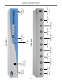
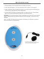
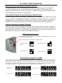
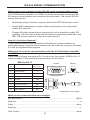
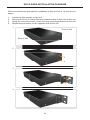
2:8
d
Distribution
Amplifier
Model # EXT-HDMI-248
USER MANUAL
www.gefen.com
ASKING FOR ASSISTANCE
Technical Support:
Telephone
Fax
(818) 772-9100
(800) 545-6900
(818) 772-9120
Technical Support Hours:
8:00 AM to 5:00 PM Monday through Friday.
Write To:
Gefen Inc.
c/o Customer Service
20600 Nordhoff Street
Chatsworth, CA 91311
www.gefen.com
[email protected]
Notice
Gefen Inc. reserves the right to make changes in the hardware, packaging
and any accompanying documentation without prior written notice.
2:8 HDMI Distribution Amplifier is a trademark of Gefen Inc.
© 2008 Gefen Inc., All Rights Reserved
TABLE OF CONTENTS
1
Introduction / Operation Notes
2
Features
3
Panel Descriptions
4
Connecting and Operating the 2:8 HDMI Distribution Amplifier
5
RMT-2 Installation
6
IR Code Configuration
7
EDID Management Feature
8
EDID Management Modes
9
RS-232 Serial Communication
10 RS-232 Serial Communication Commands
11
Rack Ears Installation Diagram
12 Wiring Diagram
13 Specifications
14 Warranty
INTRODUCTION
The Gefen 2:8 HDMI Distribution Amplifier is the perfect solution for anyone who
needs to send one or two sources of digital high definition video to multiple displays
at the same time. It supports HDMI equipment, such as DVD players, satellite set
top boxes, and HDMI displays. In operation, the digital source is connected to the
distribution amplifier’s input while eight HDMI outputs are available to be used
in part or in full. Once the unit is connected and powered, your source can be
distributed up to eight digital displays at the same time.
How It Works
Simply connect your HDMI video source to the 2:8 Distribution Amplifier’s input
using the supplied HDMI cable. Then connect up to eight HDMI displays to the unit’s
eight HDMI outputs. Once connected and powered, your source will be seen on all
eight displays at the same time. When two or more 2:8’s are connected together,
you can create a larger distribution system.
OPERATION NOTES
READ THESE NOTES BEFORE INSTALLING OR
OPERATING THE 2:8 HDMI DISTRIBUTION AMPLIFIER
•
This device supports advanced EDID management. Please see pages 7 & 8 for
complete details
•
The 2:8 HDMI Distribution Amplifier can only mirror one input video signal at a
time to all eight display outputs. The user can choose which of the two HDMI
inputs will be displayed on all eight HDMI outputs.
•
HDMI/HDCP compliant
•
Compatible with all HDMI and DVI* displays
NOTE: *When used with a DVI to HDMI adapter
1
FEATURES
Features
•
Switch easily between any two HDMI/DVI sources
•
Outputs are mirrored to eight HDMI/DVI* displays simultaneously
•
Supports resolutions up to 1080p, 2K and 1920 x 1200
•
Extends the range of HDMI compliant devices by equalizing and re-clocking the
HDMI signal
•
HDMI/HDCP compliant
Includes:
(1) 2:8 HDMI Distribution Amplifier
(1) 6’ HDMI cable (M-M)
(1) 24V DC Power Supply
(1) RMT2-IR remote
(1) Set of Rack Ears
(1) Users Manual
2
HDMI
Input 1
HDMI
Input2
Input LED
Indicator
3
Back Panel
IR Eye
IR Extension
Port
HDMI Output
HDMI Output
HDMI Output
HDMI Output
8
4
6
8
HDMI Output
HDMI Output
HDMI Output
HDMI Output
1*
3
5
7
RJ-11 To
RS-232
Serial Port
Front Panel
24V DC Power
Input
Power LED
Indicator
PANEL DESCRIPTIONS
CONNECTING THE 2:8 HDMI DISTRIBUTION AMPLIFIER
How to Connect the 2:8 HDMI Distribution Amplifier
1.
Connect the supplied cable from the HDMI source into the HDMI input port 1 of the
2:8 HDMI Distribution Amplifier.
2.
Connect a second HDMI source to HDMI input port 2 on the 2:8 HDMI Distribution
Amplifier using a user supplied HDMI cable.
3.
Connect the display(s) (up to eight) to the HDMI output port(s) of the 2:8 HDMI
Distribution Amplifier using user supplied cable(s)
4.
Plug the 24V DC power supply into the 2:8 HDMI Distribution Amplifier.
OPERATING THE 2:8 HDMI DISTRIBUTION AMPLIFIER
Switching between the inputs on the 2:8 HDMI Distribution Amplifier is done using either
the supplied RMT2-IR remote or the RJ11 to serial interface.
IR Remote
Pressing button one on the remote will select the HDMI source that is connected to
HDMI input port one. Pressing two on the remote will select the HDMI source that is
connected to HDMI input port two.
RJ11 To Serial Control Interface
Please see the diagram on page 9 for the RJ11 serial control interface pin configuration.
4
RMT2-IR INSTALLATION
1. Remove battery cover from the back of the RMT2-IR remote.
2. Verify that dip switches 1 & 2 are in the down (OFF) position. (See page 6)
3. Insert the battery, hold the battery so that you can see the positive side facing up.
The side that is not marked must be facing down.
4. Test the RMT2-IR remote by pressing ONLY one button at a time. The indicator
light on the remote will flash once each time you press a button.
WARNING: Do not press multiple buttons simultaneously and do NOT press buttons
rapidly. These actions will cause the remote to reset and steps 1-4 will have to be
repeated.
Note: The RMT2-IR ships with two batteries. One battery is required for operation,
the second battery is complimentary.
The optional IR extender allows you to
relocate your HDMI Switcher and still retain IR
control. Gefen part# EXT-RMT-EXTIR
5
IR CODE CONFIGURATION
Why would I need to change the remote channel?
In some instances, the 2:8 Distribution Amplifier for HDMI may use IR codes that
conflict with other IR remote control devices. The unit may switch inputs when
another brand IR remote control is used or the RMT-2IR may cause other brand IR
controlled devices to behave unexpectedly.
I am experiencing the issues listed above. What do I do?
In these cases it is recommended to change the IR channel that the RMT-2IR remote
control and the 2:8 Distribution Amplifier for HDMI use. The IR channel is configured
independently on the RMT-2IR remote control and the 2:8 Distribution Amplifier for
HDMI but the channel selection must match on both units for proper operation.
How Do I change the Remote Channel?
There are service DIP switches on the RMT-2IR remote control and also inside the
2:8 Distribution Amplifier for HDMI. Use the diagrams below to locate and change the
IR channel to one that is not the default. Remember that the channel must match on
both the unit and remote control for successful operation.
RMT-2IR Remote Control
Remove the battery cover on the rear side of the RMT-2IR remote control
to expose the DIP switches.
2 DIP switch bank for IR channel configuration.
Remote Channel 1:
Default
Remote Channel 2:
1
2
Remote Channel 3:
1
2
1
2
Remote Channel 4:
1
2
2:8 Distribution Amplifier for HDMI
The IR channel DIP switches for the 2:8 Distribution Amplifier for HDMI are located on an 8 bank DIP
switch inside of the unit and on its main-board. To open the unit, remove all screws on the underside and
side of the unit. Remove all HEX screws on the rear panel. This includes the screws above each HDMI
port and on each side of the RS-232 serial communications port. Carefully slide the unit apart. Locate
DIP switches 3 and 4. Once adjustments are complete replace all screws and.
Remote Channel 1:
Default
Remote Channel 2:
1 2 3 4 5 6 7 8
1 2 3 4 5 6 7 8
Remote Channel 3:
Remote Channel 4:
1 2 3 4 5 6 7 8
1 2 3 4 5 6 7 8
6
EDID MANAGEMENT FEATURE
EDID. What is it and what is it used for?
Under normal circumstances, an source device (digital and analog) will require
information about a connected device/display to assess what resolutions
and features are available. The source can then cater its output to send
only resolutions and features that are compatible with the attached device/
display. This information is called EDID (Extended Display Information Data)
and a source device can only accept and read one EDID from a connected
device/display. Likewise, the source an only output one resolution for use by a
connected device/display.
Why is EDID so important with the 2:8 Distribution Amplifier for HDMI?
The 2:8 Distribution Amplifier for HDMI is complex piece of technology that
replicates and switches between multiple inputs and outputs. Each connected
source device will require one EDID to read. EDID management is carefully
handled by 2:8 Distribution Amplifier for HDMI to provide a single EDID for each
source to read.
What options do I have to manage the EDID in the 2:8 Distribution Amplifier
for HDMI?
First, it is important to note that each source device can only output one video/
audio signal type. This includes resolutions and timings. When multiple devices/
displays are used, such as with the 2:8 Distribution Amplifier for HDMI, it is
important to use devices/displays that have similar or compatible resolutions/
features. This will ensure that the single video/audio signal produced by the
source device is accepted by all of the connected output devices/displays.
The user has the option, through a combination of DIP switch settings within the
2:8 Distribution Amplifier for HDMI, to choose how the unit will manage the EDID
from multiple HDMI devices/displays. Therefore the user has some control over
the resolutions/features that the source devices will output. The 2:8 Distribution
Amplifier for HDMI has a multiple EDID management modes that will control how
the EDID information from multiple devices/displays are combined, ignored, and
routed.
How do I change EDID modes in the 2:8 Distribution Amplifier for HDMI?
There is an bank of 8 DIP switches located on the main-baord inside of the 2:8
Distribution Amplifier for HDMI. DIP switches 1, 2, 5, and 7 are used in different
combinations to manage the EDID modes.
TIP: EDID modes and IR code channels can also be managed via the RS-232
serial communications port. For this to work, all DIP switches must be in the OFF
position. This is the factory default setting. If you wish to use this feature, please
do not open the unit. See page 9 and 10 for more information on the RS-232
serial communication features.
To access these DIP switches it will be required to open the unit. To do this,
remove all screws on the underside and side of the unit. Remove all HEX screws
on the rear panel. This includes the screws above each HDMI port and on each
side of the RS-232 serial communications port. Carefully slide the unit apart.
7
EDID MANAGEMENT MODES
EDID Modes
The diagram below illustrates the 8 DIP switch bank.
1
2
3
4
5
6
7
DIP SWITCH
Function
1
EDID Mode
2
EDID Mode
3
IR Channel
4
IR Channel
5
EDID Mode
6
N/A
7
EDID Mode
8
N/A
8
Use DIP switches 1, 2, 5, and 7 to select the desired EDID management mode.
EDID Mode 0 (Switch 1=OFF Switch2=OFF Switch5=ON)
• Edid is copied from the device connected to the first active hdmi output
port.
• All features newer that HDMI 1.2 are cleared.
EDID Mode 1 (Switch 1=ON Switch2=OFF Switch5=ON)
• Same as Mode 0 and adds basic audio support.
EDID Mode 2 (Switch 1=OFF Switch2=ON Switch5=ON)
• Same as Mode 0 and adds full audio support.
EDID Mode 3 (Switch 1=ON Switch2=ON Switch5=OFF)
• EDID is generated based on the common video and audio features of all
of the connected output devices.
EDID Mode 4 (Switch 1=OFF Switch2=ON Switch5=OFF)
• Same as Mode 3 and adds basic audio support.
EDID Mode 5 (Switch 1=ON Switch2=OFF Switch5=OFF)
• Same as Mode 3 and adds full audio support.
EDID Mode 6 (Switch 1=OFF Switch2=OFF Switch5=OFF) DEFAULT
• EDID is generated based on the common video features of all of
the connected devices and the combined audio features of all of the
connected output devices.
EDID Mode 7 (Switch 1=ON Switch2=ON Switch5=ON)
• EDID is passed unmodified from the device connected to the first
active output port.
8
RS-232 SERIAL COMMUNICATION
What features are available via the RS-232 serial communications port?
The 2:8 Distribution Amplifier for HDMI can accept commands through the RS232 serial communications port located on the rear panel. The current RS-232
control features are:
•
Switching/routing of inputs to outputs without the RMT-2IR remote control.
•
Switch EDID management modes without opening the unit to physically
modify DIP switches.
•
Change IR code channel without opening the unit to physically modify DIP
switches. (The IR code channel will still need to be manually modified on the
RMT-2IR remote control to match the code channel.)
How do I use these features?
These features were initially intended for utilization by custom installers in
automated setups. However, these features can be tested by using any Windows
PC with the Hyperterminal program.
What pins are used for communication with the 2:8 Distribution Amplifier
for HDMI?
Serial control is done through the RJ-11 port on the front panel. A DB-9 to RJ-11
cable is needed. Please see the diagram below for the pinout.
DB-9 to RJ-11
DB-9
Pin
Description
FRONT:
Connects To
RJ-11 Pin
1
Carrier Detect
N/A
2
Receive Data
3
3
Transmitted Data
2
4
Data Terminal Ready
5
Ground
6
Data Set Ready
N/A
7
Request To Send
N/A
8
Clear To Send
N/A
9
Ring Indicator
N/A
5
FRONT:
1
9
6 1
RJ-11 6-Pin
6
Female DB-9
N/A
1&6
1 6
Connectors not to scale
What are the communication port settings?
Bits per second ................................................................................................. 19200
Data bits .................................................................................................................... 8
Parity .................................................................................................................. None
Stop bits .....................................................................................................................1
Flow Control ....................................................................................................... None
9
RS-232 SERIAL COMMUNICATION COMMANDS
Switching/Routing Binary Table
ASCII
RMT2-IR
Button
1
2
1
2
Binary
0011 0001
0011 0010
EDID Management Modes
All DIP switches inside the unit must be in their default OFF position. Use the ASCII
commands below to change the EDID modes. For a description of each mode
please see page 8.
ASCII
EDID Mode
m0
0
m1
1
m2
2
m3
3
m4
4
m5
5
m6
6
m7
7
IR Remote Channel Configuration
All DIP switches inside the unit must be in their default OFF position. Use the ASCII
commands below to change the IR code channel. Please ensure that the IR remote
channel on the RMT-2IR matches any channel that is set by these commands. For a
description of the IR code channel configuration please see page 6.
ASCII
Remote Channel
r1
1
r2
2
r3
3
r4
4
10
RACK EARS INSTALLATION DIAGRAM
Rack mount ears are provided for installation of this unit into a 1U rack mount
space.
1.
2.
3.
4.
Locate the side screws on the unit.
Remove the front 2 screws that are located closest to the front of the unit.
Using the removed screws, screw the rack mounting bracket into the unit.
Repeat the procedure on the opposite side of the unit.
1
Front of unit
Rear of unit
2
3
4
11
12
HDMI cable maximum distance is 15 ft at 1080p resolution without a EXT-HDMI-141SBP or EXT-HDMI-CAT5-MS
HDMI
WIRING DIAGRAM
SPECIFICATIONS
Video Amplifier Bandwidth ............................................................................ 165 MHz
Input Video Signal ................................................................................... 1.2 Volts p-p
Input DDC Signal .............................................................................. 5 Volts p-p (TTL)
Single Link Range ........................................................................1080p / 1920 x 1200
Input Connector Type ..................................................... HDMI Type A 19 Pin Female
Output Connector Type ...................................................HDMI Type A 19 Pin Female
Remote Control Port ...................................................... RJ11 Jack For Serial Control
Power Consumption ........................................................................... 60 Watts (max.)
Power Supply .................................................................................................. 24V DC
Rack Mountable ........................................................................................... 1U Rack Space
Dimensions .............................................................................. 17”W x 1.75”H x 5.5”D
Shipping Weight .................................................................................................. 5 Lbs
13