1
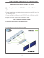
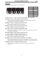
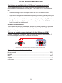
®
4x2 Switcher for
HDMI
EXT-HDMI-422
USER'S MANUAL
www.gefen.com
ASKING FOR ASSISTANCE
Technical Support:
Telephone
(818) 772-9100
(800) 545-6900
Fax
(818) 772-9120
Technical Support Hours:
8:00 AM to 5:00 PM Monday through Friday PST
Write To:
Gefen, LLC
C/O Customer Service
20600 Nordhoff St.
Chatsworth, CA 91311
www.gefen.com
[email protected]
Notice
Gefen, LLC reserves the right to make changes in the hardware, packaging and any
accompanying documentation without prior written notice.
4x2 Switcher for HDMI is a trademark of Gefen, LLC
HDMI is a trademark of hdmi.org
© 2010 Gefen, LLC, All Rights Reserved.
All trademarks are the property of their respective owners.
Rev X1
TABLE OF CONTENTS
1 Introduction
2 Features
3 Panel Descriptions
4 Connecting and Operating the 4x2 Switcher for HDMI
5 RMT-4IR Installation
6 IR Code Configuration
7 EDID Management Feature
8 EDID Management Modes
9 RS-232 Serial Communication
10 RS-232 Serial Communication Commands
11 Specifications
12 Warranty
INTRODUCTION
Congratulations on your purchase of the Gefen 4x2 Switcher for HDMI. Your complete
satisfaction is very important to us.
Gefen’s line of HDTV switches, extenders, and splitters are designed to make your A/V
equipment use more comfortable, more productive and less expensive.
The 4x2 Switcher for HDMI allows access to four HDTV devices, using two HDTV displays. Both output displays will have mirrored images. Also included is a SPDIF output
that will output the digital audio signal in audio form.
The Gefen line offers solutions for Home Theater, A/V installation, data center, information distribution, conference room presentation, school and corporate training environments.
Our Commitment
Gefen will always offer the finest quality product at the best possible price. Included in
that price is a lifetime support from a team of outstanding engineers.
The Gefen 4x2 Switcher for HDMI allows four HDTV HDMI devices to be switched
easily in to two HDTV HDMI compatible monitors or projectors. Simply connect your
HDTV displays to the Switcher’s display outputs. The 4x2 Switcher for HDMI can also
be placed at the end of a long HDMI cable to regenerate the HDMI signal.
1
FEATURES
Features
• Switches easily between any four HDMI sources
• Maintains 480i, 480p, 720p, 720i, and 1080i, 1080p resolutions
• Maintains highest HDMI single link video resolution
• Maintains highest HDMI digital audio signal
• Includes SPDIF output for easy hookup to digital audio systems
• Supports HDCP compliant devices
• HDMI or DVI to HDMI cables are used to connect the inputs and switcher output
• Inputs can be switched with the IR remote control, contact closure controller or
through the RS232 connector.
• Installs in seconds
Includes:
(1) 4x2 Switcher for HDMI
(4) 6’ HDMI cables (M-M)
(1) 5VDC Power Supply
(1) RMT-4IR
(1) Users Manual
2
HDMI
In 1
HDMI
In 2
HDMI
In 3
Indicates which
input is selected
HDMI
In 4
RS232
Controller Port
HDMI
Out 1
IR eye IR Extender
Port
HDMI
Out 2
SPDIF Out
Connects to
5VDC power
supply
Power LED
PANEL DESCRIPTIONS
3
CONNECTING AND OPERATING THE 4x2 Switcher for HDMI
How to Connect the 4x2 Switcher for HDMI to your devices
1 Connect the supplied cables from the HDTV HDMI sources into the 4x2 Switcher for
HDMI
inputs.
2 Connect the cables from your displays (monitor or projector) into the HDMI outs of the
4x2 Switcher for HDMI.
3 Connect any Digital Audio System into the SPDIF OUT of the 4x2 Switcher for HDMI
4 Plug the 5VDC power supply into the 4x2 Switcher for HDMI.
How to Control the 4x2 Switcher for HDMI
Use the RMT-4IR remote control to toggle between sources.
Connection Diagram for the 4x2 Switcher for HDMI:
4
RMT-4IR INSTALLATION
1. Remove battery cover from the back of the RMT-4IR remote.
2. Verify that dip switches 1 & 2 are in the down (OFF) position.
3. Insert the battery, hold the battery so that you can see the positive side facing up. The
side that is not marked must be facing down.
4. Test the RMT-4IR remote by pressing ONLY one button at a time. The indicator light
on the remote will flash once each time you press a button. WARNING: Do not press
multiple buttons simultaneously and do NOT press buttons rapidly. These actions will
cause the remote to reset and steps 1-4 will have to be repeated.
Note: The RMT-4IR ships with two batteries. One battery is required for operation, the
second battery is complimentary.
The optional IR extender allows you to
relocate your HDMI Switcher and still have
IR control of the HDMI Switcher
5
IR CODE CONFIGURATION
Why would I need to change the remote channel?
In some instances, the 4x2 Switcher for HDMI may use IR codes that conflict with
other IR remote control devices. The unit may switch inputs when another brand IR
remote control is used or the RMT-4IR may cause other brand IR controlled devices
to behave unexpectedly.
I am experiencing the issues listed above. What do I do?
In these cases it is recommended to change the IR channel that the RMT-4IR
remote control and the 4x2 Switcher for HDMI use. The IR channel is configured
independently on the RMT-4IR remote control and the 4x2 Switcher for HDMI but the
channel selection must match on both units for proper operation.
How Do I change the Remote Channel?
There are service DIP switches on the RMT-4IR remote control and also inside the
4x2 Switcher for HDMI. Use the diagrams below to locate and change the IR channel
to one that is not the default. Remember that the channel must match on both the
unit and remote control for successful operation.
RMT-4IR Remote Control
Remove the battery cover on the rear side of the RMT-4IR remote control
to expose the DIP switches.
2 DIP switch bank for IR channel configuration.
Remote Channel 1:
Default
Remote Channel 2:
1
2
Remote Channel 3:
1
2
1
2
Remote Channel 4:
1
2
4x2 Switcher for HDMI
The IR channel DIP switches for the 4x2 Switcher for HDMI are located on an 8 bank DIP switch inside
of the unit and on its main-board. To open the unit, remove all screws on the underside and side of the
unit. Remove all HEX screws on the rear panel. This includes the screws above each HDMI port and on
each side of the RS-232 serial communications port. Carefully slide the unit apart. Locate DIP switches 3
and 4. Once adjustments are complete replace all screws and.
Remote Channel 1:
Default
Remote Channel 2:
1 2 3 4 5 6 7 8
1 2 3 4 5 6 7 8
Remote Channel 3:
Remote Channel 4:
1 2 3 4 5 6 7 8
1 2 3 4 5 6 7 8
6
EDID MANAGEMENT FEATURE
EDID. What is it and what is it used for?
Under normal circumstances, an source device (digital and analog) will require
information about a connected device/display to assess what resolutions
and features are available. The source can then cater its output to send
only resolutions and features that are compatible with the attached device/
display. This information is called EDID (Extended Display Information Data)
and a source device can only accept and read one EDID from a connected
device/display. Likewise, the source an only output one resolution for use by a
connected device/display.
Why is EDID so important with the 4x2 Switcher for HDMI?
The 4x2 Switcher for HDMI is complex piece of technology that replicates and
switches between multiple inputs and outputs. Each connected source device
will require one EDID to read. EDID management is carefully handled by 4x2
Switcher for HDMI to provide a single EDID for each source to read.
What options do I have to manage the EDID in the 4x2 Switcher for HDMI?
First, it is important to note that each source device can only output one video/
audio signal type. This includes resolutions and timings. When multiple devices/
displays are used, such as with the 4x2 Switcher for HDMI, it is important to
use devices/displays that have similar or compatible resolutions/features. This
will ensure that the single video/audio signal produced by the source device is
accepted by all of the connected output devices/displays.
The user has the option, through a combination of DIP switch settings within
the 4x2 Switcher for HDMI, to choose how the unit will manage the EDID from
multiple HDMI devices/displays. Therefore the user has some control over the
resolutions/features that the source devices will output. The 4x2 Switcher for
HDMI has a multiple EDID management modes that will control how the EDID
information from multiple devices/displays are combined, ignored, and routed.
How do I change EDID modes in the 4x2 Switcher for HDMI?
There is an bank of 8 DIP switches located on the main-baord inside of the 4x2
Switcher for HDMI. DIP switches 1, 2, 5, and 7 are used in different combinations
to manage the EDID modes.
TIP: EDID modes and IR code channels can also be managed via the RS-232
serial communications port. For this to work, all DIP switches must be in the OFF
position. This is the factory default setting. If you wish to use this feature, please
do not open the unit. See page 9 and 10 for more information on the RS-232
serial communication features.
To access these DIP switches it will be required to open the unit. To do this,
remove all screws on the underside and side of the unit. Remove all HEX screws
on the rear panel. This includes the screws above each HDMI port and on each
side of the RS-232 serial communications port. Carefully slide the unit apart.
7
EDID MANAGEMENT MODES
v. 2015
EDID Modes
The diagram below illustrates the 8 DIP switch bank.
1
2
3
4
5
6
7
8
DIP SWITCH
Function
1
EDID Mode
2
EDID Mode
3
IR Channel
4
IR Channel
5
EDID Mode
6
N/A
7
EDID Mode
8
N/A
Use DIP switches 1, 2, 5, and 7 to select the desired EDID management mode.
EDID Mode 0 (Switch 1=OFF Switch2=OFF Switch5=ON)
• Edid is copied from the device connected to the first active hdmi output port.
• All features newer that HDMI 1.2 are cleared.
EDID Mode 1 (Switch 1=ON Switch2=OFF Switch5=ON)
• Same as Mode 0 and adds basic audio support.
EDID Mode 2 (Switch 1=OFF Switch2=ON Switch5=ON)
• Same as Mode 0 and adds full audio support.
EDID Mode 3 (Switch 1=ON Switch2=ON Switch5=OFF)
• EDID is generated based on the common video and audio features of all of the
connected output devices.
EDID Mode 4 (Switch 1=OFF Switch2=ON Switch5=OFF)
• Same as Mode 3 and adds basic audio support.
EDID Mode 5 (Switch 1=ON Switch2=OFF Switch5=OFF)
• Same as Mode 3 and adds full audio support.
EDID Mode 6 (Switch 1=OFF Switch2=OFF Switch5=OFF) DEFAULT
• EDID is generated based on the common video features of all of the connected
devices and the combined audio features of all of the connected output devices.
EDID Mode 7 (Switch 1=ON Switch2=ON Switch5=ON)
• EDID is passed unmodified from the device connected to the first active
output port.
8
RS-232 SERIAL COMMUNICATION
What features are available via the RS-232 serial communications port?
The 4x2 Switcher for HDMI can accept commands through the RS-232 serial
communications port located on the rear panel. The current RS-232 control features
are:
•
Switching/routing of inputs to outputs without the RMT-4IR remote control.
•
Switch EDID management modes without opening the unit to physically modify DIP
switches.
•
Change IR code channel without opening the unit to physically modify DIP switches.
(The IR code channel will still need to be manually modified on the RMT-4IR remote
control to match the code channel.)
How do I use these features?
These features were initially intended for utilization by custom installers in automated
setups. However, these features can be tested by using any Windows PC with the
Hyperterminal program.
What pins are used for communication with the 4x2 Switcher for HDMI?
Only pins 2 (Receive), 3 (Transmit), and 5 (Ground) are used for communication. A
null-modem adapter should not be used with this product.
12345
12345
6789
6789
Only Pins 2 (RX), 3 (TX), and 5 (Ground) are used on the RS-232 serial interface
What are the communication port settings?
Bits per second ................................................................................................. 19200
Data bits .................................................................................................................... 8
Parity .................................................................................................................. None
Stop bits .....................................................................................................................1
Flow Control ....................................................................................................... None
9
RS-232 SERIAL COMMUNICATION COMMANDS
Switching/Routing Binary Table
ASCII
1
2
3
4
RMT-4IR
Button
1
2
3
4
Binary
0011 0001
0011 0010
0011 0011
0011 0100
EDID Management Modes
All DIP switches inside the unit must be in their default OFF position. Use the ASCII
commands below to change the EDID modes. For a description of each mode please
see page 8.
ASCII
m0
m1
m2
m3
m4
m5
m6
m7
EDID Mode
0
1
2
3
4
5
6
7
IR Remote Channel Configuration
All DIP switches inside the unit must be in their default OFF position. Use the ASCII
commands below to change the IR code channel. Please ensure that the IR remote
channel on the RMT-4IR matches any channel that is set by these commands. For a
description of the IR code channel configuration please see page 6.
ASCII
r1
r2
r3
r4
Remote Channel
1
2
3
4
10
SPECIFICATIONS
Video Amplifier Bandwidth ................................................................................. 165 MHz
Input Video Signal ......................................................................................... 1.2 volts p-p
Input DDC Signal .................................................................................... 5 volts p-p (TTL)
Single Link Range ......................................................................... ...1080p / 1920 x 1200
Input Connector Type .............................................................................................. HDMI
Output Connector Type ............................................................................................HDMI
Output Audio Connector Type................................................................................ S/PDIF
Remote Control Port ......................................................................................Male RS232
Power Consumption ................................................................................ 15 Watts (max.)
Power Supply .......................................................................................................... 5VDC
Dimensions ....................................................................... 11.125”W x 1.375”H x 4.125”D
Shipping Weight ....................................................................................................... 6 Lbs
11
12
*ma-HDMI-442*
Rev X1
20600 Nordhoff St, Chatsworth CA 91311
1-800-545-6900
818-772-9100
www.gefen.com
Pb
fax: 818-772-9120
[email protected]