1
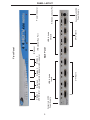
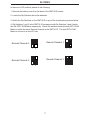
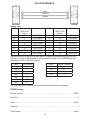
4x4 HDTV KVM
Matrix
USER
MANUAL
www.gefen.com
ASKING FOR ASSISTANCE
Technical Support:
Telephone
(818) 772-9100
(800) 545-6900
Fax
(818) 772-9120
Technical Support Hours:
8:00 AM to 5:00 PM Monday through Friday.
Write To:
Gefen Inc.
c/o Customer Service
20600 Nordhoff Street
Chatsworth CA 91311
www.gefen.com
[email protected]
Notice
Gefen Inc. reserves the right to make changes in the hardware, packaging and any
accompanying documentation without prior written notice.
The 4x4 HDTV KVM Matrix is a trademark of Gefen Inc.
© 2007 Gefen Inc., All Rights Reserved
TABLE OF CONTENTS
1
Introduction / Operation Notes
2
Features
3
Panel Layout
4
Using the 4x4 HDTV KVM Matrix
5
RMT16-IR Installation
6
Dip Switch Guidelines
7
IR Codes
8
RS-232 Interface
9
4x4 HDTV KVM Matrix Rack Mount Diagram
10
Specifications
11
Terminology
12
Warranty
INTRODUCTION
Thank you for purchasing the 4x4 HDTV KVM Matrix.
The 4x4 HDTV KVM Matrix switches four DVI sources to any four DVI displays.
Now you can easily switch four cross-platform computers to four digital displays. Our 4x4
HDTV KVM Matrix provides a simple, reliable and highly effective method of creating
multiple computer workstations, with each workstation capable of accessing any one of
the computers or sources at any time by remote control. You also have the option of
setting up the four stations locally or extending them with a Gefen extender. When used
with computers, USB and Audio Matrix control signals follow the DVI input for optimal
control. The 4x4 HDTV KVM Matrix also supports the connection of HDCP compliant
sources and displays.
Note: The switching is done by using either the RMT-16-IR remote control or through the
RS232 port. The 4x4 HDTV KVM Matrix is rack mountable. Any HDTV with HDMI
inputs can be connected to the DVI outputs of the matrix by using a DVI to HDMI adapter
if the cable used is HDMI.
OPERATION NOTES
READ THESE NOTES BEFORE INSTALLING
OR OPERATING THE 4X4 HDTV KVM MATRIX
• You should connect all the cables and power supplies prior to connecting power to the
HDTV sources and 4x4 HDTV KVM Matrix.
• When powering the sources, the display needs to point to the source input.
• The 4x4 HDTV KVM Matrix is housed in a metal box for better RF shielding.
• The 4x4 HDTV KVM Matrix works with all DVI and HDMI displays.
• The 4x4 HDTV KVM Matrix supports both AUDIO and VIDEO signals.
• The 4x4 HDTV KVM Matrix is fully HDCP compliant.
1
FEATURES
Features
• Increases your productivity by providing you with access to four computers from four
workstations
• Maintains highest resolution digital video with no loss of quality
• Supports either PC or Mac USB keyboards/mice
• USB 1.1 Matrix Switching capabilities
• Supports analog audio matrixing
• Discrete IR remote (included)
• Supports resolutions up to 1080p, 2K, and 1920 x 1200
• Supports DDWG standards for DVI monitors
• Includes rack ears
• HDCP Compliant
Includes:
(1)
(1)
(1)
(1)
(4)
(4)
(4)
(1)
4x4 HDTV KVM Matrix
RMT-16IR
24V Power Supply
5V Power Supply
6ft Audio Cables
6ft DVI Cables
6ft USB Cables
Set of Rack Ears
2
Connects to 5VDC
Power Supply
3
DVI Inputs
USB & Audio
Inputs
DVI Outputs
USB & Audio
Outputs
IR Extender Eye Port
Back Panel
Display 1
Display 4
Display 2
Display 3
LED Indicator LED Indicator LED Indicator LED Indicator
IR Sensor
Front Panel
Connects to 24VDC
Power Supply
RS232 Controller Port
Power Indicator
PANEL LAYOUT
USING THE 4X4 HDTV KVM MATRIX
1
Connect all the sources to the DVI inputs on the 4x4 HDTV KVM Matrix, using the
supplied cables.
2
Connect the HDMI/DVI displays to the outputs on the 4x4 HDTV KVM Matrix.
3
Connect the 24VDC power supply to the 4x4 HDTV KVM Matrix.
4
Connect the 5V DC power supply to the 4x4 HDTV KVM Matrix.
5
Controlling the 4x4 HDTV KVM Matrix using the RMT16-IR:
Pressing Buttons...
1-4
5-8
9-12
13-16
Switches...
Display 1 to view Source 1, 2, 3, or 4
Display 2 to view Source 1, 2, 3, or 4
Display 3 to view Source 1, 2, 3, or 4
Display 4 to view Source 1, 2, 3, or 4
*Note for computers connected to the 4x4 HDTV KVM Matrix - When your
computer boots up, it looks for an EDID (extended display identification data) from
the display to tell it what monitor is connected and what resolution to output. During
boot up of the computer you should have ONLY one output selected to one input
at a time so that the computer gets the EDID of the display that is selected. If you
have multiple outputs selected to one computer, the computer will read the EDID
of the last output selected to it. If all your displays are the same, or all displays are
capable of running at the same resolution then this step does not matter.
4
RMT16-IR INSTALLATION
1. Remove battery cover from the back of the RMT16-IR remote.
2. Verify that dip switches 1 & 2 are in the down (OFF) position.
3. Insert the battery, hold the battery so that you can see the positive side facing up. The
side that is not marked must be facing down.
4. Test the RMT16-IR remote by pressing ONLY one button at a time. The indicator light
on the remote will flash once each time you press a button. WARNING: Do not press
multiple buttons simultaneously and do NOT press buttons rapidly. These actions will
cause the remote to reset and steps 1-4 will have to be repeated.
Note: The RMT16-IR ships with two batteries. One battery is required for operation, the
second battery is complimentary.
5
DIP SWITCH GUIDELINES
DIP SWITCH
EDID GUIDE
Extended display identification data (EDID) is a data structure provided by a display to
describe its capabilities to any source that asks for it. The EDID includes manufacturer
name, product type, timings supported by the display, display size, luminance data, (for
digital displays only) pixel mapping data, supported audio channels and formats. This
information is used by the source to cater its output to resolutions and audio formats
that are supported by the display.
Additional EDID modes are available and configured using a combination of dip
switches 1, 2, and 5. Please refer below for the different EDID modes.
To access the Dip Switches, remove all screws from the bottom and sides of the
Gefen unit. Remove the hex screw heads from each side of the RS-232 and DVI ports.
Carefully slide the unit apart. The 8 Bank of Dip Switches are located on the main PCB.
Once adjustments are complete, slide the unit back together and replace all removed
screws.
EDID Mode 0 (Switch 1=OFF Switch2=OFF Switch5=ON)
-EDID is copied from the first HDMI port
EDID Mode 1 (Switch 1=ON Switch2=OFF Switch5=ON)
-Same as Mode 0 and adds basic audio support
EDID Mode 2 (Switch 1=OFF Switch2=ON Switch5=ON)
-Same as Mode 0 and adds full audio support
EDID Mode 3 (Switch 1=ON Switch2=ON Switch5=OFF)
-EDID is generated based on the common video and audio features of all of the
connected devices
EDID Mode 4 (Switch 1=OFF Switch2=ON Switch5=OFF)
-Same as Mode 3 and adds basic audio support
EDID Mode 5 (Switch 1=ON Switch2=OFF Switch5=OFF)
-Same as Mode 3 and adds full audio support
EDID Mode 6 (Switch 1=OFF Switch2=OFF Switch5=OFF) DEFAULT
-EDID is generated based on the common video features of all of the connected
devices and the combined audio features of all of the connected devices
6
IR CODES
In the event of IR conflicts, please do the following:
1. Remove the battery cover from the back of the RMT16-IR remote.
2. Locate the Dip Switches above the batteries
3. Switch the Dip Switches on the RMT16-IR to any of the combinations pictured below.
4. Dip Switches 1 and 2 in the RMT16-IR correspond with Dip Switches 3 and 4 inside
the 4x4 HDTV KVM Matrix respectively. Switch the switches inside the 4x4 HDTV KVM
Matrix to match the same Remote Channel as the RMT16-IR. The 4x4 HDTV KVM
Matrix is now set to a new IR Code.
Remote Channel 1:
Remote Channel 0:
1
2
1
2
1
2
Remote Channel 3:
Remote Channel 2:
1
2
7
RS-232 INTERFACE
Send
Transmit
Ground
Binary Table
ASCII Corresponding
RMT16-IR
Button
1
1
2
2
3
3
4
4
5
5
6
6
7
7
8
8
Hex
ASCII
0011 0001
0011 0010
0011 0011
0011 0100
0011 0101
0011 0110
0011 0111
0011 1000
9
a
b
c
d
e
f
g
Corresponding
RMT16-IR
Button
9
10
11
12
13
14
15
16
Hex
0011 1001
0110 0001
0110 0010
0110 0011
0110 0100
0110 0101
0110 0110
0110 0111
Additional control of the EDID modes and IR channel are possible using the RS-232
interface. For any of these modes to be successfully written to the EEPROM, all Dip
Switches must be in the OFF position.
ASCII
m0
m1
m2
m3
m4
m5
m6
EDID Mode
0
1
2
3
4
5
6
ASCII
r1
r2
r3
r4
Remote Channel
1
2
3
4
OK is printed out on screen when a mode has successfully been changed.
RS232 Settings
Bits per second ...................................................................................................... 19200
Data bits ......................................................................................................................... 8
Parity ....................................................................................................................... None
Stop bits ..........................................................................................................................1
Flow Control ............................................................................................................ None
8
4X4 HDTV KVM MATRIX RACK MOUNT DIAGRAM
9
SPECIFICATIONS
Video Amplifier Bandwidth..................................................................................1.65 Gbps
Input Video Signal...........................................................................................1.2 volts p-p
Input DDC Signal......................................................................................5 volts p-p (TTL)
Single Link Range................................................................................1080p/1920 x 1200
DVI Connector.................................................................DVI-I 29 pin female (digital only)
USB Input Connectors...........................................................................................Type “B”
USB Output Connectors........................................................................................Type “A”
Audio Connectors..................................................................................3.5mm mini stereo
Power Supply.........................................................................................................24V DC
Power Supply...........................................................................................................5V DC
Power Consumption....................................................................................80 watts (max)
Dimensions...................................................................................17”W x 1.75”H x 6.75”D
Rackmountable..........................................................................................1U Rack Space
Shipping Weight.......................................................................................................12 Lbs
10
TERMINOLOGY
DDC
Short form for Display Data Channel. It is a VESA standard for communication between
a monitor and a video adapter. Using DDC, a monitor can inform the video card about its
properties, such as maximum resolution and color depth. The video card can then use
this information to ensure that the user is presented with valid options for configuring the
display.
DDWG
Digital Display Working Group DDWG are the creators of the DVI specification.
DVI
Digital Visual Interface. Connection standard developed by Intel for connecting computers
to digital monitors such as flat panels and DLP projectors. A consumer electronics version,
not necessarily compatible with the PC version, is used as a connection standard for HDTV
tuners and displays. Transmits an uncompressed digital signal to the display. The latter
version uses HDCP copy protection to prevent unauthorized copying.
HDCP
High-Bandwidth Digital Content Protection. Created by Intel, HDCP is used with HDTV
signals over DVI and HDMI connections and on D-Theater D-VHS recordings to prevent
unauthorized duplication of copy written material.
HDMI
The High-Definition Multi-media Interface (HDMI) is an industry-supported, uncompressed,
all-digital audio/video interface. HDMI provides an interface between any compatible digital
audio/video source, such as a set-top box, DVD player, and A/V receiver and a compatible
digital audio and/or video monitor, such as a digital television (DTV).
HDTV
High-Definition Television. The high-resolution subset of our DTV system. The ATSC defines
HDTV as a 16:9 image with twice the horizontal and vertical resolution of our existing system,
accompanied by 5.1 channels of Dolby Digital audio. The CEA defines HDTV as an image
with 720 progressive or 1080 interlaced active (top to bottom) scan lines. 1280:720p and
1920:1080i are typically accepted as high-definition scan rates.
RS-232
Recommended Standard 232. This is the de facto standard for communication through PC
serial ports. It can refer to cables and ports that support the RS232 standard.
VESA
Video Electronic Standards Association, a consortium of manufacturers formed to establish
and maintain industry wide standards for video cards and monitors. VESA was instrumental
in the introduction of the Super VGA and Extended VGA video graphics standards with
a refresh rate of 70 Hz, minimizing flicker and helping to reduce user eyestrain and
fatigue.
11