1
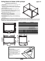
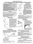
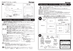
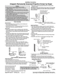
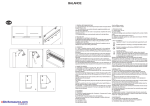
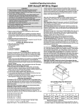
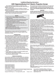
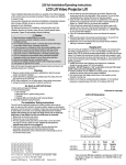
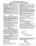
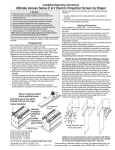
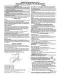
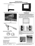
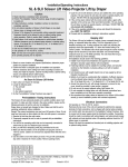
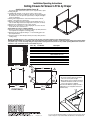
Installation/Operating Instructions
Ceiling Closure for Scissor Lift SL by Draper
Installing Optional Ceiling Closure "B"
The optional ceiling closure can be used as is, or in conjunction with, a square
of existing ceiling tile.
① If installing with ceiling tile, you may need to cut tile so that its overall
dimensions are the same as (or slightly less than) the closure panel. Place tile
into trim frame. Lay closure panel on top (back side) of ceiling tile, and tighten
screws to hold in place.
② Attach provided angle brackets to side of Bottom Panel of Scissor Lift SL.
③ Attach 5/16" threaded rods to angle bracket.
④ Run unit “up” until bottom pan stops at highest position. Mark position on 5/16"
rods even with ceiling level and cut to length (remove from pan if convenient).
⑤ Run unit “down” until bottom pan stops at “show” position.
⑥ Attach closure to lower end of 5/16" rods by slipping into four corner slots and
secure with nuts above and below slots.
Caution: Make sure nuts are completely tightened.
⑦ Run unit “up” again to highest position. Measure distance by which panel fails to
reach required “closed” height for surrounding ceiling.
⑧ Run unit “down” then re-adjust mounting of 5/16" rods in traveling grid to raise
panel required distance.
⑨ Test unit operation to confirm that panel will stop in closed position just before
touching ceiling.
Caution: DO NOT hang from, "ride" or pull down on the unit. This could create a failure and cause damage and/or injury.
PLEASE NOTE: Immediately upon completion of the surrounding ceiling, unit should be operated to confirm that optional ceiling closure panel by Draper
or by others stops 1/8" short of touching ceiling in closed position. If closure panel touches, the motor may continue operating after the lift is closed. If it
continues to cycle once the lift is closed, a motor failure may occur.
309/16"
Item Qty
①
1
②
1
③
2
④
4
⑤
8
309/16"
Part Number
C028.616.07SA
C044.194.07SA
C002.924.07SA
C077.037.49
C013.050
⑥
8
C020.082
⑦
⑧
⑨
4
4
16
C013.033
C020.152
C018.027
Description
Frame, B Closure Trim
Panel, Assembled B Closure
Bracket, B Closure Attach
Rod 3/8"-16 x 213/8" L Threaded , Zinc
Washer .375 I.D. x .875" O.D.
x .064" TK GRD 2 Zinc Flat
Screw, 10-16 X ½" 6 Lobe
Truss Head AB E-White
Washer, ¼" Flat
Screw, ¼"-20 x 5/8" Hex Head Grade 2 Zinc Cap
Nut, 3/8"-16 Zinc Hex
8 7
21 /8"
9
9
26"
3
2
4
6
1
9 5
5 9
283/16"
283/16"
FRONT/BACK
SIDE
193/16"
1
For Additional Safety:
① Be sure the nuts that attach the threaded
rods to the closure panel are tight.
② Wrap a plastic wire tie around the mounting
tab and the threaded rod at all four corners
of the closure panel (see drawing).
Please Note: Do NOT use a paper-covered or
similar wire tie—use only plastic wire ties for
maximum safety.
®
Copyright © 2011 Draper Inc. Form ScissorLift-ClosureSL_Inst11-R
Printed in U.S.A.
If you encounter any difficulties installing or servicing your Scissor Lift SL, call your
dealer or Draper, Inc. in Spiceland, Indiana, 765-987-7999, or fax 765-987-7142.
Ceiling Closure for Scissor Lift SL by Draper
page 2 of 4
Installing Optional Ceiling Closure "E"
The optional ceiling closure can be used as is, or in conjunction with, a square
of existing ceiling tile.
① If installing with ceiling tile, you may need to cut tile so that its overall
dimensions are the same as (or slightly less than) the closure panel. Place tile
into trim frame. Lay closure panel on top (back side) of ceiling tile, and tighten
screws to hold in place.
② Attach provided angle brackets to side of Bottom Panel of Scissor Lift SL.
③ Attach 5/16" threaded rods to angle bracket.
④ Run unit “up” until bottom pan stops at highest position. Mark position on 5/16"
rods even with ceiling level and cut to length (remove from pan if convenient).
⑤ Run unit “down” until bottom pan stops at “show” position.
⑥ Attach closure to lower end of 5/16" rods by slipping into four corner slots and
secure with nuts above and below slots.
Caution: Make sure nuts are completely tightened.
⑦ Run unit “up” again to highest position. Measure distance by which panel fails to
reach required “closed” height for surrounding ceiling.
⑧ Run unit “down” then re-adjust mounting of 5/16" rods in traveling grid to raise
panel required distance.
⑨ Test unit operation to confirm that panel will stop in closed position just before
touching ceiling.
Caution: DO NOT hang from, "ride" or pull down on the unit. This could create a failure and cause damage and/or injury.
PLEASE NOTE: Immediately upon completion of the surrounding ceiling, unit should be operated to confirm that optional ceiling closure panel by Draper
or by others stops 1/8" short of touching ceiling in closed position. If closure panel touches, the motor may continue operating after the lift is closed. If it
continues to cycle once the lift is closed, a motor failure may occur.
Item Qty
①
1
②
1
③
2
④
2
⑤
4
⑥
10
305/16"
4013/16"
Top View
Part Number
C044.199.07SA
C028.619.07SA
C002.920.07SA
C002.921.07SA
4 C077.037.49
C020.082
⑦
8
C013.050
⑧
⑨
⑩
⑪
⑫
16
4
4
4
4
C018.027
C020.152
C013.033
C020.321
C018.045
11
36¼" 4
Description
Panel, E Assembled Closure
Frame, E Trim
Bracket, E Front/Back Angle
Bracket, E End Angle
Rod, Threaded 3/8"-16 x 21 3/8" L Zinc
Screw, 10-16 X ½" 6 Lobe
Truss Head AB E-White
Washer .375 I.D. x .875 O.D.
x .064" TK GRD 2 Zinc Flat
Nut, 3/8"-16 Zinc Hex
Screw, ¼"-20 x 5/16" Grade 2 HH Zinc Cap
Washer, ¼", Flat
Screw, 5/16"-18 x 5/8" Grade 5 HH Zinc Cap
Nut, 5/16"-18 Zinc Hex Keps
3
25¾"
8
8
12
9 10
189/16"
5
1
6
8 7
2
387/16"
7 8
2715/16"
Side View
Front/Back View
For Additional Safety:
① Be sure the nuts that attach the threaded
rods to the closure panel are tight.
② Wrap a plastic wire tie around the mounting
tab and the threaded rod at all four corners
of the closure panel (see drawing).
Please Note: Do NOT use a paper-covered or
similar wire tie—use only plastic wire ties for
maximum safety.
www.draperinc.com
(765) 987-7999
Ceiling Closure for Scissor Lift SL by Draper
page 3 of 4
Installing Optional Ceiling Closure "SL"
The optional ceiling closure can be used as is, or in conjunction with, a square
of existing ceiling tile.
① If installing with ceiling tile, you may need to cut tile so that its overall
dimensions are the same as (or slightly less than) the closure panel. Place tile
into trim frame. Lay closure panel on top (back side) of ceiling tile, and tighten
screws to hold in place.
② Attach provided angle brackets to side of Bottom Panel of Scissor Lift SL.
③ Attach 5/16" threaded rods to angle bracket.
④ Run unit “up” until bottom pan stops at highest position. Mark position on 5/16"
rods even with ceiling level and cut to length (remove from pan if convenient).
⑤ Run unit “down” until bottom pan stops at “show” position.
⑥ Attach closure to lower end of 5/16" rods by slipping into four corner slots and
secure with nuts above and below slots.
Caution: Make sure nuts are completely tightened.
⑦ Run unit “up” again to highest position. Measure distance by which panel fails to
reach required “closed” height for surrounding ceiling.
⑧ Run unit “down” then re-adjust mounting of 5/16" rods in traveling grid to raise
panel required distance.
⑨ Test unit operation to confirm that panel will stop in closed position just before
touching ceiling.
Caution: DO NOT hang from, "ride" or pull down on the unit. This could create a failure and cause damage and/or injury.
PLEASE NOTE: Immediately upon completion of the surrounding ceiling, unit should be operated to confirm that optional ceiling closure panel by Draper
or by others stops 1/8" short of touching ceiling in closed position. If closure panel touches, the motor may continue operating after the lift is closed. If it
continues to cycle once the lift is closed, a motor failure may occur.
243/8"
Item Qty
①
4
②
1
③
1
④
4
⑤
4
⑥
16
Part Number
C013.033
C044.184.07SA
C028.573.07SA
C002.889.07SA
4 C077.052
C013.050
⑦
8
C020.082
⑧
⑨
16
4
C018.028
C020.152
Description
Washer, ¼", Flat
Panel, SL Closure
Frame, SL Closure Trim
Bracket, SL Closure Mounting
Rod, Threaded 5/16"-18 x 16" L Zinc
Washer .375 I.D. x .875 O.D.
x .064" TK GRD 2 Zinc Flat
Screw, 10-16 x ½" 6 Lobe
Truss Head AB E-White
Nut, 5/16"-18 Zinc Hex
Screw, ¼"-20 x 5/16" Grade 2 HH Zinc Cap
243/8"
Top View
1813/16"
6
6
9 1
4
8
1813/16"
8
5
195/8"
2
3
221/16"
Front/Back View
7
8 6
6 8
221/16"
Side View
www.draperinc.com
(765) 987-7999
For Additional Safety:
① Be sure the nuts that attach the threaded
rods to the closure panel are tight.
② Wrap a plastic wire tie around the mounting
tab and the threaded rod at all four corners
of the closure panel (see drawing).
Please Note: Do NOT use a paper-covered or
similar wire tie—use only plastic wire ties for
maximum safety.
Ceiling Closure for Scissor Lift SL by Draper
page 4 of 4
Installing Optional Ceiling Closure "U"
The optional ceiling closure can be used as is, or in conjunction with, a square
of existing ceiling tile.
① If installing with ceiling tile, you may need to cut tile so that its overall
dimensions are the same as (or slightly less than) the closure panel. Place tile
into trim frame. Lay closure panel on top (back side) of ceiling tile, and tighten
screws to hold in place.
② Attach provided angle brackets to side of Bottom Panel of Scissor Lift SL.
③ Attach 5/16" threaded rods to angle bracket.
④ Run unit “up” until bottom pan stops at highest position. Mark position on 5/16"
rods even with ceiling level and cut to length (remove from pan if convenient).
⑤ Run unit “down” until bottom pan stops at “show” position.
⑥ Attach closure to lower end of 5/16" rods by slipping into four corner slots and
secure with nuts above and below slots.
Caution: Make sure nuts are completely tightened.
⑦ Run unit “up” again to highest position. Measure distance by which panel fails to
reach required “closed” height for surrounding ceiling.
⑧ Run unit “down” then re-adjust mounting of 5/16" rods in traveling grid to raise
panel required distance.
⑨ Test unit operation to confirm that panel will stop in closed position just before
touching ceiling.
Caution: DO NOT hang from, "ride" or pull down on the unit. This could create a failure and cause damage and/or injury.
PLEASE NOTE: Immediately upon completion of the surrounding ceiling, unit should be operated to confirm that optional ceiling closure panel by Draper
or by others stops 1/8" short of touching ceiling in closed position. If closure panel touches, the motor may continue operating after the lift is closed. If it
continues to cycle once the lift is closed, a motor failure may occur.
Item Qty
①
1
②
1
③
2
④
2
⑤
4
⑥
8
3711/16"
3711/16"
Part Number
C028.615.07SA
C044.204.07SA
C002.923.07SA
C002.922.07SA
4 C077.037.49
C020.082
⑦
⑧
⑨
4
4
8
C020.321
C018.045
C013.050
⑩
⑪
16
4
C018.027
C020.152
⑫
4
C013.033
Description
Frame, U Closure Trim
Panel, U Assembled Closure
Bracket, U End Angle
Bracket, E Front/Back Angle
Rod, Threaded 3/8"-16 x 21 3/8" L Zinc
Screw, 10-16 X ½" 6 Lobe
Truss Head AB E-White
Screw, 5/16"-18 x 5/8" Grade 5 HH Zinc Cap
Nut, 5/16"-18 Zinc Hex Keps
Washer .375 I.D. x .875 O.D.
x .064" TK GRD 2 Zinc Flat
Nut 3/8"-16 Hex Zinc
Screw, ¼"-20 x 5/8" Hex Head
Grade 2 Zinc Cap Part 1
Washer, ¼" Flat
Top View
7
31¼"
10
3
4
27"
10
11 12
2
5
189/16"
8
10 9
6
1
351/8"
Side View
351/8" 9 10
Front/Back View
www.draperinc.com
(765) 987-7999
For Additional Safety:
① Be sure the nuts that attach the threaded
rods to the closure panel are tight.
② Wrap a plastic wire tie around the mounting
tab and the threaded rod at all four corners
of the closure panel (see drawing).
Please Note: Do NOT use a paper-covered or
similar wire tie—use only plastic wire ties for
maximum safety.