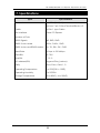
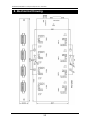
1
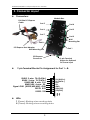
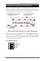
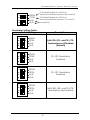
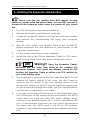
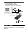
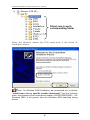
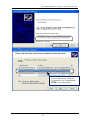
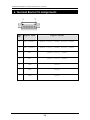
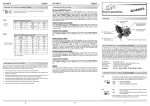
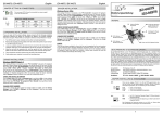
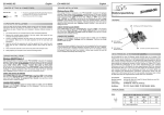
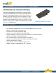
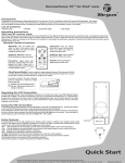
EX-47030
8S RS232/422/485 Combo PCIe Expansion Module
1. Introduction
Congratulation on your purchasing this high performance PCI Express
RS232/422/485 Combo Expansion Module Box. The product includes
an expansion module box, a PCI Express Host Adapter and a DVI-like
cable. It supports 8 serial ports which can be set in any combinations
of RS232, RS422, RS485-2W, or RS485-4W modes. Its 16C950 UART
based serial ports (128-byte deep FIFO) are fully 16C550 UART
compatible with most of the RS232C, RS422 and RS485 devices
available from the market.
Features:
Full x1 PCI Express Throughput, 250Mbytes/sec
Fully Compliant with PCI Express Base Specifications, Revision 1.1
Supports 8 RS232/422/485 Combo Serial Ports
RS232 Port Supports 3-wire Signals (TXD, RXD, GND)
Supports 4-wire RS422/485 and 2-wire RS485 Modes
Supports RS485 Auto Transceiver Turn Around by Unique Featured
ATTATM Hardware
128-byte deep FIFO per transmitter and receivers
Each Serial Port Supports 7-pin Screw-Lock-type Terminal Blocks
Supports Low Profile Form Factor with Optional Low Profile Bracket
Supports Baud Rate up to 921.6Kpbs
Optional Model: 2,500Vrms Isolated and 15KV ESD Surge Protection
Supports Win2000, XP, 2003, 2008, Vista, Win 7 and Linux
2. Packing List
Before installing this product, please make sure the following
accessories are well packed in the box:
□ Metal Expansion Module Box 1
□ Add-in PCIe Host Card x 1
□ DVI like Expansion Cable x 1
□ Driver CD × 1
□ This Installation Guide × 1
(Mark the check box to help you check it)
1
8S RS232/422/485 PCI Express Expansion Module
3. Connector Layout
Connectors:
Module Box
DVI-like PCI Express
Cable
Port 5
Port 4
Port 3
Port 6
Port 7
Port 2
Wall
Mounting Ear
Port 8
PCI Express Host Adapter
Port 1
Wall Mounting Ear
PCI Express
Connector
2-pin Terminal
Blocks for Optional
DC Power Input
7-pin Terminal Blocks Pin Assignment for Port 1 ~ 8:
RS485 2-wire: TX+(DATA+)
RS485 2-wire: TX-(DATA-)
RS422/485 4-wire: RX+
RS422/485 4-wire: RXSignal GND (RS232/422/485): GND
RS232: RXD
RS232: TXD
TX+(DATA+)
TX-(DATA-)
RX+
RXGND
RXD(232)
TXD(232)
R T
LEDs:
T (Green): Blinking when sending data
R (Green): Blinking when receiving data
2
8S RS232/422/485 PCI Express Expansion Module
4. Mode and Terminator Setting Switches
There are 16 4-pin DIP switches on the back side of the box for Port 1
to Port 8. 8 of them are mode switches (marked M1 to M8 for Port 1 to
Port 8 respectively) and the other 8 are terminator configuration
switches (marked T1 to T8 for Port 1 to Port 8 respectively).
Terminator Setting Switches
( T1~T8 for Port 1~8 )
RS232, 422, 485 Mode Switches
( M1~M8 for Port 1~8 )
(Bottom View)
1. Mode Switches (M1 to M8 for Port 1 to Port 8 respectively):
Each M1 to M8 has 4 switch pins which were marked their function
names as the following diagram. Pin 1 is to enable RS485 2 wire mode
(when ON), pin 2 enables RS485 4 wire mode (ON), pin 3 enables
RS422 mode (ON) and pin 4 enables Echo option (ON). Please refer to
the following table for more detail.
M1 to M8 DIP Switches:
ON
1 2 3 4
RS485-2W
RS485-4W
RS422
ECHO
3
8S RS232/422/485 PCI Express Expansion Module
Mode Setting Table:
Switch Settings
Description
ON
1 2 3 4
RS485-2W
RS485-4W
RS422
ECHO
RS485 2-wire mode
(Default)
ON
1 2 3 4
RS485-2W
RS485-4W
RS422
ECHO
RS485 4-wire mode
ON
1 2 3 4
RS485-2W
RS485-4W
RS422
ECHO
RS422 mode
ON
1 2 3 4
Echo mode enabled
(Note: Only applicable for
RS485-2W mode)
RS485-2W
RS485-4W
RS422
ECHO
2. Terminator Switches (T1 to T8 for Port 1 to Port 8
respectively):
The design of each RS485 and RS422 port has built-in 2 120 Ohm
termination resistors. One is in between RX+ and RX-, controlled by DIP
switch pin 1; another is in between TX+ and TX-, controlled by DIP
switch pin 2. When the switch pin is set ON, the corresponding
terminator resistor is enabled, otherwise it is disabled (floated). Both
switch pins were set to OFF by the factory default settings.
T1 to T8 DIP Switches:
4
8S RS232/422/485 PCI Express Expansion Module
ON
1 2 3 4
RXTM
TXTM
N/A
N/A
To Enable/Disable the 120 Ohm
Termination Resistor between RX+ and RXTo Enable/Disable the 120 Ohm
Termination Resistor between TX+ and TXUnused Pins
Terminator Setting Table:
Switch Settings
Description
ON
1 2 3 4
RXTM
TXTM
N/A
N/A
Both RX+/RX- and TX+/TXTerminators are Disabled
(Default)
ON
1 2 3 4
ON
1 2 3 4
ON
1 2 3 4
RXTM
TXTM
N/A
N/A
TX+/TX- Terminator
Enabled
RXTM
TXTM
N/A
N/A
TX+/TX- Terminator
Enabled
RXTM
TXTM
N/A
N/A
Both RX+/RX- and TX+/TXTerminators are Enabled
5
8S RS232/422/485 PCI Express Expansion Module
5. Installing the Expansion Module Box
Please note that this product does NOT support hot-plug
feature by means of the Expansion Cable. You can NOT connect or
disconnect the expansion cable unless you power off your system
first.
1.
Turn OFF the system power before installation!
2.
Remove the chassis cover from your computer
3.
Locate an unused PCI Express slot (typically white and smaller)
and remove the corresponding slot cover from computer
chassis.
4.
Plug the PCIe add-in Host Adapter Card to the unused PCI
Express expansion slot and attached its card bracket to the
computer chassis screw.
5.
Put the chassis cover back on the computer.
6.
Install one end of the DVI-like Expansion Cable to PCIe add-in
card’s connector and the other end to the Expansion Box’s.
DVI
Waring!! Since the Expansion Cable’s
connector has the same form factor as the standard DVI
connector, however, their signals are different, please do NOT
connect the Expansion Cable to neither your LCD monitor nor
your Video Graphic cards.
7.
The Module Box is powered by the DVI cable from the PCIe Host
Adapter by factory default. In this case, you don’t have to
connect any DC power to the 2-pin terminal blocks on the
Module Box. Unless your host PC cannot support enough power
for the Module Box through the cable, the 2-pin terminal blocks
must be left unconnected in most cases.
8.
If you are connecting a RS232 device to the Module Box, then
the 3 RS232 pins on the terminal blocks are required. The RS232
mode does not need any extra DIP switch settings, simply
connect to the terminal blocks’ pin 5, 6 and 7 and left the rest
pin 1~4 unconnected. Each port can only work in one mode at
the same time. The RS232 mode is not set by DIP switches.
Instead, it is automatically supported by the separate connector
pins.
6
8S RS232/422/485 PCI Express Expansion Module
9.
Turn ON the power of the PC system.
10. Proceed with Software Driver Installation.
11. The connection is explained as the following diagram:
PCIe Host Card in the PC
System
Expansion Cable
Expansion Module Box
2-pin Terminal
Blocks
6. Software Installation
The drivers of the RS232/422/485 Combo PCIe Module Box for each
Operating System were shipped in the following different folders on
the driver CD:
7
8S RS232/422/485 PCI Express Expansion Module
Drivers are in each
corresponding folder
When the Windows detect the PCIe serial ports, it will invoke its
Installation Wizard:
Note: For Windows 2000 installation, we recommend you to choose
“Install from a list or specific location (Advanced)” from the following
menu, then browse to the correct driver location (\IO\OXFORD2\2000\...) for
Windows 2000. It will prevent from the Windows 2000 searching wrong
drivers.
8
8S RS232/422/485 PCI Express Expansion Module
Check Windows Version
Showed in the folder here:
XP32 in this example
9
8S RS232/422/485 PCI Express Expansion Module
6. Terminal Blocks Pin Assignments
1
7
Pin
No.
Signal Name
Support Modes
1
TX+ (DATA+)
RS485 2-wire, RS485 4-wire, RS422
2
TX- (DATA-)
RS485 2-wire, RS485 4-wire, RS422
3
RX+
RS485 4-wire, RS422
4
RX-
RS485 4-wire, RS422
5
GND
RS485 2-wire, RS485 4-wire, RS422 and
RS232
6
RXD
RS232
7
TXD
RS232
10
8S RS232/422/485 PCI Express Expansion Module
7. Specifications
Type
Connectors
Specifications
Host: DVI (24+5 pin)
Devices: 7-pin 3.5mm Terminal Blocks x 8
Cable
DVI 24+1 type Cable
Bus Interface
1-lane PCI Express
Number of Ports
8
RS232 Signals
TXD, RXD, GND
RS485 2-wire mode
DATA+, DATA-, GND
RS485 4-wire and RS422 modes
TX+, TX-, RX+, RX-, GND
Baud Rate
110 bps to 921.6Kbps
Data Bits
5,6,7,8,9
Stop Bits
1, 1.5, 2
I/O address/IRQ
Plug-and-Play (various)
Parity
None, Even, Odd, 1, 0
Operating Temperature
0 to 55°C(32 to 132°F)
Operating Humidity
5 to 95% RH
Storage Temperature
-20 to 85°C (-4 to 185°F)
11
8S RS232/422/485 PCI Express Expansion Module
8. Mechanical Drawing
12