1
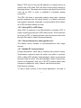
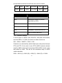
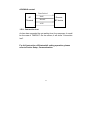
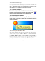
Copyright © 2010.
All rights reserved.
No warranty of any kind is made in regard to this material,
including, but not limited to, implied warranties of merchantability
or fitness for a particular purpose. Although every effort is made to
assure accuracy and completeness, we can not be held liable for
any errors contained herein nor incidental or consequential
damages in connection with furnishing, performance or use of this
material.
We shall be under no liability in respect of any defect arising from
fair wear and tear, willful damage, negligence, abnormal working
conditions, failure to follow the instructions and warnings, or
misuse or alteration or repair of the products without written
approval.
No part of this document may be reproduced, transmitted, stored
in a retrieval system, transcribed, or translated into any language
or computer language in any form or by any means electronic,
mechanical, magnetic, optical, chemical, manual or otherwise,
without express written consent and authorization.
We reserve the right to make changes in product design without
reservation and without notification. The material in this guide is
for information only and is subject to change without notice.
All trademarks mentioned herein, registered or otherwise, are the
properties of their various respective owners.
ii
Laser Safety
The portable data terminal complies with safety standard IEC
60825 for a Class I laser product. It also complies with CDRH as
applicable to a Class II laser product. Avoid long term staring into
direct laser light.
Radiant Energy: The advanced portable data terminal uses two
low-power visible laser diodes operating at 650nm in an
opto-mechanical scanner resulting in less than 3.9µW radiated
power as observed through a 7mm aperture and averaged over
10 seconds.
Do not attempt to remove the protective housing of the scanner,
as un-scanned laser light with a peak output up to 0.8mW would
be accessible inside.
Laser Light Viewing: The scan window is the only aperture
through which laser light may be observed from this product. A
failure of the scanner motor, while the laser diode continues to
emit a laser beam, may cause emission levels to exceed those for
safe operation. The scanner has safeguards to prevent this
occurrence. If, however, a stationary laser beam is emitted, the
failing scanner should be disconnected from its power source
immediately.
Adjustments: Do not attempt any adjustments or alteration of this
product. Do not remove the protective housing of the scanner.
There are no user-serviceable parts inside.
Caution: Use of controls or adjustments or performance of
procedures other than those specified herein may result in
hazardous laser light exposure.
Optical: The use of optical instruments with this product will
increase the eye hazard. Optical instruments include binoculars,
magnifying glasses, and microscopes but do not include normal
eye glasses worn by the user.
iii
Table of Content
General Information ...................................................................1
Introduction............................................................................ 1
Unpacking .............................................................................. 2
Device Outline........................................................................ 3
Battery Care ........................................................................... 4
Bluetooth® Communication ................................................. 6
Use Bluetooth® Dongle....................................................... 10
Getting Start............................................................................. 14
Installing and charging battery........................................... 14
Power on device to collect data ......................................... 16
Scan barcode ....................................................................... 18
Key in data............................................................................ 19
Upload Data.......................................................................... 21
Upload data with Windows Software ................................. 21
Delete Data ........................................................................... 21
Power off device .................................................................. 21
Device Setup............................................................................ 22
LCD Contrast........................................................................ 22
Beep Volume ........................................................................ 22
System Clock ....................................................................... 22
Barcode Setup ..................................................................... 23
Communication.................................................................... 23
Auto Power off ..................................................................... 28
Default Parameter ................................................................ 28
User Reset ............................................................................... 30
iv
General Information
1.1. Introduction
Congratulations on your purchase of the Bluetooth Personal Data
Collector (PDC) with LCD display. Along with superior portability
and visually safe scanning Engine which include CCD and Laser
two types, the PDC features a real-time clock, a buzzer, a
dual-color status LED, also an UART port with optional Bluetooth
or various communication cable for connection to external
equipment.
The on-board 64K EEPROM provides a robust, stable memory
space dedicated to storing scanned data. The PDC can retain
more than 2000 records construct by an UPC code with
timestamp.
The Personal Data Collector comes with a built-in basic data
collection firmware, called FREETASK that can scan and store
barcodes, and do simple edits on the stored data. Data can be
uploaded to a PC through the Bluetooth or RS-232 / USB cable.
WinTaskGen, a software program on the included CD-ROM, can
be used to create customized programs (Tasks) for download and
use with the PDC. A Task can have up to four operation
procedures to manage four data forms each with 16 separate data
fields.
For more advanced requirements, there are available libraries for
developing programs under the Keil C environment. Contact your
agent if you are interested in this approach.
1
1.2. Unpacking
The PDC package should contain:
- 1 ea. Pocket-Sized Personal Data Collector
- 1 ea. DB-9(F) serial communication cable
( For data upload and download)
- 3 ea. AAA NiMH rechargeable batteries
- 1 ea Power Adapter
If any package contents are damaged or missing, please contact
your dealer immediately.
Optional Accessory
- Bluetooth USB Dongle
- USB-232 or USB-HID cable
( To transfer data from PDC to a PC)
2
1.3. Device Outline
LCD
Up Key
LED
Down
Function
Scan
UART port
Figure 1: Pocket-Sized Personal Data Collector
3
1.4. Battery Care
In the interests of providing the best product performance possible,
the Personal Data Collector comes with high quality, rechargeable
Nickel Metal Hydride (NiMH) batteries and a Power Adapter. After
NiMH batteries are installed, connect the Power Adapter cable
and the batteries charge right in the unit.
Before you use new Personal Data Collector and new NiMH
batteries for the first time you should charge them fully at
least 6 hours. Please note that new NiMH batteries need to go
through three to five charge-dis-charge cycles before they reach
peak performance and capacity. For the first few times that you
use new NiMH batteries, you may find that they discharge fairly
quickly during use. This is normal until the batteries mature.
It is highly recommended that NiMH batteries always be operated
until fully discharged before recharging. If you recharge NiMH
batteries before they are fully discharged, they may develop a
pattern of inhibited output.
Under favorable conditions, NiMH batteries can last through
hundreds of recharges. You will get better performance if you
keep battery teams together. Don’t mix new and old batteries.
Note:
1. If the PDC will remain unused for an extended period (two
months or more) the batteries should be removed. Even when the
PDC is turned off, there is a very small amount of power
consumed, which can, over time, have a bad effect on batteries.
2. At the first time using Personal Data Collector after NiMH
4
batteries already loaded, please press and hold both v and ^ keys
for 30 sec. to turn on the PDC
3. 3 pcs AAA 700mAH NiMH rechargeable batteries (Use ZEBEX
supplied rechargeable batteries only)
5
1.5. Bluetooth® Communication
The PDC supports to connect with a Bluetooth® radio device via
Serial Protocol Profile (SPP). It works like virtual serial cable once
connection pair between two devices is established.
Please make sure the Bluetooth® function is finely equipped on
the host device, as well as an application program is installed. If
an optional Bluetooth USB dongle is purchased, please refer to a
separate product manual in CD for IVT software instruction. For
further enquiries, please contact your dealer.
1.5.1. Connection Mode:
Before establish a Bluetooth® connection between two devices, it
is necessary to define which device to be the “Master” during the
communication. The “Master” device holds the initiative to
connect or disconnect the “Slave” device. The “Slave” device
waits for the command from “Master” when it’s power on.
1.5.2. Bluetooth Device Address:
Each Bluetooth® device has a unique hex number with 12 digits
to identify itself during communication, as so called Bluetooth
Device (BD) address. It is essential to set up a target BD address
before making a pairing of SPP connection.
1.5.3. Personal Identify Number code:
A Personal Identify Number (PIN) code is used as a validation
password.
1.5.4. Pairing PDC as SPP Master:
When a pairing process is initiated by PDC, PDC is known as SPP
6
Master. PDC has to know the BD address of a target device as
well as sets a PIN code. PDC will send out the paring request to
the target device. The target device has to reply by the correct PIN
code set by PDC in order to establish a successful pairing
connection.
The PDC will show a successful pairing status after receiving
positive response from the target device, or a failed connection
with negative response. Otherwise, a timeout status will be shown
as if PDC has been waiting too long.
1.5.5. Pairing PDC as SPP Slave:
When PDC is powered on and Bluetooth® is activated, PDC is
ready for pairing process as a SPP Slave device. A PIN code has
to be set in PDC. At pairing process, the host device shall enter
the right PIN code to make a successful pairing.
1.5.6. Connect/disconnect with target devices:
The Master device decides to connect/disconnect with target
devices.
1.5.7. Reliable RF communication:
During transmission, each data is featured with protocol coding.
Transmission response would be made once data is received,
ACK or NAK. ACK indicates “acknowledged”, data is received and
decoded. NAK is meant “non-acknowledged” data is received but
cannot be recognized. Also use a STX/ETX packed and/or data
checksum is helped for verify if data is valid at receive host.
Data Format of packet
To send a data (record) to the remote application, the data is
7
encapsulated as below format if the item is set to enable:
STX
SEQ
Data
Terminator
CKS
ETX
1 Byte
1 Byte
Varies
1 or 2 Byte
1 Byte
1 Byte
Title
Definition
STX
Start of packed data 02H
SEQ
Sequential number of packed,
Use 020H to 07FH
DATA
Record data
Terminator
Data terminator
CKS
Checksum, Use 020H to 07FH
ETX
End of packed data 03H
1.5.8. Packed Example:
If record data is "ABCD" with STX/ETX, SEQ and CKS enable,
assume SEQ is ‘0’ (030H) the send out data is format as:
02H + 030H + "ABCD "+ 03AH + 03H
Checksum is calculated by add all data byte in the packed except
STX and ETX. If the result is over 07FH (ASCII extend) subtract
result by 080H, if the result is less than 020H (ASCII control code)
add result by 020H. This will let the checksum keep in ASCII
visible character.
030H + 041H (A) + 042H (B) + 043H (C) + 044H (D) = 013AH
8
ACK/NAK control:
Data Packed
BT
Terminal
NAK
Remote
BT device
Resend
ACK
1.5.9. Connection lost:
As time has exceeded the set waiting time for a response, it would
be the case of TIMEOUT. On the screen, it will show “Connection
lost”.
For full instruction of Bluetooth® setting operation, please
refer to Device Setup, Communication.
9
1.6.Use Bluetooth® Dongle
If an optional Bluetooth USB dongle is purchased with PDC, find
the IVT BlueSoleil software in CD packed with the dongle. Or visit
the website of IVT company to download trial version.
1.6.1. Software installation:
Execute the setup.exe file and follow the instructions of
software. Plug the dongle into USB port, the dongle should
detect by system and Bluetooth icon will became blue.
1.6.2. Bluetooth Device Address:
Double click the Bluetooth icon to open BlueSoleil main window.
Hover mouse on red ball to display the local Bluetooth device's
name and address.
1.6.3. Pairing with SPP Master PDC:
Set dongle address with PIN code to PDC then start pairing.
(Refer to the description “PDC as Master” of “Communication”
of “device Setup” section of this manual.) While pairing a
Bluetooth passkey window will pop out. Type the PIN code as
passkey to enable remote connection pair. See below picture.
10
A Bluetooth service Authorization window will pop out. Set always
allow the device access to enable and click “Yes”.
After pairing the PDC try to connect to PC. The connect massage
appear at right corner to indicate COM port number to connect.
Set the COMM port number to the software you used.
The PDC can start communication with PC by “WinTaskGen”
software or “Upload” mode. Please refer to section “Use
Windows Task Generator” and “Upload Data”
11
1.6.4. Pairing and connect to a SPP Slave PDC:
To pairing and connect a SPP slave PDC, the slave mode and PIN
code must set before operation. Power on the PDC and press FN
to show “Remote Screen”, follow by press ^ to start connect. The
PDC is waiting for master dongle operation.
Single-click red ball in main window of BlueSoleil. PC start inquiry
devices within radio range. All found devices icon will appear in
main window.
Right click the PDC icon to enable device service list, select “Pair
Device” to start pairing operation.
Bluetooth passkey window will pop out. Type the PIN code as
passkey to finish pair. Same as picture at page 10.
Right click PDC icon and select connect to “Bluetooth Serial Port
Service.
12
A “Quick Connect” window pop out after success connect.
Use PC software to connect with PDC, set the COMM port show
in “Quick Connect” window. Right click device icon and select
“status” can find connected COM port number too.
13
Getting Start
2.1. Installing and charging battery
Battery Cover Lock
Figure 2: Inserting Batteries
Press the battery cover lock to remove the cover.
Insert batteries according to the orientation in the picture
Replace the cover and lock it back.
Charging Batteries
Warning!
Use the Power Adapter with NiMH batteries ONLY!
Connecting the Power Adapter with any other type of batteries in
the PDC voids the warranty, ruins batteries, can burn up the
Personal Data Collector, and could possibly cause harm to
persons or property! You may use regular disposable alkaline
cells to operate the PDC, but never mix NiMH with alkaline
batteries, and never connect the Power Adapter when there are
disposable (alkaline) batteries in the unit.
To charge NiMH batteries:
1. With NiMH rechargeable batteries (ONLY!) in the PDC unit,
connect PDC with the Communication Cable.
14
2. Plug the Power Adapter connector into the socket on the side of
the large end connector of the Communication Cable.
3. Plug the Power Adapter into an outlet. While charging, the LED
on the PDC lights up red. The LED turns off when the batteries
are fully charged. Charging takes 3 to 5 hours.
Figure 3: Connecting the Power Adapter
It is normal that the Power Adapter and the NiMH battery cells
become warm during charging.
Note:
If needed, when NiMH batteries are low, the PDC may be
operated with the Power Adapter connected. Never use the
Power Adapter with other types of batteries inside the PDC unit!
15
2.2. Power on device to collect data
The Personal Data Collector is pre-programmed with a basic data
collection program, FREETASK that can read and store barcodes,
do simple edits, and upload data to a PC through the
Communication Cable.
2.2.1. Power on device
Press and hold the v and ^ keys together to turn on the Personal
Data Collector, then the screen will direct jump to Power-on scan
screen.
Figure 4: Power-on Scan Screen
Press the FN key to Remote Screen.
Figure 5: Remote Screen
Then, press SCAN to the Main Menu.
Figure 6: Main Menu
16
2.2.2. Menu operation
The menu items show on LCD and a reverse item indicates
current selection. Use ^ and v keys to change the item selection
and confirm by pressing SCAN key.
Menu tree list
1. Run Task
2. Delete Data
3. Setup
1. LCD Contrast
2. Beep Volume
3. System Clock
4. Barcode Set
5. Communication
6. Auto Power Off
4. Upload Data
Select the Run Task under Main Menu. The LCD shows <Rec>,
for record number, and is ready to scan and collect data.
Figure 7: FREETASK screen
17
2.3. Scan barcode
Select 1.Run Task Enter into data input Press SCAN key to
under Main menu
mode.
scan barcode.
Hold PDC to point at the targeted barcode. Sweep the red light
vertically across the barcode
correct
wrong
If decode success, Hold SCAN key will Release to revert to
a short beep emit *, keep scanned data “input mode” ready
LED flashes green display on LCD
for the next scan
* Only if Beep Volume is activated. Please refer to Device Setup,
Beep Volume.
18
2.4. Key in data
When requiring to key in data manually, there are two modes of
data entry.
Mode One:
Press ^ key once Cursor digit add by Press v to move
start edit numeric
one each ^ key
cursor right 1 digit
Empty digit cause
cursor back to start
Press Scan key to Press FN to give up
confirm input data
and back to “input”
Mode Two:
Press and hold ^
key to run numbers
Release to stop
Press ^ keys to
increase data
Press v keys to Press Scan key to Press FN to go
decrease data
confirm input data
mode one
19
Data storage
The PDC can retain more than 2,000 records. To review stored
data, press the ^ key.
To end review of stored data, press the FN key.
To exit scanning mode, press the FN key.
To view scanned data:
Press v key in input Use ^ key move to Use v keys move to
mode to start view
previous record
next record
Use Scan + ^ key Use Scan + v key Press FN key to
edit field data, FN for 2 seconds to exit to input mode
to exit
delete record data
Record 10 deleted
20
2.5. Upload Data
There are three kinds of interface to upload data, Bluetooth®,
RS-232 and HID. Once a communication device is set up (please
refer to Device Setup, Communication), PDC will automatically
detect its readiness before starting uploading data.
Figure 8: Upload Data
2.6. Upload data with Windows Software
You can also upload data by specified PC software, please refer
to section Use WinTaskGen.
2.7. Delete Data
Use v and ^ keys to commend “Y” (yes) or “N” (no) to delete data.
Follow by SCAN key to confirm.
Figure 9: Delete Data
2.8. Power off device
To turn off the Personal Data Collector, press and hold FN at
Remote Screen. The screen goes blank; data is retained.
21
Device Setup
Select 3.Setup under Main Menu to enter Setup sub-menu.
3.1. LCD Contrast
Use v and ^ keys to adjust LCD contrast from 1 to 22. Follow by
SCAN to confirm.
Figure 10: LCD Contrast
3.2. Beep Volume
Use v and ^ keys to select Volume from Low, Medium, Loud and
Quiet. Follow by SCAN to confirm.
Figure 11: Beep Volume
3.3. System Clock
Set Date
Set Time
Use ^ and v key
22
3.4. Barcode Setup
Use SCAN key to confirm setting and to go through different types
of barcode, EAN/UPC, Code 39, Codabar, ITF 25, Code 128,
Code 93, RSS14, RSS14 Expanded, RSS14 Limited. Press v and
^ keys to select On/Off.
Figure 12: Barcode Setup
3.5. Communication
3.5.1.Select communication device
There are three kinds of interface for communication, Bluetooth®,
RS-232 and HID. The Bluetooth® include master and slave mode
SPP profile is simulate a wired RS232 interface, the USB-HID is
same as USB keyboard can easy adapt to any host computer like
a standard keyboard.
3.5.2.RF Device – PDC as Master
Select RF Device
Select 1. Master Previously paired
Mode
BD is shown.
23
Modify existing BD:
Press ^ key to ^:
Hexadecimal
modify BD at Edit character
mode.
v: move cursor
FN: undo all
SCAN: confirm
Press SCAN to
confirm again, or v,
^ or FN to edit
mode.
Enter new BD:
Press v key to clear ^: Hexadecimal
existing BD at Edit v: move cursor
mode.
FN: undo all
SCAN: confirm
Press SCAN to
confirm again, or v,
^ or FN to edit
mode.
SCAN new BD:
Press SCAN key to Point at a targeted Press SCAN
enter
scanning barcode and press confirm
mode
SCAN
24
to
Set PIN code:
Previously paired PIN is Same as setting BD. ^ key to
shown. Press v, ^ or FN and modify existing PIN. v key to
enter to edit mode.
clear existing PIN. SCAN key
for scanning a new PIN.
Follow by SCAN to confirm.
Pairing to slave device:
BD and PIN are
shown. Press
SCAN to confirm.
Press SCAN to
start pairing or FN
to exit.
Starting pairing to
slave device
Pairing fail
Pairing Success
Try connect
Connect to slave
Success
After success pairing to slave device and establish connection
once, the PDC finish pair operation. The left communication
parameter is same as RS-232 setting.
25
3.5.3. RF Device – PDC as Slave
Select RF Device
Select 2. Slave
Mode
Previously PIN is
shown.
The left communication parameter is same as RS-232 setting.
3.5.4. RS-232 Cable
Select RS-232
Cable
Disable/Enable
Sequential Num.
Press SCAN to
select
Disable/Enable
Checksum Digit.
Press SCAN to
select
Disable/Enable
STX/ETX Packet.
Press SCAN to
select
If enable STX/ETX
you will asked set
Add Terminator.
Select Data
Terminator. Press
SCAN to confirm
26
Disable/Enable
Xon/Xoff Control.
Press SCAN to
select
Dis/Enable Host
ACK/NAK. Press
SCAN to select
Dis/Enable Online
Send Rec. Press
SCAN to select
Disable/Enable
Offline Operate.
Press SCAN to
select
Set Host
Response time.
Press SCAN to
select
3.5.5. USB HID Cable
Select USB HID
Cable
Set HID Language.
Press SCAN to
select
Set Delay Setup.
^: numbers and
letters
v: move cursor
FN: undo
SCAN: confirm
Set Data
Terminator. Press
SCAN to select
Disable/Enable
Online Send Rec.
Press SCAN to
select
Disable/Enable
Offline Operate.
Press SCAN to
select
27
3.6. Auto Power off
Use v and ^ keys to select the wait time of Auto Power off. Select
to the setting of 1, 3, 5, 10, 30 minutes or Disable. Follow by
SCAN key to confirm.
Figure 13: Auto Power Off
3.7. Default Parameter
The default settings will be restored whenever performing “User
reset” operation, the “Comm. Device” parameter will not be
changed by reset operation and the parameter tables are different
according to different communication devices.
Parameter
Default
Basic parameter
LCD Contrast
8
Beep Volume
Loud
Auto Power OFF
5 min.
Barcode Set
EAN/UPC
Enable
CODE 39
Enable
28
Codabar
Enable
ITF 25
Enable
Code 128
Enable
Code 93
Enable
MSI Code
Enable
RSS14
Disable
RSS14 Expanded
Disable
RSS14 Limited
Disable
Communication
RF Device
Communication Mode
Master
Sequential Num.
Disable
Checksum Digit
Disable
STX/ETX Packet
Disable
Send Terminator
Disable (STX/ETX on only)
Data Terminator
CR/LF
Host ACK/NAK
Enable
Host Response
Online Send Rec.
Offline Operate
300 mS (ACK/NAK on
only)
Disable
Disable (Online enable
only)
RS-232 Cable
Sequential Num.
Disable
Checksum Digit
Disable
STX/ETX Packet
Disable
Add Terminator
Disable (STX/ETX on only)
29
Data Terminator
CR/LF
Host ACK/NAK
Enable
Host Response
Online Send Rec.
Offline Operate
300 mS (ACK/NAK on
only)
Disable
Disable (Online enable
only)
USB-HID Cable
HID Language
USA
Delay Setup
50 mS
Data Terminator
CR
Online Send Rec.
Disable
Offline Operate
Disable (Online enable
only)
User Reset
While PDC is powered off, press and hold SCAN key for more
than 1.5 Sec. As soon as the green LED Lit-up, press FN key.
Then, the user reset screen will appear. Press SCAN key to
confirm reset.
30