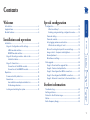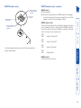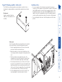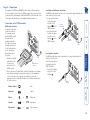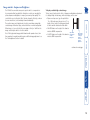
1
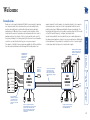
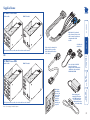
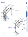
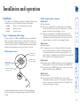
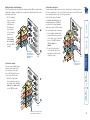
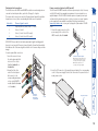
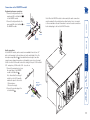
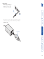
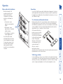
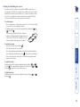
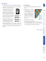
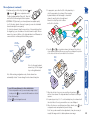
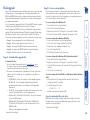
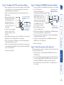
AdderLink X2 Multi Screen Remote Extenders N EE R ISC LT MU AL C LO VID EO IN EO m 4 VID EO IN EO VID EO VID OU EO VID EO 2 EO T3 EO CP U/K VM OU T2 VID EO EO OU OU T2 VID d w.a ww T3 VID OU m .co der OU T4 T4 3 VID OU T o er.c add . ww VID IN LT MU TE MO RE w VID N EE R ISC OU T1 OU T1 SW ITC H/ VID EO Further information Troubleshooting ........................................................................26 Getting assistance......................................................................27 Products in the X2-Series range................................................28 Cables .........................................................................................28 Radio Frequency Energy ...........................................................29 Installation ...................................................................................5 Stage A - Configuration switch settings ................................5 LOCAL module switches.....................................................5 REMOTE module switches .................................................6 Stage B - Mounting a module – desk or rack ........................7 Installation Advice..............................................................7 Stage C - Connections.............................................................8 Connections at the LOCAL module ...................................8 Connections at the REMOTE module..............................11 Operation...................................................................................14 Power and activity indicators...............................................14 General use ...........................................................................14 User arbitration and keyboard indicators ......................14 Visible image shadows .....................................................14 Locking and unlocking the system ......................................15 Installation and operation Configuration ............................................................................16 What are hotkeys? ...........................................................16 Entering, using and exiting configuration mode...........16 Password setting ...................................................................17 Password override.................................................................17 Hot plugging and mouse restoration ..................................18 Which restore setting do I use?.......................................18 Microsoft and Logitech -specific mouse settings ................18 Image controls - sharpness and brightness .........................19 Skew adjustment ..................................................................21 Miscellaneous settings..........................................................23 Flash upgrade ............................................................................24 Stage A - Download the upgrade files ................................24 Stage B - Create a startup diskette ......................................24 Stage C - Reconfigure the LOCAL connections ...................25 Stage D - Reconfigure the REMOTE connections................25 Stage E - Return all connections to their usual states ........25 Introduction .................................................................................2 Supplied items .............................................................................3 Module features ..........................................................................4 Special configuration Welcome Contents 1 Welcome 3 LOCAL Power supply unit (optional on MS2 model) PC SERIAL 1 – 4 VIDEO 2 – 4 VIDEO 1 KEYBOARD MOUSE X2 PSU 1 Up to 200 metres separation between the local and remote modules via two (MS2 model) or four (MS4 model) Category 5, or higher, cables 2 3 4 4 2 3 1 X2 MULTI SCREEN MULTI SCREEN LOCAL REMOTE PSU Power supply unit AUDIO A special multi-cable simplifies the connection of the keyboard, video channel 1, mouse and audio ports to the LOCAL module. 2 4 Two (MS2 model) or four (MS4 model) video and serial device channels are available at the REMOTE module. Two (MS2 model) or four (MS4 model) video channels are available at the LOCAL module. 1 separate channels. For both variants, a local module attaches to the computer system and provides connections for the local peripherals while the remote module is placed up to 200m away and handles the remote peripherals. The long distance link between the two modules is made by either two (MS2 model) or four (MS4 model) Category 5, or higher, twisted pair cables. Special circuitry within the remote module allows you to make adjustments to the sharpness and brightness settings to suit your own preferences. Additionally, a Skew adjustment is also provided to counteract the effects of uneven lengths of twisted pair cables that are used to carry the video signals. Thank you for choosing the AdderLink X2 Multi Screen extenders. Comprising two compact modules, these extenders allow you to place multiple video monitors and serial devices together with a keyboard, mouse and audio peripherals up to 200 metres from a computer system. In addition, locally connected video monitors, keyboard, mouse and speakers allow two users to simultaneously view the outputs of the host system and also take control of the system, providing it is not being used by the other user. A user relinquishes control two seconds after their last key press or mouse movement. Two variants of the Multi Screen extenders are available, the MS2 model allows two video and serial channels, while the larger MS4 model provides four Introduction The mouse, keyboard and speaker peripherals adjacent to the host computer connect to the LOCAL module. Note that the serial devices and microphone connections are not available at the LOCAL module. The duplicate mouse, keyboard and audio peripherals connect to the REMOTE module. 2 Supplied items X2 Multi Screen MS2 REMOTE module com der. d w.a com der. d w.a VID ww 2 EO Multi-cable for keyboard, video channel 1, mouse and audio connections between computer and LOCAL module ww OU T2 VID EO OU T2 VID VID EO CP VM T EO OU OU T1 T1 U/K OU SW ITC H/V ID EO 1 Video cable for channels 2-4 (MS2 model has one video cable, MS4 model has three video cables) MS2: Keyboard, mouse, audio, two video and two serial channels OR Self adhesive rubber feet X2 Multi Screen MS4 REMOTE module LOCAL module L CA LO N EE CR S LTI MU RE VID EO IN TE MO 4 com VID EO der. d w.a OU T4 ww VID VID EO IN EO EO OU VID IN EO 2 com der. d w.a ww VID EO T4 3 VID N EE CR S LTI MU One serial cable for RS232 connection between computer and LOCAL module - additional cables available: P/N CAB-9M/9F-2M OU T3 VID OU EO T3 OU T2 VID OU T2 EO CP OU T OU T1 U/K VM VID EO VID OU T1 POWER EO SW ITC H/V CATX LINK 4 CATX LINK 2 Note: See next page for module fetaures CATX LINK 3 SERIAL 4 SERIAL 3 MS4: Keyboard, mouse, audio, four video and four serial channels CATX LINK 1 SERIAL 2 SERIAL 1 ID EO Rack plate plus fixing screws - can be used for either the LOCAL or REMOTE modules, as required Power supply and country-specific mains cable (MS2 model has one PSU and cable, MS4 model has two PSUs and cables) IN VID EO M TE MO RE M L CA LO N EE CR TIS UL N EE CR TIS UL LOCAL module 3 Module features Switch bank to determine certain modes and functions N EE M AL C LO Connections to REMOTE module VID EO EO IN m 4 d w.a ww VID IN IN EO .co der Power and signal activity indicators OU T4 3 VID EO 2 OU T3 Connections to local keyboard and mouse VID EO EO VID OU VM OU T1 SW ITC H/ VID EO Multi-cable connection from computer Power supply connection Connections to local video monitors 1, 2, 3* and 4* Connections for microphone and speakers Switch bank to determine certain modes and functions R VID EO REMOTE X2 Multi Screen module (MS4 model pictured) Connections to video monitors 1, 2, 3* and 4* VID EO VID EO VID EO OU T 4 OU T 3 OU T 2 OU T 1 LT EN RE ISC MU E OT EM m r.co dde w.a ww Connections to serial devices 1, 2, 3* and 4* Connections to LOCAL module Power and signal activity indicators T U/K EO CP OU T2 VID Connection to local speakers CR TIS UL LOCAL X2 Multi Screen module (MS4 model pictured) VID Connections for video inputs 2, 3*, and 4* from computer Connections for serial ports 1, 2, 3* and 4* from computer Power supply connection Connection to keyboard * not available on MS2 model. Connection to mouse 4 Installation and operation Installation LOCAL module switches OFF: Normal operation ON: Transparent mode O ON N 1 OFF: Normal operation ON: Flash upgrade/reset password modes 2 34 OFF: Normal operation ON: Reset LOCAL module OFF: Microphone input mode ON: Stereo line-in mode 1 ON 2 3 4 Note: When shipped, all switches are set in the OFF positions and this will produce normal operation with normal microphone input (at the REMOTE module). LOCAL Switch 3 OFF: Microphone input on REMOTE module. Use this setting if a standard monochannel microphone is connected to the MIC input on the REMOTE unit. ON: Stereo line-in input on REMOTE module. Use this setting if a stereo input is applied to the MIC input on the REMOTE unit. LOCAL Switch 4 OFF: Normal operation. ON: Suspend operation and reset the LOCAL module. Use this setting momentarily to produce the same effect as removing and restoring power if incorrect operation has occurred. Return the switch to the OFF position to allow normal operation to continue. LOCAL Switch 2 OFF: Normal operation. ON: Set transparent mode. Use this setting if the X2 Multi Screen modules are to be used with KVM switches that are not manufactured by Adder Technology. Cascaded KVM switches often use special signals to set or identify conditions. In transparent mode, the X2 Multi Screen modules will pass the signals without attempting to interpret them. The basic operation of the LOCAL and REMOTE modules are controlled by the banks of four switches located on the side of each module. The switches are monitored at all times and may be changed when power is on or off (the only exception to this rule is switch 1 of the LOCAL module which initiates slightly different functions depending on the power state when it is switched). Stage A - Configuration switch settings LOCAL Switch 1 OFF: Normal operation. ON: (Before power is applied) Places the LOCAL module into flash upgrade mode so that the internal software can be changed. Please see the ‘Flash upgrade’ section in the ‘Special configuration’ section. ON: (Whilst power is applied) Places the REMOTE module into password override mode. This allows any pre-configured passwords to be altered - particularly useful when they have been lost or forgotten. Please see the ‘Password override’ section in the ‘Special configuration’ chapter. The installation of the X2 Multi Screen extenders is straightforward and can best be achieved in most cases by following these stages for each module: • Stage A Check or set the configuration switch settings • Stage B Mount the module • Stage C Connect the cables LOCAL module switches (continued) 5 REMOTE module switches (continued) 34 Reserved for future use Determines configuration of hotkeys in conjunction with switch 2 1 ON 2 3 4 Note: When shipped, all switches are set in the OFF positions and this will produce normal operation. REMOTE Switches 2 and 3 Switches 2 and 3 determine which two keyboard keys (when pressed in unison) are to be designated as ‘hotkeys’. Hotkeys signal to the REMOTE module that the next key to be pressed is a special configuration command for the module and is not to be passed to the computer system. 2 OFF 3 OFF Hotkeys = CTRL and SHIFT 2 OFF 3 ON Hotkeys = ALT and SHIFT 2 ON 3 OFF Hotkeys = CTRL and ALT 2 ON 3 ON Hotkeys disabled REMOTE Switch 4 This switch is reserved for future use. 2 1 O ON N OFF: Normal operation ON: Flash upgrade REMOTE Switch 1 OFF: Normal operation. ON: (Before power is applied) Places the REMOTE module into flash upgrade mode so that the internal software can be changed. Please see the ‘Flash upgrade’ section in the ‘Special configuration’ chapter. Determines configuration of hotkeys in conjunction with switch 3 REMOTE module switches 6 The X2 Multi Screen extender modules can be situated on a desk (or floor) or alternatively, for larger installations, mounted within optional rack mount chassis units. • For correct operation, the local and remote units must have ground connections. At the computer end, ensure that the computer or KVM switch that the LOCAL module is connected to has a ground connection. At the keyboard/monitor/mouse end, ensure that the REMOTE module’s power supply is connected to a grounded power outlet. Alternatively, a ground connection will be made via the monitor, if the monitor is itself grounded. • Try to avoid laying the interconnect cables alongside power cables where possible. POWER SERIAL 1 CATX LINK 1 SERIAL 2 CATX LINK 2 SERIAL 3 CATX LINK 3 SERIAL 4 CATX LINK 4 Rack mount Note: The module switches are not accessible once it is inserted into the rack, therefore, check all settings before insertion. 1 Place the supplied rack plate onto the front of the module and secure it with the countersunk screws. 2 Orient the module on its side so that its labelled face is the correct way up and the securing plate is facing away from the rack. 3 Slide the module into the required rack position. The rectangular cut-out in the front upper lip of the rack allows the screws on the module’s upper edge to slide through. 4 The rack mount chassis has a series of holes in its floor that are spaced to accommodate the screws on the module’s lower edge. Ensure that the screws correctly locate into the holes of the chosen slot. The rack securing plate on the module should now be flush with the front of the rack mount chassis. 5 Use the supplied (pan-head) screws, in the top hole of the rack securing plate to fasten the module to the rack. Desk mount Apply the supplied self-adhesive rubber feet to the underside of the module(s). Installation Advice Stage B - Mounting a module – desk or rack 7 Monitor (video) Blue Keyboard Purple Mouse or Speaker or SPK Light green Microphone or MIC Pink (or maroon) Mid green Local speaker connection The LOCAL module allows a pair of speakers to be connected and used in the VID ID EO EO vicinity of the host system. IN OU 2 T3 Note: A microphone port VID EO is provided only at the OU T2 REMOTE module. VID EO OU 1 Connect the speaker T1 CP U OU /KV T M plug to the socket SW ITC H/ VID labelled . EO Speaker connection LOCAL LOCAL Multi-cable connection N UT 3 4 A number of important V V ID connections between ID EO EO IN OU 2 T3 the computer system VID and the LOCAL module EO OU T2 are made via the supplied multi-cable. VID EO OU T1 CP This cable is two metres U OU /KV T M S W in length and splits out ITC H/ VID to the keyboard, video, EO mouse, microphone and speaker ports of the system. LOCAL 1 Attach the supplied multi-cable to the 25-way socket Multi-cable main connector at the end of the LOCAL module. 2 At the other end of the multi-cable, attach the keyboard, mouse, primary video channel, microphone and speaker connectors to the appropriate sockets at the rear of the computer system. On most systems the appropriate ports should be labelled and colour coded in a similar way to the cable connectors: Connections at the LOCAL module Local keyboard and mouse connections The LOCAL module provides extra ports to accommodate a keyboard and mouse N UT 3 4 in the vicinity of the host system. VID VID 1 Connect the keyboard EO EO IN OU 2 T3 lead to the purple V ID mini-DIN socket EO OU Connection T2 labelled on the from keyboard VID LOCAL module. EO OU T1 CP U OU /KV 2 Insert the keyboard T M SW ITC lead into the green H/ VID EO mini-DIN socket labelled on the Connection from mouse LOCAL module. The naming of the LOCAL and REMOTE modules relate to their proximity to the host computer system. Hence, the LOCAL module connects directly to the system (and the local peripherals), while the REMOTE is at the other end of the twisted pair cable and attaches to the duplicate keyboard, mouse, etc. Stage C - Connections 8 Connections from RS232 serial ports on computer system VID VID VID EO EO EO IN 4 dde w.a ww VID IN IN EO 3 VID EO 2 OU T 4 OU T3 VID EO OU T2 VID EO OU T CP U/K VM OU T1 SW ITC H/ VID r.co Local video outputs You can connect multiple video monitors in the vicinity of the host computer system (up to two on the MS2 model or up to four on the MS4 model). 1 Attach the signal leads from each video monitor to the output sockets (labelled VIDEO OUT 1 to VIDEO OUT 4) on the LOCAL module. LOCAL Additional video channel inputs from computer system (one additional input on MS2 model) O Serial cable connections You can transfer multiple serial connections from the host computer system to the remote module (up to two on the MS2 model or up to four on MS4 model) to accommodate devices such as touch screen inputs. Note: The links support software TO or hardware handshaking up to a RE MO TE 4 maximum baud rate of 56Kb/s. It SE RIA is not possible to attach duplicate TO L4 RE MO T serial devices at the LOCAL module. E3 SE RIA For each required serial connection: TO L3 RE MO TE 2 1 Use a supplied serial link cable SE RIA and attach the male connector L2 IN of the cable to one of the 9 pin US DOO TO EO R RE NL MO Y ports on the LOCAL module TE 1 (labelled SERIAL 1 to SE RIA L1 SERIAL 4). PO W ER 2 Connect the other end of each serial link cable to the appropriate serial port of the computer system. LOCAL Additional video channel inputs The MS2 model provides a second video channel, and the MS4 model provides a further three channels, in addition to the main video channel that enters via the L CA LO multi-cable connection. 1 Use the supplied VID video connection EO IN 4 dde cable(s) to make w.a ww VID a link between VID EO EO OU IN T4 3 the additional video outputs VID VID EO EO IN OU of the computer 2 T3 system and VID EO OU input sockets T2 (labelled VIDEO VID EO OU IN 1 to VIDEO IN T1 CP U/K OU V T M 4) on the LOCAL SW ITC H/ VID module. E EO LOCAL Connections from local monitors (two outputs available on MS2 model) 9 Channel signals carried Keyboard, Mouse, Audio, Video 1, Serial 1 Video 2, Serial 2 Video 3, Serial 3 (not MS2 model) Video 4, Serial 4 (not MS2 model) 1 twisted pair connections cables must be of equal lengths LOCAL LOCAL Connection from power adapter: MS2 model - not required unless the host system keyboard connection is not used (secondary power adapter not supplied) MS4 model - required in all cases (secondary power adapter supplied) 2 Insert the IEC connector of the supplied power lead into the corresponding socket of the power supply. Connect the other end of the power lead to a nearby mains socket. ER IMPORTANT: Ensure that the total twisted pair cable length (including patch boxes) does not exceed 200 metres for any link cable. Ensure that the multiple link cables are all of the same length to avoid the risk of uneven delays on video images. For each required link connection: TO 1 Insert the connector from RE MO TE the twisted pair cable link 4 SE RIA into one of the sockets TO L4 RE MO TE (labelled TO REMOTE 1 to 3 SE TO REMOTE 4). RIA TO L3 RE MO TE 2 Ensure that the other 2 SE end of the twisted pair RIA L2 link connects to the IN US DOO TO EO R corresponding numbered RE NL MO Y TE 1 socket on the REMOTE SE RIA module (labelled TO LOCAL L1 PO 1 to TO LOCAL 4). W ER PO W IEC power connector Link cable 1 2 3 4 Power connection (optional on MS2 model) The MS2 and MS4 LOCAL modules both have power input sockets. However, only the MS4 model has a mandatory requirement for power input from a supplied adapter. The MS2 LOCAL module requires a separate power input only when the keyboard connection to the host system is not used. Separate power supply units are available from Adder Technology Limited direct 2 (www.shop.adder.com) or from your local supplier - Epart number: PSU-IECSE RIA 5VDC. L2 IN US DOO 1 Attach the output connector of the TO EO R RE NL MO Y TE power supply to the socket of the 1 S ER LOCAL module, labelled POWER. IA L Twisted pair link connections The links between the LOCAL and REMOTE modules are made using between one and four twisted pair cables, specified to Category 5 or higher. The various cable connections carry the following channel signals (if particular channels are not used, then corresponding link cables are not required): 10 Keyboard and mouse connections 1 Connect the keyboard lead to the purple mini-DIN socket labelled on the REMOTE module. 2 Connect the keyboard lead to the green mini-DIN socket labelled on the REMOTE module. VID EO OU Note: When the REMOTE module is rack mounted, the audio connections must be made after the module has been fixed in place. Access is required to the rear and above the rack. Remember to remove the audio connections before attempting to slide out the REMOTE module. T1 Connection from keyboard Connections at the REMOTE module REMOTE SERIAL 1 CATX LINK 1 SERIAL 2 CATX LINK 2 34 2 SERIAL 3 CATX LINK 3 CATX LINK 4 REMOTE Speaker Connection 1 POWER ON SERIAL 4 Audio connections At the REMOTE module, audio connections are available from the two 3.5” jack sockets mounted on the side (same side as the switch bank). Note: The microphone input (labelled ) has a dual function whereby it can either support a mono-channel microphone or alternatively receive stereo line input. Switch 3 on the LOCAL module controls the setting of this port: LOCAL switch 3 OFF - microphone, LOCAL switch 3 ON - stereo line in. 1 Connect the microphone (or stereo line input) plug to the REMOTE module socket labelled . Note: Ensure that the setting of switch 3 on the LOCAL module matches the input to this socket: Microphone OFF-microphone; (or stereo line-in) ON-stereo line input). connection 2 Connect the speaker plug to the socket labelled . Connection from mouse 11 VID EO SE RIA LO C L4 AL 3 TO LO CA L SE RIA L3 2 SE RIA L2 TO LO C AL IN US DOO EO R NL Y 1 SE RIA L1 PO W ER twisted pair connections cables must be of equal lengths IMPORTANT: Ensure that the total twisted pair cable length (including patch boxes) does not exceed 200 metres for any link cable. Ensure that the multiple link cables are all of the same length to avoid the risk of uneven delays on video images. For each required link connection: 1 Insert the connector TO LO CA L4 from the twisted pair SE RIA cable link into one of TO L4 LO CA the sockets (labelled TO L3 SE LOCAL 1 to TO LOCAL 4). RIA TO L3 LO C AL 2 Ensure that the other 2 SE end of the twisted RIA L2 pair link connects to IN US DOO EO R TO the corresponding NL LO Y CA L1 numbered socket on the SE RIA LOCAL module (labelled L1 PO TO REMOTE 1 to TO W ER REMOTE 4). LO C AL 4 TO Channel signals carried Keyboard, Mouse, Audio, Video 1, Serial 1 Video 2, Serial 2 Video 3, Serial 3 (not MS2 model) Video 4, Serial 4 (not MS2 model) REMOTE REMOTE Connections from monitors (two outputs available on MS2 model) TO Link cable 1 2 3 4 OU T1 Serial cable connections You can attach multiple serial devices (such as touch screen inputs) to the remote module (up to two on the MS2 model or up to four on MS4 model). Note: The links support software or hardware handshaking up to a maximum baud rate of 56Kb/s. For each required serial connection: 1 Connect the cable from the serial device to one of the 9 pin ports on the LOCAL module (labelled SERIAL 1 to SERIAL 4). 2 Ensure that the corresponding serial connection at the LOCAL module matches this device and the necessary port on the host system. Twisted pair link connections The links between the LOCAL and REMOTE modules are made using between one and four twisted pair cables, specified to Category 5 or higher. The various cable connections carry the following channel signals (if particular channels are not used, then corresponding link cables are not required): Video outputs You can connect multiple video monitors to the REMOTE module (up to two on the MS2 model or up to four on the MS4 model). 1 Attach the signal VID EO OU leads from each T4 video monitor to VID EO the output sockets OU T3 (labelled VIDEO OUT VID EO 1 to VIDEO OUT 4) on OU T2 the REMOTE module. REMOTE Connections to serial devices (two outputs available on MS2 model) 12 2 Power connection 1 Attach the output connector of the power supply to the socket of the REMOTE module, labelled POWER. SE TO LO CA RIA L2 IN US DOO EO R NL Y L1 SE RIA L1 PO W IEC power connector 2 Insert the IEC connector of the supplied power lead into the corresponding socket of the power supply. Connect the other end of the power lead to a nearby mains socket. REMOTE ER Power supply connection 13 Operation TO L4 SE RIA LO TO L3 SE RIA LO L3 CA Activity/ power indicators User arbitration and keyboard indicators L4 CA L2 SE RIA TO LO L2 IN US DOO EO R NL Y CA L1 SE RIA L1 PO W ER During operation, both of the connected video monitors continuously receive the output from the host system. Control of the host system is arbitrated by the X2 Multi Screen modules on a first come, first served basis. In the idle state, control is available to both users and their keyboard indicators both show the current Num Lock, etc. conditions of the host system. At the moment that a key is pressed or a mouse is moved, the keyboard and mouse of the other user are temporarily locked-out (the video images remain). The keyboard indicators of the locked-out user then begin to flash to confirm their status ð After two seconds of inactivity from the user currently in control, the modules return to their idle condition and re-instate the keyboard indicators of the locked-out user. Visible image shadows In some installations, you may see some ‘shadows’ to the right of high contrast screen characters. This can be caused by an incorrectly selected sharpness setting and it may be necessary to make adjustments to correct this. Please see ‘Image controls - sharpness and brightness’ in the ‘Special configuration’ section. CA LO TO In use, the X2 Multi Screen modules should be almost transparent - the system and its peripherals should operate almost exactly as normal, the only difference being that they are duplicated (see ‘User arbitration’ below) and one set is now up to 200 metres away. On the front panels of all modules are small recessed indicators which provide confirmation of power and activity for each channel, as follows: • Constant red - power applied, no communication activity. • Flickering red - power applied, mouse or keyboard activity occuring. • Slow flashing red - module is in flash upgrade mode. Note: All modules contain internal automatic cut-out fuses to protect against power surges. To reset, remove power (or, for the LOCAL module, the multicable connection) from the module for one second and then reconnect. General use Power and activity indicators 14 Locking and unlocking the system To enable the video Simultaneously press the currently configured hotkeys (by default, long with . This command will be required to restore the video if along with is used when no password has been set. To disable the video Simultaneously, press the currently configured hotkeys (by default, along with . and ) and and ) To unlock the system 1 Enter the correct password and press . Note: Passwords are NOT case sensitive. Note: If an invalid password has been entered and the keyboard indicators are not flashing as described above, press to clear the incorrect attempt. 2 If the correct password is entered, the screen will be restored and normal operation can continue. To lock the system 1 First set a password. For further details, please refer to the ‘Password setting’ section in the ‘Special configuration’ chapter. 2 Simultaneously press the currently configured hotkeys (by default, and ) along with . l The screen will go blank and the three keyboard rol ScLock indicators will begin alternately flashing between the s p CaLock ‘Num Lock’ and ‘Scroll Lock’, and ‘Caps Lock’. This m NuLock sequence indicates that a password is required. In situations where the computer system (and the LOCAL module) can be locked away, the X2 Multi Screen modules offer a viable security system to deter unauthorised use. Once a password has been set, a simple key sequence allows the system to be quickly and securely detached from its peripherals. Only the correct password will reconnect the remote and local modules. 15 Special configuration Configuration Entering, using and exiting configuration mode 2 OFF 3 ON Hotkeys = and 2 ON 3 OFF Hotkeys = and 2 ON 3 ON Hotkeys disabled 3 Press the number of the required configuration option, for instance . The ‘Scroll Lock’ indicator will extinguish, leaving the ‘Num Lock’ and ‘Caps Lock’ indicators lit. l rol ScLock m NuLock ps CaLock l rol ScLock m NuLock 4 Press to confirm your option. The three keyboard indicators (‘Num Lock’, ‘Caps Lock’ and ‘Scroll Lock’) will now begin to flash in sequence again. To exit from configuration mode: 1 Within configuration mode, the three keyboard indicators should be flashing in sequence to show that the module is ready to receive a new command. 2 Press . The three indicators will return to their normal states. ps CaLock Hotkeys are two normal keyboard keys that, when pressed simultaneously with a third key, signal to the X2 Multi Screen modules that you are sending a message specifically to them and not to the computer. The hotkeys are ordinarily and , while a third keypress determines what you want the modules to do. If the standard and hotkeys are also needed for computer tasks, you can change them for another combination using switches 2 and 3 on the REMOTE module: 2 OFF 3 OFF Hotkeys = and (default setting) 2 Press the first letter of the required configuration option, for instance . All three keyboard indicators will illuminate continuously. What are hotkeys? To enter and use configuration mode: 1 Simultaneously press the currently configured hotkeys (by default, and ) along with . The three keyboard indicators (‘Num Lock’, ‘Caps Lock’ and ‘Scroll Lock’) will now begin to flash in sequence to show that you are in configuration mode. You can alter the way that the X2 Multi Screen modules operate to suit your requirements. This is done using the Configuration mode and you can affect the following settings: • Password setting – allows you to lock the remote module to prevent unauthorised system access. • Mouse restoration and settings – allows you to restore mouse operation and also to change the mouse type. • Image controls - sharpness & brightness – allows you to manually adjust the video image to ensure that it is crisp and bright. • Skew adjustment – allows you to manually compensate for possible video errors introduced by long, uneven cable connections. • Miscellaneous functions – report firmware version and restore settings. 16 To override the REMOTE password 1 Remove power from the REMOTE module. 2 With power to the system and LOCAL module still applied, change LOCAL switch 1 to the ON position. 3 Re-apply power to the REMOTE module. The REMOTE module will go directly into configuration mode so that the old password can be cleared and a new one set. • To clear a password: (within configuration mode) Press followed by and followed by again. • You can now enter a new password using the procedure outlined in steps 2 to 5 of the ‘Password setting’ section, or press to exit configuration mode. 4 Return LOCAL switch 1 to its OFF position. Note: If switch 1 remains ON, then the REMOTE module will enter configuration mode whenever it is repowered and will not operate normally. This mode allows you to override the password that has been set at the REMOTE module and place it into configuration mode so that a new one may be set. This feature is particularly useful when passwords have been lost or forgotten. To set a password 1 Simultaneously, press the hotkeys (by default, and ) along with to enter configuration mode. 2 Press followed by . 3 Now enter your new password, within the following constraints: • Passwords are NOT case sensitive, • Passwords may be any length from one character to a maximum of forty characters, • The following keys may NOT be used: , , , or 4 When you have entered the password, press to signal its completion. 5 Press once more to exit configuration mode. For full details about how to lock and unlock the system using your password, please see the ‘Locking and unlocking the system’ section in the ‘Installation and operation’ chapter. Password override Password protection allows you restrict access to the system only to authorised personnel. A password first needs to be set and then, using the keyboard attached to the REMOTE module, a simple key sequence allows the system to be quickly and securely detached from its peripherals. Password setting 17 Recognising an Intellimouse-style mouse The Intellimouse format was introduced to support, among other features, the scroll wheel function. If your mouse has a scroll wheel, then it is likely to support the Intellimouse format. If you have a Microsoft mouse, then it will usually state that it is an Intellimouse on its underside label. Recognising an Intellimouse driver Before hot plugging the modules (or afterwards using only keyboard control), access the Windows Control Panel and select either the Mouse option (on Windows NT, 2000 and XP) or the System option (on Windows 95, 98, ME). Look for the name of the driver, which will usually include the words PS/2 or Intellimouse. Microsoft and Logitech -specific mouse settings In certain installations some Logitech mouse drivers may lose the action of the mouse buttons when used with the standard ‘Microsoft compatible’ signalling protocol used between the modules. To solve this problem, select the ‘Logitech compatible’ mouse signalling protocol. The general rule is that unless both the mouse and the driver are both Intellimouse compatible then you need to restore the mouse as ‘PS/2’. To change mouse signalling protocols 1 Simultaneously, press the hotkeys (by default, to enter configuration mode. 2 Enter the appropriate protocol code: • Microsoft compatible – press • Logitech compatible – press Which restore setting do I use? To restore mouse operation when hot plugging: 1 Carefully connect the modules to the system and its keyboard, mouse, monitor, audio and serial device. 2 Simultaneously, press the hotkeys (by default, and ) along with to enter configuration mode. 3 Enter the appropriate restore function code: • PS/2 – press • IntelliMouse – press 4 To exit configuration mode, press . 5 Move the mouse a short distance and check for appropriate on-screen cursor movement. If the mouse cursor darts erratically around the screen, then cease moving the mouse. This is an indication that the chosen restore function is incorrect. Try again using the other restore function. Note: The restore functions predict the likely mouse resolution settings but may not restore the exact speed or sensitivity settings that were originally set. 3 To exit configuration mode, press and ) along with . It is strongly recommended that you switch off the computer system before attempting to connect it via the X2 Multi Screen modules. However, if this is not possible then you need to ‘hot plug’ the modules while power is still applied to the system. There is not normally a danger of damage to the system, however, when mouse communications are interrupted, often they fail to reinitialise when reconnected. The modules provide a feature to reinstate mouse communications once the necessary connections have been made. There are two main types of data formats used by current PC mice, these are the older ‘PS/2’ format and the more recent ‘IntelliMouse® ’ format introduced by Microsoft. These use slightly different data arrangements and it is important to know which type was being used before you hot-plugged the modules. The previous setting depends both on the type of mouse and the type of driver as various combinations of PS/2 and Intellimouse are possible. Using the incorrect restore function may produce unpredictable results and require the system to be rebooted. Hot plugging and mouse restoration 18 continued on next page the need for sharpness adjustment To display a suitable high contrast image The best way to clearly view the effect of sharpness and brightness adjustments is to display a high contrast image, with vertical edges, on the screen. • Open a word processor, type the capital letter ‘H’, or ‘M’ and increase the point size to 72 or higher. For best results, the background should be white and the character should be black. • A BLACK shadow on the right of the character indicates UNDER compensation. High contrast Black or bright • A WHITE shadow on the right of the character black character white shadow on white on the right indicates OVER compensation. background indicates The X2 Multi Screen modules incorporate special controls to compensate for losses incurred within long cable links. Using these controls you can adjust the picture sharpness and brightness to improve your remote picture quality. The controls allow you to either affect all of the video channels collectively, or where losses are inconsistent, select and adjust channels individually. The need for image control adjustment is best discovered when viewing high contrast images with vertical edges, such as black lines on a white background. When doing so, if you notice that the screen image is ‘fuzzy’ or ‘dark’ then the image controls may be able to solve this condition. Note: If the high contrast images exhibit shadows with separate colours, then there may be a skew problem which requires a different image adjustment - see the ‘Skew adjustment’ section for details. Image controls - sharpness and brightness 19 for adjustment. There are 255 brightness levels. Sharpness increase (coarse) Sharpness decrease (coarse) Select video channel 3 (MS4 model only) Re-select all channels Select video channel 1 Sharpness increase (fine) Exit image controls and save settings Brightness increase Select video channel 4 (MS4 model only) Select video channel 2 Note: Use the main keyboard numeric keys, NOT the keypad keys on the right hand side. Note: When entering configuration mode, all video channels are automatically selected. You can change the video channel at any time. If the image controls cannot provide a crisp image If, after adjusting the image controls, one or more screen images remain fuzzy or have coloured shadows you may need to use the Skew adjustment feature. Please see the next section for details. Brightness decrease Sharpness decrease (fine) 4 When no shadows are visible and the displayed images on all video channels have crisp edges, press to exit configuration mode and permanently save all settings. The new compensation settings will be stored, even when power is removed or if a complete reset is initiated. These settings should not require further changes unless the cabling arrangements are altered. To reset all image controls to their default states 1 Enter configuration mode (if you are already in image control mode, press the key to ensure that all channels are selected). 2 Press the Home key 3 Press to exit configuration mode. Restore default sharpness and brightness settings Brightness: 3 While viewing the displayed high contrast screen image, use the following keys to adjust the controls: Sharpness: for fine adjustment, for coarse adjustment. There are 255 sharpness levels (one coarse step jumps 10 levels). To autoset sharpness: Press to make the module calculate and apply an automatic compensation level - you can use this as a starting point for your fine tuning. Note: If the monitor goes blank and switches off (due to oversetting the sharpness adjustment) press the Home key to restore. To use the image controls 1 Simultaneously, press the hotkeys (by default, and ) along with to enter configuration mode. The three keyboard indicators (‘Num Lock’, ‘Caps Lock’ and ‘Scroll Lock’) will now begin to flash in sequence. The speed of the sequence indicates the level of the sharpness adjustment currently applied: the slower the rate, the lower the level of sharpness being applied. 2 [OPTIONAL STEP] By default, your sharpness and brightness adjustments are applied equally to all of the video channels. However, if required, you can select individual channels and adjust them separately. To select video channels: Using the numeric keys of the main keyboard (not the keypad keys), press the number of the video channel to adjust. When a numeric key is pressed, all three of the keyboard indicators will illuminate for a moment before continuing with their flashing sequence. Image controls - sharpness and brightness (continued) 20 continued on next page To use skew adjustment 1 Insert the supplied Adder Installation CD-ROM into the CD player of the computer. 2 Within Windows, use the My Computer option (usually available as a desktop icon or within the Start menu) to view the contents of the CD-ROM. Double-click the Skew entry to display the standard Convergence test test pattern. If necessary, maximise the pattern showing the RGB crosses. In this application window so that the image fills case, the green signal the screen. can be seen out of line with the other The screen will show a series of fine red, two colours. green and blue crosses which should all be in line, vertically and horizontally. Skew affects the horizontal placement of the colours and using this pattern it is much easier to discover which, if any, colours are being adversely affected by the twisted pair cable run. The twisted pair cabling supported by the X2 Multi Screen modules (category 5, or higher) consists of four pairs of wires per cable. Three of these pairs are used by the modules to convey red, green and blue 12345678 video signals to the remote video monitor. Due to the slight difference in twist rate between these three pairs, the red, green and blue video signals may not arrive at precisely the same time. This is visible as separate colour shadows on high 8 8 contrast screen images. This effect is particularly Data signal 7 7 apparent when using higher screen resolutions 6 6 Red 3 3 video signal and some types of category 5e cables. Green 5 5 In this situation, the modules provide internal 4 4 video signal skew adjustment that can help to rectify the 2 2 Blue 1 1 video signal situation. The skew adjustment works by delaying or advancing the timing of any of the red, green or blue colour signals so that they are all delivered to the monitor at precisely the same time. For best results a test pattern is provided and this should be displayed when using skew adjustment. Skew adjustment 21 Skew adjustment (continued) l rol ScLock L ps CaLock l rol ScLock m NuLock ps CaLock Select video channel 3 (MS4 model only) l rol ScLock m NuLock Restore default skew settings Select video channel 2 Note: Use the main keyboard numeric keys, NOT the keypad keys on the right hand side. Note: When entering configuration mode, all video channels are automatically selected. You can change the video channel at any time. To reset all skew adjustments to their default states 1 Enter configuration mode (if you are already in image control mode, press the key to ensure that all channels are selected). 2 Press the Home key 3 Press to exit configuration mode. Select video channel 4 (MS4 model only) 6 Press the and keys to retard or advance the timing of the selected colour channel respectively. On screen you will see a change in the position of the selected colour crosses in relation to the other two. Exit image controls and save settings Advance colour timing Retard colour timing 7 When the selected colour crosses are correctly positioned, press to exit that colour channel. The keyboard indicators will return to flashing in sequence. 8 If required, repeat steps 5 to 7 to select and adjust any colour channel until the vertical lines of the red, green and blue crosses are all aligned. 9 When all colours are correctly aligned on all video channels, press to exit configuration mode and permanently save all settings. Note: Once you have made the skew adjustments, it may be necessary to re-adjust the image controls to attain optimum screen images. Re-select all channels Select video channel 1 ps CaLock 5 As appropriate, press either the R, G or B keyboard keys to select the appropriate colour channel. Corresponding keyboard indicators will flash rapidly to show which channel is currently selected for adjustment: Num Lock for Red, Caps Lock for Green and Scroll Lock for Blue. m Nu ock 3 Simultaneously, press the hotkeys (by default, and ) along with to enter configuration mode. The three keyboard indicators (‘Num Lock’, ‘Caps Lock’ and ‘Scroll Lock’) will now begin to flash in sequence. 4 [OPTIONAL STEP] By default, your skew adjustments are applied equally to all of the video channels. However, if required, you can select individual channels and adjust them separately. To select video channels: Using the numeric keys of the main keyboard (not the keypad keys), press the number of the video channel to adjust. When a numeric key is pressed, all three of the keyboard indicators will illuminate for a moment before continuing with their flashing sequence. 22 Miscellaneous settings Reset all configuration options to default states Returns all user configurable options to the settings that are installed at manufacture. The password will be cleared, however, any current image control settings or skew adjustments will not be reset. Report X2 Multi Screen firmware version Before initiating this command, ensure that the system is running an application that can display typed keys as screen characters - e.g. a word processor or Windows Notepad. The current firmware version will be written to the application in the form of the letter ‘V’ followed by three numbers - for example V201 means version 2.01. The following are configuration settings within the modules that are not covered in other sections of this guide. These can be achieved once within configuration mode by pressing the indicated keys: 23 To download the files 1 Access the Adder Technology Ltd website (www.adder.com), enter the Support section. Choose the upgrade option that best suits your requirements and download it to your system. 2 Decompress the downloaded file. Depending on the chosen option, there will be a collection of suitable files. As a minimum, there should be the following files: • AUTOEXEC.BAT – directs the computer to run the upgrade programs. • XKVMV2.EXE – this is the upgrade program that automatically determines which module is connected and sends the appropriate firmware file. • XKVM.DAT – this file contains information about firmware versions and is used by the XKVMV2.EXE to select the appropriate one. • X2GDLxxx.HEX, X2SLLxxx.HEX, X2STLxxx.HEX – these are the firmware files for the LOCAL module. • M2GDRxxx.HEX, M2SLRxxx.HEX, M2STRxxx.HEX, S2GDRxxx.HEX, S2SLRxxx.HEX, S2STRxxx.HEX – these are the firmware files for the REMOTE module. Where xxx is the upgrade version number. Now please follow Stage B. To create a startup disk in Windows 95/98/Me 1 Insert a formatted diskette into the floppy disk drive. 2 Select ‘Start’, then ‘Settings’ and then ‘Control Panel’. 3 Double click on the ‘Add/Remove Programs’ icon. 4 Select the ‘Startup Disk’ tab. 5 Click ‘Create Disk’ and follow the instructions. To create a startup disk in Windows 95/98 (alternative method) 1 Insert a diskette into the floppy disk drive. 2 Right mouse click on the ‘31⁄2 Floppy (A:)’ icon and select ‘Format’. 3 Select the ‘Full format’ option and ensure that the ‘Copy system files’ box is checked. 4 Select ‘Start’ to format the disk. To create a startup disk from MS-DOS or a DOS window within Windows 95/98 1 Insert a diskette into the floppy disk drive and check that the drive is configured as drive A (it usually is). 2 At the DOS prompt (C:\>) type: FORMAT A: /S and follow the instructions given by DOS. Copy the downloaded files to the disk Once the diskette has been formatted, using Windows Explorer or the My Computer option, copy the downloaded and decompressed files from your computer to the floppy diskette. To create a startup disk in Windows XP 1 Insert a diskette into the floppy disk drive. 2 Select ‘Start’ and then ‘My Computer’. 3 Right mouse click on the ‘31⁄2 Floppy (A:)’ icon and select ‘Format’. 4 Check the ‘Create an MS-DOS startup disk’ box and select ‘Start’. Stage A - Download the upgrade files For this stage you will need a 31⁄2 floppy diskette that is either blank or has existing contents that are no longer required. The write protect tab must be moved to the ‘unprotected’ position. Depending on your operating system, use one of the following to create a startup disk: As part of the continual development and improvement process across the range of Adder products, software upgrades are occasionally made available. The LOCAL and REMOTE modules both contain internal flash memory and Adder’s unique keyboard-link upgrade technique allow you to utilise software upgrades in a straightforward manner. Note: It is important to upgrade both the LOCAL and REMOTE modules together so that they are both running the same new version of software. Note: To upgrade the REMOTE module, a special keyboard connection cable is required. This cable must have 6pin mini-DIN male to 6pin mini-DIN male plugs with all lines connected - this is a common cable used with KVM switches. To perform a flash memory upgrade, you need to perform the following stages: • Stage A – Download upgrade files from the Adder website • Stage B – Create a startup diskette and copy the files to it • Stage C – Reconfigure the LOCAL module connections and begin • Stage D – Reconfigure the REMOTE module connections and begin • Stage E – Return all connections to their usual states Stage B - Create a startup diskette Flash upgrade Now please follow Stage C. 24 Now please follow Stage D. Now please follow Stage E. Stage E - Return all connections to their usual states Once the upgrade process has been completed, perform the following to return the system to its previous state. 1 Ensure that switch 1 on both the LOCAL and REMOTE modules are set to their OFF positions. 2 Refer to the ‘Installation and operation’ chapter for detailed instructions on correctly connecting the LOCAL and REMOTE modules to the computer, its peripherals, the REMOTE power supply and the twisted pair cable. 3 Remove the diskette from the system and reboot. The upgrade process is now complete. 1 Disconnect all cables from the REMOTE module and take it to the computer. Use a KVM switch-type keyboard 2 Use a ‘KVM switch-type’ connection cable between the keyboard cable (6pin mini-DIN REMOTE module and the computer male to 6pin mini-DIN male plugs PC with all lines connected) - not RS232 SERIAL supplied. Attach one end of the X2 MOUSE cable to the keyboard port of the REMOTE KEYBOARD computer. Connect the other end VIDEO PSU AUDIO of the cable to the keyboard port of the REMOTE module. This is the only connection required. Leave the video monitor connected to the computer 3 On the REMOTE module, change so that you can check progress switch 1 to the ON position. 4 Attach the power supply unit to the POWER input of the REMOTE module and connect the mains lead to a nearby wall socket. 5 Switch on the computer. The upgrade process will start automatically and confirmation will be given on screen. 6 Switch off the computer and disconnect the REMOTE module. Return REMOTE switch 1 to the OFF position. Stage D - Reconfigure the REMOTE connections and begin 1 On the computer from which you will run the upgrade, ensure that its BIOS settings will allow it to boot from the floppy diskette drive, rather than booting immediately from the hard drive. 2 Switch off the computer and disconnect the twisted pair cable from the LOCAL module. Leave only the keyboard connection 3 On the multi-cable, leave the PC intact between the LOCAL module keyboard connector attached and the computer RS232 SERIAL to the keyboard port of the MOUSE computer. Disconnect the X2 KEYBOARD multi-cable video and mouse VIDEO LOCAL connectors from the ports on AUDIO the computer. Connect a video monitor to the computer so that 4 So that you can check upgrade you can check progress progress, connect a monitor directly to the video port of the computer. 5 On the LOCAL module, change switch 1 to the ON position. Ensure that the upgrade diskette is in the floppy disk drive of the computer. 6 Switch on the computer. The upgrade process will start automatically and confirmation will be given on screen. 7 Switch off the computer and disconnect the multi-cable. Leave the monitor connected and the upgrade diskette in the floppy disk drive. Return LOCAL switch 1 to the OFF position. Stage C - Reconfigure the LOCAL connections and begin 25 Further information Power is applied via the power supply but the REMOTE module operation has stopped. • Each module has an internal automatic cut-out fuse to protect against power surges. To reset, remove power from the module for one second and then reconnect. The on-screen mouse pointer does not respond to mouse movements • The mouse connection may have been interrupted. Either, reboot the system and re-power the REMOTE module power supply, or try using the mouse restoration command. Please refer to the ‘Hot plugging and mouse restoration’ section in the ‘Special Configuration’ chapter. Sound from the microphone cannot be heard or is very quiet • Check the setting of LOCAL switch 3 - if a microphone is connected at the REMOTE module, the switch should be set OFF. Sound input from the stereo line input is distorted (‘tinny’ sounding) and only one channel is working • Check the setting of LOCAL switch 3 - if a stereo line input is connected at the REMOTE module, the switch should be set ON. No video image is received at the REMOTE module. • Check that the power/activity indicators are lit on the LOCAL and REMOTE modules - if they are not, then there is a power problem. The MS2 LOCAL module gains its power either from the computer’s keyboard socket or by using an optional power adapter. The MS4 LOCAL module requires power from its supplied power adapter. When keys are pressed or the mouse is moved, check that the indicators flicker – if they do not respond then there could be a twisted pair link problem or a problem with one of the modules. • Check that multiple link cables are correctly connected only between the corresponding ports on the LOCAL and REMOTE modules and do not cross over to other ports. • Check that each link cable is wired correctly as per the diagram in the ‘Skew adjustment’ section in the ‘Special Configuration’ chapter. • If possible, try using an alternative twisted pair link connection between the modules. Ensure that all of the link cables are of the same length and have the same twist characteristics - it is not possible to adjust only one video channel, they are all adjusted together. The keyboard indicators are flashing between the Caps Lock and the Num Lock/Scroll Lock and the computer does not respond to any keyboard or mouse inputs. • The modules are currently locked and require a valid password to be entered. Please refer to the section ‘Locking and unlocking the system’ for details. Video image at the REMOTE module is distorted or shadows appear to the right of displayed objects. Adjustments are required to compensate for the length of the twisted pair cable being used. If video problems persist: • Please refer to the ‘Image controls - sharpness and brightness’ section in the ‘Special Configuration’ chapter. • If the overall video image is ‘fuzzy’ and/or has coloured shadows you may need to make skew adjustments. This procedure allows you to finely tune the red, green and blue video signal timings to overcome most colour separation problems. Please refer to the ‘Skew adjustment’ section in the ‘Special Configuration’ chapter. • If the sharpness control is set too high, the monitor may not be able to display a picture. Try reinstating the factory default sharpness settings. Please refer to the ‘Image controls - sharpness and brightness’ section in the ‘Special Configuration’ chapter. • Temporarily disconnect the video link to the LOCAL module, connect a monitor directly to the computer video port and check for a correct video image output. If you experience problems when installing or using the X2 Multi Screen modules, please check through this section for a possible solution. If your problem is not listed here and you cannot resolve the issue, then please refer to the ‘Getting assistance’ section. Troubleshooting 26 [email protected] • Fax in the UK: in the US: 01954 780081 +1 888 275 1117 • Phone in the UK: in the US: 01954 780044 +1 888 275 3337 Warranty Adder Technology Ltd warrants that this product shall be free from defects in workmanship and materials for a period of two years from the date of original purchase. If the product should fail to operate correctly in normal use during the warranty period, Adder will replace or repair it free of charge. No liability can be accepted for damage due to misuse or circumstances outside Adder’s control. Also Adder will not be responsible for any loss, damage or injury arising directly or indirectly from the use of this product. Adder’s total liability under the terms of this warranty shall in all circumstances be limited to the replacement value of this product. If any difficulty is experienced in the installation or use of this product that you are unable to resolve, please contact your supplier. • Email • Adder Technology website – www.adder.com Check the Support section of our website for the latest solutions. • For use in dry, oil free indoor environments only. • Do not use to link between buildings. • Ensure that the twisted pair interconnect cable is installed in compliance with all applicable wiring regulations. • Do not connect the CATx link interface (RJ45 style connector) to any other equipment, particularly network or telecommunications equipment. • Warning – the power adapter contains live parts. • No user serviceable parts are contained within the power adapter - do not dismantle. • Plug the power adapter into a socket outlet close to the module that it is powering. • Replace the power adapter with a manufacturer approved type only. • Do not use the power adapter if the power adapter case becomes damaged, cracked or broken or if you suspect that it is not operating properly. • If you use a power extension cord with the extenders, make sure the total ampere rating of the devices plugged into the extension cord do not exceed the cord’s ampere rating. Also, make sure that the total ampere rating of all the devices plugged into the wall outlet does not exceed the wall outlet’s ampere rating. • Do not attempt to service the modules yourself. • The modules and power supplies can get warm in operation – do not situate them in an enclosed space without any ventilation. • The modules do not provide ground isolation and should not be used for any applications that require ground isolation or galvanic isolation. If you are still experiencing problems after checking the list of solutions in the Troubleshooting section then we provide a number of other solutions: Safety information Getting assistance 27 The following related X2-Series items are also available: • X2-Gold Extender (part code: X2-Gold) This pair of modules allow you to extend keyboard, video and mouse signals as well as microphone, stereo speaker and single RS232 serial channel up to 200 metres. • X2-Silver Extender (part code: X2-Silver) As per the X2-Gold with the exception of the audio extension facility. Cables These extra cables are available for use when connecting X2 modules to systems and peripherals: • Serial cable - 9 way male to 9 way female D-type, 2 metres (part code: CAB9M/9F-2M) • Video cable - 2 metres (part code: VSC18) Products in the X2-Series range • Rack mount securing plates • for X2-Gold modules (part code: X-RMK-GOLD) • for X2-Silver modules (part code: X-RMK-SILVER) • for X2 modules (part code: X-RMK) • single slot blanking plate (part code: X-RMK-BLANK) • quad slot blanking plate (part code: X-RMK-BLANK4) • Power distribution module (part code: X-PDM4) Provides power for up to four X2-Series modules to reduce mains power socket requirements. • Rack mount chassis (part code: RMK-CHASSIS) This 19” chassis allows multiple X2-Series modules to be neatly arranged within a standard cabinet. Securing plates and screws are supplied separately for each X2-Series module for use with the rack mount chassis. • Dual Video Transmitter (part code: XDVT) Allows one system to be controlled from two locations or permits a second video channel to be sent to a remote location. Used in conjunction with two X2-Silver or X2 Remote modules. • X2 Extender (part code: X2) As per the X2-Silver with the exception of the skew adjustment feature. 28 Canadian Department of Communications RFI statement This equipment does not exceed the class A limits for radio noise emissions from digital apparatus set out in the radio interference regulations of the Canadian Department of Communications. Le présent appareil numérique n’émet pas de bruits radioélectriques dépassant les limites applicables aux appareils numériques de la classe A prescrites dans le règlement sur le brouillage radioélectriques publié par le ministère des Communications du Canada. This equipment generates, uses and can radiate radio frequency energy and if not installed and used properly, that is, in strict accordance with the manufacturer’s instructions, may cause interference to radio communication. It has been tested and found to comply with the limits for a class A computing device in accordance with the specifications in Subpart J of part 15 of FCC rules, which are designed to provide reasonable protection against such interference when the equipment is operated in a commercial environment. Operation of this equipment in a residential area may cause interference, in which case the user at his own expense will be required to take whatever measures may be necessary to correct the interference. Changes or modifications not expressly approved by the manufacturer could void the user’s authority to operate the equipment. This equipment has been tested and found to comply with the limits for a class A computing device in accordance with the specifications in the European standard EN55022. These limits are designed to provide reasonable protection against harmful interference. This equipment generates, uses and can radiate radio frequency energy and if not installed and used in accordance with the instructions may cause harmful interference to radio or television reception. However, there is no guarantee that harmful interference will not occur in a particular installation. If this equipment does cause interference to radio or television reception, which can be determined by turning the equipment on and off, the user is encouraged to correct the interference with one or more of the following measures: (a) Reorient or relocate the receiving antenna. (b) Increase the separation between the equipment and the receiver. (c) Connect the equipment to an outlet on a circuit different from that to which the receiver is connected. (d) Consult the supplier or an experienced radio/TV technician for help. FCC Compliance Statement (United States) European EMC directive 89/336/EEC A Category 5 (or better) twisted pair cable must be used to connect the X2 modules in order to maintain compliance with radio frequency energy emission regulations and ensure a suitably high level of immunity to electromagnetic disturbances. All other interface cables used with this equipment must be shielded in order to maintain compliance with radio frequency energy emission regulations and ensure a suitably high level of immunity to electromagnetic disturbances. Radio Frequency Energy 29 Adder Corporation, 29 Water Street, Newburyport, MA 01950, United States of America Tel: +1-888-932-3337 Fax: +1-888-275-1117 Adder Technology Limited, Technology House, Trafalgar Way, Bar Hill, Cambridge, CB3 8SQ, United Kingdom Tel: +44 (0)1954 780044 Fax: +44 (0)1954 780081 © 2005 Adder Technology Limited All trademarks are acknowledged. Release 1.0c August 2005 Part No. ADD0058 Documentation by: www.ctxd.com 30