1
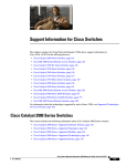
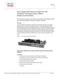
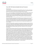
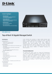
CH A P T E R
11
Cisco ASR 1001 Router Overview and Installation
This chapter describes the Cisco ASR 1001 Router and provides procedures for installing the
Cisco ASR 1001 Router on an equipment shelf or tabletop or in an equipment rack.
This chapter contains the following sections:
•
Cisco ASR 1001 Router Description, page 11-317
•
Installation Methods, page 11-332
•
General Rack Installation Guidelines, page 11-333
•
Guidelines for an Equipment Shelf or Tabletop Installation, page 11-334
•
Mounting the Cisco ASR 1001 Router on an Equipment Shelf or Tabletop Installation, page 11-334
•
Rack-Mounting the Cisco ASR 1001 Router, page 11-336
•
Attaching the Chassis Rack-Mount Brackets, page 11-337
•
Installing the Cisco ASR 1001 Router in a Rack, page 11-338
•
Attaching the Cable-Management Bracket, page 11-342
•
Attaching a Chassis Ground Connection, page 11-343
•
Connecting the Shared Port Adapter Cables, page 11-346
•
Connecting the Console and Auxiliary Port Cables, page 11-346
•
Connecting a Terminal to the Cisco ASR1000-RP1 Console Port, page 11-347
•
Connecting Cables, page 11-347
•
Auxiliary Connection, page 11-348
•
Overview of AC and DC Power Supplies for the Cisco ASR 1001 Router, page 11-348
•
Cisco ASR 1001 Router Power Supply Installation, page 11-348
Cisco ASR 1001 Router Description
The Cisco ASR 1001 Router is part of the Cisco aggregation services family of routers. The Cisco
ASR 1001 Router offers a compact form factor router that satisfies customer demands such as low power
consumption and decreased usage of rack space. The Cisco ASR 1001 Router has the route processor,
embedded services processor, and SIP integrated within the chassis with one half-height SPA slot.
By default, the Cisco ASR 1001 Router is shipped with 4 GB of DRAM. To implement software
redundancy, a minimum of 8 GB memory must be installed on the router.
Cisco ASR 1000 Series Aggregation Services Routers Hardware Installation Guide
OL-13208-11
11-317
Chapter 11
Cisco ASR 1001 Router Overview and Installation
Cisco ASR 1001 Router Description
The Cisco ASR 1001 Router supports:
•
ESP bandwidth 2.5 Gbps (default) to 5 Gbps of forwarding performance (optional software option)
•
ESP memory: 1-GB DRAM default; 1-GB DRAM maximum
•
Route-processor memory comes with 4-GB DRAM (default); 8-GB DRAM maximum
•
4-Gigabit Ethernet small form-factor pluggable (SFP) ports
For information about the SFP transceiver modules that are compatible with Cisco ASR 1002
Built-in Gigabit Ethernet Ports (4x1GE), refer to the “Modular Optics Compatibility” section in
Cisco ASR 1000 Series Aggregation Services Routers SIP and SPA Hardware Installation Guide.
•
External USB flash memory 1-GB USB flash memory support
Cisco ASR 1001 Router Architecture
The Cisco ASR 1001 Router provides all the Cisco ASR 1000 Series Router features, services, and
performance in a small form-factor chassis. The chassis contains a single integrated mainboard that
implements all functions of the route processor (RP), a SPA embedded processor (SIP), a forwarding
processor (ESP) and a built-in 4x1 GE SPA.
The SPA interface is connected to a built-in 4xGE SPA, a single half-height (HH) SPA bay, and one
flexible integrated daughter card (IDC), providing additional SPA interfaces.
Cisco ASR 1001 Router hardware features include:
•
Front-to-back air flow, with 7 built-in cooling fans, numbered from left to right, zero (0) to 6.
•
Supports 1 + 1 redundant AC or DC power supplies.
•
A cover interlock prevents cover removal with power supplies installed.
•
Provides one half-height SPA bay (Bay 1 online insertion and removal (OIR) supported) and
integrates a passive board, which consists of a standard SPA interface connector and an interface
connector, to the mainboard.
•
Support for one factory-configurable integrated daughter card in SPA Bay 2. The integrated
daughter card, in SPA Bay 2 is part of the base configuration, and is not an option.
•
Provides unique front panels for each integrated daughter card configuration.
•
8 GB internal flash
•
Console and Auxiliary RJ-45 ports
•
4 GB DRAM (default)
•
Forwarding Performance = 2.5G default, 5G with software license
The Cisco ASR 1001 Router can accommodate different integrated daughter cards. The chassis top cover
includes the integrated daughter card front panel with a common base chassis.There will be different top
covers for each integrated daughter cards and one for orders with no integrated daughter card.
The Cisco ASR 10001 Router can be shipped with different orderable configurations. The following IDC
configurations are available:
Note
See Appendix D, “MIBs for the Cisco ASR 1001 Router” for information about the MIBs that can be
used to manage these IDCs.
•
IDC-HD80G
Cisco ASR 1000 Series Aggregation Services Routers Hardware Installation Guide
11-318
OL-13208-11
Chapter 11
Cisco ASR 1001 Router Overview and Installation
Cisco ASR 1001 Router Description
IDC-HD80G can support a single 2.5-inch SATA HDD/SSD (see Figure 11-1).
Figure 11-1
Cisco ASR 1001 Router with IDC-HD80G
1
2
3
IDC-HD80G
HDD ONLINE
ACTIVITY
ASR 1001
CRIT
MAJ
USB LINK
MIN
BF
STAT
MGMT
12
AUX
8
10
11
CON
279784
PWR
9
7
5
6
7
4
1
HDD Online—LED indicates that the disk is
ready and can be accessed
2
HDD Activity—LED indicates that the disk is 8
currently being accessed
3
HDD Slot—Slot into which the HDD is
inserted (the figure shows an HDD inserted
into the slot)
9
4
AUX—RS-232 auxiliary port with modem
control signals
10 USB port—USB high-speed (480 Mbps) port
used for secure key storage, VPN credentials
storage, or bulk flash storage of image and
configuration backup
LINK LED—Indicates MGMT Ethernet port
activity
BF—Internal bootflash LED that indicates
activity of the EUSB device
USB LED
This USB port is an A port.
5
CON—RS-232 console port
11 STAT—Status LED
6
MGMT—RJ-45 10/100/1000 management
Ethernet port
12 PWR—Power LED
Cisco ASR 1000 Series Aggregation Services Routers Hardware Installation Guide
OL-13208-11
11-319
Chapter 11
Cisco ASR 1001 Router Overview and Installation
Cisco ASR 1001 Router Description
•
IDC-OC3POS
IDC-OC3POS can support two channels of OC3 (see Figure 11-2).
Figure 11-2
Cisco ASR 1001 Router with IDC-OC3POS
0
4
3
A/L
C/A
1
IDC-OC3POS
A/L
0
C/A
2
1
1
ASR 1001
CRIT
MAJ
USB LINK
MIN
BF
STAT
MGMT
13
AUX
9
11
12
CON
279783
PWR
10
8
6
7
5
1
C/A—Carrier/Alarm LED
8
LINK LED—Indicates MGMT Ethernet port
activity
2
A/L—Active/Loopback LED
9
BF—Internal bootflash LED that indicates
activity of the EUSB device
3
POS OC3—Port 0
10 USB LED
This POS port is a small form-factor
pluggable (SFP) port.
4
POS OC3—Port 1
This POS port is an SFP port.
11 USB port—USB high-speed (480 Mbps) port
used for secure key storage, VPN credentials
storage, or bulk flash storage of image and
configuration backup
This USB port is an A port.
5
AUX—RS-232 auxiliary port with modem
control signals
12 STAT—Status LED
6
CON—RS-232 console port
13 PWR—Power LED
7
MGMT—RJ-45 10/100/1000 management
Ethernet port
— —
Cisco ASR 1000 Series Aggregation Services Routers Hardware Installation Guide
11-320
OL-13208-11
Chapter 11
Cisco ASR 1001 Router Overview and Installation
Cisco ASR 1001 Router Description
•
IDC-4XGE
IDC-4XGE can support up to four small form-factor pluggable (SFP) transceivers, each of which
supports a 1-Gigabit Ethernet connection (see Figure 11-3).
Cisco ASR 1001 Router with IDC-4XGE
1
2
LINK
0
IDC-4XGE
LINK
3
LINK
1
LINK
4
3
2
Figure 11-3
ASR 1001
CRIT
MAJ
USB LINK
MIN
BF
STAT
MGMT
13
1
10
8
6
7
GigabitEthernet—Port 0
GigabitEthernet—Port 1
This POS port is an SFP port.
3
GigabitEthernet—Port 2
5
8
LINK LED—Indicates MGMT Ethernet port
activity
9
BF—Internal bootflash LED that indicates
activity of the EUSB device
This POS port is an SFP port.
2
AUX
9
11
12
CON
279782
PWR
10 USB LED
This POS port is an SFP port.
4
GigabitEthernet—Port 3
This POS port is an SFP port.
11 USB port—USB high-speed (480 Mbps) port
used for secure key storage, VPN credentials
storage, or bulk flash storage of image and
configuration backup
This USB port is an A port.
5
AUX—RS-232 auxiliary port with modem
control signals
12 STAT—Status LED
6
CON—RS-232 console port
13 PWR—Power LED
7
MGMT—RJ-45 10/100/1000 management
Ethernet port
— —
Cisco ASR 1000 Series Aggregation Services Routers Hardware Installation Guide
OL-13208-11
11-321
Chapter 11
Cisco ASR 1001 Router Overview and Installation
Cisco ASR 1001 Router Description
•
IDC-CHT1/E1
IDC-CHT1/E1 can support eight ports of fully channelized T1 or E1 interfaces (see Figure 11-4).
Cisco ASR 1001 Router with IDC-CHT1/E1
A/L C/A
1
3
C/A
4
MAJ
USB LINK
MIN
BF
MGMT
11
5
A/L C/A
6
A/L C/A
7
A/L
IDC-CHT1/E1
CON
AUX
7
9
10
8
6
4
5
T1/E1 Ports—Ports 0 through 3
T1/E1 Ports—Ports 4 through 7
3
7
BF—Internal bootflash LED that indicates
activity of the EUSB device
8
USB LED
9
USB port—USB high-speed (480 Mbps) port
used for secure key storage, VPN credentials
storage, or bulk flash storage of image and
configuration backup
These T1/E1 ports are RJ-45 ports.
2
A/L C/A
CRIT
STAT
1
A/L
5
2
4
A/L C/A
279786
PWR
1
3
A/L C/A
0
ASR 1001
0
2
C/A
2
7
1
6
Figure 11-4
These T1/E1 ports are RJ-45 ports.
3
AUX—RS-232 auxiliary port with modem
control signals
This USB port is an A port.
4
CON—RS-232 console port
10 STAT—Status LED
5
MGMT—RJ-45 10/100/1000 management
Ethernet port
11 PWR—Power LED
6
LINK LED—Indicates MGMT Ethernet port
activity
— —
Cisco ASR 1000 Series Aggregation Services Routers Hardware Installation Guide
11-322
OL-13208-11
Chapter 11
Cisco ASR 1001 Router Overview and Installation
Cisco ASR 1001 Router Description
•
IDC-4XT3
IDC-4XT3 can support up to four unchannelized DS3 (44.736 Mbps) ports (see Figure 11-5).
Cisco ASR 1001 Router with IDC-4XT3
4
A/L
C/A
1
C/A
A/L
TX
PWR
A/L
C/A
RX
TX
3
IDC-4XT3
A/L
RX
TX
RX
TX
RX
CRIT
MAJ
USB LINK
MIN
BF
STAT
MGMT
13
AUX
9
11
12
CON
279785
ASR 1001
2
3
0
3
0
C/A
2
1
1
2
Figure 11-5
10
8
6
7
5
1
C/A—Carrier/Alarm LED
8
LINK LED—Indicates MGMT Ethernet port
activity
2
A/L—Active/Loopback LED
9
BF—Internal bootflash LED that indicates
activity of the EUSB device
3
T3 TX Port—Transmit port 0
10 USB LED
This T3 port uses a 1.0/2.3 RF connector with
75-ohm impedance.
4
11 USB port—USB high-speed (480 Mbps) port
used for secure key storage, VPN credentials
This T3 port uses a 1.0/2.3 RF connector with
storage, or bulk flash storage of image and
75-ohm impedance.
configuration backup
T3 RX Port—Receive port 0
This USB port is an A port.
5
AUX—RS-232 auxiliary port with modem
control signals
12 STAT—Status LED
6
CON—RS-232 console port
13 PWR—Power LED
7
MGMT—RJ-45 10/100/1000 management
Ethernet port
— —
Cisco ASR 1000 Series Aggregation Services Routers Hardware Installation Guide
OL-13208-11
11-323
Chapter 11
Cisco ASR 1001 Router Overview and Installation
Cisco ASR 1001 Router Description
The following figures show the front panel of the Cisco ASR 1001 Router with the various IDCs.
Figure 11-6 shows the LEDs that are common to all configurations of the Cisco ASR 1001 Router.
Figure 11-6
Common LEDs for Cisco ASR 1001 Route Processor
1
2
3
4
ASR 1001
CRIT
PWR
MAJ
USB LINK
MIN
BF
9
8
279787
STAT
7
6
5
1
MAJ LED—major alarm indicator
6
BF—Internal bootflash LED indicates
activity of the EUSB device
2
CRIT LED—critical alarm indicator
7
MIN LED —minor alarm indicator
3
USB port— one USB high-speed (480Mbps)
port used for secure key storage, storing of
VPN credentials, or bulk flash storage for
image and configuration backup
8
STAT—status LED
4
USB LED
9
PWR—Power LED
5
LINK LED indicates MGMT Ethernet port
activity
— —
Note
For detailed descriptions of the SPAs on which some of the IDCs are based, go to:
http://www.cisco.com/en/US/products/ps6267/products_data_sheets_list.html
Note
There are two field-replaceable units in the Cisco ASR 1001 chassis. They are the DIMMs and eUSB.
In order to service the components in the chassis, you must remove the power supplies and the chassis
cover. For instructions, see the “Removing and Replacing the Cisco ASR 1001 Router DIMM Memory
Modules” section on page 14-28 and the “Remove and Replace the eUSB Device on the Cisco ASR 1001
Router” section on page 14-42.
Cisco ASR 1000 Series Aggregation Services Routers Hardware Installation Guide
11-324
OL-13208-11
Chapter 11
Cisco ASR 1001 Router Overview and Installation
Cisco ASR 1001 Router Description
Cisco ASR 1001 Router Faceplate Common Components
The Cisco ASR 1001 Router RP faceplate has common components for each type of ASR 1001 Router
configuration. Figure 11-6 and Figure 11-7 show the Cisco ASR1000-RP faceplate with LEDs and
connectors for all configurations of the Cisco ASR 1001 Router.
Figure 11-7
Common Connectors for Cisco ASR 1001 Route Processor
1
2
3
MGMT
CON
AUX
1
MGMT—One RJ-45 10/100/1000
management Ethernet port
3
2
CON—One RS-232 console port
— —
279883
LINK
AUX—One RS-232 auxiliary port with
modem control signals
Cisco ASR 1000 Series Aggregation Services Routers Hardware Installation Guide
OL-13208-11
11-325
Chapter 11
Cisco ASR 1001 Router Overview and Installation
Cisco ASR 1001 Router Description
Cisco ASR 1001 Chassis Front View
Figure 11-8 shows the front of the Cisco ASR 1001 Router.
Figure 11-8
Cisco ASR 1001 Router Front View
1
3
4
5
6
7
279915
2
13
12
11
9
10
8
1
PWR—Power LED
8
AUX—one RS-232 auxiliary port with
modem control signals
2
Integrated daughter card I/O space
9
CON—one RS-232 console port
3
GE 2/0 and 0/0—The built-in GE ports use
industry standard front-panel removable SFP
optics and SFP copper interfaces.
10 MGMT —one RJ-45 10/100/1000
management Ethernet port
4
GE 2/1 and 0/1
11 USB port
5
GE 2/2 and 0/2
12 CRIT LED—critical alarm indicator
MAJ LED—major alarm indicator
MIN LED —minor alarm indicator
6
GE 2/3 and 0/3
13 STAT—status LED
7
One half-height SPA Bay 1
— Bottom slot of chassis is Bay 0
Cisco ASR 1001 Chassis Rear View
Figure 11-9 shows the rear of the Cisco ASR 1001 Router with seven fans and two AC or DC power
supplies.
Figure 11-9
Cisco ASR 1001 Router Rear View
1
207700
0
Cisco ASR 1000 Series Aggregation Services Routers Hardware Installation Guide
11-326
OL-13208-11
Chapter 11
Cisco ASR 1001 Router Overview and Installation
Cisco ASR 1001 Router Description
Seven internal fans draw cooling air into the chassis and across internal components to maintain an
acceptable operating temperature. The fans are located at the rear of the chassis. A two-hole grounding
lug is located on the side of the chassis. Each individual fan also has a fan fail status signal. The fan fail
signal is asserted if the fan speed falls below 50% of the rated speed. The fans are numbered from zero
(0) to 6, left to right.
Two power supplies, either two AC power supplies or two DC power supplies are accessed from the rear
of the router.
Cisco ASR 1001 Router Slot Numbering
The SPA bay numbering scheme for Cisco ASR 1001 Router is different from the Cisco ASR 1000 SIP
card. The SPA ordering is: Built-in GE ports (SPA 0), SPA Bay 1 (SPA 1), and I/O Board (SPA 2).
The integrated daughter card is not necessarily a SPA; it could be any I/O, such as a harddrive or USB.
When the daughter card is not a SPA, then SPA Bay 2 will be left blank and not present in the system.
The built-in GE ports are logically SPA bay 0 and will be addressed as GE 0/0/x. The half-height SPA
slot is logically SPA bay 1 and ports will be addressed as 0/1/x. Ports on the integrated daughter card are
logically in SPA bay 2 and will be addressed as 0/2/x.
Figure 11-10 shows slot numbering for the Cisco ASR 1001 Router.
Figure 11-10
Cisco ASR 1001 Router Slot Numbering
1
2
ASR1001
Daughter Board I/O Space
STAT
0
0
CRIT
STAT
MAJ
PWR
MIN
MGMT
CONS
AUX
2/1
0/1
GE0
GE0
2/2
0/2
1
1
SPA 2xOC12
2/3
0/3
281352
0 USB 1
2/0
0/0
STAT
3
1
Slot 2 connected to the flexible integrated
daughter card
3
2
Slot 1 connected to the half-height SPA slot
— —
Slot 0 connected to the built-in 4x1GE SPA on
the mainboard
Cisco ASR 1001 Router Components
The Cisco ASR 1001 Router system is derived from the architecture of the other Cisco ASR 1000 Series
routers. The Cisco ASR 1001 Router contains a single mainboard that provides all the functions of a
Cisco ASR1000-RP (route proce4ssor), a Cisco ASR1000-SIP (carrier card), and a Cisco ASR1000-ESP
(forwarding processor). This mainboard assembly also contains a built-in 4x1 GE SPA providing four
SFP ports. The Cisco ASR1000-RP section of the mainboard provides all the traditional management
interfaces (Ethernet, Console, Aux) and a storage interface (USB only). The Cisco ASR1000-SIP section
provides one half-height SPA bay and a supports a flexible integrated daughter card. The Cisco
ASR1000-ESP section provides a CPP based forwarding engine including a security coprocessor.
Cisco ASR 1000 Series Aggregation Services Routers Hardware Installation Guide
OL-13208-11
11-327
Chapter 11
Cisco ASR 1001 Router Overview and Installation
Cisco ASR 1001 Router Description
The main components of the Cisco ASR 1001 Router, ASR1000-RP1, ASR1000-ESP5, and
ASR1000-SIP10 are fixed in the chassis and are not upgradeable, except for the power supplies and
SPAs.
Cisco Embedded ASR1000-RP1 for Cisco ASR 1001 Router Description
The Cisco ASR 1000 Series route processor (embedded for the Cisco ASR 1001 Router) is the central
control processor and runs the network operating system.
The Cisco embedded ASR1000-RP1 supports management interfaces such as the Ethernet network
management port and console and auxiliary serial ports. It has LED status indicators and one USB port
that can be used with smart cards for either secure key distribution or image or configuration file updates.
The Cisco embedded ASR1000-RP1 deviates from the other ASR Series Route Processor 1 for the Cisco
ASR 1006 router and the Cisco ASR 1004 Router in the following ways:
•
Bulk file storage is on a large eUSB device (to 8 GB supported) with no SATA hard-drive supported.
•
Redundant Cisco route processor is not supported.
•
Network clock changes. No second BITS clock input supported.
•
A built-in 4xGE SPA is included. This shared port adapter provides four SFP-based GE connections.
The Cisco route processor common LEDs and indicators are shown in Figure 11-6. Table 11-1 describes
the Cisco ASR 1000 Series Route Processor LEDs.
Table 11-1
Cisco ASR 1001 Series Route Processor LEDs
LED Label
LED
Color—State
Behavior Description
PWR
Power
Solid green
All power requirements are within specification
Off
Off. The router is in standby mode.
Solid green
Cisco IOSD and other required processes have loaded
successfully and are operating.
Yellow
ROMMON is running (including a permanent failure of RP
software) or the Process Manager has declared a critical RP
process (including IOSD) dead. A user can log in to recover.
Red
Occurs during system failure or power-up.
STAT
System status
CRIT
Critical
Solid Red
Functions as a critical alarm indicator. The LED is lso a solid
red during the boot process.
MAJ
Major
Solid Red
Major alarm indicator.
MIN
Minor
Amber
Minor alarm indicator.
BOOT
Internal eUSB
bootflash LED
Green
Activity indicator.
LINK
10/100/1000
Interface LED
Solid green
Link with no activity.
Flashing Green
MGMT Ethernet port activity.
Off
No link.
Cisco ASR 1000 Series Aggregation Services Routers Hardware Installation Guide
11-328
OL-13208-11
Chapter 11
Cisco ASR 1001 Router Overview and Installation
Cisco ASR 1001 Router Description
Cisco Embedded ASR1000-SIP10 and SPAs for the Cisco ASR 1001 Router Description
The Cisco embedded ASR1000-SIP10 is built into the Cisco ASR 1001 Router. The Cisco embedded
ASR1000-SIP10 provides the physical and electrical termination for up to three SPAs, built-in 4xGE
SPA, one half-height SPA bay, and one integrated daughter card (system configurable).
The Cisco embedded ASR1000-SIP10 interface, like the Cisco ASR 1006 Router and Cisco ASR 1004
Router, supports all Cisco embedded ASR1000-SIP10 functions and services. However, the Cisco
embedded ASR1000-SIP10 differs in the following areas:
•
Functions as the base board for Cisco embedded ASR1000-RP1
•
Is not a field-replaceable unit (FRU) and does not support online insertion and removal (OIR).
Note
Only the shared port adapter (SPA) on the Cisco embedded ASR1000-SIP10 in SPA Bay 1
of the Cisco ASR 1001 Router supports OIR.
The Cisco ASR 1001 Router embedded ASR1000-RP1 also provides the circuitry for the built-in 4xGE
SPA. Table 11-2 describes the built-in SPA LEDs.
Table 11-2
Built-In SPA LEDs
Function
Color
Description
GE SFP STATUS
(one per port)
Amber
Indicates that the port is enabled by software, but there is a
problem with the Ethernet link.
Green
Indicates that the port is enabled by software and there is a
valid Ethernet link.
Cisco ASR 1001 Router Integrated Daughter Card Description
The ASR 1001 Router supports different flexible integrated daughter cards with their own LEDs. Four
of these integrated daughter cards are based on SPAs and use the same external I/O ports as those SPAs.
One of the integrated daughter cards supports a single hard-disk-drive for other applications.
Table 11-3 describes the built-in SPA LEDs.
Table 11-3
Built-In SPA LEDs
Function
Color
Daughter Card Port Amber
Status (one per port)
Green
Description
Amber indicates the port is enabled by software, but there
is a problem with a port connection.
Green indicates the port is enabled by software and
operational.
Cisco ASR1000-ESP for the Cisco ASR 1001 Router Description
The Cisco ASR 1001 Router supports the Cisco ASR1000-ESP2.5 and Cisco ASR1000-ESP5 (with
license) embedded services processors.
Table 11-4 describes the Cisco ASR 1001 LEDs.
Cisco ASR 1000 Series Aggregation Services Routers Hardware Installation Guide
OL-13208-11
11-329
Chapter 11
Cisco ASR 1001 Router Overview and Installation
Cisco ASR 1001 Router Description
Table 11-4
Cisco ASR 1001 LEDs
No.
LED Label
LED
Color
Behavior Description
1
PWR
Power
Solid green
All power supplies are within operational limits.
Off
Off. The router is in standby mode.
2
ACTV
Active
Green
The embedded services processor is green when
active.
3
STAT
STATUS
Green
Code has downloaded successfully and is
operational.
Yellow
BOOT ROM has loaded successfully.
Red
Not booted.
None
Will always be off.
4
STBY
Standby
You can upgrade the throughput of the ESP from 2.5 Gbps to 5 Gbps by applying a software-activated
performance upgrade license and then reloading the router. If you want to determine the current
throughput level of the ESP, run the show platform hardware throughput level command. The
following example shows the output of this command before the performance upgrade license is applied:
Router# show platform hardware throughput level
The current throughput level is 2500000 kb/s
The following example shows the output of this command after the performance upgrade license is
applied:
Router# show platform hardware throughput level
The current throughput level is 5000000 kb/s
For more information about the software-activated performance upgrade license, see the Cisco ASR 1000
Series Aggregation Services Routers Release Notes at the following location:
http://www.cisco.com/en/US/docs/routers/asr1000/release/notes/asr1k_rn_rel_notes.html
Power Supplies in the Cisco ASR 1001 Router
The Cisco ASR 1001 Router power supply module supports the following Cisco power supplies:
•
AC power supply operates between 85 to 264 VAC
•
–48 VDC power supply input range supported is -40.5 to -72 VDC.
The power supply generates +12 V and +5 V, which is distributed to the mainboard and fans. The +5 V
is used to operate the power control devices. It also provides an operational +5 V, as needed.
The power supply units contain one or two fans that are only used for cooling the power supply. Each
power supply is self contained and controls its own fan speed and fan redundancy.
The power supplies are hot pluggable from the rear of the chassis and can be removed or installed while
the system is operating, without affecting any aspect of system performance. The Cisco ASR 1001
Router supports up to seven chassis-mounted cooling fans. Each fan provides an alarm output for error
indication speed measurement. The fans are not field replaceable, but the system can meet the cooling
requirements in the event of a single-fan failure.
Cisco ASR 1000 Series Aggregation Services Routers Hardware Installation Guide
11-330
OL-13208-11
Chapter 11
Cisco ASR 1001 Router Overview and Installation
Cisco ASR 1001 Router Description
AC Power Supply for Cisco ASR 1001 Router
The AC power supply input inlet is an IEC connector. The current rating on the connector is 10 A. The
AC power supply is secured into the chassis with two captive screws mounted on the faceplate.
Figure 11-11 shows the AC power supply for the Cisco ASR 1001 Router.
Figure 11-11
AC Power Supply for the Cisco ASR 1001 Router
207700
0
1
–48 VDC Power Supply for Cisco ASR 1001 Router
The –48 VDC power supply input connector accepts a Euro-style terminal block. It is compliant with
safety agencies’ guidelines and electrical requirements of the supply. The DC power supply operates
within specification from –40.5 to –72 VDC continuously once the power supply DC input reaches the
threshold of –43.5 V.
The –48 VDC power input connector Euro-style terminal block will accept three wires: one positive
polarity, one negative polarity, and one ground wire. The connection order is negative (–), positive (+),
and GND. The DC power supply is secured into the system chassis with two captive screws mounted on
the faceplate.
Figure 11-12 shows the –48 VDC power supplies for the Cisco ASR 1001 Router.
Figure 11-12
–48 VDC Power Supply for the Cisco ASR 1001 Router
207702
0
1
1
2
The output voltage alarm is declared when the output voltage is below the low end of the minimum or
above the high end of the maximum limits. When the output voltage is above the high end of the
minimum or below the low end of the maximum limits, the red state will not be activated.
Table 11-5 shows the –48 VDC power supply output voltage alarm ranges.
Cisco ASR 1000 Series Aggregation Services Routers Hardware Installation Guide
OL-13208-11
11-331
Chapter 11
Cisco ASR 1001 Router Overview and Installation
Installation Methods
Table 11-5
–48 VDC Power Supply Output Voltage Alarm Threshold Ranges
Output
Minimum
Maximum
12V
10.0-11.2V
12.8-13.8V
3.3V
2.6 - 3.0 V
None
Power Cords Supported by the Cisco ASR 1001 Router
Table 11-6 lists the power cords that are supported by the Cisco ASR 1001 Router.
Table 11-6
Power Cords Supported by the Cisco ASR 1001 Router
Power Cord Item Number
Description
15454-M-ACCBL-R2
AC Power Cable ANSI 220VAC Right Exit
CAB-AC-RA
Power Cord, 110 V, Right Angle
CAB-ACA-RA
Plug, Power Cord, Australian, 10 A, Right Angle
CAB-ACC-RA
Power Cord China, Right Angle
CAB-ACE-RA
Power Cord Europe, Right Angle
CAB-ACI-RA
Power Cord, Italian, Right Angle
CAB-ACR-RA
Power Cord Argentina, Right Angle
CAB-ACS-RA
Power Cord, Switzerland, Right Angle
CAB-ACU-RA
Power Cord UK, Right Angle
CAB-IND-RA
Power Cord India, Right Angle
CAB-JPN-RA
Power Cord-Japan, Right Angle
Installation Methods
Cisco ASR 1001 Router is designed for standalone, two rail 19-inch rack-mount (front rail only), four
rail 19-inch rack-mount (front and rear rail).
Although rack-mounting is the preferred method of installation for the Cisco ASR 1001 Router, you can
mount the chassis on an equipment shelf or tabletop.
Warning
This warning symbol means danger. You are in a situation that could cause bodily injury. Before you
work on any equipment, be aware of the hazards involved with electrical circuitry and be familiar
with standard practices for preventing accidents. Use the statement number provided at the end of
each warning to locate its translation in the translated safety warnings that accompanied this device.
Statement 1071
Warning
Before you install, operate, or service the system, read the Regulatory Compliance and Safety
Information for Cisco ASR 1000 Series Aggregation Services Routers publication. This document
provides important safety information you should know before working with the system. Statement 200
Cisco ASR 1000 Series Aggregation Services Routers Hardware Installation Guide
11-332
OL-13208-11
Chapter 11
Cisco ASR 1001 Router Overview and Installation
General Rack Installation Guidelines
Note
You have already unpacked your chassis and read all the site requirements for your new equipment.
Proceed with the installation.
General Rack Installation Guidelines
When planning your rack installation, consider the following guidelines:
Caution
•
The Cisco ASR 1001 Router requires a minimum of 3.5 inches or 8.9 cm rack units of vertical rack
space. Measure the proposed rack location before mounting the chassis in the rack.
•
Before using a particular rack, check for obstructions (such as a power strip) that could impair
rack-mount installation. If a power strip does impair a rack-mount installation, remove the power
strip before installing the chassis, and then replace it after the chassis is installed.
•
Allow sufficient clearance around the rack for maintenance. If the rack is mobile, you can push it
back near a wall or cabinet for normal operation and pull it out for maintenance (installing or moving
cards, connecting cables, or replacing or upgrading components). Otherwise, allow 19 inches (48.3
cm) of clearance to remove field-replaceable units.
•
Maintain a minimum clearance of 3 inches on the front and back sides of the chassis for the cooling
air inlet and exhaust ports, respectively. Avoid placing the chassis in an overly congested rack or
directly next to another equipment rack; otherwise, the heated exhaust air from other equipment can
enter the inlet air vents and cause an overtemperature condition inside the router.
To prevent chassis overheating, never install a Cisco ASR 1001 Router in an enclosed room that is not
properly ventilated or air conditioned.
•
Always install heavier equipment in the lower half of a rack to maintain a low center of gravity to
prevent the rack from falling over.
•
Install and use the cable-management brackets included with the Cisco ASR 1001 Router to keep
cables organized and out of the way of the cards and processors. Ensure that cables from other
equipment already installed in the rack do not impair access to the cards or require you to disconnect
cables unnecessarily to perform equipment maintenance or upgrades.
•
Install rack stabilizers (if available) before you mount the chassis.
•
Provide an adequate chassis ground (earth) connection for your router chassis.
In addition to the preceding guidelines, review the precautions for avoiding excessive temperature
conditions in the “Site Environmental Requirements” section on page 5-9.
Table 11-7 provides the Cisco ASR 1001 Router dimensions and weight information.
Table 11-7
Cisco ASR 1001 Router Dimensions and Weight
Cisco ASR 1001 Dimensions
Depth
22.50 in. (57.15 cm)
(including card handles, cable-management brackets, power
supply handles).
Height
1.71 in. (43.43 mm) - 1RU rack-mount
Cisco ASR 1000 Series Aggregation Services Routers Hardware Installation Guide
OL-13208-11
11-333
Chapter 11
Cisco ASR 1001 Router Overview and Installation
Guidelines for an Equipment Shelf or Tabletop Installation
Table 11-7
Cisco ASR 1001 Router Dimensions and Weight
Cisco ASR 1001 Dimensions
Width
17.25 in. (43.815 cm) - 19 inch rack-mount
Weight
40 lb (18.143 k) - fully configured
Guidelines for an Equipment Shelf or Tabletop Installation
The chassis should already be in the area where you will install it. If you have not determined where to
install your chassis, see the “Cisco ASR 1000 Series Routers Component Overview” section on page 2-1
for information about site considerations.
If you are not rack-mounting your Cisco ASR 1000 series chassis, place it on a sturdy equipment shelf
or tabletop.
When installing the Cisco ASR 1001 Router on an equipment shelf or tabletop, ensure that the surface
is clean and that you have considered the following:
•
The Cisco ASR 1001 Router requires at least 3 inches (7.62 cm) of clearance at the inlet and exhaust
vents (the front and top/rear sides of the chassis).
•
The Cisco ASR 1001 Router should be installed off the floor. Dust that accumulates on the floor is
drawn into the interior of the router by the cooling fans. Excessive dust inside the router can cause
overtemperature conditions and component failures.
•
There must be approximately 19 inches (48.3 cm) of clearance at the front and rear of the chassis to
install and replace FRUs, or to access network cables and equipment.
•
The Cisco ASR 1001 Router needs adequate ventilation. Do not install it in an enclosed cabinet
where ventilation is inadequate.
•
Keep the cable-management bracket ready if you plan to install it on the front of the chassis.
•
An adequate chassis ground (earth) connection exists for your router chassis (see the “Attaching a
Chassis Ground Connection” section on page 11-343).
•
Always follow proper lifting practices as outlined in the “Electrical Safety” section on page 5-21,
when handling the chassis.
Mounting the Cisco ASR 1001 Router on an Equipment Shelf or
Tabletop Installation
To mount your Cisco ASR 1001 Router on an equipment shelf or tabletop, follow these steps.
Step 1
Remove any debris and dust from the tabletop or platform, as well as the surrounding area.
Step 2
Lift the chassis into position on the equipment shelf or tabletop.
Warning
At least two people are required to lift the chassis onto a tabletop or platform. To prevent injury, keep
your back straight and lift with your legs, not your back. Statement 164
Cisco ASR 1000 Series Aggregation Services Routers Hardware Installation Guide
11-334
OL-13208-11
Chapter 11
Cisco ASR 1001 Router Overview and Installation
Mounting the Cisco ASR 1001 Router on an Equipment Shelf or Tabletop Installation
Step 3
Attach the front rack-mount brackets. Locate the threaded holes in the front sides of the chassis (first
holes beyond the vent holes) and use the package of black screws that shipped with the chassis.
Step 4
Align the front rack-mount bracket to one side of the chassis.
Step 5
Insert and tighten the screws on one side.
Step 6
Repeat Step 2 through Step 3 on the other side of the chassis. Use all screws to secure the rack-mount
brackets to the chassis.
Note
Step 7
The chassis rack-mount brackets must be installed first so that you can attach the
cable-management brackets to the chassis rack-mount brackets after the chassis is installed in
the rack.
Gather the two cable-management brackets and screws shipped with your chassis. Figure 11-13 shows
cable-management brackets attached on the front of the Cisco ASR 1001 Router.
Note
Make certain that the cable-management ‘U’ feature device has the open end pointing upwards
when you attach it to the chassis.
Attaching the Cable-Management Brackets to the Cisco ASR 1001 Router
279910
Figure 11-13
1
1
1
Cable-management bracket top and bottom
screws
3
Chassis front rack-mount bracket
2
Cable-management bracket
—
—
Step 8
Screw the cable-management bracket to each side of the rack-mount brackets that are attached to the
chassis. Use two screws for each cable-management bracket. Use a screw from the package of four
screws.
Step 9
Check that all screws are securely tightened.
Step 10
Go to the “Attaching a Chassis Ground Connection” section on page 11-343 for instructions about
continuing the installation.
Cisco ASR 1000 Series Aggregation Services Routers Hardware Installation Guide
OL-13208-11
11-335
Chapter 11
Cisco ASR 1001 Router Overview and Installation
Rack-Mounting the Cisco ASR 1001 Router
Rack-Mounting the Cisco ASR 1001 Router
The Cisco ASR 1001 Router can be installed in an existing rack with equipment or in an empty rack with
no equipment: The chassis can be mounted in either rack types:
•
Two-post rack, either 19 inch or 23 inch. Inner clearance (the width between the inner sides of the
two posts or rails) must be at least 19 inches (48.26 cm). The height of the chassis is 3.47 inches
(8.8 cm). Airflow through the chassis is from front to back.
Note
•
Note
If you are using a two-post rack secure the rack to the floor surface to prevent tipping and
avoid bodily.
Four post, 19-inch equipment rack. Inner clearance (the width between the inner sides of the two
posts or rails) must be at least 19 inches (48.26 cm). The height of the chassis is 1.71 inches (43.43
mm). Airflow through the chassis is from front to back.
When handling the chassis, always follow proper lifting practices. See the “Chassis-Lifting Guidelines”
section on page 5-23.
The Cisco ASR 1001 Router can be installed with both front or rear rack-mount brackets.
Verifying Rack Dimensions
Before you install the chassis, measure the space between the vertical mounting flanges (rails) on your
equipment rack to verify that the rack conforms to the measurements shown in Figure 11-14.
Figure 11-14
Verifying Equipment Rack Dimensions
Mounting flanges
Hole centerline
to hole centerline
18.31 inches ± 0.06 inches
(46.5 cm ± 0.15 cm)
Step 1
28014
Minimum usable
aperture 17.7 inches
(45.0 cm)
Mark and measure the distance between two holes on the left and right mounting rails.
The distance should measure 18.31 inches ± 0.06 inches (46.5 cm ± 0.15 cm).
Note
Measure for pairs of holes near the bottom, middle and top of the equipment rack to ensure that
the rack posts are parallel.
Cisco ASR 1000 Series Aggregation Services Routers Hardware Installation Guide
11-336
OL-13208-11
Chapter 11
Cisco ASR 1001 Router Overview and Installation
Attaching the Chassis Rack-Mount Brackets
Step 2
Measure the space between the inner edges of the left front and right front mounting flanges on the
equipment rack.
The space must be at least 17.7 inches (45 cm) to accommodate the chassis which is
17.25 inches (43.8 cm) wide and fits between the mounting posts on the rack.
Attaching the Chassis Rack-Mount Brackets
This section explains how to attach the front rack-mount brackets to the chassis. Before installing the
chassis in the rack, you must install the rack-mount brackets on each side of the chassis.
The parts and tools required for installing the rack-mount brackets and cable-management brackets are
listed in the “Tools and Equipment” section on page 5-23.
Note
The Cisco ASR 1001 Router also has a set of threaded features in the rear of the chassis to accommodate
a set of rear mounting brackets, should the requirement arise.
Note
The cable-management brackets are attached to the chassis after you install the chassis rack-mount
brackets on the chassis and mount the chassis in the rack.
Chassis Front Rack-Mount Brackets
Determine where in the rack you want the chassis to be mounted. If you are mounting more than one
chassis in the rack, then start from the bottom up or the center of the rack. Figure 11-15 shows the
brackets attached to the chassis. Depending on the bracket holes you use, the chassis may protrude in the
rack.
To install the front rack-mount brackets on the Cisco ASR 1001 Router, perform the following steps:
Step 1
Locate the threaded holes on the side of the chassis. Make certain that you hold the front rack-mount
bracket with the ear and holes facing outward and towards the front of the chassis.
Cisco ASR 1000 Series Aggregation Services Routers Hardware Installation Guide
OL-13208-11
11-337
Chapter 11
Cisco ASR 1001 Router Overview and Installation
Installing the Cisco ASR 1001 Router in a Rack
Figure 11-15 shows where to attach the front rack-mount brackets to the Cisco ASR 1001 Router.
Figure 11-15
Attaching the Front Rack-Mount Brackets to the Cisco ASR 1001 Router
279911
1
3
2
1
Front rack-mount bracket ear and holes
3
2
Front rack-mount bracket
— —
Front rack-mount bracket screws
Step 2
Position the front rack-mount bracket top hole with the chassis first top hole behind the side vent holes.
Step 3
Insert and tighten the black screws on one side.
Step 4
Repeat Step 1 through Step 3 on the other side of the chassis. Use black screws to secure the rack-mount
brackets to the chassis.
This completes the steps for attaching the front rack-mount brackets to the Cisco ASR 1001 Router.
Installing the Cisco ASR 1001 Router in a Rack
After installing the rack-mount brackets on the chassis, you mount the chassis by securing the
rack-mount brackets to two posts or mounting strips in the rack using the screws provided. Because the
rack-mount brackets support the weight of the entire chassis, be sure to use all screws to fasten the two
rack-mount brackets to the rack posts.
Warning
To prevent bodily injury when mounting or servicing this unit in a rack, you must take special
precautions to ensure that the system remains stable. The following guidelines are provided to ensure
your safety:
-This unit should be mounted at the bottom of the rack if it is the only unit in the rack.
-When mounting this unit in a partially filled rack, load the rack from the bottom to the top with the
heaviest component at the bottom of the rack.
-If the rack is provided with stabilizing devices, install the stabilizers before mounting or servicing
the unit in the rack. Statement 1006
We recommend that you allow at least 1 or 2 inches (2.54 or 5.08 cm) of vertical clearance between the
router and any equipment directly above and below it.
To install the chassis in the rack, perform the following steps:
Step 1
On the chassis, ensure that all screw fasteners on the installed components are securely tightened.
Cisco ASR 1000 Series Aggregation Services Routers Hardware Installation Guide
11-338
OL-13208-11
Chapter 11
Cisco ASR 1001 Router Overview and Installation
Installing the Cisco ASR 1001 Router in a Rack
Step 2
Make sure that your path to the rack is unobstructed. If the rack is on wheels, ensure that the brakes are
engaged or that the rack is otherwise stabilized. See the next sections on the types of racks you can use
to install the chassis.
Step 3
(Optional) Install a shelf in the rack to support the Cisco ASR 1001 Router. If you use a shelf, this will
help support the chassis while you secure it to the rack.
Step 4
With two people, lift the chassis into position between the rack posts.
Step 5
Align the mounting bracket holes with the rack post holes and attach the chassis to the rack.
Note
Step 6
Position the chassis until the rack-mounting flanges are flush against the mounting rails on the rack.
Tip
Step 7
Tip
Step 8
To allow space to attach the cable-management brackets to the chassis in the rack easily, use the
rack-mount bracket ear holes mentioned in Steps 7 and 8.
Hold the chassis in position against the mounting rails in the equipment rack and follow these steps:
a.
Tip
If you are using a shelf then raise the chassis to the level of the shelf. Let the bottom of the
chassis rest on the brackets, but continue to support the chassis.
Insert the bottom screw into the second hole up from the bottom of the rack-mount ear and use a
hand-held screwdriver to tighten the screw to the rack rail.
To make installation easier, insert one screw at the bottom of the chassis and the next screw at
the top of the chassis diagonally from the first screw.
b.
Insert the top screw into the second hole from the top of the rack-mount ear diagonally from the
bottom screw and tighten the screw to the rack rail.
c.
Insert the four screws to secure the chassis to the rack equipment.
By using the specified rack-mount bracket ear holes, the cable-management bracket can be easily
attached to the rack-mount bracket when the chassis is in the rack.
Tighten all screws on each side to secure the chassis to the equipment rack.
Cisco ASR 1000 Series Aggregation Services Routers Hardware Installation Guide
OL-13208-11
11-339
Chapter 11
Cisco ASR 1001 Router Overview and Installation
Installing the Cisco ASR 1001 Router in a Rack
Two-Post Rack Installation
The Cisco ASR 1001 Router can be installed on a two-post rack, either 19 inch or 23 inch.
Note
Caution
Step 1
Inner clearance (the width between the inner sides of the two posts or rails) must be at least 19 inches
(48.26 cm). The height of the chassis is 1.71 inches (43.43 mm). Airflow through the chassis is from
front to back.
If you are using a two-post rack secure the rack to the floor surface to prevent tipping and avoid bodily
injury and component damage.
Position the chassis so the front is closest to you and lift it carefully into the rack. To prevent injury,
avoid any sudden twists or moves.
Figure 11-16 shows the Cisco ASR 1001 Router on a two-post equipment rack.
Cisco ASR 1001 Router Installed on a Two-Post Equipment Rack
279912
Figure 11-16
Step 2
Slide the chassis into the rack, pushing it back until the brackets meet the mounting strips or posts on
both sides of the rack.
Step 3
Keeping the brackets flush against the posts or mounting strips, align the holes in the brackets with the
holes on the rack or mounting strip.
Step 4
For each bracket, insert and tighten two screws to the rack on both sides.
This completes the procedure for installing the chassis on a two-post rack. Proceed to the “Attaching a
Chassis Ground Connection” section on page 11-343 to continue the installation.
Cisco ASR 1000 Series Aggregation Services Routers Hardware Installation Guide
11-340
OL-13208-11
Chapter 11
Cisco ASR 1001 Router Overview and Installation
Installing the Cisco ASR 1001 Router in a Rack
Four-Post Rack Installation
The Cisco ASR 1001 Router can be flush-mounted in a 19-inch equipment rack using the rack-mounting
kit provided with your system. The Cisco ASR 1001 Router can be mounted into the rack using two
recommended methods:
•
Installing the chassis in an existing rack with equipment.
•
Installing an empty chassis in a rack with no equipment installed.
When handling the chassis, always follow proper lifting practices. See the “Chassis-Lifting Guidelines”
section on page 5-23.
Note
Inner clearance (the width between the inner sides of the two posts or rails) must be at least 19 inches
(48.26 cm). The height of the chassis 1.71 inches (43.43 mm). Airflow through the chassis is from front
to back.
Note
Make sure the rack is stabilized.
Step 1
(Optional) Install a shelf in the rack to support the Cisco ASR 1001 Router. If you are using a shelf then
raise the chassis to the level of the shelf. Let the bottom of the chassis rest on the brackets, but continue
to support the chassis. Using two people, lift the chassis into the rack using the side handles and grasping
underneath the power supply bays.
Step 2
Position the chassis until the rack-mounting flanges are flush against the mounting rails on the rack.
Note
Use the second hole up from the bottom of the rack-mount bracket and the second hole down from the
top of the rack-mount bracket. This will make it easier to attach the cable-management bracket to the
chassis in the equipment rack.
Step 3
Hold the chassis in position against the mounting rails while the second person finger-tightens a screw
to the rack rails on each side of the chassis.
Step 4
Finger-tighten screws to the rack rails on each side of the chassis.
Step 5
Tighten all screws on each side to secure the chassis to the equipment rack.
Cisco ASR 1000 Series Aggregation Services Routers Hardware Installation Guide
OL-13208-11
11-341
Chapter 11
Cisco ASR 1001 Router Overview and Installation
Attaching the Cable-Management Bracket
Figure 11-17 shows front and rear rack-mounting of the Cisco ASR 1001 Router on a four-post rack.
Cisco ASR 1001 Router in a Four Post Rack—Front and Rear Rack-Mounting
279913
Figure 11-17
Step 6
Use a level to verify that the tops of the two brackets are level, or use a measuring tape to verify that both
brackets are the same distance from the top of the rack rails.
This completes the procedure for installing the chassis in the rack. Proceed to the “Attaching the
Cable-Management Bracket” section on page 11-342 to continue the installation.
Attaching the Cable-Management Bracket
The cable-management brackets mount to each rack-mount bracket on the chassis to provide
cable-management to both sides of the chassis (parallel with card orientation). These brackets are screw
mounted to the rack-mount brackets to allow easy installation and removal of cables.
The cable-management brackets for the Cisco ASR 1001 Router contain one independent
cable-management “U” type features with four screws and provides cable dressing of each card module
slot.
Note
Make certain that the cable-management bracket “U” type feature is facing upwards when you attach it
to the chassis.
Follow these steps to attach the cable-management brackets to both sides of the Cisco ASR 1001 Router
in the rack:
Cisco ASR 1000 Series Aggregation Services Routers Hardware Installation Guide
11-342
OL-13208-11
Chapter 11
Cisco ASR 1001 Router Overview and Installation
Attaching a Chassis Ground Connection
Step 1
Align the cable-management bracket to the rack-mount bracket on one side of the Cisco ASR 1001
Router. The cable-management bracket aligns to the top hole of the chassis rack-mount bracket.
Step 2
Using a Phillips screwdriver, insert the screw through cable-management bracket and into the chassis
rack-mount and tighten the screw.
Note
Use the package of screws that came with your chassis containing four screws.
Figure 11-18 shows where to attach the front rack-mount brackets to the Cisco ASR 1001 Router in a
rack.
Chassis Rack-Mount Bracket Ear Holes for the Cable-Management Bracket
279910
Figure 11-18
1
1
1
Step 3
Secure the cable-management screw to the middle ear hole of the front rack-mount bracket on
both sides of the Cisco ASR 1001 Router.
Using the bottom rack-mount ear hole, insert the screw through cable-management bracket and into the
chassis rack-mount (see Figure 11-18).
This completes the procedure for installing the cable-management brackets on the chassis.
Attaching a Chassis Ground Connection
Connecting the Cisco ASR 1000 Series Router to ground is required for all DC powered installations
and any AC powered installation where compliance with Telcordia grounding requirements is necessary.
Caution
The dual-lug chassis stud must be installed, the SIP and SPA must be fully inserted and screwed in and
earthed to prevent a potential hazard in a telecom line.
Have the recommended tools and supplies available before you begin this procedure.
Cisco ASR 1000 Series Aggregation Services Routers Hardware Installation Guide
OL-13208-11
11-343
Chapter 11
Cisco ASR 1001 Router Overview and Installation
Attaching a Chassis Ground Connection
Recommended Tools and Supplies
The following tools, equipment, and supplies necessary to connect the system ground to the chassis:
•
Phillips screwdriver
•
3.5 mm flat blade screwdriver (Phoenix # 1205053 or equivalent 3.5 mm flat blade)
•
Dual-lug chassis ground component
•
Grounding wire
Figure 11-19 shows how to attach the ground lugs on the Cisco ASR 1000 Series chassis. The location
of the ground lug on Cisco ASR 1000 Series Routers may not be the same on all routers; but the ground
lug attachment instructions are similar.
Installing a Ground Connection on the Cisco ASR 1001 Router
207763
Figure 11-19
4
3
2
Warning
2
1
1
Chassis ground studs and lead wire
3
Ground connector on the chassis
2
Grounding screws
4
Ground symbol
This equipment must be grounded. Never defeat the ground conductor or operate the equipment in the
absence of a suitably installed ground conductor. Contact the appropriate electrical inspection
authority or an electrician if you are uncertain that suitable grounding is available. Statement 1024
Before you connect power or turn on power to your chassis, you must provide an adequate chassis ground
(earth) connection for the chassis. A chassis ground connector is provided on each Cisco ASR 1001
Router. There is a stud on the side of the chassis and on the DC power supply (primary grounding stud).
Cisco ASR 1000 Series Aggregation Services Routers Hardware Installation Guide
11-344
OL-13208-11
Chapter 11
Cisco ASR 1001 Router Overview and Installation
Attaching a Chassis Ground Connection
Caution
The grounding wire is always the first to be installed or connected and the last to be removed or
disconnected.
Use the following procedure to attach the grounding lug to the chassis ground connector on your chassis:
Step 1
Use the wire stripper to strip one end of the AWG #6 wire approximately 0.75 inches (19.05 mm).
Step 2
Insert the AWG #6 wire into the wire receptacle on the grounding lug.
Step 3
Use the crimping tool to carefully crimp the wire receptacle around the wire; this step is required to
ensure a proper mechanical connection as shown in the next figure.
Step 4
Attach the grounding lug with the wire so that the grounding wire does not overlap the power supply.
Figure 11-20 shows how to attach a grounding lug to the chassis ground connector.
Figure 11-20
Attaching a Grounding Lug to the Chassis Ground Connector
3
2
280186
1
4
1
Chassis ground lead wire
3
Ground screws
2
Grounding stud
4
Chassis ground connector holes
Step 5
Locate the chassis ground connector on the side of your chassis.
Step 6
Insert the two screws through the holes in the grounding lug.
Step 7
Use the Number 2 Phillips screwdriver to carefully tighten the screws until the grounding lug is held
firmly to the chassis. Do not overtighten the screws.
Step 8
Connect the opposite end of the grounding wire to the appropriate grounding point at your site to ensure
an adequate chassis ground.
This completes the procedure for attaching a chassis ground connection.
Cisco ASR 1000 Series Aggregation Services Routers Hardware Installation Guide
OL-13208-11
11-345
Chapter 11
Cisco ASR 1001 Router Overview and Installation
Connecting the Shared Port Adapter Cables
Connecting the Shared Port Adapter Cables
The instructions for connecting the cables for the shared port adapter installed in the Cisco ASR 1001
Router are contained in the respective configuration documents for each port adapter. For example, if
you are connecting the optical fiber cables for the PA-POS-OC3 port adapter, see PA-POS-OC3 Port
Adapter Installation and Configuration at the following location:
http://www.cisco.com/en/US/partner/docs/interfaces_modules/port_adapters/install_upgrade/pos/pa-po
s-oc3_install_config/paposoc3.html
Connecting the Console and Auxiliary Port Cables
This section describes how to attach a cable to the Cisco embedded ASR1000-RP1 console or auxiliary
ports on the Cisco ASR 1001 Router. The Cisco ASR 1001 Router uses RJ-45 ports for both the auxiliary
port and console port to attach a modem or console terminal.
Caution
Both the console and the auxiliary ports are asynchronous serial ports; any devices connected to these
ports must be capable of asynchronous transmission. (Asynchronous is the most common type of serial
device; for example, most modems are asynchronous devices.) To meet Class A emissions requirements,
shielded cables must be used for the console and auxiliary port connectors.
Before you can use the console interface on the router using a terminal or PC, you must perform the
following steps:
Step 1
Before connecting a terminal to the console port, configure the terminal to match the chassis console
port as follows: 9600 baud, 8 data bits, no parity, 1 stop bits (9600 8N1).
Step 2
Connect to the port using the RJ-45 to DB-9 cable.
Note
Step 3
For information about how to change the default settings to meet the requirements of your terminal or
host, see Cisco IOS Terminal Services Configuration Guide.
After you establish normal router operation, you can disconnect the terminal.
Management Ethernet Port Cable Connection
Caution
To comply with Class A emissions requirements, a shielded Ethernet cable must be used for the
connection.
To use the Management Ethernet interface on the router, perform the following steps:
Step 1
Insert an Ethernet RJ-45 cable into the MGMT ETHERNET port (see Figure 11-7).
Cisco ASR 1000 Series Aggregation Services Routers Hardware Installation Guide
11-346
OL-13208-11
Chapter 11
Cisco ASR 1001 Router Overview and Installation
Connecting a Terminal to the Cisco ASR1000-RP1 Console Port
Step 2
Insert the other end of the RJ-45 cable to your management device or network.
Connecting a Terminal to the Cisco ASR1000-RP1 Console Port
The Cisco ASR 1001 embedded route processor has an asynchronous serial (EIA/TIA-232) RJ-45
console port labeled CON on its front panel. You can connect this port to most types of video terminals
through use of the console cable kit that is included with your Cisco ASR 1001 Router. The console
cable kit contains:
•
One RJ-45 to RJ-45 crossover cable
•
One RJ-45 to DB-25 (female) adapter
•
One RJ-45 to DB-9 (female) adapter
A crossover cable reverses pin connections from one end to the other. In other words, it connects pin 1
(at one end) to pin 8 (at the other end), pin 2 to pin 7, pin 3 to pin 6, and so on. You can identify a
crossover cable by comparing the two modular ends of the cable. Hold the cable ends in your hand,
side-by-side, with the tabs at the back. Ensure that the wire connected to the outside (left) pin of the left
plug (pin 1) is the same color as the wire connected to the outside (right) pin of the right plug (pin 8).
Use the following procedure to connect a video terminal to the console port on a route processor.
Note
Each Cisco ASR 1000 Series Route Processor must have a console port connection (typically to a
terminal server) if you are running a redundant configuration in the chassis.
Step 1
Connect one end of the RJ-45 cables to the serial RJ-45 port (CON) on the Cisco embedded
ASR1000-RP1 (see Figure 11-7).
Step 2
Run the cable up and through the cable-management bracket and connect the other end of the RJ-45
cable to the RJ-45 adapter (see Figure 11-21).
Step 3
Connect the adapter to your video terminal to complete the cable connection.
Step 4
Power on your video terminal.
Step 5
Configure your video terminal to match the following default console port settings:
Step 6
•
9600 baud
•
8 data bits
•
No parity generation or checking
•
1 stop bit
•
No flow control
Go to the “Connecting Cables” section on page 11-347 to continue the installation.
Connecting Cables
Keep the following guidelines in mind when connecting external cables to the Cisco ASR 1001 Router:
•
To reduce the chance of interference, avoid crossing high-power lines with any interface cables.
Cisco ASR 1000 Series Aggregation Services Routers Hardware Installation Guide
OL-13208-11
11-347
Chapter 11
Cisco ASR 1001 Router Overview and Installation
Auxiliary Connection
•
Verify all cabling limitations (particularly distance) before powering on the system.
Auxiliary Connection
This asynchronous EIA/TIA-232 serial port (AUX) is used to connect a modem to the Cisco ASR 1000
Series Route Processor 1 for remote administrative access. Use the following procedure to connect the
Cisco ASR 1001 Router to a modem.
Step 1
Connect one end of the modem cable to the RJ-45 port on the primary Cisco ASR 1000 Series Route
Processor 1, labeled AUX. For the AUX port connection, see Figure 11-7.
Step 2
Run the cable up and through the cable-management bracket and connect the other end of the cable to
your modem.
Overview of AC and DC Power Supplies for the Cisco ASR 1001
Router
The Cisco ASR 1001 Router power supplies each provide 400 W of output power and are used in a 1 + 1
redundant configuration. There is no input switch on the faceplate of the power supplies. The power
supply will be switched from Standby to ON by way of a system chassis STANDBY/ON switch. The
power supply slot numbers are on the rear of the chassis to the left side of each power supply. When
facing the rear of the chassis, power supply slot 0 (PS0) is to the left and power supply slot 1(PS1) is to
the right (next to the power supply Standby switch).
The Cisco ASR 1001 Router supports the following power supplies:
•
Cisco ASR 1001 Router AC power supply—Provides 400 watt output power with two DC voltage
outputs: +12 V and +5 V. The AC power supply operates between 85 and 264 VAC. The AC power
supply current shares on the 12 V output and is used in a dual hot pluggable configuration. The AC
power supply consumes a maximum of 471 W of input power.
•
Cisco ASR 1001 Router DC power supply—Provides 400 watt output power with two DC voltage
outputs: +12 V and +5.0 V. The power supply operates between –40.5 and –72 VDC. The DC power
supply current shares on the 12 V output and is used in a dual hot pluggable configuration. The DC
power supply consumes a maximum of 500 W of input power.
Cisco ASR 1001 Router Power Supply Installation
The Cisco ASR 1001 Router AC and DC power supplies are shipped installed in the chassis. You must
connect the power supplies when they arrive.
Cisco ASR 1000 Series Aggregation Services Routers Hardware Installation Guide
11-348
OL-13208-11
Chapter 11
Cisco ASR 1001 Router Overview and Installation
Cisco ASR 1001 Router Power Supply Installation
Note
The Cisco ASR 1001 Router can support two AC or two DC power supplies. Do not mix AC and DC
power supply units in the same chassis.
Figure 11-21 shows both the AC and DC power supplies for the Cisco ASR 1001 Router.
Figure 11-21
1
2
Cisco ASR 1001 Router AC Power Supply and DC Power Supply
3
1
4
5
6
100-240
V~
5-2A
50-60Hz
14A
207693
-48V/-60V
8
1
8
7
3
1
1
AC and DC power supply fasteners
5
DC power supply positive (+) connection
2
AC power supply inlet
6
DC power supply ground symbol
3
Power supply LED
7
DC power supply terminal block connection
4
DC power supply negative (-) connection
8
AC and DC power supply handles
Table 11-8 describes the power supply LED. The function of the LED is the same for both the AC and
DC power supplies.
Table 11-8
Cisco ASR 1001 Router AC and DC Power Supply LED
LED Color and State
Description
Solid green
Power output is on and within the normal operating range.
Blinking green, at the rate of one
blink per second
Input power that is within the normal operating range is being
supplied, but the Standby switch is in the Standby position (and
not in the On position).
Solid amber
A power supply critical event has occurred, and the power
supply has shut down. The critical event can be temperature,
voltage, current, or fan operating outside the normal operating
range.
Blinking amber, at the rate of one
blink per second
A power supply warning event has occurred, but the power
supply can continue to operate. The warning event can be
temperature, voltage, current, or fan operating outside the
normal operating range.
Off
Power supply is shut down.
Cisco ASR 1000 Series Aggregation Services Routers Hardware Installation Guide
OL-13208-11
11-349
Chapter 11
Cisco ASR 1001 Router Overview and Installation
Cisco ASR 1001 Router Power Supply Installation
This section contains the following topics:
•
Installing AC Input Power to Cisco ASR 1001 Router, page 11-350
•
Removing AC Power Supply from the Cisco ASR 1001 Router, page 11-352
•
Installing DC Input Power on the Cisco ASR 1001 Router, page 11-354
•
Removing DC Input Power from the Cisco ASR 1001 Router, page 11-359
Warning
The covers are an integral part of the safety design of the product. Do not operate the unit without the
covers installed. Statement 1077
Warning
When you install the unit, the ground connection must always be made first and disconnected last.
Statement 1046
Warning
Before performing any of the following procedures, ensure that power is removed from the DC circuit.
Statement 1003
Warning
Only trained and qualified personnel should be allowed to install, replace, or service this equipment.
Statement 1030
Installing AC Input Power to Cisco ASR 1001 Router
The Cisco ASR 1001 Router has two AC power supplies in the rear of the chassis. The input receptacle
is an IEC60320 C14 type of filtered AC inlet. The current rating on the connector is 10 A.
Warning
Do not install the power supplies with the chassis cover off.
Figure 11-22 shows the Cisco ASR 1001 Router AC power supplies.
Figure 11-22
Cisco ASR 1001 Router AC Power Supplies
1
207700
0
Follow these steps to connect an AC input power supply to the Cisco ASR 1001 Router.
Step 1
There are two power supplies installed. At the rear of the chassis, check that the power switch on the
chassis is in the standby position.
Cisco ASR 1000 Series Aggregation Services Routers Hardware Installation Guide
11-350
OL-13208-11
Chapter 11
Cisco ASR 1001 Router Overview and Installation
Cisco ASR 1001 Router Power Supply Installation
Figure 11-23 shows the Cisco ASR 1001 Router AC power supply standby switch.
Cisco ASR 1001 Router AC Power Supply Standby Switch
207695
Figure 11-23
1
1
Cisco ASR 1001 Router Standby switch, which does not disconnect power from the power source.
Step 2
Turn off the circuit breaker to the power supply.
Step 3
For easier installation, plug the power cable into the inlet on power supply slot 1 first.
Step 4
Then insert the power supply cable into the power supply in slot 0 on the right.
Cisco ASR 1000 Series Aggregation Services Routers Hardware Installation Guide
OL-13208-11
11-351
Chapter 11
Cisco ASR 1001 Router Overview and Installation
Cisco ASR 1001 Router Power Supply Installation
Step 5
Make certain that the AC power cords are positioned as shown in Figure 11-24.
Correct Position of the Cisco ASR 1001 Router AC Power Supply Cables
207697
Figure 11-24
1
3
2
1
AC power supply in PS0
3
2
Position of power supply cable from PS0
— —
AC power supply in PS1
Step 6
Plug the AC power supply cables into the AC power source.
Step 7
Turn on the AC breaker.
Step 8
Turn the Standby switch to On (|) on the chassis.
Step 9
The power supply LED illuminates green.
This completes the procedure for connecting AC input power.
Removing AC Power Supply from the Cisco ASR 1001 Router
This section describes how to remove an AC power supply from the Cisco ASR 1001 Router. The Cisco
ASR 1001 Router has two power supply slots, power supply slot 1 (PS1) next to the Standby switch and
power supply slot 0 (PS0) to the left, as shown in Figure 11-22.
Follow these steps to remove an AC power supply from the Cisco ASR 1001 router:
Step 1
Unplug the power cable from the power source.
Cisco ASR 1000 Series Aggregation Services Routers Hardware Installation Guide
11-352
OL-13208-11
Chapter 11
Cisco ASR 1001 Router Overview and Installation
Cisco ASR 1001 Router Power Supply Installation
Step 2
To remove the power cord from PS1, position the power supply cable in order to access the power supply
fasteners. Hold back the power supply cable in PS0, as shown in Figure 11-25, ensuring that you do not
unplug the power cable.
Positioning the AC Power Supply Cable in Slot PS0
207698
Figure 11-25
Step 3
Tip
Step 4
Continue to hold back the power supply cable in PS0, to gain access to the fastener. Unscrew both
fasteners on the power supply in slot 1.
The Cisco ASR 1001 power supplies are long and narrow. It is recommended that when you pull the
power supply out of the chassis, you support the power supply from the bottom with the other hand.
After the power supply fasteners are loosened, grasp the handle with one hand, support the weight of the
power supply with the other hand, and pull the power supply out of the slot. Figure 11-26 shows how to
remove the Cisco ASR 1001 Router AC power supply cables.
Removing the Cisco ASR 1001 Router AC Power Supply Cables
207699
Figure 11-26
Step 5
Repeat these steps to remove the AC power supply from Slot PS0.
This completes the procedure of removing the AC power supply from the Cisco ASR 1001 Router.
Cisco ASR 1000 Series Aggregation Services Routers Hardware Installation Guide
OL-13208-11
11-353
Chapter 11
Cisco ASR 1001 Router Overview and Installation
Cisco ASR 1001 Router Power Supply Installation
Installing DC Input Power on the Cisco ASR 1001 Router
The Cisco ASR 1001 Router DC input connector is compatible with a pluggable Euro-style plug. The
input connector and plug must be UL recognized under UL 486 for field wiring. The connection polarity
shall be from left to right: negative (–), positive (+), and ground. See Figure 11-21.
The power supply has a handle, to assist in insertion and extraction. The module must be supported with
one hand because of its length. Figure 11-27 shows the rear view of the Cisco ASR 1001 Router DC
power supply.
Figure 11-27
Cisco ASR 1001 Router DC Power Supply Rear View
207702
0
1
1
1
DC power supply in slot 0
2
2
DC power supply in slot 1
This section describes how to install the DC power supply ground leads and input power leads to the
Cisco ASR 1001 Router DC input power supply. Before you begin, read these important notices:
Warning
•
The color coding of the DC input power supply leads depends on the color coding of the DC power
source at your site. Typically, green or green/yellow is used for ground (GND), black is used for –48
V on the negative (–) terminal, and red is used for RTN on the positive (+) terminal. Ensure that the
lead color coding you choose for the DC input power supply matches the lead color coding used at
the DC power source.
•
Ensure that the chassis ground is connected on the chassis before you begin installing the DC power
supply. Follow the steps provided in the “Attaching a Chassis Ground Connection” section on
page 11-343.
When you install a power supply unit, the ground connection should always be made first and
disconnected last. Statement 1046
To connect the DC power supply on the Cisco ASDR 1001 Router, follow these steps:
Step 1
Ensure that the chassis ground is connected on the chassis before you begin installing the DC power
supply, as described in the “Attaching a Chassis Ground Connection” section on page 11-343.
Step 2
At the rear of the chassis, next to the power supply bay PS1, ensure that the power supply switch is in
Standby position.
Cisco ASR 1000 Series Aggregation Services Routers Hardware Installation Guide
11-354
OL-13208-11
Chapter 11
Cisco ASR 1001 Router Overview and Installation
Cisco ASR 1001 Router Power Supply Installation
Step 3
Turn off the circuit breaker to the power supply.
Wiring the DC Input Power Source
The Cisco ASR 1001 Router DC power supply has a connector plug that is installed into the power
supply terminal block header. Figure 11-28 shows a view of a DC power supply with a DC connector
plug inserted (no wires installed) into the power supply block header in power supply PS0 (on the left),
and the other power supply with no connector plug inserted into power supply PS1 (on the right).
Cisco ASR 1001 Router DC Power Supply Terminal Block With a Connector Plug in
Slot 0 and Without a Connector Plug in Slot 1
207694
Figure 11-28
Note
Two types of DC connector plugs are supported for use with the DC power supply for the Cisco ASR
1001 Router. In one type of connector plug, the screw holes are raised above the connector plug body.
In the second type, the screw holes are not raised above the connector plug body. Figure 11-30 shows
the connector plug in which the screw holes are not raised. The only difference in the method for using
these two types of connector plugs is related to the wire-strip length, which is mentioned later in this
section.
Warning
When installing or replacing the unit, the ground connection must always be made first and
disconnected last. Statement 1046
Warning
This product relies on the building’s installation for short-circuit (overcurrent) protection. Ensure that
the protective device is rated not greater than: 120 VAC, 20A U.S. (240 VAC, 10A international).
Statement 1005
Warning
Before performing any of the following procedures, ensure that power is removed from the DC circuit.
Statement 1003
Warning
Only trained and qualified personnel should be allowed to install, replace, or service this equipment.
Statement 1030
Cisco ASR 1000 Series Aggregation Services Routers Hardware Installation Guide
OL-13208-11
11-355
Chapter 11
Cisco ASR 1001 Router Overview and Installation
Cisco ASR 1001 Router Power Supply Installation
Use the information provided in this section to wire the DC input power source:
Step 1
At the front of the router, ensure that the power switch is in the Standby position.
Step 2
Move the circuit-breaker switch handle to the Off position, and apply tape to hold it in the Off position.
Step 3
Gather the DC power supply terminal block plug.
Step 4
Insert the lead wires before inserting the plug into the terminal block header on the DC power supply.
Step 5
Use a 10 gauge wire-stripping tool to strip each of the three wires coming from the DC input power
source. If you are using the connector plug with the raised screw holes, strip the wires to 0.39 inch (10
mm) + 0.02 inch (0.5 mm). If you are using the connector plug with the screw holes that are not raised,
strip the wires to 0.27 inch (7 mm) + 0.02 inch (0.5 mm). Do not strip more than the recommended length
of wire because doing so could leave the wire exposed from the terminal block plug. Figure 11-29 shows
a stripped DC input power source wire.
Figure 11-29
Stripping the DC Input Power Source Wire
57019
1
1
Warning
Step 6
0.39 inch (10 mm) is the recommended wire-strip length for the connector plug that has raised
screw holes. 0.27 inch (7 mm) is the recommended wire-strip length for the connector plug that
does not have raised screw holes.
An exposed wire lead from a DC input power source can conduct harmful levels of electricity. Be sure
that no exposed portion of the DC input power source wire extends from the terminal block plug.
Statement 122
Identify the positive, negative, and ground feed positions for the terminal block connection. The
recommended wiring sequence is:
•
Ground lead wire (right)
•
Positive (+) lead wire (middle)
•
Negative (–) lead wire (left)
Cisco ASR 1000 Series Aggregation Services Routers Hardware Installation Guide
11-356
OL-13208-11
Chapter 11
Cisco ASR 1001 Router Overview and Installation
Cisco ASR 1001 Router Power Supply Installation
Figure 11-30 shows the DC power supply with lead wires.
Figure 11-30
DC Power Supply with Lead Wires
1
2
207765
3
1
Negative (–) lead wire
3
2
Positive (+) lead wire
— —
Ground lead wire
Step 7
Insert the exposed wire of one of the ground wire into the terminal block plug. Ensure that you cannot
see any wire lead. Only wires with insulation should extend from the terminal block.
Caution
Do not overtorque the terminal block plug captive screws. The recommended maximum torque is from
0.5 Nm (4.425 lbf in.) to 0.6 Nm (5.310 lbf in.).
Cisco ASR 1000 Series Aggregation Services Routers Hardware Installation Guide
OL-13208-11
11-357
Chapter 11
Cisco ASR 1001 Router Overview and Installation
Cisco ASR 1001 Router Power Supply Installation
Step 8
Use a ratcheting torque screwdriver to torque the terminal block plug captive screw (above the installed
wire lead) to from 0.5 Nm (4.425 lbf in. to 0.6 Nm (5.310 lbf in.), as shown in Figure 11-31.
Figure 11-31
Torquing the DC Power Supply Terminal Block Plug Screws
207764
1
1
Step 9
Torque is from 0.5 Nm (4.425 lbf in.) to 0.6 Nm (5.310 lbf in.)
Repeat Step 6 through Step 8 for the remaining two DC input power source wires, the positive lead wire
and the negative lead wire.
Figure 11-32 shows how to insert the DC power supply terminal block plug in the block header.
Figure 11-32
Inserting the DC Power Supply Terminal Block Plug in the Block Header
2
3
207696
1
1
DC power supply negative (-) lead wire
3
2
DC power supply positive (+) lead wire
— —
DC power supply ground lead wire
Cisco ASR 1000 Series Aggregation Services Routers Hardware Installation Guide
11-358
OL-13208-11
Chapter 11
Cisco ASR 1001 Router Overview and Installation
Cisco ASR 1001 Router Power Supply Installation
Caution
Step 10
Secure the wires coming in from the terminal block plug so that they cannot be disturbed by casual
contact.
Use a tie wrap to secure the wires to the rack, so that the wires are not pulled from the terminal block
plug by casual contact. Make sure the tie wrap allows for some slack in the ground wire. Figure 11-33
shows the DC terminal block plug inserted and the tie wrap secured.
Complete DC Terminal Block Plug Insertion and Secure Tie Wrap
207701
Figure 11-33
1
1
Lead wires secured with a tie wrap
2
2
DC power supply terminal block plug being
inserted into terminal block header.
Step 11
Ensure that the terminal block plug is fully seated in the terminal block header on the DC power supply
panel. You will hear a snap or click when installed properly.
Step 12
Remove the tape (if any) from the circuit breaker switch handle, and move the circuit breaker switch
handle to the On position.
Step 13
At the rear of the router, place the power supply Standby switch in the On position to turn on the router.
The power supply LEDs light up when power is supplied to the router.
This completes the procedure for connecting the DC power supply in the Cisco ASR 1001 Router.
Removing DC Input Power from the Cisco ASR 1001 Router
This section describes how to remove a DC power supply from the Cisco ASR 1001 Router. Follow these
steps:
Step 1
Turn off the circuit breaker.
Step 2
Pull the terminal block plug connector out of the terminal block head in the power supply.
Step 3
Unscrew the two power supply fasteners on the unit.
Cisco ASR 1000 Series Aggregation Services Routers Hardware Installation Guide
OL-13208-11
11-359
Chapter 11
Cisco ASR 1001 Router Overview and Installation
Cisco ASR 1001 Router Power Supply Installation
Step 4
Grasping the power supply handle with one hand, pull the power supply out of the chassis while
supporting it with the other hand.
This completes the procedure for removing the DC power supply from the Cisco ASR 1001 Router.
Cisco ASR 1000 Series Aggregation Services Routers Hardware Installation Guide
11-360
OL-13208-11