1
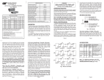
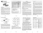
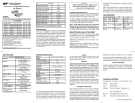
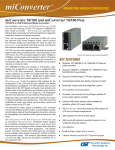
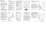
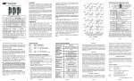
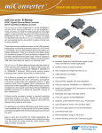
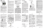
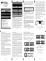
Accessories
™
miConverter 10/100 Plus
Rx
Tx
Lambda Lambda
[nm]
[nm]
ST
SC
MM / DF
5km
1120-0-x
1122-0-x
1310
1310
SM / DF
30km
1121-1-x
1123-1-x
1310
1310
SM / DF
60km
1121-2-x
1123-2-x
1310
1310
SM / DF
120km
-
1123-3-x
1550
1550
SM / SF
20km
-
1130-1-x
1310
1550
SM / SF
40km
-
1130-2-x
1310
1550
SM / SF
20km
-
1131-1-x
1550
1310
SM / SF
40km
-
1131-2-x
1550
1310
When choosing power options, replace (-x) in the model number
with the suffix number that corresponds to the power supply of
choice below. Example: 1103-3-6 stands for
1103-3-x with USB Power Adapter
-1
US Power Supply - 120Volt / 60Hz
-2
Universal Power Supply (requires AC power cord) 100-240Volt / 50-60Hz
-3
Euro Power Supply - 100-240Volt / 50-60Hz
-4
UK Power Supply - 100-240Volt / 50-60Hz
-5
Australia Power Supply - 100-240Volt / 50-60Hz
-6
USB Power Adapter Cable
-8
US/JPN Power Supply - 100-240Volt / 50-60Hz
For power supplies -3, -4, -5 and -8, country/region specific clips are
used to provide the necessary power connection.
Page 1
UTP Mode Selection
The UTP port is configured using the DIP-switches
as shown in Figure 1. There are four modes of
operation based on the position of the DIP-switches.
The factory default configuration is “AN” Autonegotiation. In the “AN” mode, the port will advertise
100Mbps Full-Duplex, 100Mbps Half-Duplex, 10Mbps
Full-Duplex and 10Mbps Half-Duplex.
The UTP port can be configured for Manual negotiation
by setting the appropriate DIP-switches. The port
can be configured for 100Mbps Full-Duplex, 100Mbps
Half-Duplex and 10Mbps Half-Duplex.
Link Mode Selection
The miConverter 10/100 Plus can be configured for
several different Link Modes. The DIP-switch
illustration in Figure 1 indicates how to configure the
different Link Modes.
Link Segment (LS)
“LS” (factory default) generates and detects a link
signal at each point in the network. Utilizing this
configuration, a loss of a receive link signal will only
affect the port detecting the loss of signal. All the
other ports will continue to generate a link signal.
Figure 2(A) indicates the normal operation of the
system without faults. Figure 2(B) indicates a loss
of a receive link on the fiber optic port, the UTP
port continues to maintain its link.
Page 5
USB Power Adapter Cable
9130-2
Universal AC Power Adapter
(requires AC power cord)
miConverter 10/100 Plus Models
Connector Types
4381
US Domestic AC Power Adapter
Media Converter
User Manual
Fiber Mode Type /
Dual Fiber [DF] or Distance
Single-Fiber [SF]
Wall Mounting Hardware Kit
9113-PS
available with the 10/100 Plus, including Link Segment
(Normal Mode), Link Propagate (Link Loss Carry
Forward), Remote Fault Detection and Symmetrical
Fault Detection. The link mode assist in the
identification and isolation of link failures.
9115-PS
Europe AC Power Adapter
9116-PS-3
United Kingdom AC Power Adapter
9116-PS-4
Australia AC Power Adapter
9116-PS-5
Japanese AC Power Adapter
9116-PS-8
European Connector Clip*
9116-3
UK Connector Clip*
9116-4
Australian Connector Clip*
9116-5
Japanese Connector Clip*
9116-8
*All spare Connector Clips are interchangeable with AC Power
Adapters 9116-PS-3, 9116-PS-4, 9116-PS-5 and 9116-PS-8
DESCRIPTION
The miConverter™ 10/100 Plus is a 10/100BASE-T copper
to 100BASE-FX fiber media converter. The UTP copper
port can automatically detect the speed, duplex mode
and crossover mode of the connected device, or it can
be manually configured via DIP-switches.
The 100BASE-FX fiber port operates in Full-Duplex
mode and supports single-mode or multimode fiber
with ST or SC fiber connectors. Single-mode models
feature Bi-Directional fiber and support distances of
up to 40km. The various fiber models options are
described in the table on the first page.
WARNING!
Before inserting the Power Adapter, verify
that the power on the unit is appropriate
for your AC line voltage source.
POWER ADAPTER NOTICE
This product should only be used with Omnitron supplied
Power Supply model numbers 9113-PS, 9115-PS,
9130-2, 9116-PS-3, 9116-PS-4, 9116-PS-5 or
9116-PS-8.
In order to guarantee performance when powering the
miConverter 10/100 Plus with the USB Power
Adapter cable (P/N 9130-2), the cable must be
connected to a Full-Powered USB Type-A port (5V,
500mA).
negotiation and the Link Mode is “LS” Link Segment.
2. Connect the UTP port to a 10BASE-T or 100BASE-TX
Ethernet device using a Category 5 cable (or better).
3. Connect the fiber optic port to a 100BASE-FX Fast
Ethernet device via the fiber cable of the appropriate
mode and type. When connecting dual fiber models,
the miConverter 10/100 Plus transmitter (Tx) must
attach to the receiver side of its link partner; the
receiver (Rx) must attach to the transmitter. When
connecting single-fiber (SF) models, the Tx
wavelength on one end has to match the Rx wavelength
on the other. Based on this guideline, the SF media
converter models must be used in pairs, such as the
1130-2-x matched with the 1131-2-x.
4. Mount the miConverter 10/100 Plus using the
included Velcro ® strips or optional wall-mounting
bracket kit (P/N 1091-0).
5. Connect the appropriate power source.
DIP-SWITCH SETTINGS
Link Mode
NOTE: Not all USB Type-A ports are Full-Powered
USB ports. The Full-Powered USB Type-A ports
are usually the USB ports found on computer
cases or on self-powered (powered by an AC
adapter) USB hubs.
UTP Mode
LS (default)
AN Auto (default)
LP
MAN 10Mbps HD
MAN 100Mbps HD
MAN 100Mbps FD
INSTALLATION PROCEDURE
1. Configure the miConverter 10/100 Plus with the
Several Link Modes (fault-detection capabilities) are
appropriate DIP-switch settings. The factory default
configuration for the UTP copper port is “AN” Auto-
Figure 1: DIP-switch Configurations
Page 2
Page 3
Page 4
Link Propagate (LP)
“LP” generates (transmits) a link signal only when a
link signal is detected. Utilizing this configuration, a
loss of a receive link signal will continue to ‘propagate’
through to the next port in the network. In Figure
2(C), a loss of a receive link on the fiber optic port
causes the UTP port to drop its link due to the
propagated fiber optic link state. This setting allows
the loss of a link to be detected by SNMP or other
managed network devices to which the miConverter
10/100 Plus is connected.
Symmetrical Fault Detect (SFD)
“SFD” generates a Link Loss signal on all ports on
both media converters when a loss of link signal is
detected by one of the ports. In Figure 2(E), the
pattern of LEDs gives an indication of the failure
point.
NOTE: Only the first loss of a receive link detected by
the miConverter 10/100 Plus turns off the other port’s
transmit link. An additional loss of a receive link on the
other port has no affect on the miConverter 10/100
Plus. The miConverter 10/100 Plus returns to normal
operation when the first loss of a receive link is restored.
Remote Fault Detect + Link Segment (RFD + LS)
“RFD+LS” generates a link signal only when a link
signal is detected. However, instead of propagating
the fault forward, the loss of link is looped back. In
Figure 2(D), a loss of a received link state is looped
back causing the port to stop transmitted the link
state. Because the other unit is configured for Link
Propagate, the UTP port will drop its link due to the
propagated fiber optic link state.
NOTE: It is not permitted to set both Converter A and
B to RFD at the same time; a deadly embrace will
occur.
Page 6
RFD+LS
LP
(D)
NOTE: Both media converters must be configured
with the SFD Link Mode. The SFD function is only
supported by Omnitron Systems equipment.
RFD
Switch 1
Converter A
Converter B
SFD
SFD
Switch 2
Normal Operation
(A)
Switch 1
(E)
Fiber
UTP
UTP
Fiber
UTP
Converter A
Converter B
LS
LS
Switch 2
Converter A
LP
Converter B
Switch 1
Converter A
LED ON
LED Flashing
(B)
Switch 1
RFD
UTP
Switch 2
LP
Converter A
Page 7
Converter B
Switch 2
LED OFF
LED ON or OFF
- LED status depends on the link
type; AN - OFF, MAN - ON
Figure 2: Link Modes
(C)
Switch 1
Converter B
Switch 2
Page 8
LED INDICATORS:
Function Legend Color
SPECIFICATIONS:
Off
Power
Pwr
Amber No power
Power applied
F/O LinkAct
F/O
Green No link
Solid = Link
Rapid Blinking (10Hz)
= Data
Slow Blinking (5Hz)
= SFD Error Det.
UTP LinkAct
UTP
Green No link
Solid = Link
Rapid Blinking (10Hz)
= Data
Slow Blinking (5Hz)
= SFD Error Det.
10(Off) /
100(On)
100
HDX(Off) /
FDX(On)
FDX
miConverter 10/100 Plus Specifications
On
Green UTP = 10Mbps UTP = 100Mbps when
when UTP Link UTP Link is active
is active
Green Half-Duplex
Full-Duplex when UTP
when UTP Link Link is active
is active
NOTE: For additional assistance with the LED
indicators, please refer to the miConverter 10/100
Plus TROUBLESHOOTING GUIDE (pp 12 -13).
Description
Protocols
Miniature 10/100BASE-T Copper
to 100BASE-FX Fiber
Media Converter
10BASE-T, 100BASE-TX,
100BASE-FX
with 1536 bytes max. frame size,
IEEE 802.3 specification
Cable Types
UTP
Fiber
EIA/TIA 568A/B,
Category 5 and higher
Multimode: 50/125, 62.5/125,
100/140 um
Single-mode: 9/125 um
Connector Types
RJ45
Dual fiber: SC, ST
Single-fiber: SC
Pwr, FO-Lk/Act, UTP-Lk/Act,
UTP-10/100, HDX/FDX
Power Requirements
DC Power
DC Power Connector
AC Power Adapter
[US]
AC Power Adapter
[Universal or
Country/Region Specific]
TROUBLESHOOTING GUIDE:
Dimensions
Problem:
The Power LED does not illuminate after installation
is complete.
W:1.71" x L:4.10" x H:0.84"
Weight
without power adapter
with USB power adapter cable
with AC power adapter [US]
with AC power adapter
[Universal]
Compliance
0.5A @ 5VDC
2.5mm DC Jack - Center Positive
100-120VAC/60Hz
0.03A @ 120VAC
4 oz.
5 oz.
12 oz.
Possible Causes:
A. Confirm that the power supply is connected.
18 oz.
B. Confirm that the correct power supply is being
used.
UL, CE, FCC Class A
Temperature
0 to +50oC
-50 to +80oC
Operational - Commercial
Storage
Humidity
(non-condensing)
5% to 95%
Altitude
UTP
Fiber
LED Displays
SPECIFICATIONS (CONT.):
-100m to 4000m
MTBF [hrs]
without power adapter
with US or
Country/Region Specific
power adapter
with Universal power adapter
1,000,000
250,000
100,000
Problem:
The Fiber Optic link LED does not illuminate after
installation is complete.
Possible Causes:
A. Confirm that the fiber optic cable is properly
connected to the miConverter 10/100 Plus and the
remote fiber optic device.
B. Confirm that the fiber cable type matches the
fiber transceiver type (multimode, single-mode) on
the miConverter 10/100 Plus.
C. If using a dual-fiber model, confirm that the
transmitter (Tx) is attached to the receiver side of its
link partner, and that the receiver (Rx) is attached to
the transmitter.
D. If using a single-fiber model, confirm that the Tx
wavelength on the miConverter 10/100 Plus matches
the Rx of the connected fiber optic device.
100-240VAC/50-60Hz
0.03A @ 120VAC
E. Verify the Link Mode selection is set to Link
Segment (LS). Until a stable link is established, leave
the Link Mode configured for LS. After a Link presence
Page 9
is established, the Link Mode selection can be
modified.
Problem:
The UTP link LED does not illuminate after installation
is complete.
Possible Causes:
A. Confirm that the UTP cable is connected properly
to the miConverter 10/100 Plus and the attached
UTP device.
B. Confirm that the UTP cable pin-out is correct (EIA/
TIA-568-A).
C. Verify the miConverter 10/100 Plus UTP port is
configured with the proper settings based on the
attached device (AN or MAN, 10 or 100, HD or FD).
NOTE: If corrective actions do not resolve your
situation, please contact Omnitron Systems
Technical Support.
Page 10
Page 11
Warning
Limitation of Warranty
The operating description in this Instruction Manual is
for use by qualified personnel only. To avoid electrical
shock, do not perform any servicing of this unit other
than that contained in the operating instructions, unless
you are qualified and certified to do so by Omnitron
Systems Technology, Inc.
The foregoing warranty shall not apply to defects
resulting from improper or inadequate use and/or
maintenance of the equipment by Buyer, Buyersupplied equipment, Buyer-supplied interfacing,
unauthorized modifications or tampering with
equipment (including removal of equipment cover by
personnel not specifically authorized and certified by
Omnitron), or misuse, or operating outside the
environmental specification of the product (including
but not limited to voltage, ambient temperature,
radiation, unusual dust, etc.), or improper site
preparation or maintenance.
Warranty
This product is warranted to the original purchaser
against defects in material and workmanship for a
period of TWO YEARS from the date of shipment. A
LIFETIME warranty may be obtained by the original
purchaser by REGISTERING this product with
Omnitron within 90 days from the date of shipment.
TO REGISTER, COMPLETE AND MAIL OR FAX THE
ENCLOSED REGISTRATION FORM TO THE
INDICATED ADDRESS. Or you may register your
product on the Internet at http://www.omnitronsystems.com. During the warranty period, Omnitron
will, at its option, repair or replace a product which is
proven to be defective.
For warranty service, the product must be sent to an
Omnitron designated facility, at Buyer’s expense.
Omnitron will pay the shipping charge to return the
product to Buyer’s designated US address using
Omnitron’s standard shipping method.
Page 12
TECHNICAL SUPPORT:
For help with this product, contact Omnitron’s Tech.
Support:
Phone:
(949) 250-6510
Fax:
(949) 250-6514
Address:
Omnitron Systems Technology, Inc.
140 Technology #500
Irvine, CA 92618 USA
E-mail:
[email protected]
URL:
http://www.omnitron-systems.com
No other warranty is expressed or implied. Omnitron
specifically disclaims the implied warranties of
merchantability and fitness for any particular purpose.
Exclusive Remedies
The remedies provided herein are the Buyer’s sole
and exclusive remedies. Omnitron shall not be liable
for any direct, indirect, special, incidental, or
consequential damages, whether based on contract,
tort, or any legal theory.
Form: 040-11200 -001 B 11/07
Page 13
Page 14
Page 15
Page 16